

Page 1
Installation Instructions
SED2 VFD LON Interface Option
WARNING:
Personal injury/loss of life may
procedure as specified.
CAUTION:
Equipment damage, or loss of
perform a procedure as specified.
WARNING:
remove the LON Interface Option.
SED2
LON
Product Description
The LONMARK® certified SED2 VFD LON Interface
Option (LON
SED2 Variable Frequency Drives (VFDs). The LON
Interface resides on a LONWORKS® network with
ONMARK products from multiple vendors.
L
Interface) provides direct digital control of
Document No. 129-387
October 2, 2009
6. Reinstall SED2 VFD op erat or panel on LON
Interface.
Product Numbers
SED2-LONI/F, includes SED2 VFD LON Interface
Option, and CD-ROM with files and oper ati ng
instructions.
Warning/Caution Notations
occur if you do not perform a
data may occur if you do not
Installation
SED2 VFD Frame Sizes A, B, and C
Make sure that the SED2 VFD is
de-energized (off) before you install or
1. Remove the SED2 VFD operator panel.
2. Install the LON
module (Figure 1) by inserting two bottom guides
into appropriate slots at the sides of the I/O
module and pushing the upper section inward
until the locking mechanism latches.
Interface on the SED2 VFD I/O
INTERFACE
OPTION
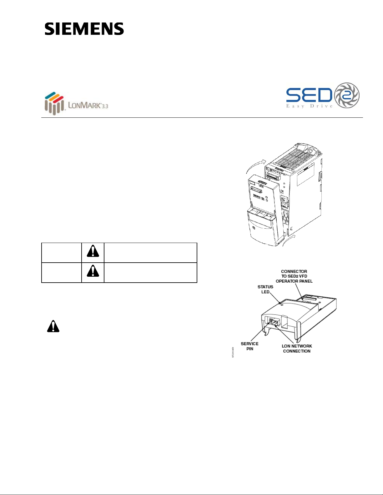
Figure 1. Installing LON Interface Option on SED2 VFD
Frame Sizes A, B, and C.
Figure 2. Network Connection on Bottom of
LON Interface Option.
VFD
3. Route the network cable (without connector) to
the LON
4. Terminate the end of network cable with a single,
two-pin, female L
5. Attach the network cable FTT-10A connector to
connector at bottom of LON
Item Number 129-387, Rev. BA Page 1 of 3
Interface.
ONWorks FTT-10A connector.
Interface (Figure 2).
Page 2

Document No. 129-387
WARNING:
remove the LON Interface Option.
Installation Instructions
October 2, 2009
SED2 VFD Frame Sizes D, E, and F
Make sure that the SED2 VFD is
de-energized (off) before you install or
For frame sizes D, E, and F, the LON Interface mounts
inside the VFD housing.
1. Remove the SED2 VFD operator panel, side
cover, and bottom cover (Figures 3).
2. Disconnect operator panel extension module
(with ribbon cable) from control module by
pushing lever above extension module upwards
and simultaneously pulling extension module from
the upper sides and rocking it downward.
NOTE: Do not disconnect the ribbon cable.
3. Install the LON
(Figure 4) by inserting two bottom guides into
appropriate slots at the sides of the control
module and pushing the upper section inward
until the locking mechanism latches.
4. Install the operator panel extension module on
Interface (Figure 4) by inserting two bottom
LON
guides into appropriate slots at the sides of the
Interface and pushing the upper section
LON
inward until the locking mechanism latches.
Interface on the control module
6. Terminate the end of network cable with a single,
two-pin, female L
ONWorks FTT-10A connector.
7. Attach the network cable FTT-10A connector to
connector at bottom of LON
Interface (Figure 2
and 4).
8. Reinstall the bottom cover, side cover, and the
SED2 VFD operator panel.
5. Route the network cable (without connector)
through a suitable cable opening to the LON
Interface (Figure 4).
Figure 3. Removing the Operator Panel and Side Cover
of SED2 VFD Frame Sizes D, E, F.
Figure 4. Installing LON Interface Option on SED2 VFD Frame Sizes D, E, and F.
Page 2 of 3 Siemens Industry, Inc.
Page 3
Document No. 129-387
Siemens Industry, Inc.
+ 1 847-215-1000
Your feedback is important to us. If you have
Document No. 129-387
WARNING:
should start the bus.
Installation Instructions
October 2, 2009
Wiring
A VFD can be switched on uni nten t iona lly if
the serial bus installation is not operated
correctly. Only personnel who are qualified
and trained in installing systems of this type
DIP Switch
Leave DIP switches OFF for proper operation of the
Interface.
LON
WIRING
Wiring must conform to local codes and ordinances.
WIRE ROUTING
Maintain a minimum of 5 ft (1.5 m) between VFDs and
network or sensor wiring.
If it is necessary for network and sensor wring to cross
VFD wiring, it should cross at 90-degree angles.
POWER
The LON
VFD connection. If VFD power is switched off, the
LON
Interface receives power through its SED2
Interface will not communicate on the network.
NOTE: This connection supports twisted pair,
unshielded, polarity-insensitive, peer-to-peer
communications at 78 Kbps.
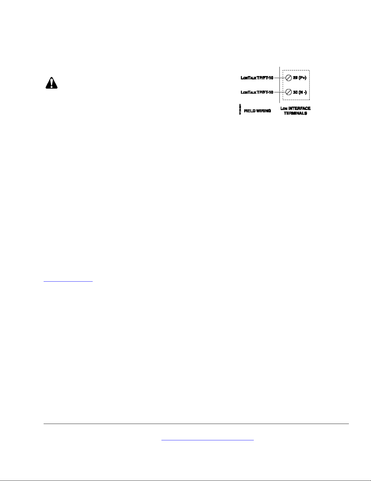
Figure 5. LON Interface Option Wiring Schematic.
LONTalk® NETWORK
ONTalk network connection is on the bottom
The L
edge of the LON
Interface (Figure 2). Figure 5 shows
the wiring schematic for this connection. See
www.echelon.com for more details on the network
cable and the FTT-10A connector.
The installation is now complete.
Information in this publication is based on current specifications. The company reserves the right to make changes in specifications and
models as design improvements are introduced. Echelon, LonMark, LonWorks, LonTalk are registered trademarks of Echelon Corporation.
Product or company names mentioned herein may be the trademarks of their respective owners. © 2009 Siemens Industry, Inc.
Building Technologies Division
1000 Deerfield Parkway
Buffalo Grove, IL 60089
comments about this document, please send them
to [email protected]
Printed in the USA
Page 3 of 3
 Loading...