

Siemens SED2-0.75/22B, SED2-0.55/22B, SED2-2.2/22B, SED2-3/22B, SED2-4/22B Operating Instructions Manual
...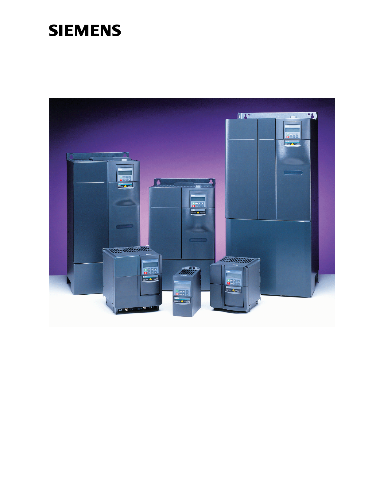
SED2 variable speed drives
Operating instructions
CM1U5192en
01.2002
Siemens Building Technologies
HVAC Products

2/126
Siemens Building Technologies SED2 variable speed drives CM1U5192en
HVAC Products 01.2002

3/126
Siemens Building Technologies SED2 variable speed drives CM1U5192en
HVAC Products Introduction 01.2002
Table of contents
1 Introduction ...................................................................................................7
1.1 Purpose of this document .............................................................................7
1.2 Validity...........................................................................................................7
1.3 Target audience............................................................................................7
1.4 Document structure.......................................................................................7
1.5 Referenced documents.................................................................................7
1.6 Document conventions..................................................................................8
1.7 Environmental compatibility and disposal.....................................................9
2 Safety instructions.......................................................................................11
2.1 General........................................................................................................11
2.2 Commissioning............................................................................................11
2.3 Operation.....................................................................................................12
2.4 Repairs........................................................................................................12
3 Mechanical installation................................................................................13
3.1 Installing the SED2 after extended storage.................................................13
3.2 Ambient conditions......................................................................................13
3.3 Mounting......................................................................................................14
3.3.1 Dimensions of SED2 drives with IP20/NEMA 0 rating ................................14
3.3.1.1 Dimensions of SED2 frame sizes A to C.....................................................14
3.3.1.2 Dimensions of SED2 footprint filters for frame sizes A to C........................15
3.3.1.3 Dimensions of SED2 frame sizes D to F.....................................................15
3.3.2 Dimensions of SED2 drives with IP54/NEMA 12 rating ..............................16
3.3.2.1 Dimensions of SED2 frame sizes B and C..................................................16
3.3.2.2 Dimensions of SED2 frame sizes D to F.....................................................16
3.3.3 Mounting SED2 drives with IP20/NEMA 0 rating ........................................17
3.3.4 Mounting SED2 drives with IP54 / NEMA 12 rating ....................................18
4 Electrical installation....................................................................................19
4.1 General........................................................................................................19
4.1.1 Maximum length of motor cables ................................................................19
4.1.2 Operation with ungrounded systems...........................................................19
4.1.2.1 Precautions for ungrounded systems (IT protective systems) .................... 19
4.1.3 Operation with a residual current device (RCD)..........................................22
4.2 EMC-compatible installation........................................................................23
4.2.1 EMC-compatible wiring ...............................................................................23
4.3 Mains and motor connections .....................................................................25
4.3.1 Access to connection terminals: Frame size A............................................26
4.3.2 Access to connection terminals: Frame sizes B and C...............................27
4.3.3 Access to connection terminals: Frame sizes D to F IP20..........................28
4.3.4 Power and motor terminals: Frame sizes A to F.........................................30

4/126
Siemens Building Technologies SED2 variable speed drives CM1U5192en
HVAC Products Introduction 01.2002
4.3.5 Power connection for drives with a built-in EMC filter ................................31
4.3.6 Tightening torque for connection terminals ................................................ 34
4.3.7 Cross-sections for power and motor cables ............................................... 34
4.3.8 Block diagram showing typical installation ................................................. 36
4.3.9 Direction of rotation .................................................................................... 36
4.3.10 Star or delta connection..............................................................................37
4.3.11 Connecting several motors......................................................................... 37
4.3.12 External motor overload protection.............................................................37
4.4 Control terminals ........................................................................................ 38
4.5 SED2 block diagram...................................................................................39
5 Commissioning........................................................................................... 41
5.1.1 DIP switch settings.....................................................................................42
5.1.1.1 Setting the DIP switches on the I/O module...............................................42
5.1.1.2 DIP switch settings on the control board .................................................... 42
5.2 Checklist prior to start.................................................................................43
5.3 Operator panels for the SED2 .................................................................... 43
5.3.1 Description of the basic operator panel (BOP)...........................................43
5.3.2 Description of the advanced operator panel (AOP).................................... 44
5.3.3 Exchanging the operator panels................................................................. 44
5.3.4 Buttons and their functions on the operator panel (BOP and AOP) .......... 45
5.4 Commissioning modes...............................................................................46
5.4.1 Overview of commissioning with the BOP or AOP.....................................46
5.4.2 Quick commissioning.................................................................................. 46
5.4.3 Motor data for parameterization ................................................................. 48
5.4.4 Commissioning with the BOP or AOP ........................................................ 48
5.4.4.1 Country-specific default settings for operation with the BOP .....................48
5.4.4.2 Setting parameters with the BOP or AOP ..................................................49
5.4.5 Resetting SED2 parameters to the factory settings....................................50
5.4.6 Basic operation with the BOP..................................................................... 50
5.4.7 10 Hz test ................................................................................................... 50
5.4.8 General operation.......................................................................................51
6 Programming..............................................................................................53
6.1 Introduction to the SED2 system parameters............................................. 53
6.1.1 General notes ............................................................................................. 53
6.2 Access to parameters.................................................................................53
6.2.1 Parameter access levels (P0003)............................................................... 53
6.2.2 Parameter filter (P004)...............................................................................53
6.2.3 Diagram for a parameter overview ............................................................. 54
6.3 Basic functions of the SED2.......................................................................55
6.3.1 Digital inputs............................................................................................... 55
6.3.2 Analog inputs..............................................................................................57

5/126
Siemens Building Technologies SED2 variable speed drives CM1U5192en
HVAC Products Introduction 01.2002
6.3.3 Analog outputs............................................................................................60
6.3.4 Frequency setpoint (P1000)........................................................................62
6.3.5 Selecting the command source (P0700) .....................................................62
6.3.6 OFF functions..............................................................................................63
6.3.7 Control types...............................................................................................63
6.3.8 Communication ...........................................................................................63
6.4 HVAC functions of the SED2 ......................................................................64
6.4.1 PID controller ..............................................................................................64
6.4.2 Belt failure detection without sensor (P2181)..............................................65
6.4.3 Belt failure detection with sensor (P0400)...................................................67
6.4.4 Staging pumps or fans ................................................................................68
6.4.5 Temperature control with LG-Ni 1000 sensor .............................................72
6.4.6 Bypassing the VSD.....................................................................................73
6.4.7 Hibernation mode........................................................................................75
6.5 System parameter list for levels 1 to 3........................................................77
6.6 Overview of factory and user parameter settings......................................105
7 Troubleshooting ........................................................................................107
7.1 Troubleshooting using the operator panel.................................................107
7.2 Error messages.........................................................................................108
7.2.1 Error code list............................................................................................108
7.2.2 Warning code lists.....................................................................................111
8 Technical data for the SED2 .....................................................................113
8.1 General technical data..............................................................................113
8.2 Type-specific data.....................................................................................115
9 Appendix ...................................................................................................119
9.1 Options......................................................................................................119
9.1.1 Retrofitting EMC filters for VSD frame sizes A to C ..................................120
9.2 Applicable standards.................................................................................120
9.3 List of abbreviations..................................................................................121
9.4 Index .........................................................................................................123

6/126
Siemens Building Technologies SED2 variable speed drives CM1U5192en
HVAC Products Introduction 01.2002
7/126
Siemens Building Technologies SED2 variable speed drives CM1U5192en
HVAC Products Introduction 01.2002
1 Introduction
1.1 Purpose of this document
These operating instructions contain all the information necessary to correctly mount,
install, c ommission, and parameterize (programming) SED2 variable speed drives
(VSD) as well as for effective and troublefree operation.
1.2 Validity
The operating instructions apply to all SED2 variable speed drives, frame sizes A to F.
They are supplied with the product, and are part of the full range of SED2 VSD
literature.
1.3 Target audience
This document is primarily intended for installers, electrical installers, service
technicians, and operators or end users of HVAC plants (Heating, Ventilating, and Air
Conditioning).
1.4 Document structure
The document is divided into the following sections:
Chapter 1 Introduction
Chapter 2 Safety instructions
Chapter 3 Mechanical installation
Chapter 4 Electrical installation and wiring of the motor and VSD
Chapter 5 Commissioning
Description of basic and advanced operator panels
Quick commissioning
Chapter 6 Programming (parameterization)
Description of functions
System parameter list
Chapter 7 Troubleshooting, warning and error code lists
Chapter 8 Technical data
Chapter 9 Appendix:
Applicable standards and declarations of conformity
List of abbreviations, index
1.5 Referenced documents
Getting Started Guide:
The Getting started guide is a brief multilingual guide to provide users fast access to
all the basic information necessary to install, set up, and operate the VSD.
Target audience: Ins tallers, ins talling engineers, and commissioning engineers.
Engineering manual: Documentation on bas ics.
This manual contains in-depth information on all technical matters relating to the SED2
VSD.
Target audience: Project design engineers , planners, users of the product, technical
staff, and service.
CM1G5192X
CM1J5192en
8/126
Siemens Building Technologies SED2 variable speed drives CM1U5192en
HVAC Products Introduction 01.2002
Data sheet
The data sheet contains a brief description of functions, notes on use, type codes,
accessories, ordering information, technical data, and a range overview.
Target audience: Project design engineers, planners, purchasing and sales staff, and
service.
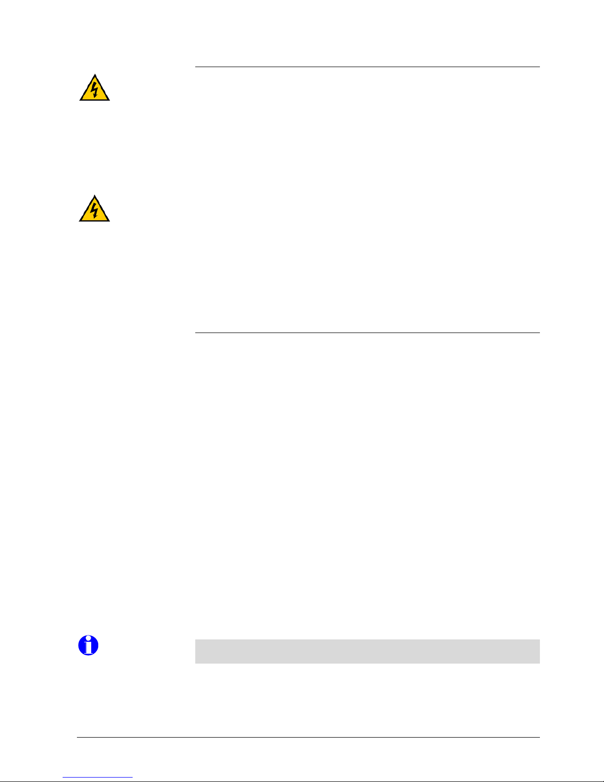
1.6 Document conventions
Information pointing at immediate danger is printed under the heading “Danger” with
the symbol shown in the left margin. Failure to observe this information may result in
severe physical injury or death or severe property damage.
Information under the heading “Warning” is shown with the symbol in the left margin.
Failure to observe this category of information may result in physical injury
and/or property damage.
Information under the heading “Caution” is shown with the symbol in the left margin.
Failure to observe this type of information may result in property damage and/or
loss of data.
Other important information (headed “Important” or “Note”) is shown on a gray
background. Failure to observe this information will not result in any damage.
This relates to additional information important for the safety of personnel and
equipment, or provides details of additional options or technical requirements.
Helpful information to simplify the use of the product for the user.
"Authorized personnel" are persons familiar with installing, mounting, commissioning,
and operating the equipment, and aware of the associated hazards.
Authorized personnel must satisfy the following requirements:
• They must be trained and authorized to switch on, switch off, disconnect, and
ground electric circuits, and to attach warning labels in accordance with the
established safety instructions.
• They must have training in the proper care and use of protective devices in
accordance with all prevailing safety regulations.
• They must be trained in and capable of administering first aid.
CM1N5192en
Danger
Warning
Caution
Important
Note
.
..
.
Tips
Authorized personnel

9/126
Siemens Building Technologies SED2 variable speed drives CM1U5192en
HVAC Products Introduction 01.2002
1.7 Environmental compatibility and disposal
This product was developed and manufactured using materials and processes which
take full account of environmental issues and which comply with our environmental
standards.
Please not the following for disposal at the end of the product life, or in the event of its
replacement:
• For disposal, this product is defined as waste from electrical and electronic
equipment (“electronic waste”); do not dispose of it as household waste. This
applies particularly to the PCB assembly.
• Always use the most environmentally compatible method of disposal, in line with
the state-of-the-art technology in environmental protection, recycling, and waste
management.
Observe all local and applicable laws.
• Always aim for maximum re-use of the basic materials at minimum environmental
stress. Observe any notes on materials and disposal that may be attached to
individual components.
• Use local depots and waste management companies, or refer to your supplier or
manufacturer to return used products or to obtain further information on
environmental compatibility and waste disposal.
The law may mandate special handling of components such as electrolytic
capacitors and LCD panels, or it may be environmentally desirable.
The variable speed drive is delivered in re-usable packaging. Please retain the
packaging for later use or in case you need to return the product to the manufacturer.
General notes
Special electronic
components
Packaging

10/126
Siemens Building Technologies SED2 variable speed drives CM1U5192en
HVAC Products Introduction 01.2002
11/126
Siemens Building Technologies SED2 variable speed drives CM1U5192en
HVAC Products Safety instructions 01.2002
2 Safety instructions
The following warnings and notes on danger are provided for your safety and as a
means of preventing damage to the product or to any components of the connected
machinery. This section contains general warnings, preventive measures, and danger
warnings, which apply to all work on the SED2 variable speed drives. Specific warnings
applicable to particular tasks are summarized at the beginning of each chapter and
repeated throughout the chapter as necessary at the relevant points.
Please read this information carefully, as it is provided for your personal safety,
and to help extend the life of the SED2 variable speed drive and any equipment
connected to it.
Refer to section 1.6 Document conventions for information on the format of warning
notes and as sociated symbols.
2.1 General
♦ This equipment uses hazardous voltages and drives potentially dangerous rotating
mechanical parts. Non-c ompliance with warnings or failure to follow the
instructions in this manual may put lives at risk , or result in severe physical injury,
or serious damage to property/equipment.
♦ Only authorized personnel may work on this equipment. They must first acquaint
themselves with all the safety instructions, and installation and operating
instructions in this manual. Successful and safe operation of this device depends
on its proper handling, installation, commissioning, and operation.
♦ Prevent children and other unauthorized persons from accessing the equipment.
The DC link capacitors remain charged with dangerous voltages for five minutes after
power has been switched off.
Do not open the device for five minutes after switching off the supply voltage.
Use the equipment only for purposes as specified by the manufacturer. Unauthorized
modifications and use of spare parts or accessories not supplied or recommended by
the manuf acturer of this equipment may cause fires, electric shock, and physical injury.
Keep these operating instructions within easy reach of the equipment and make them
available to all users.
2.2 Commissioning
♦ Only authorized personnel trained in the setup, installation, commissioning, and
operation of the product may work on the product and plant.
♦ Only hard-wired mains connections are permissible. Ground the VSD (IEC 536,
Class 1, NEC and other relevant industry standards).
♦ If a residual current device (RCD) is to be used, it must be a type B device.
♦ Do not connect machines with a 3-phase power supply fitted with EMC filters to the
mains via an earth leakage current circuit breaker (ELCB) (see DIN VDE 0160,
section 6.5).
Format of warnings
Warning
Risk of electric shock
Danger
Purpose
Availability of the
operating instructions

12/126
Siemens Building Technologies SED2 variable speed drives CM1U5192en
HVAC Products Safety instructions 01.2002
The following terminals may carry dangerous voltages even when the variable speed
drive is not running:
– Power supply terminals L1, L2, L3.
– Motor terminals U, V, W.
– Link terminals DC-, DC+/B+, DC/R+, B-.
To prevent inductive and capacitive interference, connect the power, motor, and control
cables to the variable speed drive as illustrated and described in section 4.2.1 “EMCcompatible wiring“.
2.3 Operation
♦ SED2 variable speed drives operate at high voltages.
♦ Emergency stop facilities in accordance with EN 60204 IEC 204 (VDE 0113) must
remain operative in all operating modes of the control equipment. Resetting the
emergency stop facility may not cause an uncontrolled or undefined restart.
♦ In cases where faults in the control equipment could cause significant equipment
damage or severe physical injury (e.g., potentially dangerous short circuits), take
additional external precautions or provide facilities to ensure or enforce safe
operation even in the event of a short circuit (e.g., independent limit switches,
mechanical interlocks, etc.).
♦ Certain parameter settings can cause an automatic restart of the variable speed
drive following an fault or supply voltage failure, provided the fault has been
eliminated/acknowledged or the supply voltage has been restored.
♦ The variable speed drive is capable of protecting the motor from overload. (Motor
overload protection in accordance with UL 508C, section 42). See P0610 and
P0335.
♦ Protection against motor overload can be instituted via an external PTC thermistors
(temperature variable conductor) via a special input (Class 14/15, see also section
4.3.12, page 37).
♦ Do not use the variable speed drive as an “Emergency Stop” mechanism
(see EN60204, 9.2.5.4).
2.4 Repairs
♦ Only the Siemens service, repair centers authorized by Siemens, or authorized
personnel fully acquainted with all the warnings and operating procedures as
specified in this manual may repair this equipment.
♦ Replace defective parts or components using parts from the relevant spare parts
list.
Disconnect the power supply before opening the device.
Danger
Caution
Danger
Danger
13/126
Siemens Building Technologies SED2 variable speed drives CM1U5192en
HVAC Products Mechanical installation 01.2002
3 Mechanical installation
3.1 Installing the SED2 after extended storage
Recharge the capacitors in the variable speed drive following an ex tended period of
storage. Remember to calculate the storage time from the date of manufacture,
and not from the date of delivery. The required procedure varies according to the
storage period and is described below.
Period of storage Required action Preparation time
1 year or less Recharging not required. No preparation
1 to 2 years Before issuing the “Run” command, connect the variable speed
drive to the supply voltage for one hour.
1 hour
2 to 3 years Use a variable AC power source.
1. Apply 25% of the input voltage for 30 minutes.
2. Increase the voltage to 50% for a further 30 minutes.
3. Increase the voltage to 75% for a further 30 minutes.
4. Increase the voltage to 100% for a further 30 minutes.
The variable speed drive is then ready for operation.
2 hours
3 or more years Use a variable AC power source.
1. Apply 25% of the input voltage for 2 hours.
2. Increase the voltage to 50% for a further 2 hours.
3. Increase the voltage to 75% for a further 2 hours.
4. Increase the voltage to 100% for a further 2 hours.
The variable speed drive is then ready for operation.
8 hours
3.2 Ambient conditions
IP20 IP54
Min. operating temperature –10 °C –10 °C
Max. operating temperature +40 °C* +40 °C
* Be aware of the potential increase in temperature inside the control cabinet (derating
necessary; refer to the engineering manual).
Max. 95%, non-condensing.
If you want to install the VSD at an altitude of more than 1000 m, derating is required.
(Refer to the engineering manual).
Install the VSD vertically for optimum cooling. Do not obstruct the vents on the VSD.
Additional ventilation may be required if the drive is mounted horizontally. If mounted
vertically, VSDs with a protection standard of IP20 may be installed side by side. A
minimum clearance of 100 mm is necessary above and below the VSD. VSD of class
IP54 require greater clearances. See section 3.3.4 "Mounting SED2 drives with IP54 /
NEMA 12 rating".
Do not install the VSD in the vicinity of powerful sources for electromagnetic radiation.
Temperature
Humidity
Height above sea level
Overheating
Electromagnetic
radiation
14/126
Siemens Building Technologies SED2 variable speed drives CM1U5192en
HVAC Products Mechanical installation 01.2002
Do not install the VSD in an environment containing atmospheric pollutants such as
dust, corrosive gases, etc. Devices subject to protection standard IP20 need additional
protection from dust, atmospheric pollutants, and water.
Do not install the VSD in a location where it might be exposed to repeated shock or
vibration.
3.3 Mounting
The device must be grounded.
♦ Extremely dangerous conditions can arise if you do not correctly ground the
variable speed drive.
♦ To ensure safe operation of the equipment, authorized persons must install and
commission it in full compliance with the notes and warnings set out in these
operating instructions.
♦ Take particular note of general and regional installation and safety regulations
regarding work on sites with dangerous voltages (e.g. EN 50178), and of the
relevant regulations f or the correct use of tools and personal protective equipment.
Dangerous voltages may occur at the following terminals even when the variable speed
drive is not running:
- Power supply terminals L1, L2, L3.
- Motor connection terminals U, V, W, DC-, DC+/B+, DC/R+, B-.
- Link terminals DC-, DC+/B+, DC/R+, B-.
Do not open the device for five minutes after switching off the supply voltage.
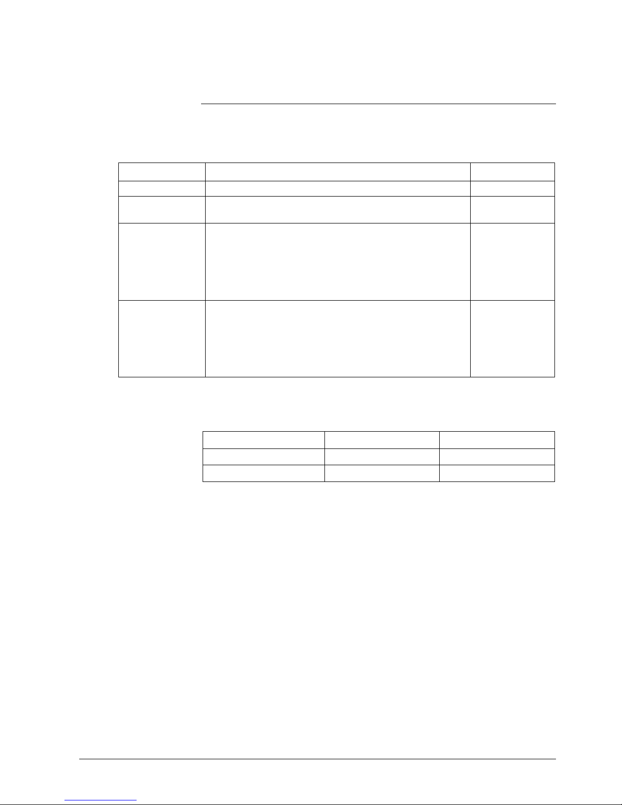
3.3.1 Dimensions of SED2 drives with IP20/NEMA 0 rating
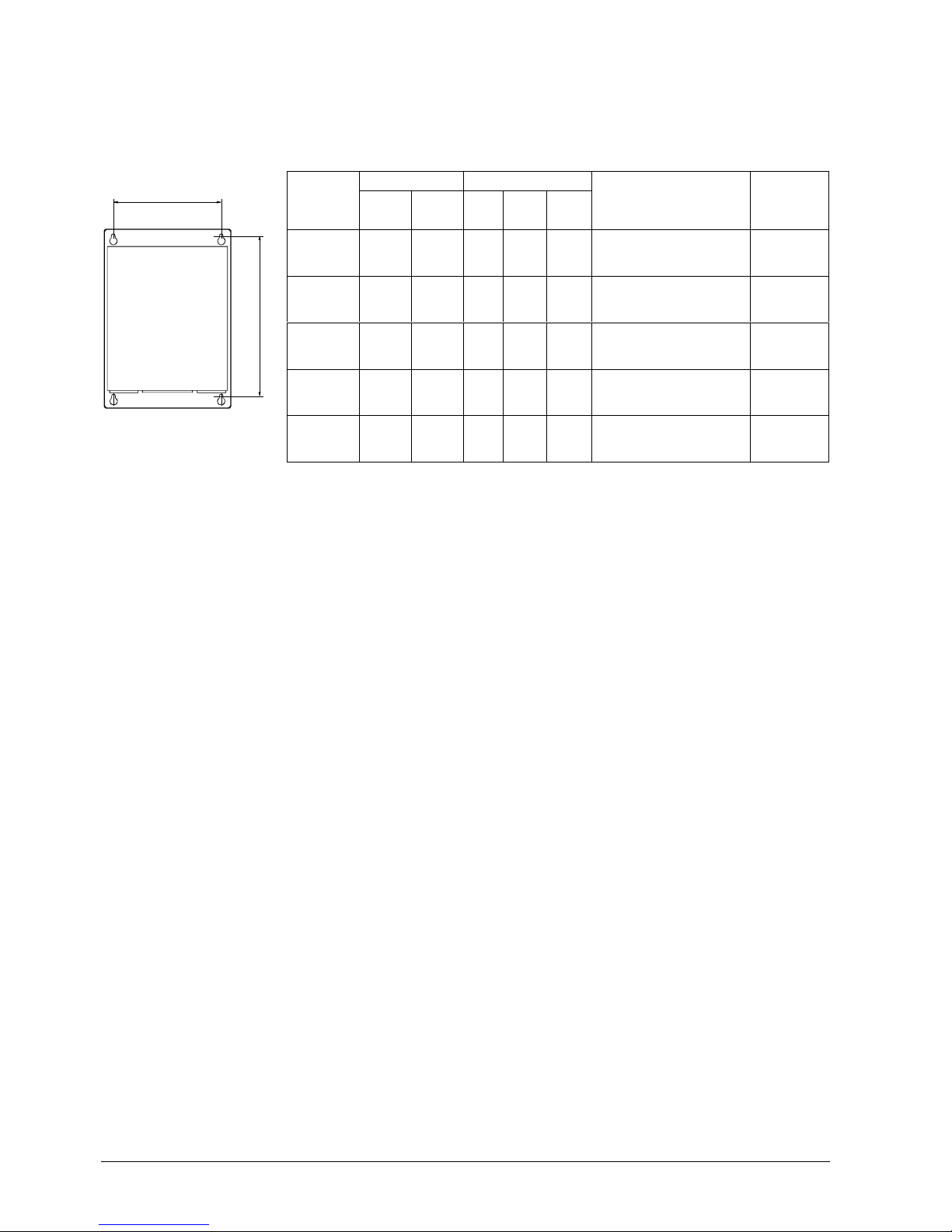
3.3.1.1 Dimensions of SED2 frame sizes A to C
Dimensions
Frame size
AA
1
BCC
1
A
173 200 73 149 192.5
B
202 213 149 172 222.5
C
245 261 185 195 250
A
1
B
C
C
1
5
1
5
2
J
0
1
A
Frame size A
A1
C1
5
1
9
2
J
0
2
B
C
A
Frame sizes B and C
Atmospheric pollution
Shock
Danger
Danger
15/126
Siemens Building Technologies SED2 variable speed drives CM1U5192en
HVAC Products Mechanical installation 01.2002
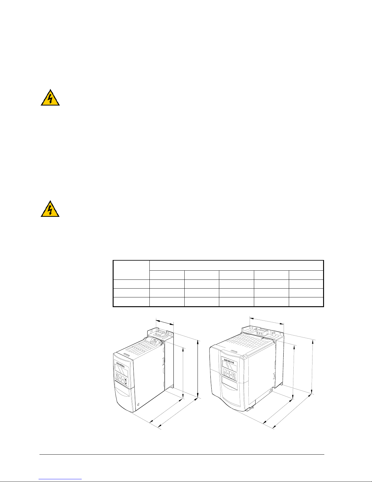
3.3.1.2 Dimensions of SED2 footprint filters for frame sizes A to C
Dimensions in mm
Frame size
ABCGHI JK
A
200 73 43.5 60 160 56 187 22
B
213 149 50.5 138 174 120 200 24
C
245 185 55 174 204 156 232 35
B
I
K
A
J
H
G
C
5192J03
I
K
A
J
H
C
5192J04
B
G
Filter for frame size A Filter for frame sizes B and C
3.3.1.3 Dimensions of SED2 frame sizes D to F
Dimensions in mm
Frame size
ABC
D
520 275 245
E
650 275 245
F
850
(with filter
1150)
350 320
5
1
9
2
J
0
5
A
B
C
16/126
Siemens Building Technologies SED2 variable speed drives CM1U5192en
HVAC Products Mechanical installation 01.2002
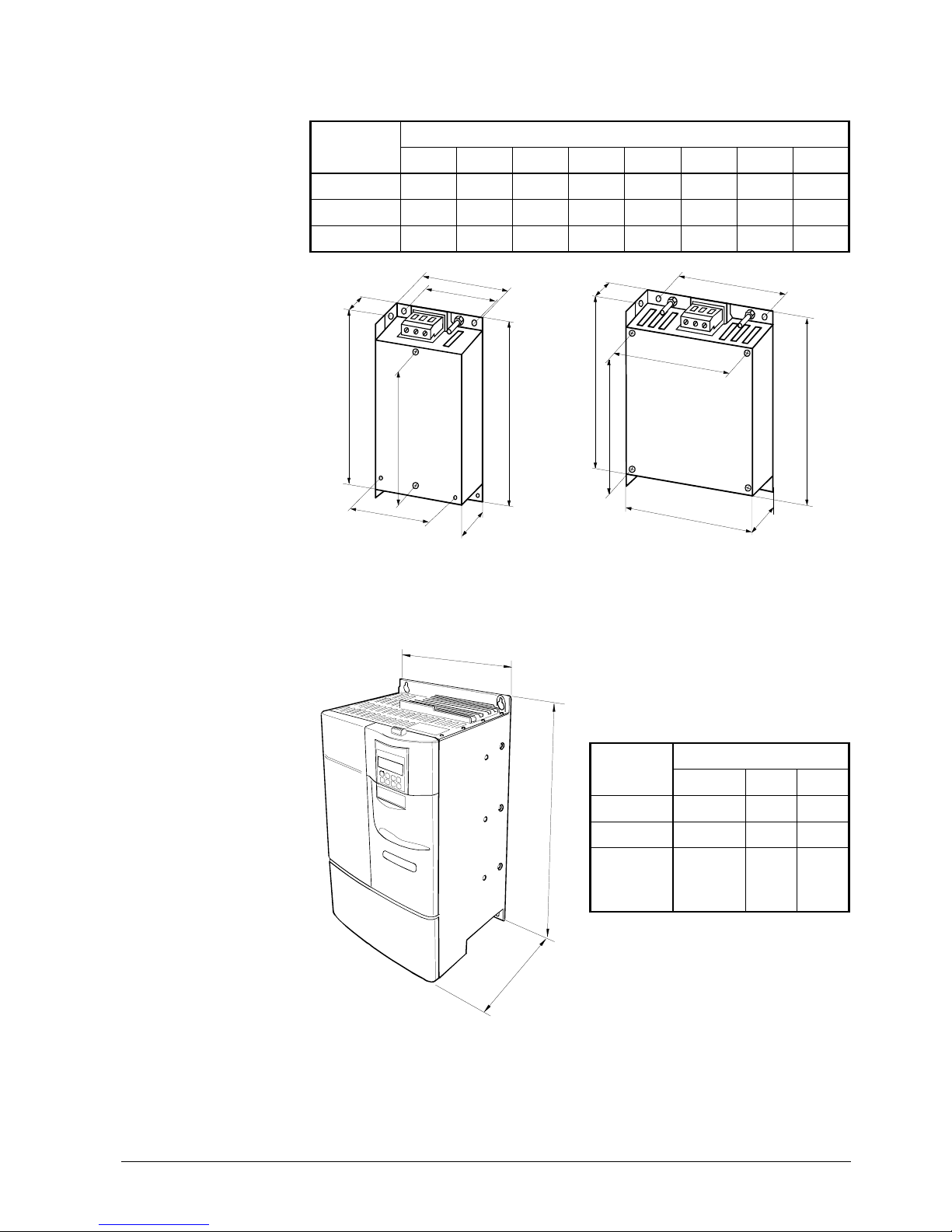
3.3.2 Dimensions of SED2 drives with IP54/NEMA 12 rating
3.3.2.1 Dimensions of SED2 frame sizes B and C
Dimensions in mm
Frame size
ABC
B
385 270 268
C
606
350
284
B
C
A
5
1
9
2
J
0
6
3.3.2.2 Dimensions of SED2 frame sizes D to F
Dimensions in mm
Frame size
ABC
D
685 360 353
E
885 360 453
F
1150 450 473
A
B
C
5
1
9
2
J
0
7

17/126
Siemens Building Technologies SED2 variable speed drives CM1U5192en
HVAC Products Mechanical installation 01.2002
3.3.3 Mounting SED2 drives with IP20/NEMA 0 rating
H
H
H
W
W
Frame size A
Frame size B
Frame sizes D, E and F
5192M01en
Hole spacing
Frame size
H in mm W in mm
Mounting materials
Tightening
torque
A
160
* 187
-
*56
2 x M4 bolts
2 x M4 nuts
2
x M4 spring lock washers
2 x M4 washers
or mounting on DIN rail
2.5 Nm
B
174
* 200
138
* 120
4
x M4 bolts
4 x M4 nuts
4
x M4 spring lock washers
4
x M4 washers
2.5 Nm
C
204
* 232
174
* 156
4
x M5 bolts
4 x M5 nuts
4
x M5 spring lock washers
4
x M5 washers
3.0 Nm
D 486 235
4
x M8 bolts
4 x M8 nuts
4
x M8 spring lock washers
4
x M8 washers
13 Nm
E
616.4 235
4
x M8 bolts
4 x M8 nuts
4
x M8 spring lock washers
4
x M8 washers
13 Nm
F
810
1110withfilter
300
4
x M8 bolts
4 x M8 nuts
4
x M8 spring lock washers
4
x M8 washers
25 Nm
* with footprint filter
A minimum clearance of 100 mm is required above and below each variable speed
drive.
Drilling plan for SED2
IP20
Note
.
..
.
18/126
Siemens Building Technologies SED2 variable speed drives CM1U5192en
HVAC Products Mechanical installation 01.2002
3.3.4 Mounting SED2 drives with IP54 / NEMA 12 rating
Hole spacing Clearance (mm)
Frame size
H (mm) W(mm) Top BottomSide
Mounting materials
Tightening
torque
B 342.8 230 150 150 100
4xM6 bolts
4xM6 washers
4xM6 spring lock washers
5Nm
C 564 312.7 150 150 100
4xM6 bolts
4xM6 washers
4xM6 spring lock washers
5Nm
D 647 310 200 200 150
4xM8 bolts
4xM8 washers
4xM8 spring lock washers
13 Nm
E 847 310 200 200 150
4xM8 bolts
4xM8 washers
4xM8 spring lock washers
13 Nm
F 1112 400 300 250 150
4xM8 bolts
4xM8 washers
4xM8 spring lock washers
20 Nm
Drilling plan for SED2
IP54
W
H
5192M02
19/126
Siemens Building Technologies SED2 variable speed drives CM1U5192en
HVAC Products Electrical installation 01.2002
4 Electrical installation
The VSD must be grounded.
♦ To ensure safe operation of the equipment, authorized persons must install and
commission it in full compliance with the notes and warnings set out in these
operating instructions.
♦ Take particular note of general and regional installation and safety regulations
regarding work on sites with dangerous voltages (e.g. EN 50178), and of the
relevant regulations f or the correct use of tools and personal protective equipment.
♦ The cross-section of the ground bonding conductor must be at least equal to that of
the mains connection cables.
Dangerous voltages may occur at the following terminals even when the
variable speed drive is not running:
- Power supply terminals L1, L2, L3.
- Motor terminals U, V, W, DC+, DC-.
- Link terminals DC-, DC+/B+, DC/R+, B-.
After switching off the supply voltage, wait at least 5 minutes before starting any
installation or service work.
4.1 General
4.1.1 Maximum length of motor cables
The performance data given in the specifications cannot be guaranteed if the motor
cables exceed the following lengths: 50 m for shielded cables
100 m for unshielded cables
For devices featuring EMC filters, the maximum cable length is 25 m. For cables
shorter than > 25 m, the EMC guideline for filtered devices does not apply.
If you connect several motors to one VSD, the individual motor lines must be added to
the total line length.
4.1.2 Operation with ungrounded systems
SED2 variable speed drives with a protection standard of IP20 operate in ungrounded
systems, and remain in operation when an input phase connects to ground. In the
event of an output phase with a ground fault, the SED2 switches off and displays
message F0001.
SED2 drives with a protection standard of IP54/NEMA 12 cannot be operated in
ungrounded systems.
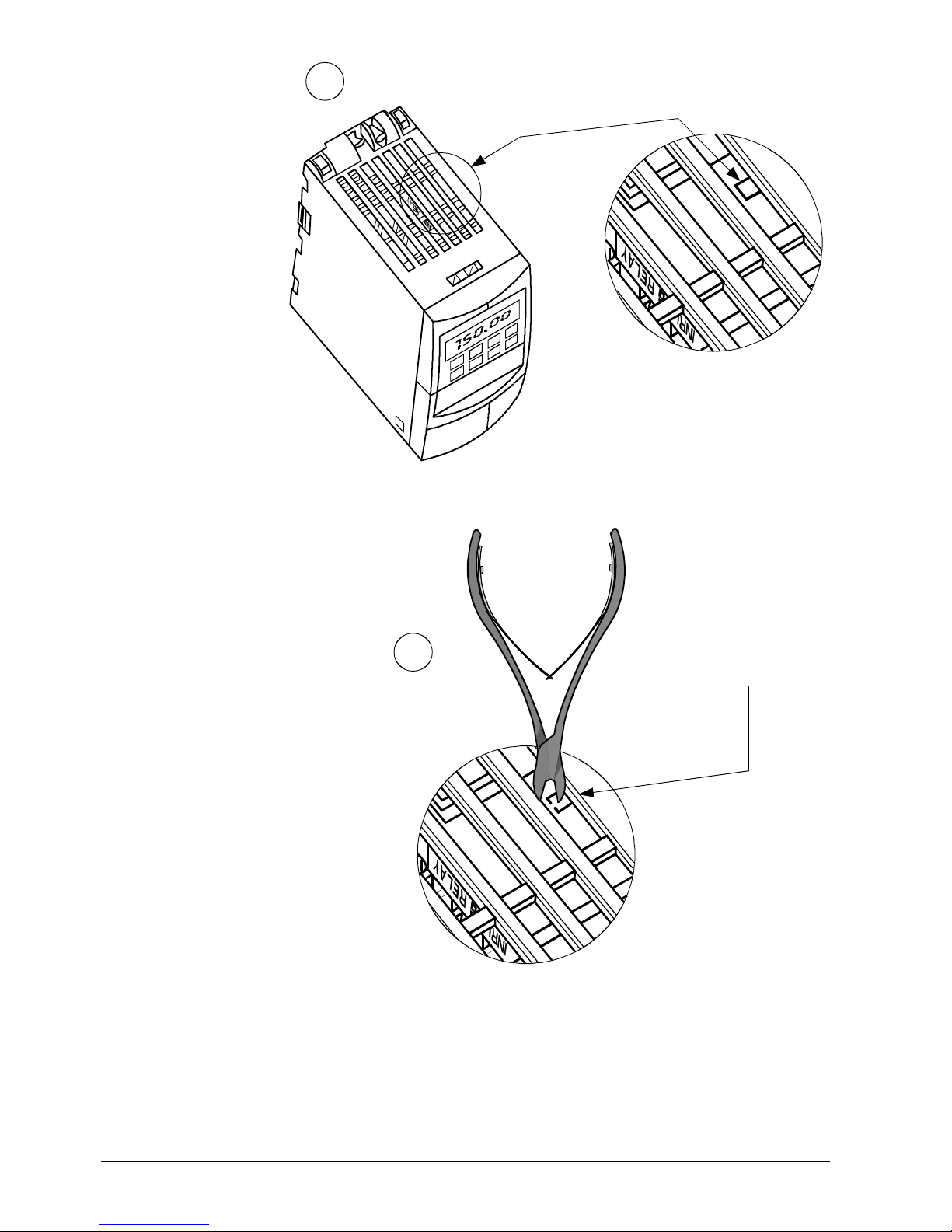
4.1.2.1 Precautions for ungrounded systems (IT protective systems)
In ungrounded systems, remove the Y capacitor, or break the connections to this
capacitor and integrate an output choke. The following procedure shows how to remove
or disconnect the capacitor.
Operation in ungrounded systems is possible only using the SED2, IP20, without
filter.
Danger
Danger
Note
.
..
.
IP20/NEMA 0
IP54/NEMA 12
Important
20/126
Siemens Building Technologies SED2 variable speed drives CM1U5192en
HVAC Products Electrical installation 01.2002
LK 700
1
2
5192Z01
Disconnecting the Y
capacitor in SED2
drives, frame size A

21/126
Siemens Building Technologies SED2 variable speed drives CM1U5192en
HVAC Products Electrical installation 01.2002
1
2
3
5192Z02
2021 22 2324 25
29 3017 26 27 2812 13 14 15 16
10 11678912345
ON
12
PE
5192Z03en
Torx driver T20
M4
Screw
Disconnecting the Y
capacitor in SED2
drives, frame sizes
BandC
Disconnecting the Y
capacitor in SED2
drives, frame sizes
DandE
22/126
Siemens Building Technologies SED2 variable speed drives CM1U5192en
HVAC Products Electrical installation 01.2002
4.1.3 Operation with a residual current device (RCD)
M6
T30
Torx screwdriver
5192J17en
If a residual current device (also referred to as a GLCI or RCCB) is connected, the VSD
operates without unwanted interruptions under the following conditions:
þ An RCD type B must be used.
þ The RCD must have a threshold current of 300 mA.
þ The neutral conductor in the system must be grounded.
þ Each RCD supplies only one VSD and no other consumers.
þ The output cables must not exceed 50 m in length (shielded) or 100 m
(unshielded).
Disconnecting the Y
capacitor in SED2 drives,
framesizeF
23/126
Siemens Building Technologies SED2 variable speed drives CM1U5192en
HVAC Products Electrical installation 01.2002
4.2 EMC-compatible installation
The SED2 VSDs operate in environments where they may be exposed to high levels of
electromagnetic interference (EMI). Normally, good installation practices ensure safe
and interference-free operation. However, should problems associated with EMI occur,
follow the guidelines below:
Ø
Ensure good electrical contact between the mounting plate and the metal housing
of the VSD via the mounting screws.
Ø
Use serrated lock washers and electrically conductive mounting plates.
Ø
If a footprint EMC filter is used, fit it under the VSD and ground it via the metal
backplate. When connecting the EMC filter to the inputs of the VSD, use shielded
cables and make sure that they are correctly grounded using cable clamps.
4.2.1 EMC-compatible wiring
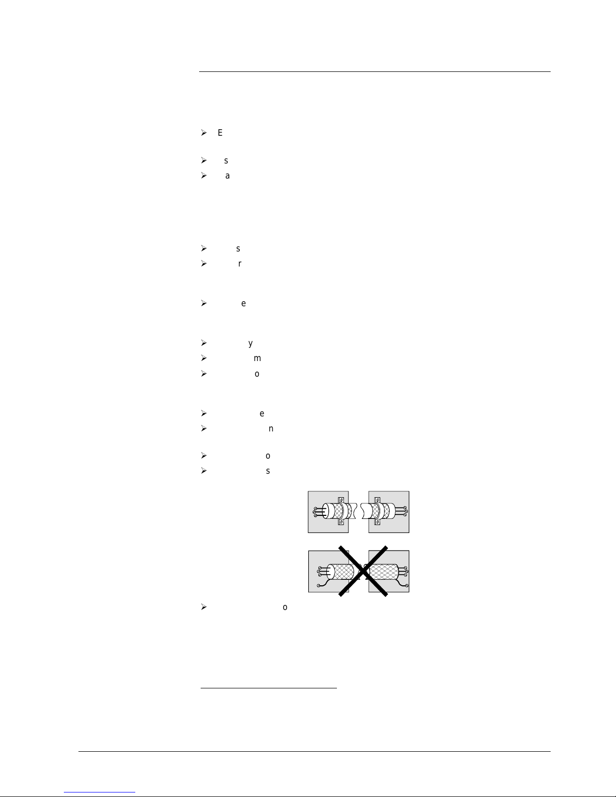
Ø
Use shielded cables also inside control cabinets.
Ø
Ensure that all equipment in the control cabinet is properly grounded. Thus, make
sure that all equipment is connected by short, thick grounding conductors to a
common grounding point (flat ribbon lines are best) or bus bar.
Ø
Ensure that any control equipment (e.g. PLC or BACS1) connec ted to a VSD is
connected with a short, thick cable to the same ground or grounding point as the
variable speed drive itself.
Ø
Use only shielded motor and control cables. The shielding must be continuous.
Ø
Connect motor and control cables to ground at both ends.
Ø
Lay control, mains, and motor cables separately by routing them in separate cable
ducts and maintaining a minimum clearance of at least 200 mm (see diagram
below). If you must cross cables, run them at an angle of 90° if possible.
Ø
Motor cables should be as short as possible and should not exceed 25 m.
Ø
Connect the neutral conductor for the motors controlled by the variable speed
drives directly to the ground connection (PE) of the associated VSD.
Ø
Use flat ribbon cables, as they have a lower impedance at high frequencies.
Ø
Avoid pigtails. Use only grounding clamps to bond the screen (see diagram below).
5191Z01
Ø
Check that the contactors in the control cabinet are suppressed—either with RC
circuits for AC contactors, or flywheel diodes for DC contactors—and fit the
suppressors to the coils. Varistor surge voltage protectors are also effective. This is
important if the contactors are controlled by the variable speed drive relay.
1
SPS: Programmable controllers
BACS: Building automation and control system; sometimes incorrectly referred to as BMS (building
management system)
24/126
Siemens Building Technologies SED2 variable speed drives CM1U5192en
HVAC Products Electrical installation 01.2002
L1
L2
L3
PE
BMS
SED2
wvu
5192Z04en
Min. 16 mm²
(4 AWG)...
compensatingcable
Install all cables on the
same side of the plate
Min.200 mm
(7.8 inches)....
between
control cables,
motor cables and
mains cables
Motor cable
Mains power supply
Min.10 mm² (6 AWG)...
PE: min.10 mm² (6 AWG)...
Remove cable
insulation
Controlcables
Grounding rail
Motor
5192J10
1
L1
L2
L3
2
6
3
4
5
1 Incoming mains cable
2 Control cable
3 Motor cable
4 Footprint filter
5 Metal backplate
6 Use suitable cable clamps to
ensure good conductive
contact between the shield of
the motor and control cables
and the metal backplate
7 Connect the motor cable
shield to
.
Cable routing for frame
sizes A to C, with
footprint filter
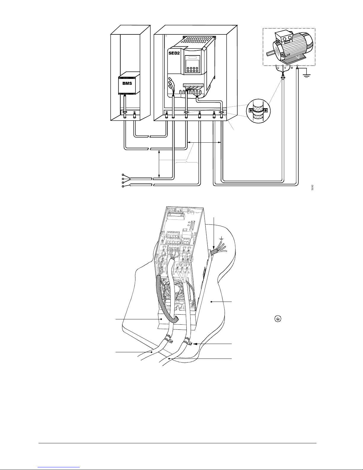
25/126
Siemens Building Technologies SED2 variable speed drives CM1U5192en
HVAC Products Electrical installation 01.2002
Shield connected
with tube clips
Motor cable
Incoming mains voltage
5192J21us
4.3 Mains and motor connections
Warning and safety instructions
♦ Check that the VSD and motor are correctly sized for the supply voltage. Check
that the VSD corresponds to at least the motor output.
♦ Check that the mains cables are correctly sized for the anticipated use.
♦ Check that appropriate circuit breakers or fuses exist between the mains and the
variable speed drive.
Never use high voltage insulation test equipment on any cables connected to the
variable speed drive.
♦ Always isolate the power cables before connecting them to the VSD.
♦ Check that the terminal cover was replaced properly after connecting the power
and motor cables.
♦ Never switch on the VSD with the cover open.
♦ Always use ins ulated tools when working on the incoming power supply and the
motor terminals.
Cable routing for frame
sizes D to F, IP20 with
EMC filter
Caution
Warning
Danger
26/126
Siemens Building Technologies SED2 variable speed drives CM1U5192en
HVAC Products Electrical installation 01.2002
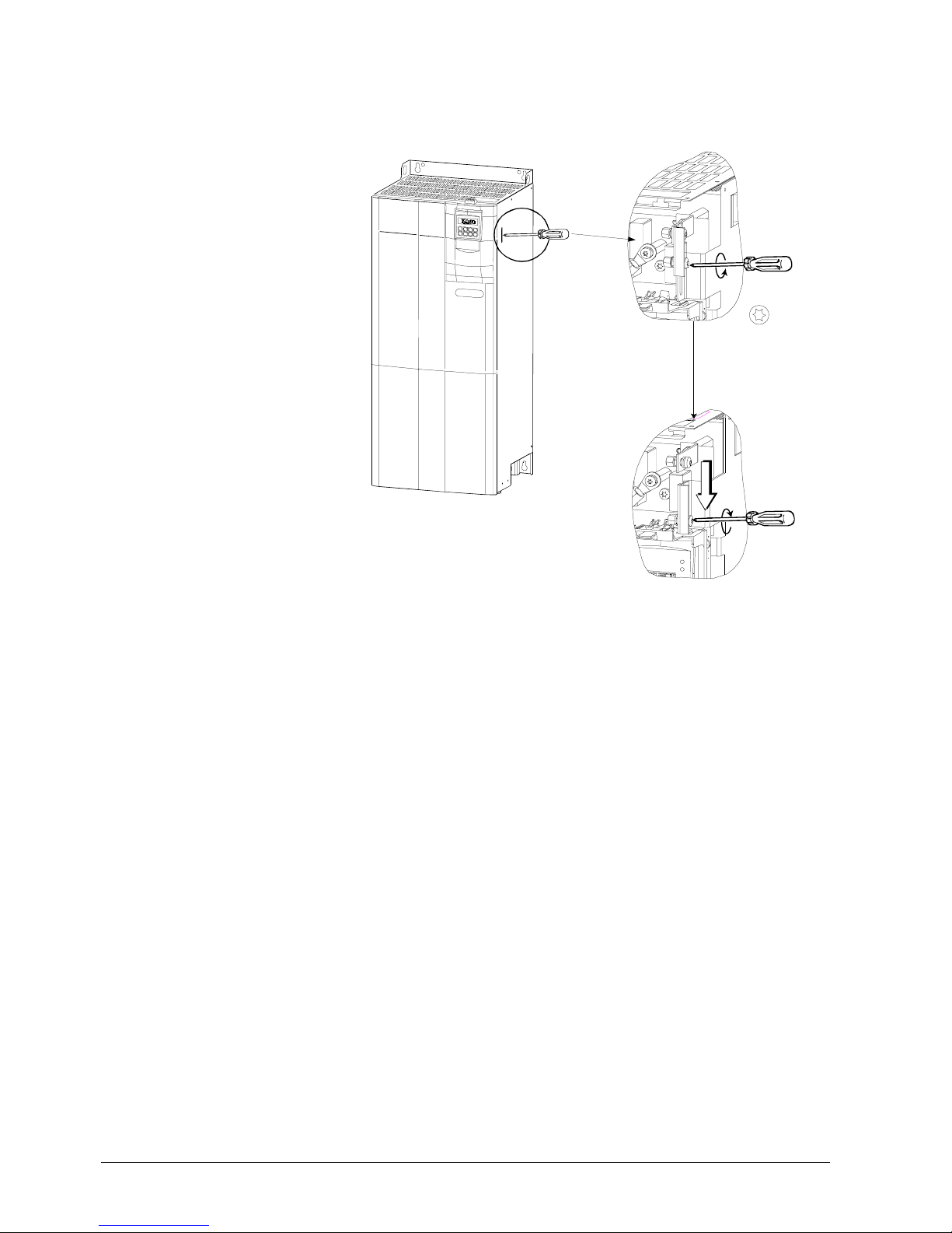
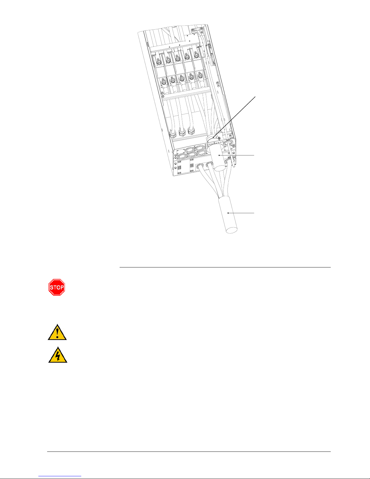
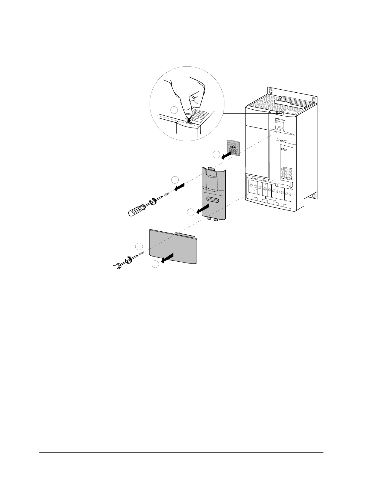
4.3.1 Access to connection terminals: Frame size A
To access the mains and motor terminals, first remove the operator panel, cover, and
I/O module as illustrated below.
5192J08
1
5192J09
1
5192J16
2
1
Removing the operator
panel (BOP or AOP)
Removing the terminal
cover of the I/O module
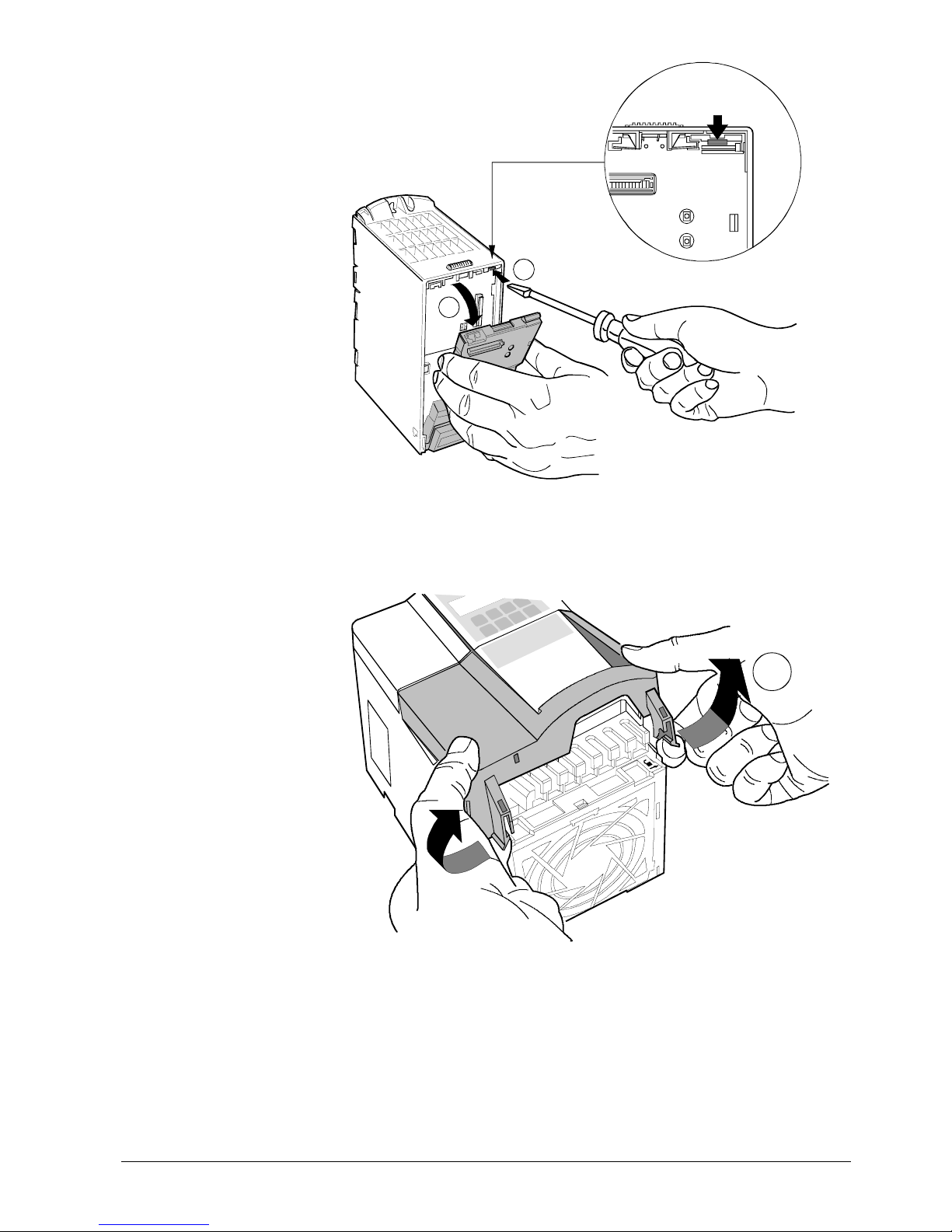
27/126
Siemens Building Technologies SED2 variable speed drives CM1U5192en
HVAC Products Electrical installation 01.2002
1
5192J20
2
4.3.2 Access to connection terminals: Frame sizes B and C
1
5192J12
Removing the
I/O module
Removing the cover of the
mains and motor
terminals
28/126
Siemens Building Technologies SED2 variable speed drives CM1U5192en
HVAC Products Electrical installation 01.2002
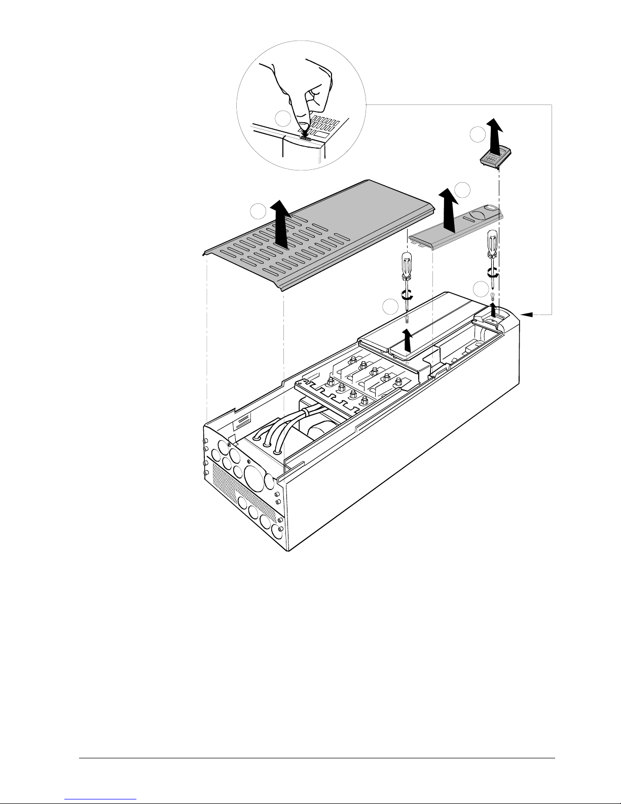
4.3.3 Access to connection terminals: Frame sizes D to F IP20
Refer to the relevant paragraph in Access to connection terminals: Frame size A.
3
1
2
5
6
4
5
1
9
2
J
1
3
Removing the operator
panel (BOP or AOP)
Opening the housing:
Frame sizes D and E
29/126
Siemens Building Technologies SED2 variable speed drives CM1U5192en
HVAC Products Electrical installation 01.2002
2
3
4
1
5
1
9
2
J
1
4
5
6
Opening the housing:
FramesizeF
30/126
Siemens Building Technologies SED2 variable speed drives CM1U5192en
HVAC Products Electrical installation 01.2002
4.3.4 Power and motor terminals: Frame sizes A to F
(Ground)
PE
(Ground)
L1
L2
L3
DC+ DC-
UVW
5192Z05
DC
R+
B-
UVWDC- DC+B+DCR+B-
L3
L2
L1
PE
5192Z06
L1 L2 L3 DC- DC+B+DC
R+
B- U V W
PE
5192Z07
Terminal layout: Frame
size A
Terminal layout:
Frame sizes B and C
Terminal layout:
Frame sizes D and E
 Loading...