

Siemens SE25M575GB series Repair Instructions

R
R
R
E
E
E
P
P
P
A
A
A
I
I
I
R
R
R
I
I
I
N
N
N
S
S
S
T
T
T
R
R
R
U
U
U
C
C
C
T
T
T
I
I
I
O
O
O
N
N
N
Dishwasher
815_58300000003806_ara_en_e.doc – 30.01.12 Seite 1 von 67
1 SAFETY........................................................3
2 INSTALLATION............................................4
2.1 Aligning the appliance........................................................ 4
2.2 Electrical connection..........................................................4
2.3 Water connection................................................................4
3 OPERATION.................................................5
3.1 Module view.........................................................................5
3.2 Display.................................................................................5
3.3 Pushbuttons / Additional functions .................................. 5
3.4 Pushbuttons / Programme selection................................. 6
3.5 Special functions ................................................................ 7
4 COMPONENTS.............................................9
4.1 Module ................................................................................. 9
4.2 Actuator.............................................................................13
4.3 Aqua sensor (optional).....................................................14
4.4 Aqua Stop valve................................................................15
4.5 NTC .................................................................................... 16
4.6 Regeneration / drainage valve......................................... 17
4.7 Raw water valve ................................................................ 17
4.8 Salt and rinse-aid indicators (optional)........................... 18
4.9 Optical low rinse-aid sensor (optional)...........................19
4.10 Dispenser...........................................................................20
4.11 Instantaneous water heater.............................................. 21
4.12 Water softening system................................................... 22
4.13 Detergent-solution pump................................................. 23
4.14 Level sensor with safety function................................... 24
4.15 Filter system ..................................................................... 25
4.16 Spray system.................................................................... 26
4.17 Rinsing and pumping system.......................................... 27
4.18 Door spring ....................................................................... 28
4.19 Circulation pump (SICASYM) .......................................... 29
4.20 Water inlet with heat exchanger...................................... 30
4.21 Water points (optional)..................................................... 32
5 FUNCTIONS................................................33
5.1 3 in 1 detergents............................................................... 33
6 REPAIR.......................................................34
6.1 Module............................................................................... 34
6.2 Display foil ........................................................................ 36
6.3 Replacing the Aqua Stop valve ....................................... 38
6.4 Worktop (optional)............................................................ 39
6.5 Removing and installing dispenser ................................ 40
6.6 Circulation pump (SICASYM) .......................................... 41
6.7 Detergent-solution pump................................................. 43
6.8 Removing and installing hinge........................................ 44
6.9 Water softening system................................................... 46
6.10 Instantaneous water heater ............................................. 47
6.11 Replacing the door seal................................................... 48
6.12 Diagnosis aids .................................................................. 49

815_58300000003806_ara_en_e.doc – 30.01.12 Seite 2 von 67
7 FAULT DIAGNOSTICS...............................50
7.1 Controller / module...........................................................50
7.2 Mechanical faults..............................................................51
7.3 Draining .............................................................................52
7.4 Odour.................................................................................53
7.5 Noises................................................................................54
7.6 Rinsing result....................................................................55
7.7 Drying result...................................................................... 64
7.8 Circulation pump ..............................................................65
8 TECHNICAL SPECIFICATIONS ................66
8.1 General technical specifications..................................... 66
8.2 Consumption rates ........................................................... 67
815_58300000003806_ara_en_e.doc – 30.01.12 Seite 3 von 67
1 SAFETY
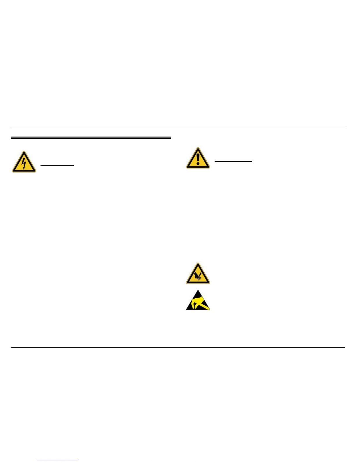
DANGER
Repairs may be carried out by a qualified electrician only!
The user may be put at risk and injured by improper repairs!
To prevent electric shocks, always comply with the following
instructions:
► If the appliance is faulty, the housing or frame may be live!
► Electric shock may occur if live components are touched
inside the appliance!
► Before commencing repairs, disconnect the appliance from
the power supply!
► If tests have to be performed while the appliance is live,
always use a residual-current-operated circuit-breaker!
► The protective conductor resistance must never exceed the
values specified in the standard! The protective conductor is
crucial for personal safety and appliance function.
► When repairs are complete, conduct a test in accordance with
VDE 0701 or the corresponding national regulations!
► When repairs are complete, perform a function and leak test.
WARNING
Comply with the following instructions:
If conducting the test in accordance with VDE 0701 via the connector,
the heater (instantaneous water heater) must be tested directly for
insulation faults due to all-pole disconnection (relays; pressure switch)
or the differential current must be measured on the appliance!
If replacing the dispensing device and the pump sump, beware of
sharp edges in the area of the stainless-steel modules.
Before commencing repairs, always disconnect the appliance from the
power supply! If tests have to be performed while the appliance is live,
always use a residual-current-operated circuit-breaker!
Sharp edges: Wear protective gloves.
Electrostatic sensitive devices!
Please observe handling regulations.
815_58300000003806_ara_en_e.doc – 30.01.12 Seite 4 von 67
2 INSTALLATION
2.1 Aligning the appliance
To ensure a perfect locking function and prevent leaks in the area of
the door, the appliance must be aligned precisely via the heightadjustable feet. If the appliance is integrated, the middle rear heightadjustable foot can be adjusted from the front.
When installing the appliance, please note:
► Using the height-adjustable feet, raise the appliance
until the housing touches the worktop.
► The installation instructions (drilling template) are
required for attaching the furniture front to integrated
and fully integrated appliances.
► The tensile force of the door springs in integrated
and fully integrated appliances can be adjusted to the
weight of the furniture door (See Door spring point).
► To prevent injury, a side cover 481271 can be fitted
near the hinges of appliances which are fitted to the
end, built in or under or are free-standing.
2.2 Electrical connection
Connect the appliance to a correctly installed earthed socket only.
Comply with the specifications on the rating plate.
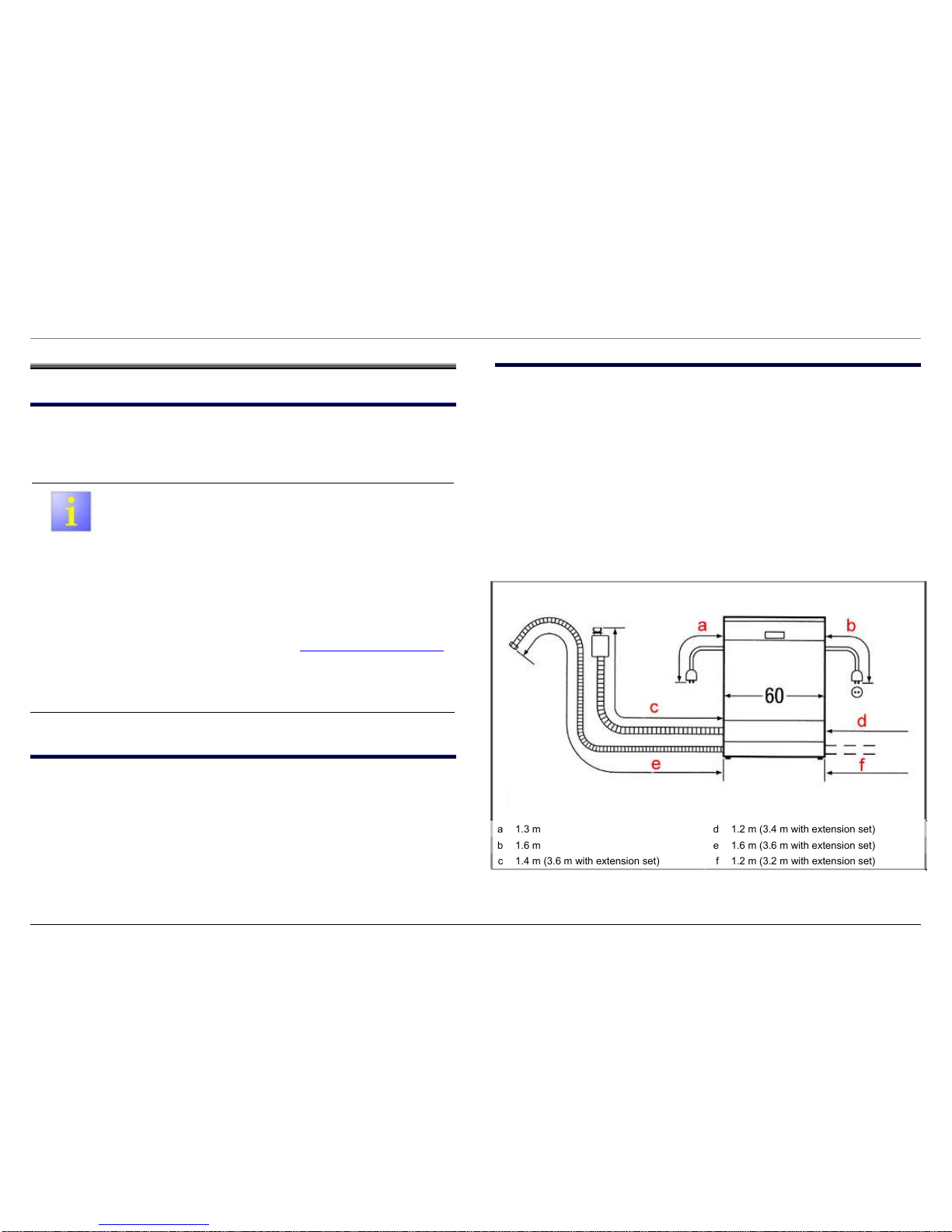
2.3 Water connection
If the appliance is connected to the drain with the standard hose
length, the max. permitted height from the floor is 90 cm. If the
drainage hose is extended, a max. height of 80 cm must not be
exceeded. The water connection (3/4 inch) requires a conventional
water line with a water pressure of at least 0.5 bar (0.5 at.) (when the
tap is turned on, the water flow rate must be more than 8 l/min.). If the
water pressure is more than 10 bar (10 at.), a pressure reducing valve
must be installed.
The appliances can be connected to warm water up to 60 °C.
However, it is recommended to connect the appliance to cold water
(better drying
and washing results).
Connection dimensions for all 60 cm dishwashers
a 1.3 m d 1.2 m (3.4 m with extension set)
b 1.6 m e 1.6 m (3.6 m with extension set)
c 1.4 m (3.6 m with extension set) f 1.2 m (3.2 m with extension set)
815_58300000003806_ara_en_e.doc – 30.01.12 Seite 5 von 67
3 OPERATION
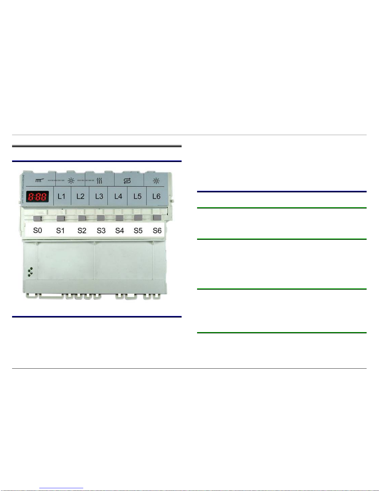
3.1 Module view
3.2 Display
The display consists of a 3-digit 7-segment display. The expected remaining running time is displayed in hours and minutes.
The remaining running time is recalculated at the end of the heating
positions. If deviations occur on account of the aqua sensor decisions,
water supply temperature, number of utensils, etc., the indicated
remaining running time is corrected in these positions. Time jumps of
up to 60 minutes may occur. At the start of the programme the
remaining running time is displayed which was required by this
programme the last time.
3.3 Pushbuttons / Additional functions
3.3.1 Timer programming (TP)
The timer programming button enables the start time to be delayed by
up to 24 h
3.3.2 Soaking (optional)
The “soaking” button can also be selected for any rinse programme. If
the button is pressed, an additional prerinse occurs and the bottom
basket is heated to 55°. This causes the running time to be extended
by approx. 20 min. Recommended for mixed utensils (top basket: fragile
utensils / bottom basket: very dirty non-fragile utensils).
3.3.3 Top basket (optional)
The top basket button must be pressed if only the top basket is to be
rinsed. The water points are positioned for top basket rinsing throughout the rinse cycle. However, the programme sequence is the same
as for alternate rinsing.
3.3.4 Time reduction (optional)
The time reduction button can also be selected for any programme.
When the button is pressed, the circulation and drying times and
therefore the rinsing and drying performance are reduced

815_58300000003806_ara_en_e.doc – 30.01.12 Seite 6 von 67
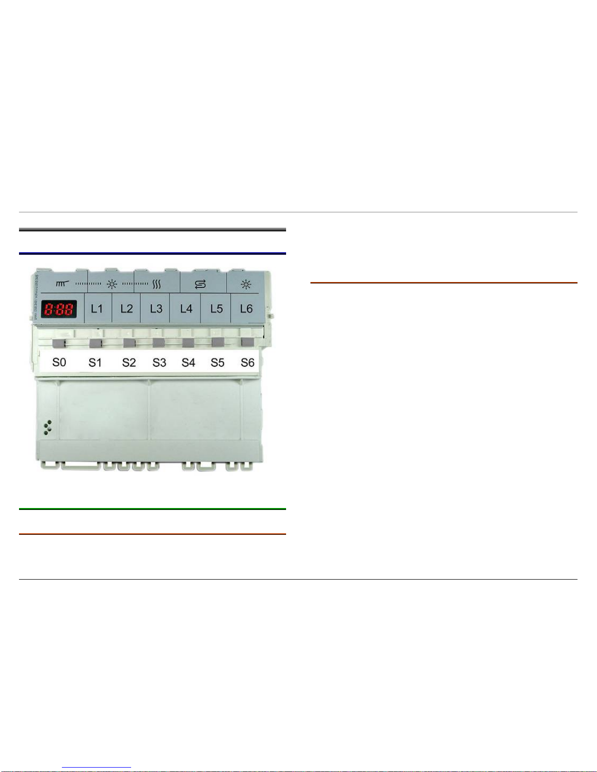
3.3.5 Half load (optional)
The “Half Load” function reduces water consumption and the running
time. Basically this is achieved by passing over the prerinse and the
second intermediate rinse cycle.
3.3.6 Vario speed (optional)
The Vario speed function reduces the programme running time with
a higher water and energy consumption. This is achieved by using
more water in the rinse cycle and with water points with two-basket
function.
3.4 Pushbuttons / Programme selection
3.4.1 Intensive 70°
The programme consists of a prerinse at 50°, wash cycle at 70°, two
intermediate rinse cycles, final rinse at 70° and a drying cycle. Please
ensure that the utensils are washed in the bottom basket only until the
temperature is reached.
3.4.2 Auto 55°–65° (depending on model)
In the auto programme the Aqua sensor decides not only on a water
change after the prerinse, but it also specifies the temperature of the
wash cycle and the number of intermediate rinse cycles. If clean water
is detected in the prerinse, the water from the prerinse is also used in
the wash cycle, a wash cycle at 65°, one intermediate rinse cycle and
a drying cycle. If dirty water is detected in the prerinse, the prerinse
cycle runs, a wash cycle at 51°, two intermediate rinse cycles and
a drying cycle.
3.4.3 ECO 50°
The programme consists of a wash cycle at 50°, one intermediate
rinse cycle, final rinse at 66° and a drying cycle. The Aqua sensor
is not active in this programme. Please ensure that the utensils are
washed in the bottom basket only until the temperature is reached.
3.4.4 Gentle 40°
The programme consists of a prerinse cycle, a wash cycle at 40°, one
intermediate rinse cycle, final rinse at 55° and a drying cycle.
3.4.5 Quick 35°
The programme consists of a wash cycle at 35°, one intermediate
rinse, final rinse at 55° without drying. The Aqua sensor is not active
in this programme.
3.4.6 Prerinse
The programme consists of a prerinse only. The Aqua sensor is not
active in this programme.

815_58300000003806_ara_en_e.doc – 30.01.12 Seite 7 von 67
3.5 Special functions
3.5.1 Setting the hardness range
Hold down the S5 button and switch on the appliance. The set value is
indicated on the digital display. The set value increases by one each
time the S5 button is pressed. When the value H:07 is reached, the
display jumps back to H:00. While the hardness range is being set,
the L5 LED flashes. If the appliance is switched off, the value is
saved. (Table below)
°dH °fH °Clarke mmol / l Salt
consumption in
g per rinse cycle
Set value
0–3 0–6 0–4 0–0.6 0 H 00
4–6 7–11 5–8 0.7–1.1 2 H:01
7–9 12–16 9–11 1.2–1.6 4 H:02
10–12 17–21 12–15 1.7–2.1 6 H:03
13–16 22–29 16–20 2.2–2.9 9 H:04
17–21 30–37 21–26 3.0–3.7 14 H:05
22–30 38–54 27–38 3.8–5.4 27 H:06
31–50 55–89 39–62 5.5–8.9 54 H:07
Standard setting = H:04
3.5.2 Setting intensive drying
Hold down the S4 button and switch on the appliance.
S:00
is indicated
on the digital display. If the S4 button is pressed again,
S:01
is displayed
and intensive drying is switched on. When the appliance is switched off,
the value is saved. If intensive drying is activated, the temperature is increased by 3 K in the final rinse to improve the drying result.
3.5.3 De-activating the low rinse-aid indicator
Hold down the S0 button and switch on the appliance. I:01 is indicated
on the digital display. If the S0 button is pressed again, I:00 is displayed and the rinse-aid refill indicator is de-activated.
I:00 = switched off
I:01 = switched on
When the appliance is switched off, the setting is saved. If the low
rinse aid indicator is de-activated, the temperature is increased by 3 K
in the final rinse to improve the drying result. (see also 3 in 1
detergent detection)
3.5.4 Programme reset
When the appliance is switched on, press the S4 and S6 buttons for
3 sec. The programme is reset (3x intermittent pumping, then pumping
for approx. 30 sec.).
Then close the detergent dispenser to reset the dispenser.

815_58300000003806_ara_en_e.doc – 30.01.12 Seite 8 von 67
3.5.5 Button lock (optional)
The button lock prevents a programme from being unintentionally
selected.
► Activation:
Switch on appliance and select programme
Hold down S5 button for at least 4 sec.
CL is displayed
If a button is pressed while the programme is running, CL is displayed.
The programme cannot be reset.
► Deactivation:
Hold down S5 button for at least 4 sec. until CL goes out
► When the programme ends, the button lock is
deactivated. If there is a power failure, the button
lock is activated
► Whenever a programme is started, the button lock
must be re-activated
815_58300000003806_ara_en_e.doc – 30.01.12 Seite 9 von 67
4 COMPONENTS
4.1 Module
4.1.1 Filling logic
4.1.1.1 Tap turned off
If the level is not reached in the filling position within 6 minutes (f1 is not
actuated), the programme is terminated (1 min. pumping → restart).
This process can be repeated a total of 3x. If the filling level is still not
reached, the filler valve continues to be actuated until the level switch
is actuated.
The display stops 6 min. after the start of the programme until the
level is reached.
4.1.1.2 Level switch is not actuated
If the level switch (f1) does not switch over in the filling position, the
filler valve is actuated until the safety level is reached. The safety
switch switches the detergent-solution pump on and switches the filler
valve off. When the safety switch has switched back, the filler valve is
re-actuated. This results in a switchover between pumping and filling.
If the level switch (f1) does not switch over within 6 min., the programme is terminated (1 min. pumping). The filling step is then
restarted. This process can be repeated a total of 3x. As a result, an
attempt is made to get the level switch moving again. If the filling level
is still not reached, the filler valve continues to be actuated until the
safety level is reached again (filling / pumping / filling / pumping ....).
The display stops 6 min. after the start of the programme until the
level is reached.

815_58300000003806_ara_en_e.doc – 30.01.12 Seite 10 von 67
4.1.2 Regeneration electronics
The electronics determine, in comparison with the water hardness set
on the appliance, the volume of water which is possible until the
softening system is exhausted.
The number of rinse cycles is counted. Regeneration then takes place
once the maximum possible number of rinse cycles has been
reached.
The sequence characteristics of the regeneration electronics are
described under Initial start-up / Replacing the electronics.
4.1.3 Warm water detection
If the water running into the final rinse cycle is hotter than 45 °C, the
temperature in the final rinse cycle is increased to 72 °C in order to
increase the inherent heat of the dishes. The heat exchanger is not
filled.
4.1.4 Memory electronics
The electronics module has its own memory which remembers the
programme last selected. If no new selection is made at the start of
the programme, the programme last selected will run.
4.1.5 Power failure
The electronics module has a power failure memory function which
ensures that the current rinse programme continues in the event of
a power failure or programme interruption.
4.1.6 Sensors
All outgoing signals from the door switch, the level switch, the NTC
sensor and the refill switches are recorded and evaluated by the
microprocessor at the required time.
4.1.7 Consumers
The consumers such as the valves, the detergent and rinse aid dispensers and the circulation pump are actuated by triacs (see listing of
triacs). The drainage pump and the instantaneous water heater are
switched on by relays.
815_58300000003806_ara_en_e.doc – 30.01.12 Seite 11 von 67
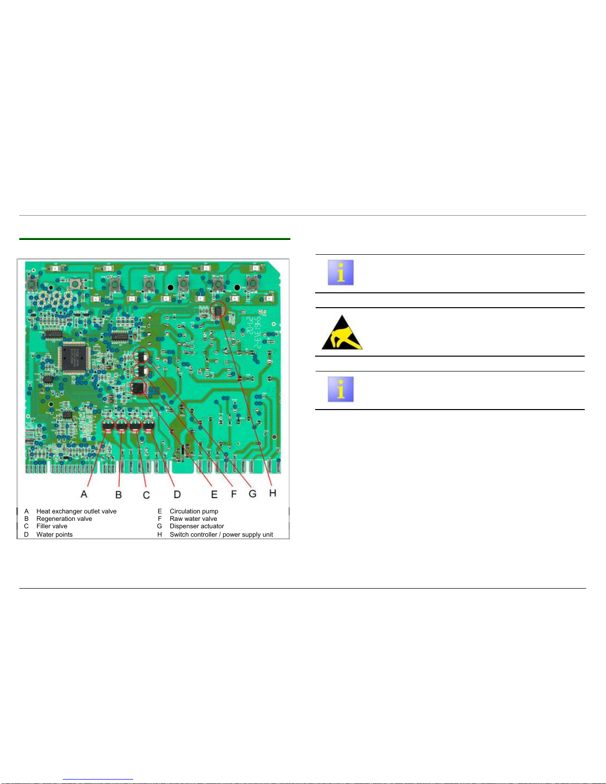
4.1.8 Listing the triacs
Before replacing a module, always start the customer
service test programme.
Before replacing a module, follow the ESD instructions.
Before replacing a module due to a defective triac,
test the actuated component.
A Heat exchanger outlet valve E Circulation pump
B Regeneration valve F Raw water valve
C Filler valve G Dispenser actuator
D Water points
H Switch controller / power supply unit
815_58300000003806_ara_en_e.doc – 30.01.12 Seite 12 von 67
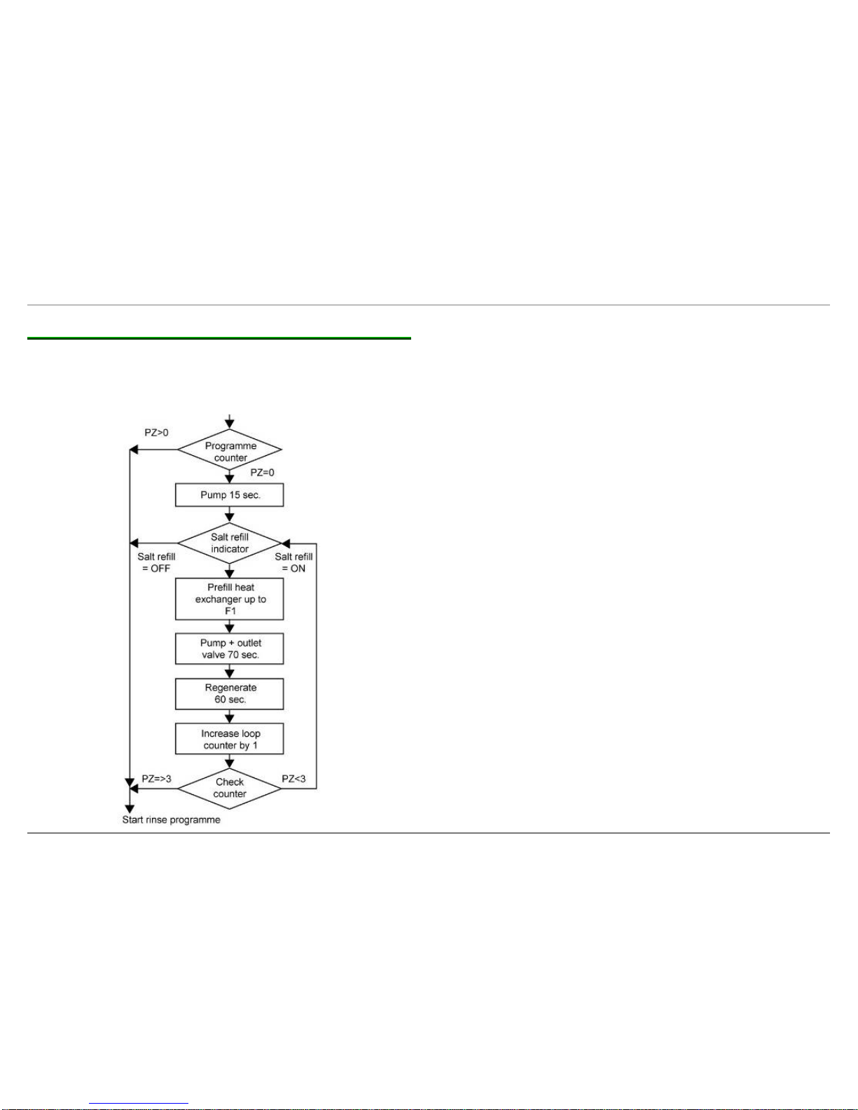
4.1.9 Initial start-up / Replacing the electronics
The following programme sequence must be taken into consideration
during the initial start-up or when replacing the electronics. (
Programme counter = 0 ! )
Programme sequence during the initial start-up with heat exchanger
815_58300000003806_ara_en_e.doc – 30.01.12 Seite 13 von 67
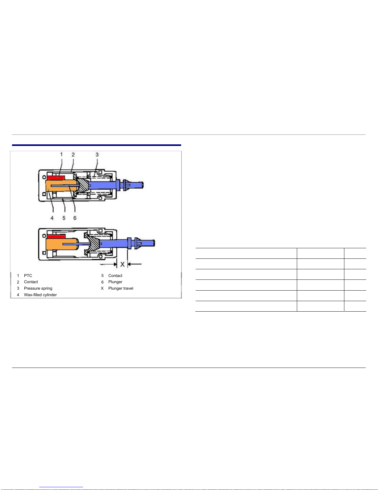
4.2 Actuator
The thermohydraulic system consists of a metal cylinder with plunger.
The cylinder is filled with a substance which expands greatly when
heated. The heat source is a PTC (positive temperature coefficient)
(1) which is in direct contact with the metal cylinder (4). A strong
pressure spring (3) returns the plunger (6) back to its original position
when the heat source is switched off.
When voltage is applied to the PTC (1), the PTC heats up and
transfers the heat to the wax-filled metal cylinder (4). The wax
expands and forces the plunger (6) out of the cylinder. The plunger (6)
transfers the mechanical movement to the release mechanism for
dispensing the detergent and rinse-aid. If the heat source is switched
off, the volume of wax is reduced by the cooling process. The
pressure spring (3) returns the plunger (6) back to its original position.
Technical specifications:
Designation Value Unit
Nominal voltage 110–240 V
Frequency 50 / 60 Hz
Resistor
0.5–1.5
kΩ
Actuation time approx. 2 min.
Reset time approx. 3 min.
1
PTC
5
Contact
2
Contact
6
Plunger
3
Pressure spring
X
Plunger travel
4
Wax-filled cylinder

815_58300000003806_ara_en_e.doc – 30.01.12 Seite 14 von 67
4.3 Aqua sensor (optional)
The infrared light-emitting diode (B) and the photodiode (A) are
located opposite each other in a U-shaped translucent housing on a
board. The infrared diode (B) transmits infrared light through the water
flowing between the U to the light-sensitive base of the photodiode
which then becomes conductive.
If the water is turbid, the light emitted by the infrared diode can no
longer reach the photodiode. The absent voltage signal is detected by
the microcomputer. Depending on the programme type, the water is
changed after the prerinse or even the washing temperature is
changed. If the turbidity value is not reached, the water remains in the
rinsing tank for the wash cycle. In each programme sequence in
which the Aqua sensor is active the sensor is also calibrated. If
a calibration cannot be implemented successfully, a permanently
stored programme is executed and an error is saved in the module.
A Photodiode C Detergent solution
B Infrared diode

815_58300000003806_ara_en_e.doc – 30.01.12 Seite 15 von 67
4.4 Aqua Stop valve
The Aqua Stop valve consists of two solenoid valves (A) in a row, the
filler and safety valves. These valves are actuated in parallel. There
are two filters on the screw connection for the tap. Under the filters
is the flow limiter.
4.4.1 Safety function
The safety function may be actuated via the safety level chamber
or via the float in the base pan.
The Aqua Stop valve is enclosed by a housing. The housing
is connected to the bottom pan by a leakage water hose (sleeve of the
inlet hose) (D). The inlet hose (C) and the electric control cable (B) for
the solenoid valve are situated in the leakage water hose (D). If leaks
occur in the area of the valve or inlet hose, these are conveyed into
the base pan via the leakage water hose.
4.4.2 Technical specifications
Designation Value Unit
Nominal voltage 230 - 240 V
Frequency 50 Hz
Resistor approx. 2
kΩ
Flow rate 2.75 l/min
Water pressure 0.5 - 10 bar
A
Solenoid valve
C
Inlet hose
B
Control cable
D
Leakage-water hose
815_58300000003806_ara_en_e.doc – 30.01.12 Seite 16 von 67
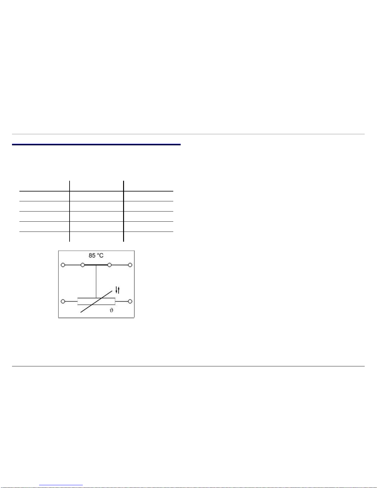
4.5 NTC
The utilised temperature safety switch (>85 °C) is combined with the
NTC sensor. If a fault occurs, the heater is switched off at a water
temperature of 85 °C (operates in switching mode).
Temperature in °C Resistance in kW Tolerance +/– °C
25 48.4 7.9
30 38.5 7.1
50 16.5 6.2
60 11.0 5.6
65 9.1 5.5
815_58300000003806_ara_en_e.doc – 30.01.12 Seite 17 von 67
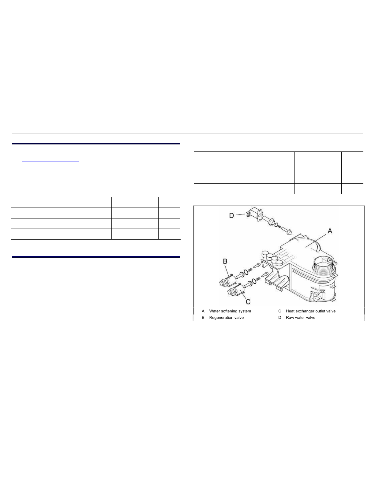
4.6 Regeneration / drainage valve
The regeneration valve (B) and the drainage valve (C) are situated in
the water softening system. If the regeneration valve (B) is actuated,
the water stored in the regeneration chamber is conveyed through the
water softening system (A). If the drainage valve (C) is actuated, the
water stored in the heat exchanger is conveyed into the rinsing tank
via the water softening system (A).
Technical specifications:
Designation Value Unit
Nominal voltage 230 - 240 V
Frequency 50 Hz
Resistance 2.45
kΩ
4.7 Raw water valve
The raw water valve (D) is located at the rear on the water softening
system (A) and is responsible for admixing hard water.
The raw or soft water valve (D) is actuated via the electronics module
which calculates how frequently and how long the valve is to be
actuated for. As a result, a constant water hardness of approx. 5° dH
is obtained. For this reason it is important to set the hardness range
precisely.
If the valve is actuated (open), the raw water is conveyed through the
water softening system and softened. If the valve is not actuated
(closed), the inlet to the water softening system is sealed and the raw
water flows directly into the heat exchanger via the water inlet.
Technical specifications:
Designation Value Unit
Nominal voltage 230 - 240 V
Frequency 50 Hz
Resistance 2.45
kΩ
A Water softening system C Heat exchanger outlet valve
B Regeneration valve D Raw water valve
815_58300000003806_ara_en_e.doc – 30.01.12 Seite 18 von 67
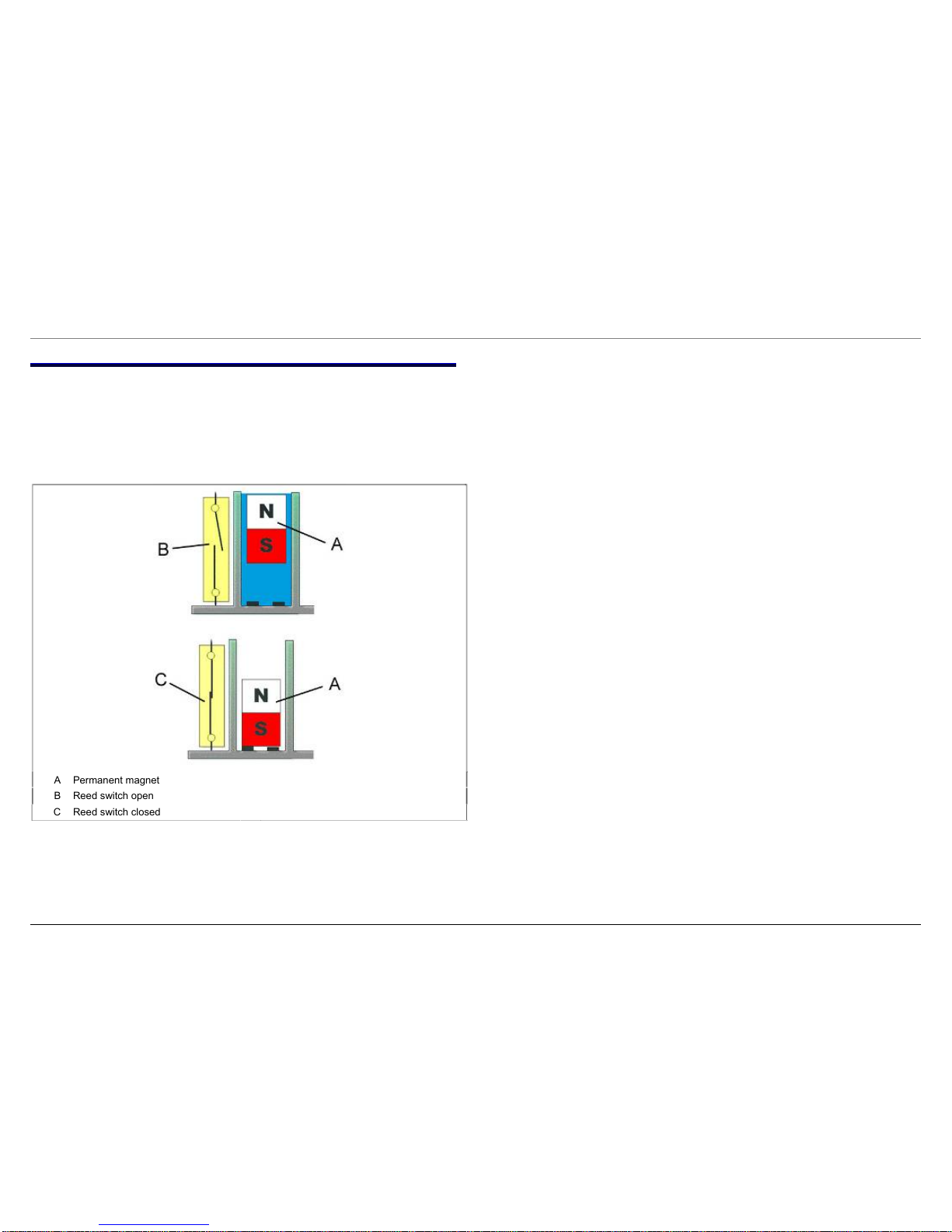
4.8 Salt and rinse-aid indicators (optional)
The dispenser contains a float with an integrated permanent magnet
(A). The magnetic field actuates a reed switch on the outside of the
dispenser. The lamps of the refill indicators in the control panel are
switched on via this reed switch.
A Permanent magnet
B Reed switch open
C Reed switch closed
815_58300000003806_ara_en_e.doc – 30.01.12 Seite 19 von 67
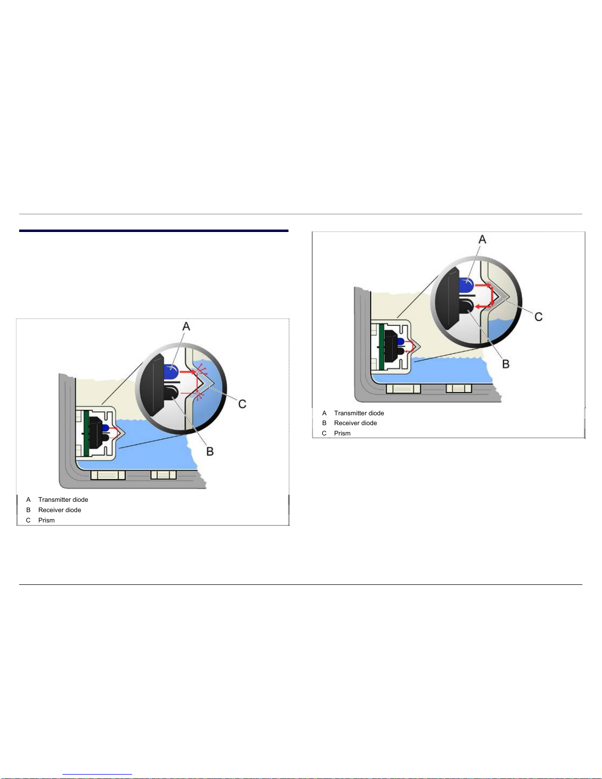
4.9 Optical low rinse-aid sensor (optional)
The optical low rinse-aid sensor consists of a transmitter diode and
a receiver diode.
A light beam is transmitted from the transmitter diode (A) to the
receiver diode (B) via a prism (C). If the dispenser is full, the light
beam in the prism is scattered. The received signal is weaker than
the transmitted one.
If the dispenser is empty, the light beam in the prism is reflected.
The received signal is the same as the transmitted signal.
The module evaluates the received signal and the refill indicator LED
is actuated.
A
Transmitter diode
B
Receiver diode
C
Prism
A
Transmitter diode
B
Receiver diode
C
Prism
815_58300000003806_ara_en_e.doc – 30.01.12 Seite 20 von 67
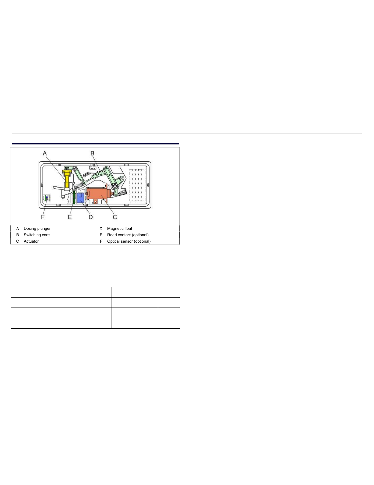
4.10 Dispenser
The release mechanism is activated by an actuator (C). When the
actuator is actuated for the first time, the detergent-dispenser cover
is opened. At the same time the release pawl engages with the
switching core (B) of the rinse-aid lever so that when the actuator (C)
is activated again, the dosing plunger (A) is lifted off the rinse aid.
Technical specifications Value Unit
Rinse aid capacity 120 ml
Setting 1–6 1 each ml
Detergent capacity max. 45 g
See Actuator for additional technical specifications.
A
Dosing plunger
D
Magnetic float
B
Switching core
E
Reed contact (optional)
C
Actuator
F
Optical sensor (optional)
815_58300000003806_ara_en_e.doc – 30.01.12 Seite 21 von 67
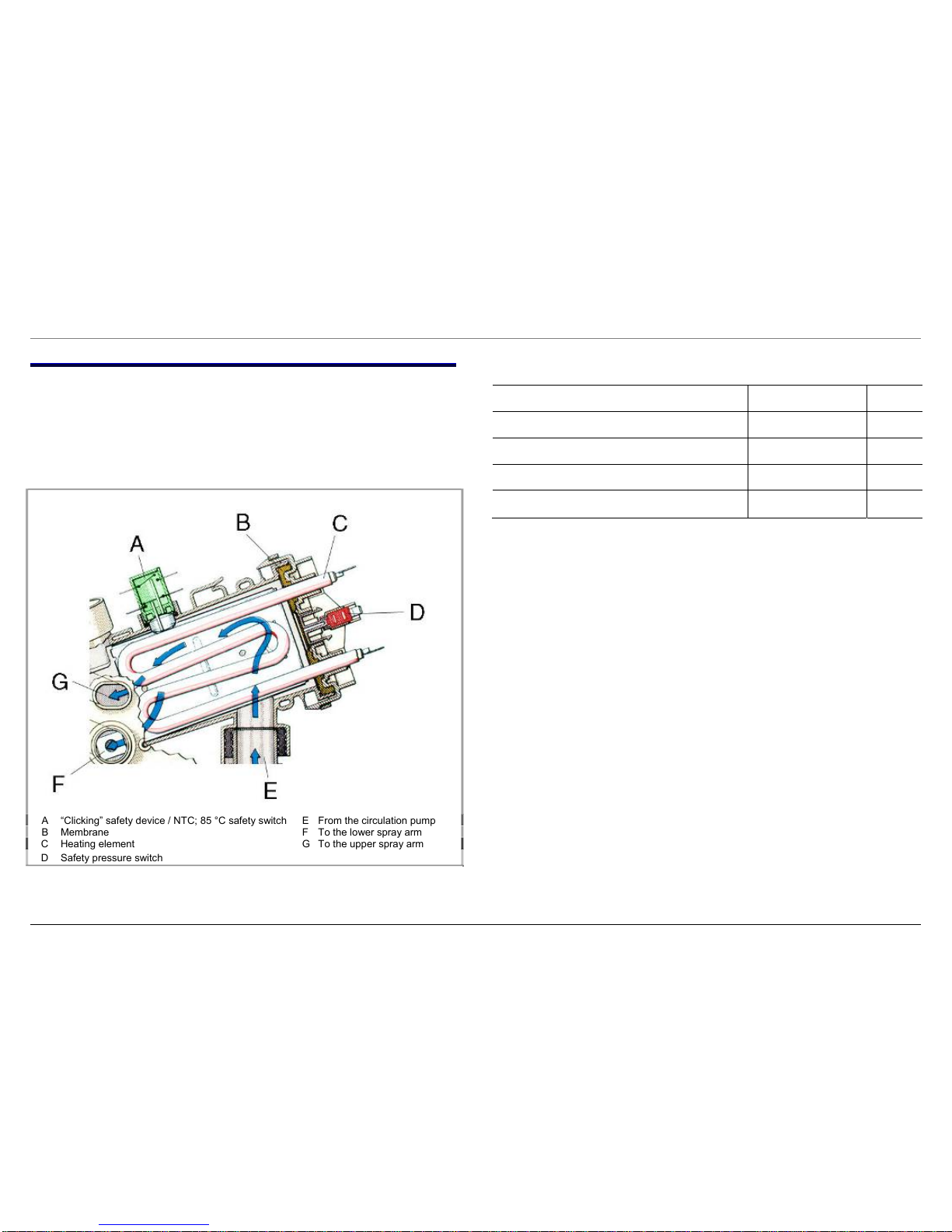
4.11 Instantaneous water heater
The instantaneous water heater is installed in the water circuit for the
spray arms. When the detergent solution flows through the instantaneous water heater, a rubber membrane (B) attached to the flange
actuates the safety pressure switch (D) for the heating element (C). If
the pressure drops, the heater switches off. The heating position is
overtravelled, preventing dry heating.
Technical specifications:
Designation Value Unit
Nominal voltage 230–240 V
Frequency 50 Hz
Power 2150 W
Resistor approx. 22
Ω
A “Clicking” safety device / NTC; 85 °C safety switch E From the circulation pump
B Membrane F To the lower spray arm
C Heating element G To the upper spray arm
D Safety pressure switch
 Loading...