

Siemens SCALANCE XR-300M Operating Instructions Manual
SCALANCE XR-300M
___________________
___________________
___________________
___________________
___________________
___________________
___________________
___________________
___________________
SIMATIC NET
Industrial Ethernet switches
SCALANCE XR-300M
Compact Operating Instructions
05/2016
A5E02661171
Introduction
1
Safety notes
2
Description
3
Assembling
4
Connecting
5
Technical data
6
Dimension drawings
7
Approvals
8
Appendix
A
-11
Siemens AG
Division Process Industries and Drives
Postfach 48 48
90026 NÜRNBERG
GERMANY
A5E02661171-11
Ⓟ
Copyright © Siemens AG 2010 - 2016.
All rights reserved
Legal information
Warning notice system
DANGER
indicates that death or severe personal injury will result if proper precautions are not taken.
WARNING
indicates that death or severe personal injury may result if proper precautions are not taken.
CAUTION
indicates that minor personal injury can result if proper precautions are not taken.
NOTICE
indicates that property damage can result if proper precautions are not taken.
Qualified Personnel
personnel qualified
Proper use of Siemens products
WARNING
Siemens products may only be used for the applications described in the catalog and in the relevant technical
re required to ensure that the products operate safely and without any problems. The permissible
ambient conditions must be complied with. The information in the relevant documentation must be observed.
Trademarks
Disclaimer of Liability
This manual contains notices you have to observe in order to ensure your personal safety, as well as to prevent
damage to property. The notices referring to your personal safety are highlighted in the manual by a safety alert
symbol, notices referring only to property damage have no safety alert symbol. These notices shown below are
graded according to the degree of danger.
If more than one degree of danger is present, the warning notice representing the highest degree of danger will
be used. A notice warning of injury to persons with a safety alert symbol may also include a warning relating to
property damage.
The product/system described in this documentation may be operated only by
task in accordance with the relevant documentation, in particular its warning notices and safety instructions.
Qualified personnel are those who, based on their training and experience, are capable of identifying risks and
avoiding potential hazards when working with these products/systems.
Note the following:
documentation. If products and components from other manufacturers are used, these must be recommended
or approved by Siemens. Proper transport, storage, installation, assembly, commissioning, operation and
maintenance a
All names identified by ® are registered trademarks of Siemens AG. The remaining trademarks in this publication
may be trademarks whose use by third parties for their own purposes could violate the rights of the owner.
We have reviewed the contents of this publication to ensure consistency with the hardware and software
described. Since variance cannot be precluded entirely, we cannot guarantee full consistency. However, the
information in this publication is reviewed regularly and any necessary corrections are included in subsequent
editions.
for the specific
04/2016 Subject to change

Table of contents
1 Introduction ............................................................................................................................................. 5
2 Safety notes ............................................................................................................................................ 9
3 Description ............................................................................................................................................ 15
4 Assembling ........................................................................................................................................... 25
5 Connecting ........................................................................................................................................... 39
1.1 Introduction to the XR-300M ..................................................................................................... 5
1.2 Product group XR-300M ........................................................................................................... 6
1.3 Type designations ..................................................................................................................... 7
2.1 Use of approved components ................................................................................................... 9
2.2 Important notes on using the SCALANCE X-300 product family ........................................... 10
2.3 Important notes on using the device in hazardous areas ....................................................... 12
2.4 Notes on the power supply 100 to 240 V AC .......................................................................... 12
2.5 PELV ....................................................................................................................................... 13
3.1 Unpacking and checking ......................................................................................................... 15
3.2 Components of the XR-300M product .................................................................................... 15
3.3 Product group XR-300M ......................................................................................................... 16
3.3.1 SCALANCE XR324-12M ........................................................................................................ 16
3.4 The SET / SELECT button ...................................................................................................... 18
3.5 LED display ............................................................................................................................. 19
3.6 C-PLUG .................................................................................................................................. 23
3.6.1 Area of application and function of the C-PLUG ..................................................................... 23
3.6.2 Removal and insertion of the C-PLUG (rack devices) ............................................................ 24
4.1 Safety notices for installation .................................................................................................. 25
4.2 Suitable installation location at temperatures above 50 °C .................................................... 25
4.3 Suitable cables for temperatures above 70 °C - cable 50 °C - 70 °C (ATEX) ........................ 26
4.4 Suitable cables for temperatures in excess of 70 °C (ATEX) ................................................. 26
4.5 Installation ............................................................................................................................... 26
4.6 19" rack mounting ................................................................................................................... 27
4.7 Installation of modular devices ............................................................................................... 32
4.7.1 Installation and removal of media modules ............................................................................ 32
4.7.2 SFP installation in SFP media module ................................................................................... 36
5.1 Safety when connecting up ..................................................................................................... 39
5.2 Notes on commissioning ......................................................................................................... 41
SCALANCE XR-300M
Compact Operating Instructions, 05/2016, A5E02661171-11
3

Table of contents
6 Technical data ...................................................................................................................................... 51
7 Dimension drawings .............................................................................................................................. 59
8 Approvals ............................................................................................................................................. 63
A Appendix .............................................................................................................................................. 71
Index .................................................................................................................................................... 73
5.3 Functional ground .................................................................................................................. 41
5.3.1 Connecting functional ground ................................................................................................ 41
5.4 Signaling contact .................................................................................................................... 42
5.4.1 Signaling contact .................................................................................................................... 42
5.4.2 24 V DC signaling contact ...................................................................................................... 43
5.5 Diagnostics port ..................................................................................................................... 44
5.5.1 Diagnostics port rear .............................................................................................................. 44
5.6 Power supply .......................................................................................................................... 45
5.6.1 Connecting devices with 24 VDC power supply .................................................................... 45
5.6.1.1 Connecting the external 24 VDC power supply ..................................................................... 45
5.6.1.2 XR-300M device variants with 24 V DC power supply .......................................................... 47
5.6.2 Connecting devices with 100 to 240 VAC power supply ....................................................... 47
5.6.2.1 XR-300M device variants with 100 to 240 VAC power supply .............................................. 47
5.6.2.2 Notes on the power supply 100 to 240 V AC ......................................................................... 47
5.6.2.3 Fitting the connector for 100 to 240 V AC .............................................................................. 48
5.6.2.4 Connecting the 100 to 240 V AC power supply ..................................................................... 50
6.1 Construction, installation and environmental conditions ........................................................ 51
6.2 Connectors and electrical data .............................................................................................. 53
6.3 Cable lengths ......................................................................................................................... 54
6.4 Block architecture................................................................................................................... 55
6.5 Other properties ..................................................................................................................... 56
7.1 XR-300M dimension drawings ............................................................................................... 59
8.1 XR-300M approvals, certificates ............................................................................................ 63
8.2 SCALANCE X-300 declaration of conformity ......................................................................... 67
8.3 XR-300M FDA and IEC approvals ......................................................................................... 68
8.4 Overview of XR-300M approvals ........................................................................................... 68
8.5 XR-300M mechanical stability (in operation) ......................................................................... 69
A.1 The connector system M12/X coded according to IEC 61076-2-109 .................................... 71
SCALANCE XR-300M
4 Compact Operating Instructions, 05/2016, A5E02661171-11
1
1.1
Introduction to the XR-300M
Purpose of the Operating Instructions (compact)
Validity of these Operating Instructions (compact)
XR-300M
Names of the devices in these operating instructions (compact)
Classification
Description
Terms used
X-300 product line, the term IE switches X-300 is used.
IE switches X-300
used.
XR-300M
Device
For a device, only the device name is used.
XR324-12M
XR324-12M
front)
device
XR324-12M
(all)
Where can I find more detailed information on the product?
These operating instructions (compact) contain information with which you will be able to
install and connect up a device of the SCALANCE X-300 product line.
These Operating Instructions (compact) are valid for the product group
SCALANCE X-300 product line (see product overview).
Product line For all devices and variants of all product groups within the SCALANCE
Product group For all devices and variants of a product group, only the product group is
Variant For a variant of the device, the device name has the appropriate variant
added to it in brackets (2x24V).
All variants of a
For all variants of the device, the device name has (all) added to it.
A CD is supplied with the IE Switches X-300 on which you will find a detailed description of
the products in PDF format in the relevant subfolder.
(2 x 24 V DC, cable outlet
of the
SCALANCE XR-300M
Compact Operating Instructions, 05/2016, A5E02661171-11
5
Introduction
Security messages
Note
Siemens offers IT security mechanisms for its aut
to support the safe operation of the plant/machine. Our products are also continuously
developed further with regard to IT security. We therefore recommend that you regularly
check for updates of our products an
information in:
(
en
Here, you can register for a product
For the safe operation of a plant/machine, however, it is also necessary to integrate the
automation components into an overall IT security concept for the entire plant/machine,
w
Products from other manufacturers that are being used mu
SIMATIC NET glossary
1.2
Product group XR-300M
Device
Properties
Order number
XR324-12M
Diagnostics port at rear
XR324-12M
Diagnostics port at rear
1.2 Product group XR-300M
omation and drive product portfolio in order
d that you only use the latest versions. You will find
http://support.automation.siemens.com/WW/llisapi.dll?func=cslib.csinfo2&aktprim=99&lang=
)
-specific newsletter.
hich corresponds to the state-of-the-art IT technology. You will find information on this in:
(http://www.siemens.com/industrialsecurity)
st also be taken into account.
Explanations of many of the specialist terms used in this documentation can be found in the
SIMATIC NET glossary.
You will find the SIMATIC NET glossary here:
● SIMATIC NET Manual Collection or product DVD
The DVD ships with certain SIMATIC NET products.
● On the Internet under the following address:
50305045 (http://support.automation.siemens.com/WW/view/en/50305045
2 x 24 VDC
LEDs, connector power supply and data cable outlet on
front
1 x 100 to 240 VAC
LEDs, connector power supply and data cable outlet on
front
)
6GK5 324-0GG00-1AR2
6GK5 324-0GG00-3AR2
SCALANCE XR-300M
6 Compact Operating Instructions, 05/2016, A5E02661171-11
Introduction
Device
Properties
Order number
XR324-12M
connector power supply and data cable outlet at rear
XR324-12M
XR324-12M TS
Diagnostics port at rear
1.3
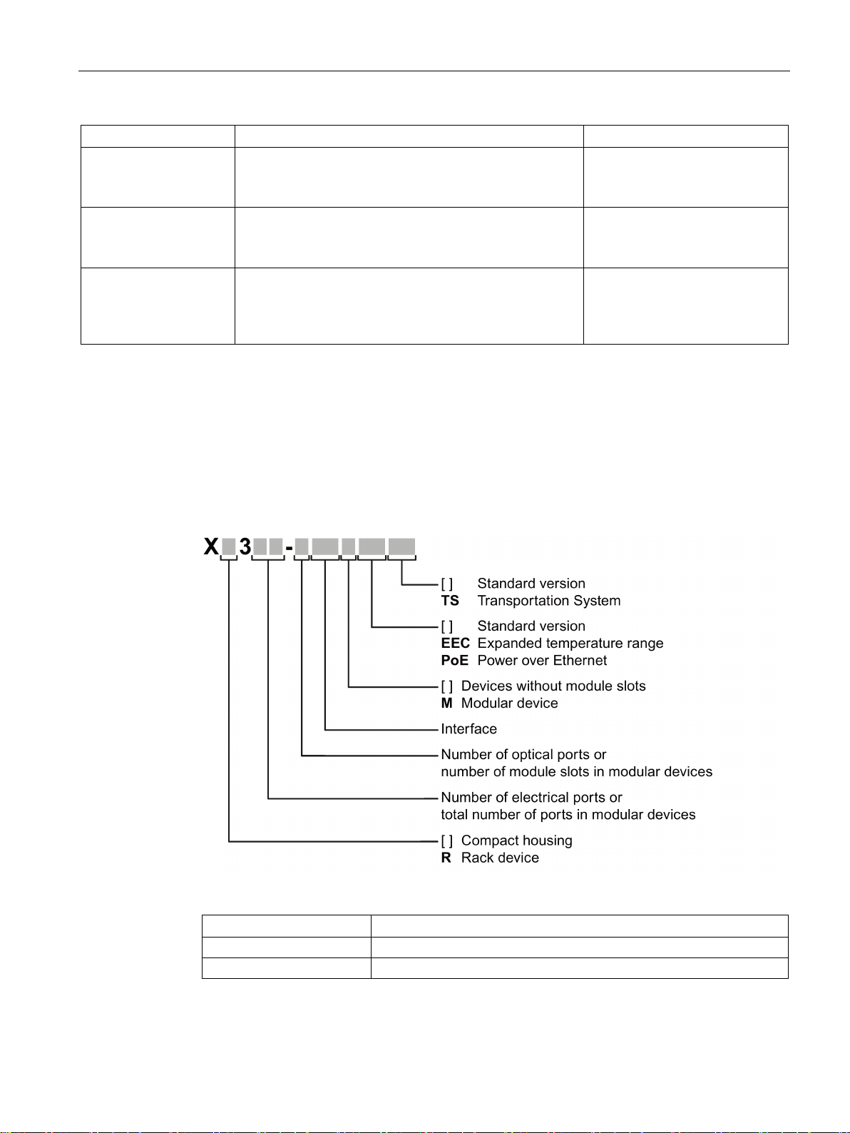
Type designations
Structure of the type designation
Interface
Property
FE
Electrical RJ-45 port for 10/100 Mbps.
[-]
Electrical RJ-45 port for 10/100 Mbps or 10/100/1000 Mbps.
1.3 Type designations
2 x 24 VDC
LEDs and diagnostics port on front
1 x 100 to 240 VAC
LEDs and diagnostics port on front
connector power supply and data cable outlet at rear
2 x 24 VDC, modules varnished
LEDs, connector power supply and data cable outlet on
front
The type designation of an IE Switch X-300 is made up of several parts that have the
following meaning:
6GK5 324-0GG00-1HR2
6GK5 324-0GG00-3HR2
6GK5 324-0GG00-1CR2
Interfaces of devices without optical ports:
SCALANCE XR-300M
Compact Operating Instructions, 05/2016, A5E02661171-11
7
Introduction
Interface
Property
FE
SC port 100 Mbps multimode FO cable (up to max. 5 km).
[-]
SC port 1000 Mbps multimode FO cable (up to max. 750 m).
LD
SC port 1000 Mbps single mode FO cable (up to max. 10 km).
LH
SC port 1000 Mbps single mode FO cable (up to max. 40 km).
LH+
SC port 1000 Mbps single mode FO cable (up to max. 70 km).
Note
SCALANCE X320-3LD FE
The SCALANCE X320
for multimode fiber
single mode fiber
•
•
•
1.3 Type designations
Interfaces of devices with optical ports:
LD FE SC port 100 Mbps single mode FO cable (up to max. 26 km).
If information applies to all devices, the term "IE Switches X-300" is used. If information
applies to only a particular product group, the relevant names will be used without extra
information on the type or number of interfaces. Examples: "X-300" stands for non-modular
devices with a compact housing, "XR-300" means all rack devices, "X-300M" means all
modular devices etc.
-3LD FE deviates from the type designation in that it has an SC port
-optic cable up to a maximum of 5 km in length and two SC ports for
-optic cable up to a maximum of 26 km in length.
Port 21: Multimode
Port 22: LD (long distance, single mode)
Port 23: LD (long distance, single mode)
SCALANCE XR-300M
8 Compact Operating Instructions, 05/2016, A5E02661171-11
2
Read the safety notices
2.1
Use of approved components
WARNING
Use of approved components
Safety notices on use in hazardous areas
General safety notices relating to protection against explosion
WARNING
EXPLOSION HAZARD
Safety notices when using the device according to Hazardous Locations (HazLoc)
Note the following safety notices. These relate to the entire working life of the device.
You should also read the safety notices relating to handling in the individual sections,
particularly in the sections "Installation" and "Connecting up".
• Use only approved components, for example supporting brackets, SFPs, 19 inch racks.
• Create any supports you require according the dimension drawing.
DO NOT OPEN WHEN ENERGIZED.
If you use the device under HazLoc conditions you must also keep to the following safety
notices in addition to the general safety notices for protection against explosion:
This equipment is suitable for use in Class I, Division 2, Groups A, B, C and D or nonhazardous locations only.
This equipment is suitable for use in Class I, Zone 2, Group IIC or non-hazardous locations
only.
SCALANCE XR-300M
Compact Operating Instructions, 05/2016, A5E02661171-11
9
Safety notes
2.2
Important notes on using the SCALANCE X-300 product family
Safety notices on the use of the device
General information
WARNING
Safety extra low voltage
WARNING
Opening the device
General notices about use in hazardous areas
WARNING
Risk of explosion when connecting or disconnecting the device
2.2 Important notes on using the SCALANCE X-300 product family
The following safety notices must be adhered to when setting up and operating the device
and during all associated work such as installation, connecting up, replacing or opening the
device.
The equipment is designed for operation with Safety Extra-Low Voltage (SELV) by a
Limited Power Source (LPS). (This does not apply to 100 V...240 V devices.)
This means that only SELV / LPS (Limited Power Source) complying with IEC 60950-1 / EN
60950-1 / VDE 0805-1 must be connected to the power supply terminals. The power supply
unit for the equipment power supply must comply with NEC Class 2, as described by the
National Electrical Code (r) (ANSI / NFPA 70).
If the equipment is connected to a redundant power supply (two separate power supplies),
both must meet these requirements.
A power source that supplies safety extra low voltage combined with a following NEC Class
2 power limiter also meets the requirements according to IEC 60950-1 / EN 60950-1 / VDE
0805-1 or NEC Class 2. A suitable power limiter is for example the redundancy module
SITOP PSE202U NEC Class 2 (article number 6EP1962-2BA00).
DO NOT OPEN WHEN ENERGIZED.
EXPLOSION HAZARD
DO NOT CONNECT OR DISCONNECT EQUIPMENT WHEN A FLAMMABLE OR
COMBUSTIBLE ATMOSPHERE IS PRESENT.
SCALANCE XR-300M
10 Compact Operating Instructions, 05/2016, A5E02661171-11
Safety notes
WARNING
Replacing components
WARNING
Requirements for the cabinet/enclosure
Safety notices on use in hazardous areas according to ATEX and IECEx
WARNING
Requirements for the cabinet/enclosure
WARNING
Suitable cables for temperatures in excess of 70 °C
WARNING
Protection against transient voltage surges
2.2 Important notes on using the SCALANCE X-300 product family
EXPLOSION HAZARD
SUBSTITUTION OF COMPONENTS MAY IMPAIR SUITABILITY FOR CLASS I, DIVISION
2 OR ZONE 2.
When used in hazardous environments corresponding to Class I, Division 2 or Class I,
Zone 2, the device must be installed in a cabinet or a suitable enclosure.
To comply with EC Directive 94/9 (ATEX95) or the conditions of IECEx, this enclosure must
meet the requirements of at least IP54 in compliance with EN 60529.
If the cable or conduit entry point exceeds 70 °C or the branching point of conductors
exceeds 80 °C, special precautions must be taken. If the equipment is operated in an air
ambient in excess of 50 °C - 70 °C, only use cables with admitted maximum operating
temperature of at least 80 °C.
Provisions shall be made to prevent the rated voltage from being exceeded by transient
voltage surges of more than 40%. This criterion is fulfilled, if supplies are derived from
SELV (Safety Extra-Low Voltage) only.
SCALANCE XR-300M
Compact Operating Instructions, 05/2016, A5E02661171-11
11
Safety notes
2.3
Important notes on using the device in hazardous areas
WARNING
WARNING - EXPLOSION HAZARD -
WARNING
Restricted area of application
WARNING
Restricted area of application
2.4
Notes on the power supply 100 to 240 V AC
WARNING
Danger from line voltage
WARNING
Devices with a 100 to 240 VAC power supply do not have an ATEX approval.
2.3 Important notes on using the device in hazardous areas
DO NOT DISCONNECT WHILE CIRCUIT IS LIVE UNLESS AREA IS KNOWN TO BE
NON-HAZARDOUS.
This equipment is suitable for use in Class I, Division 2, Groups A, B, C and D or nonhazardous locations only.
This equipment is suitable for use in Class I, Zone 2, Group IIC or non-hazardous locations
only.
Devices with this mark have a 100 to 240 VAC power supply.
This product can only function correctly and safely if it is transported, stored, set up, and
installed correctly, and operated and maintained as recommended.
Connecting and disconnecting may only be performed by an electrical specialist.
Connect or disconnect power supply cables only when the power is turned off.
Devices with a 100 to 240 V AC power supply are not approved for use in hazardous areas
according to EC-RL-94/9 (ATEX).
SCALANCE XR-300M
12 Compact Operating Instructions, 05/2016, A5E02661171-11
Safety notes
NOTICE
No desktop operation of devices with 100 to 240 VAC power supply
NOTICE
Securing cables with dangerous voltage
NOTICE
Between the power feed-in of the device and the power supply, there must be double fuse
(phase and neutral conductor).
2.5
PELV
Note
Safety extra-low voltage
The supply of the devices by PELV (Protective Extra Low Voltage) according to DIN VDE
0100
exceed the voltage limits 25 VAC or 60 VDC.
2.5 PELV
Devices with power supply 100 to 240 VAC may only be operated if they are installed in a
19" rack. Desktop operation is not permitted!
Make sure that the connector cannot be released accidentally by pulling on the connecting
cable. Lay the cables in cable ducts or cable channels and secure the cables, where
necessary, with cable ties.
The fuses must meet the following requirements:
In areas where NEC or CEC applies:
• Suitable for AC (at least 250 V / maximum 10 A)
• Breaking current at least 10 kA
• UL/CSA listed (UL 248-1 / CSA 22.2 No.
• Category R, J, T or CC (slow-blow fuse)
Otherwise:
• Suitable for AC (at least 250 V / maximum 10 A)
• Breaking current at least 10 kA
• Approved in compliance with IEC 60127-1 / EN 60127-1
• Breaking characteristics: B or C for circuit breaker or slow-blow fuse.
-410 or IEC 60364-4-41 is permitted when the generated nominal voltage does not
SCALANCE XR-300M
Compact Operating Instructions, 05/2016, A5E02661171-11
13

Safety notes
2.5 PELV
SCALANCE XR-300M
14 Compact Operating Instructions, 05/2016, A5E02661171-11
3
3.1
Unpacking and checking
Unpacking, checking
WARNING
Do not use any parts that show evidence of damage
3.2
Components of the XR-300M product
Note
When shi
Note
Labels to identify the installed MM900 media modules are supplied with the modular devices
(M).
If you use damaged parts, there is no guarantee that the device will function according to
the specification.
If you use damaged parts, this can lead to the following problems:
• Injury to persons
• Loss of the approvals
• Violation of the EMC regulations
Use only undamaged parts.
1. Make sure that the package is complete.
2. Check all the parts for transport damage.
pped, the slots for the media modules have dummy covers fitted.
The following parts ship with a SCALANCE XR-300M:
● Device with C-PLUG exchangeable medium.
SCALANCE XR-300M
Compact Operating Instructions, 05/2016, A5E02661171-11
● 2 mounting brackets and 8 screws (M3x5 recessed head, drive: Torx) for 19" rack
installation.
● A two-pin terminal block for the signaling contact.
15
Description
3.3
Product group XR-300M
3.3.1
SCALANCE XR324-12M
Possible attachments
0 fixed ports on the base device
24 modular ports via module slots:
Note
When shipped, the slots for the media modules have a dummy cover fitted.
3.3 Product group XR-300M
● Connecting cable for the diagnostics port.
● Adhesive feet for desktop operation.
● Product CD with documentation and software.
For devices with a 100 to 240 VAC power supply also:
● A two-pin connector for the power supply.
For devices with a 24 VDC power supply, also:
● A four-pin terminal block for the power supply.
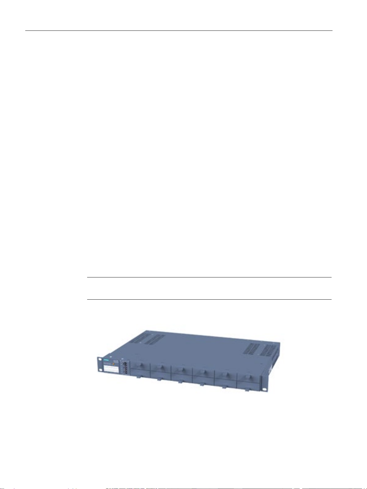
The SCALANCE XR324-12M is a fully modular device and has 24 ports.
●
●
12 media modules (optical or electrical as required) can be combined using slots (S1S12) depending on the application. End devices and other network segments are
connected according to the modules being used.
Image 3-1 SCALANCE XR324-12M with blind covers
SCALANCE XR-300M
16 Compact Operating Instructions, 05/2016, A5E02661171-11
Description
Overview of the SCALANCE XR324-12M product
Device
Variant
Order number
XR324-12M
Diagnostics port at rear
XR324-12M
Diagnostics port at rear
XR324-12M
connector power supply and data cable outlet at rear
XR324-12M
connector power supply and data cable outlet at rear
XR324-12M TS
Diagnostics port at rear
Example of a configuration
CAUTION
Use only approved media modules in the module slots
3.3 Product group XR-300M
2 x 24 VDC
LEDs, connector power supply and data cable outlet on
front
1 x 100 to 240 VAC
LEDs, connector power supply and data cable outlet on
front
2 x 24 VDC
LEDs and diagnostics port on front
1 x 100 to 240 VAC,
LEDs and diagnostics port on front
2 x 24 VDC, modules varnished
LEDs, connector power supply and data cable outlet on
front
6GK5 324-0GG00-1AR2
6GK5 324-0GG00-3AR2
6GK5 324-0GG00-1HR2
6GK5 324-0GG00-3HR2
6GK5 324-0GG00-1CR2
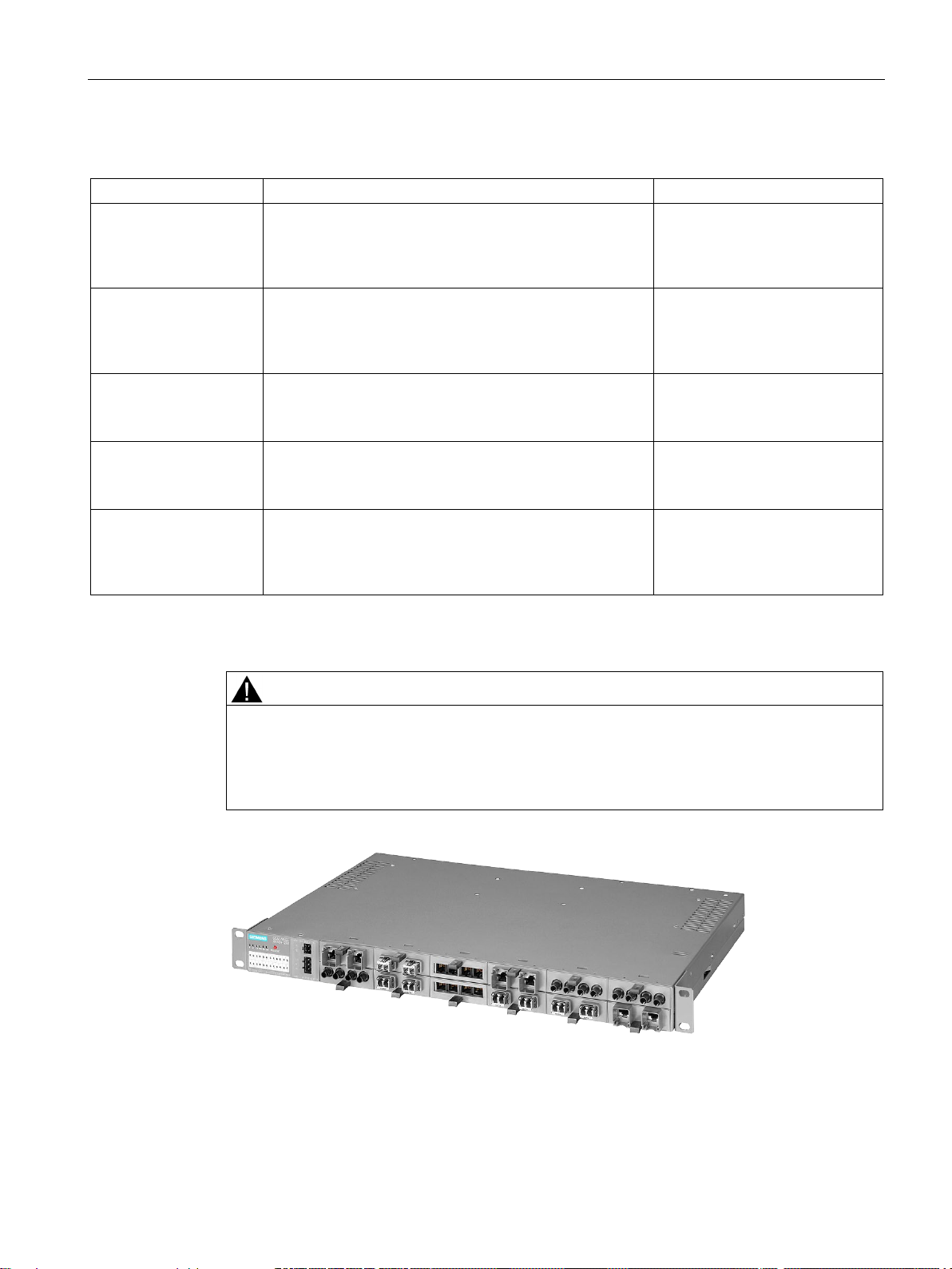
The connection of end devices or other network segments does not depend on the module
slot, but rather on the selected media module.
Refer to the section Media module installation in slot.
Image 3-2 SCALANCE XR324-12M with MM900
SCALANCE XR-300M
Compact Operating Instructions, 05/2016, A5E02661171-11
17
Description
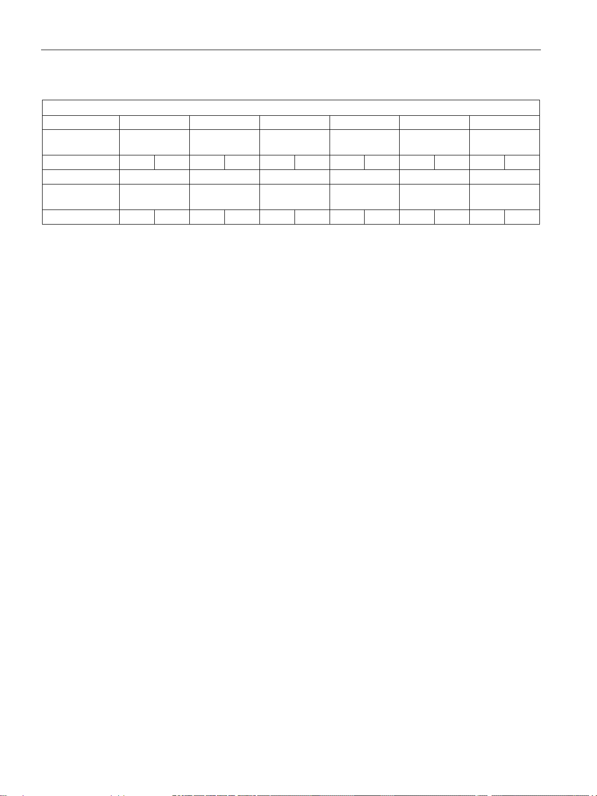
Slot number
S1
S2
S3
S4
S5
S6
Media
modules used
Port number
P1
P2
P1
P2
P1
P2
P1
P2
P1
P2
P1
P2
Slot number
Media
modules used
Port number
P1
P2
P1
P2
P1
P2
P1
P2
P1
P2
P1
P2
3.4
The SET / SELECT button
Change the display mode
Resetting the device to the factory defaults
Definition of the fault mask
3.4 The SET / SELECT button
MM992-2CUC MM992-2CUC MM992-2CUC MM991-2 (SC) MM991-2 (SC) MM991-2 (SC)
S7 S8 S9 S10 S11 S12
MM992-2CUC MM992-2CUC MM992-2CUC MM991-2 MM991-2 MM991-2
The SET/SELECT button is located on the top of the housing of devices of the X-300 EEC
series. On all other devices, this button is on the front panel of the housing beside the LED
display. The SET/SELECT button has several functions that are described below.
By pressing the button briefly, you change to the display mode of the LED display. For more
detailed information on this topic, refer to the section "LED display".
If you reset, all the changes you have made will be overwritten by factory defaults. Follow the
steps outlined below:
1. Turn on display mode A. Display mode A is active when the "DM" LED is not lit. If this
LED is lit or flashing, you will need to press the SET/SELECT briefly (possibly several
times) until the "DM" LED goes off. If the SELECT/SET button is not pressed for longer
than a minute, the device also turns on display mode A.
2. Hold down the SELECT/SET button for 12 seconds. If you release the button before the
12 seconds have elapsed, the reset is canceled.
Using the fault mask, you specify an individual "good status" for the connected ports and the
power supply. Deviations from this status are then displayed as errors/faults.
1. Turn on display mode A or D. Display mode A is active when the "DM" LED is not lit.
Display mode D is active when the "DM" LED flashes yellow/orange. If a different display
mode is active, you will need to press the SET/SELECT briefly (possibly several times)
until the required display mode is active.
SCALANCE XR-300M
18 Compact Operating Instructions, 05/2016, A5E02661171-11
2. Hold down the SET/SELECT button for five seconds. After three seconds, the "DM" LED
begins to flash. If you release the button before the five seconds have elapsed, the
previous fault mask will be retained.
Description
Enable/disable the redundancy manager
3.5
LED display
The "RM" LED for the "redundancy manager" function
LED color
LED status
Meaning
-
off
The device is not operating in the role of "redundancy manager".
ring is working without problems, monitoring is activated.
switched through.
The "SB" LED for the standby function
LED color
LED status
Meaning
-
off
The standby function is disabled.
green
on
The standby function is enabled. The standby section is passive.
green
flashes
The standby function is enabled. The standby section is active.
3.5 LED display
1. Turn on display mode B. Display mode B is active when the "DM" LED is lit green. If a
different display mode is active, you will need to press the SET/SELECT briefly (possibly
several times) until display mode B is active.
2. Hold down the SET/SELECT button for five seconds. After three seconds, the "DM" LED
begins to flash. If you release the button before the five seconds have elapsed, the action
is aborted.
3. The result of the action depends on the initial situation:
– If the redundancy manager and media redundancy were disabled, media redundancy
is also enabled after enabling the redundancy manager.
– If you disable the redundancy manager, media redundancy remains enabled.
The "RM" LED indicates whether or not the device is operating in the role of redundancy
manager and whether or not the ring is operating error-free.
green on The device is operating in the role of redundancy manager. The
green flashes The device is operating in the role of redundancy manager. An
interruption has been detected on the ring and the device has
This LED shows the status of the standby function.
SCALANCE XR-300M
Compact Operating Instructions, 05/2016, A5E02661171-11
19
Description
The "F" LED for the fault status
LED color
LED status
Meaning during the device startup
-
off
Device startup completed successfully.
red
flashes
Bad firmware image.
LED color
LED status
Meaning during operation
red
on
The device has detected an error. The signaling contact opens.
The "DM" LED for the display mode
LED color
LED status
Meaning
-
off
Display mode A
green
on
Display mode B
orange
on
Display mode C
yellow/orange
flashes
Display mode D
Selecting the display mode
Pressing the SELECT/SET button
starting at display mode A
Status of the "DM" LED
Display mode
-
off
Display mode A (default mode)
Press once
lit green
Display mode B
Press twice
lit orange
Display mode C
Press 3 times
flashes yellow/orange
Display mode D
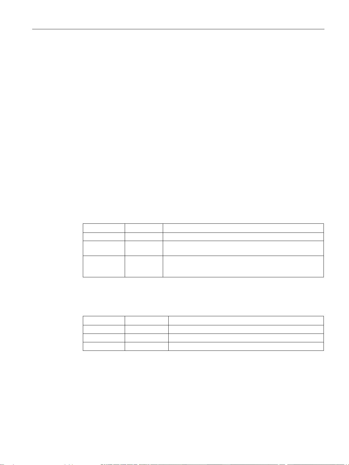
The "L1" and "L2" or "L" LEDs for the power supply
3.5 LED display
The "F" LED (fault) provides information on the error/fault status of the device. While the
device is starting up, this LED has the following meaning:
red on Device startup not yet completed or a fault/error has occurred.
During normal operation, the "F" LED provides the following information:
- off No operating problems.
The "DM" LED (Display Mode) indicates which of the four display modes A, B, C or D is
currently active. The meaning of the L1, L2 and P1, P2, ... LEDs depends on the display
mode.
Press the SELECT/SET button to set the required display mode. If the SELECT/SET button
is not pressed for longer than a minute, the device automatically changes to display mode A.
Whereas on other devices, the "L1" and "L2" LEDs indicate information about the power, on
the SCALANCE X306-1LD FE, this is done by the "L" LED. A redundant power supply for
this device can be recognized by the color of the LED.
SCALANCE XR-300M
20 Compact Operating Instructions, 05/2016, A5E02661171-11
Description
Meaning in display mode A, B or C
LED
Color
Status
Meaning
_
off
Power supply L1 / L2 lower than 17 V *)
-
off
Power supplies L1 and L2 less than 17 V or not connected.
(redundant supply).
Meaning in display mode D
LED
Color
Status
Meaning
17 V *), the signaling contact does not respond.
V *), the signaling contact responds.
falls below 17 V, the signaling contact does not respond.
17 V, the signaling contact responds.
below 17 V, the signaling contact responds.
Note
Devices of the X-300EEC product group
When using only one power supply unit 24
"L1" and "L2" signal the existence of the power supply L1 and L2.
When using two 24
the primary volt
supply is intact, a fault occurring on a power supply unit on the secondary side can be
recognized.
3.5 LED display
L1 / L2
green on Power supply L1 / L2 higher than 17 V *)
L
orange on Power supply L1 or L2 higher than 17 V
green on Power supplies L1 and L2 higher than 17 V
*)) The following applies to the X-300EEC:
• For devices with power supply unit 24 to 48 VDC: Limit voltage = 17 VDC
• For devices with a multiple range power supply unit 100 to 240 VAC / 60 to 250 VDC:
Limit voltage = 46.5 VDC or 80 VAC
L1 / L2 _ off Power supply L1 / L2 is not monitored. If L1 / L2 falls below
green on Power supply L1 / L2 is monitored. If L1 / L2 falls below 17
(no redundant supply).
L - off Power supplies L1 and L2 are not monitored. If L1 or L2
orange on Power supply L1 or L2 is monitored. If L1 or L2 falls below
green on Power supplies L1 and L2 are monitored. If L1 and L2 fall
*)) The following applies to the X-300EEC:
• For devices with power supply unit 24 to 48 VDC: Limit voltage = 17 VDC
• For devices with a multiple range power supply unit 100 to 240 VAC / 60 to 250 VDC:
Limit voltage = 46.5 VDC or 80 VAC
VDC and two 24 VDC power supplies, the LEDs
VDC power supply units, the LEDs "L1" and "L2" signal the existence of
age and the secondary voltage for both power supply units. If the power
SCALANCE XR-300M
Compact Operating Instructions, 05/2016, A5E02661171-11
21
Description
The P1, P2, ... LEDs for the port status
Meaning in display mode A
LED color
LED status
Meaning
cable not connected).
Link exists and port in "blocking" status. In this status, the
data).
ond
status, no data is sent or received via the port.
ond
tus, the data traffic of another port is mirrored to this port.
sending of data is indicated for the optical gigabit ports.
Meaning in display mode B
LED color
LED status
Meaning
-
off
Port operating at 10 Mbps.
green
on
Port operating at 100 Mbps.
orange
on
Port operating at 1000 Mbps.
Meaning in display mode C
LED color
LED status
Meaning
-
off
Port operating in half duplex.
green
on
Port operating in full duplex.
Meaning in display mode D
LED color
LED status
Meaning
contact.
3.5 LED display
The P1, P2, ... LEDs show information on the status of their port (transmission speed, mode,
port monitoring). The meaning of these LEDs depends on the display mode ("DM" LED).
- off No valid link to the port (for example station turned off or
green on Link exists and port in normal status. In this status, the
flashes once per second
flashes 3 times per sec-
flashes 4 times per sec-
yellow flashes / lit Receiving data at port.
port can receive and send data.
port only sends and receives management data (no user
Link exists and port turned off by management. In this
Port exists and is in the "monitor port" status. In this sta-
With SCALANCE X-300 devices, both the receipt and the
If there is a problem on the connection and the type of transmission is fixed (autonegotiation
off), the desired status, in other words the set transmission speed (1000 Mbps, 100 Mbps, 10
Mbps) continues to be displayed. If there is a problem on the connection and autonegotiation
is active, the port LED goes off.
- off The port is not monitored; in other words, if a link is not
green on The port is monitored, in other words, if no connection
SCALANCE XR-300M
22 Compact Operating Instructions, 05/2016, A5E02661171-11
established at the port, this does not trigger the signaling
was established at the port (for example no cable inserted), this triggers the signaling contact and an error state
results.

Description
3.6
C-PLUG
3.6.1
Area of application and function of the C-PLUG
Area of application
Principle
Response to errors
3.6 C-PLUG
The C-PLUG (configuration plug) that ships with the product is an exchangeable memory
medium for storing the configuration data of the device. The device can also be operated
without a C-PLUG.
This allows fast and uncomplicated replacement of a device. The C-PLUG is taken from the
previous device and inserted in the new device. The first time it is started up, the
replacement device has the same configuration as the previous device except for the MAC
address set by the vendor.
The data remains stored on the C-PLUG even when power is turned off. In terms of using
the C-PLUG, there are two ways of operating the device:
● With unwritten C-PLUG
● With written C-PLUG
Inserting a C-PLUG that does not contain the configuration of a compatible device type,
accidentally removing the C-PLUG or general malfunctions of the C-PLUG are signaled by
the diagnostics mechanisms of the device (LEDs, Web-based management, SNMP, CLI and
PROFINET diagnostics).
If an empty C-PLUG (factory settings or deleted with the Clean function) is inserted, all
the configuration data of the device is saved to it automatically when the device starts up.
Changes to the configuration during operation are saved without operator intervention on
the C-PLUG if this is in the "ACCEPTED" status. This depends on how you configured
your SCALANCE device. In this mode, the internal memory is neither read nor written.
This mode is active when a C-PLUG is inserted.
A device with an accepted C-PLUG inserted uses the configuration data of the C-PLUG
automatically when it starts up. Acceptance is possible only when the data was written by
a compatible device type.
SCALANCE XR-300M
Compact Operating Instructions, 05/2016, A5E02661171-11
23
 Loading...