

Siemens SCALANCE XP-200, SCALANCE XP208PoE EEC, SCALANCE XP208, SCALANCE XP208EEC, SCALANCE XP216 Operating Instructions Manual
...
SCALANCE XP-200
___________________
___________________
___________________
___________________
___________________
___________________
___________________
___________________
___________________
SIMATIC NET
Industrial Ethernet switches
SCALANCE XP-200
Operating Instructions
05/2016
C79000
Introduction
Safety notices
1
Description of the device
2
Installation
3
Connecting up
4
Upkeep and maintenance
5
Technical specifications
6
Dimension drawings
7
Approvals
A
-G8976-C428-01

Siemens AG
Division Process Industries and Drives
Postfach 48 48
90026 NÜRNBERG
GERMANY
C79000-G8976-C428-01
Ⓟ
Copyright © Siemens AG 2016.
All rights reserved
Legal information
Warning notice system
DANGER
indicates that death or severe personal injury will result if proper precautions are not taken.
WARNING
indicates that death or severe personal injury may result if proper precautions are not taken.
CAUTION
indicates that minor personal injury can result if proper precautions are not taken.
NOTICE
indicates that property damage can result if proper precautions are not taken.
Qualified Personnel
personnel qualified
Proper use of Siemens products
WARNING
Siemens products may only be used for the applications described in the catalog and in the relevant technical
re required to ensure that the products operate safely and without any problems. The permissible
ambient conditions must be complied with. The information in the relevant documentation must be observed.
Trademarks
Disclaimer of Liability
This manual contains notices you have to observe in order to ensure your personal safety, as well as to prevent
damage to property. The notices referring to your personal safety are highlighted in the manual by a safety alert
symbol, notices referring only to property damage have no safety alert symbol. These notices shown below are
graded according to the degree of danger.
If more than one degree of danger is present, the warning notice representing the highest degree of danger will
be used. A notice warning of injury to persons with a safety alert symbol may also include a warning relating to
property damage.
The product/system described in this documentation may be operated only by
task in accordance with the relevant documentation, in particular its warning notices and safety instructions.
Qualified personnel are those who, based on their training and experience, are capable of identifying risks and
avoiding potential hazards when working with these products/systems.
Note the following:
documentation. If products and components from other manufacturers are used, these must be recommended
or approved by Siemens. Proper transport, storage, installation, assembly, commissioning, operation and
maintenance a
All names identified by ® are registered trademarks of Siemens AG. The remaining trademarks in this publication
may be trademarks whose use by third parties for their own purposes could violate the rights of the owner.
We have reviewed the contents of this publication to ensure consistency with the hardware and software
described. Since variance cannot be precluded entirely, we cannot guarantee full consistency. However, the
information in this publication is reviewed regularly and any necessary corrections are included in subsequent
editions.
for the specific
08/2016 Subject to change

Introduction
Purpose of the Operating Instructions
Validity of the Operating Instructions
Designations used
Classification
Description
Terms used
line, the term SCALANCE X-200 is used.
group, the term SCALANCE XP-200 is used.
used.
These operating instructions support you when installing and connecting up devices of the
SCALANCE XP-200 product group.
The configuration and the integration of the devices in a network are not described in these
operating instructions.
These operating instructions apply to the following devices:
● SCALANCE XP208
● SCALANCE XP208EEC
● SCALANCE XP208PoE EEC
● SCALANCE XP216
● SCALANCE XP216EEC
● SCALANCE XP216PoE EEC
Unless mentioned otherwise, the descriptions in these operating instructions refer to all
devices of the SCALANCE XP-200 product group named above in the section on validity.
There are two variants of some devices, refer to the section "Product overview (Page 17)".
Product line The product line includes all devices and variants of all product
groups.
If information applies to all product groups within the product
Product group If information applies to all devices and variants of a product
Device If information relates to a specific device, the device name is
SCALANCE X-200
SCALANCE XP-200
e.g. SCALANCE XP208PoE EEC
SCALANCE XP-200
Operating Instructions, 05/2016, C79000-G8976-C428-01
3

Introduction
Documentation on configuration
Further documentation
SIMATIC NET manuals
You will find detailed information on configuring the devices in the following configuration
manuals:
● SCALANCE XB-200/XP-200 Web Based Management
● SCALANCE XB-200/XP-200 Command Line Interface
You will find the configuration manuals here:
● on the data medium that ships with some products:
– Product CD / product DVD
– SIMATIC NET Manual Collection
● On the Internet pages of Siemens Industry Online Support
(https://support.industry.siemens.com/cs/ww/en/ps/21869/man
).
In the system manuals "Industrial Ethernet / PROFINET Industrial Ethernet" and "Industrial
Ethernet / PROFINET passive network components", you will find information on other
SIMATIC NET products that you can operate along with the devices of this product line in an
Industrial Ethernet network.
There, you will find among other things optical performance data of the communications
partner that you require for the installation.
You will find the system manuals here:
● On the data medium that ships with some products:
– Product CD / product DVD
– SIMATIC NET Manual Collection
● On the Internet pages of Siemens Industry Online Support under the following entry IDs:
– 27069465 (http://support.automation.siemens.com/WW/view/en/27069465
– 84922825 (http://support.automation.siemens.com/WW/view/en/84922825)
You will find the SIMATIC NET manuals here:
● On the data medium that ships with some products:
– Product CD / product DVD
– SIMATIC NET Manual Collection
● On the Internet pages of Siemens Industry Online Support
(https://support.industry.siemens.com/cs/ww/en/ps/15247
)
Industrial Ethernet / PROFINET Industrial Ethernet System Manual
Industrial Ethernet / PROFINET - Passive network components System Manual
).
SCALANCE XP-200
4 Operating Instructions, 05/2016, C79000-G8976-C428-01

Introduction
SIMATIC NET glossary
Catalogs
Unpacking and checking
WARNING
Do not use any parts that show evidence of damage
Explanations of many of the specialist terms used in this documentation can be found in the
SIMATIC NET glossary.
You will find the SIMATIC NET glossary on the Internet at the following address:
50305045 (http://support.automation.siemens.com/WW/view/en/50305045
You will find the order numbers for the Siemens products of relevance here in the following
catalogs:
● SIMATIC NET Industrial Communication / Industrial Identification, catalog IK PI
● SIMATIC Products for Totally Integrated Automation and Micro Automation, catalog
ST 70
● Industry Mall - catalog and ordering system for automation and drive technology, Online
catalog
https://eb.automation.siemens.com/goos/WelcomePage.aspx?regionUrl=/en&language=
(
en)
You can request the catalogs and additional information from your Siemens representative.
If you use damaged parts, there is no guarantee that the device will function according to
the specification.
)
If you use damaged parts, this can lead to the following problems:
• Injury to persons
• Loss of the approvals
• Violation of the EMC regulations
• Damage to the device and other components
Use only undamaged parts.
1. Make sure that the package is complete.
2. Check all the parts for transport damage.
SCALANCE XP-200
Operating Instructions, 05/2016, C79000-G8976-C428-01
5

Introduction
Security information
Trademarks
Siemens provides products and solutions with industrial security functions that support the
secure operation of plants, systems, machines and networks.
In order to protect plants, systems, machines and networks against cyber threats, it is
necessary to implement – and continuously maintain – a holistic, state-of-the-art industrial
security concept. Siemens’ products and solutions only form one element of such a concept.
Customer is responsible to prevent unauthorized access to its plants, systems, machines
and networks. Systems, machines and components should only be connected to the
enterprise network or the internet if and to the extent necessary and with appropriate security
measures (e.g. use of firewalls and network segmentation) in place.
Additionally, Siemens’ guidance on appropriate security measures should be taken into
account. For more information about industrial security, please visit
http://www.siemens.com/industrialsecurity (http://www.siemens.com/industrialsecurity
Siemens’ products and solutions undergo continuous development to make them more
secure. Siemens strongly recommends to apply product updates as soon as available and to
always use the latest product versions. Use of product versions that are no longer supported,
and failure to apply latest updates may increase customer’s exposure to cyber threats.
)
To stay informed about product updates, subscribe to the Siemens Industrial Security RSS
Feed under
https://support.industry.siemens.com/cs/ww/en/ps/15247/pm
(https://support.industry.siemens.com/cs/ww/en/ps/15247/pm
The following and possibly other names not identified by the registered trademark sign ® are
registered trademarks of Siemens AG:
SIMATIC NET, SCALANCE, C-PLUG, OLM
).
SCALANCE XP-200
6 Operating Instructions, 05/2016, C79000-G8976-C428-01

Introduction
Electrostatic discharge
NOTICE
Electrostatic sensitive devices (ESD)
Electronic modules contain electrostatic sensitive components
These components can easily be destroyed if handled incorrectly.
Note the following instructions to avoid damage.
• Touch electronic modules only when you absolutely need to work on them.
• If electronic modules need to be touched, the body of the person involved must first be
electrostatically discharged and grounded.
• Do not bring electronic modules in contact with electrically isolating materials such as
plastic film, isolating table top pads or clothing made of synthetic fibers.
• Place the modules only on conductive surfaces.
• Pack, store and transport electronic modules and components only in conductive
packaging such as metalized plastic or metal containers, conductive foam or household
aluminum foil.
SCALANCE XP-200
Operating Instructions, 05/2016, C79000-G8976-C428-01
7

Introduction
SCALANCE XP-200
8 Operating Instructions, 05/2016, C79000-G8976-C428-01

Table of contents
Introduction ............................................................................................................................................. 3
1 Safety notices ....................................................................................................................................... 11
2 Description of the device ....................................................................................................................... 17
3 Installation ............................................................................................................................................ 45
4 Connecting up ....................................................................................................................................... 51
1.1 Security recommendations ..................................................................................................... 12
2.1 Product overview .................................................................................................................... 17
2.2 Device views ........................................................................................................................... 24
2.2.1 Device view of a SCALANCE XP208 and SCALANCE XP208EEC ...................................... 24
2.2.2 Device view of a SCALANCE XP208PoE EEC ...................................................................... 25
2.2.3 Device view of a SCALANCE XP216 and SCALANCE XP216EEC ...................................... 26
2.2.4 Device view of a SCALANCE XP216PoE EEC ...................................................................... 27
2.3 LED display ............................................................................................................................. 28
2.3.1 Overview ................................................................................................................................. 28
2.3.2 "RM" LED ................................................................................................................................ 28
2.3.3 "SB" LED ................................................................................................................................. 29
2.3.4 "F" LED ................................................................................................................................... 29
2.3.5 LEDs "DM1" and "DM2" .......................................................................................................... 29
2.3.6 LEDs "L1" and "L2" ................................................................................................................. 30
2.3.7 Port LEDs ................................................................................................................................ 31
2.4 RESET button ......................................................................................................................... 33
2.5 SELECT / SET button ............................................................................................................. 35
2.6 C-PLUG .................................................................................................................................. 37
2.6.1 Function of the C-PLUG.......................................................................................................... 37
2.6.2 Replacing the C-PLUG ........................................................................................................... 38
2.7 Power over Ethernet (PoE) ..................................................................................................... 41
3.1 Safety notices for installation .................................................................................................. 45
3.2 Types of installation ................................................................................................................ 47
3.3 Wall mounting ......................................................................................................................... 47
3.4 Wall mounting ......................................................................................................................... 48
3.5 Rack mounting ........................................................................................................................ 49
4.1 Safety when connecting up ..................................................................................................... 51
4.2 Industrial Ethernet ................................................................................................................... 53
4.3 24 VDC power supply ............................................................................................................. 56
4.4 54 VDC power supply ............................................................................................................. 58
SCALANCE XP-200
Operating Instructions, 05/2016, C79000-G8976-C428-01
9

Table of contents
5 Upkeep and maintenance ..................................................................................................................... 67
6 Technical specifications ........................................................................................................................ 71
7 Dimension drawings .............................................................................................................................. 81
A Approvals ............................................................................................................................................. 85
Index .................................................................................................................................................... 93
4.5 Signaling contact .................................................................................................................... 60
4.6 Serial interface ....................................................................................................................... 62
4.7 Functional ground .................................................................................................................. 64
5.1 Downloading new firmware using TFTP without WBM and CLI ............................................ 67
5.2 Restoring the factory settings ................................................................................................ 69
6.1 Technical specifications SCALANCE XP208 and SCALANCE XP208EEC .......................... 71
6.2 Technical specifications of the SCALANCE XP208PoE EEC ............................................... 73
6.3 Technical specifications SCALANCE XP216 and SCALANCE XP216EEC .......................... 75
6.4 Technical specifications of the SCALANCE XP216PoE EEC ............................................... 77
6.5 Cable lengths ......................................................................................................................... 78
6.6 Switching properties ............................................................................................................... 79
SCALANCE XP-200
10 Operating Instructions, 05/2016, C79000-G8976-C428-01
1
Read the safety notices
NOTICE
Loss of water and dust protection
NOTICE
Cleaning the housing
Safety notices on use in hazardous areas
General safety notices relating to protection against explosion
WARNING
EXPLOSION HAZARD
Safety notices when using the device according to Hazardous Locations (HazLoc)
Note the following safety notices. These relate to the entire working life of the device.
You should also read the safety notices relating to handling in the individual sections,
particularly in the sections "Installation" and "Connecting up".
If you open the device, it loses its water and dust protection.
• Do not open the device.
If the is not adhered to, the manufacturer's guarantee is lost.
Only clean the outer parts of the housing with a dry cloth.
Do not use any liquids or solvents.
Do not open the device when the supply voltage is turned on.
If you use the device under HazLoc conditions you must also keep to the following safety
notices in addition to the general safety notices for protection against explosion:
This equipment is suitable for use in Class I, Division 2, Groups A, B, C and D or nonhazardous locations only.
This equipment is suitable for use in Class I, Zone 2, Group IIC or non-hazardous locations
only.
SCALANCE XP-200
Operating Instructions, 05/2016, C79000-G8976-C428-01
11

Safety notices
1.1
Security recommendations
NOTICE
Information security
General
Physical access
Software (security functions)
1.1 Security recommendations
Connect to the device and change the standard passwords for the users "admin" and "user"
before you operate the device. To be able to change passwords you need to be logged in
with write access to the configuration data.
To prevent unauthorized access, note the following security recommendations.
● You should make regular checks to make sure that the device meets these
recommendations and/or other security guidelines.
● Evaluate your plant as a whole in terms of security. Use a cell protection concept with
suitable products.
● When confidential zones are used, the internal and external network are disconnected, an
attacker cannot access the data from the outside.
● Operate the device only within a protected network area.
● Use additional devices with VPN functionality (e.g. SCALANCE S) to encrypt and
authenticate communication from and to the devices.
● For data transfer via a non-secure network, use an encrypted VPN tunnel (IPsec) by
using additional devices with VPN functionality (e.g. SCALANCE S).
● For operation of the device in a non-secure infrastructure no product liability will be
accepted.
● Separate connections correctly (WBM. Telnet, SSH etc.).
● Limit physical access to the device to qualified personnel.
The memory card or the C-PLUG contains sensitive data such as certificates, keys etc.
that can be read out and modified.
● Lock unused physical ports on the device. Unused ports can be used to gain forbidden
access to the plant.
SCALANCE XP-200
12 Operating Instructions, 05/2016, C79000-G8976-C428-01
● Keep the software up to date. Check regularly for security updates of the product.
You will find information on this on the Internet pages "Industrial Security
(http://www.siemens.com/industrialsecurity
● Inform yourself regularly about security advisories and bulletins published by Siemens
productCERT (http://www.siemens.com/cert/en/cert-security-advisories.htm
● Only activate protocols that you really require to use the device.
)"
).

Safety notices
Passwords
Keys and certificates
1.1 Security recommendations
● Restrict access to the device with a firewall or rules in an access control list (ACL -
Access Control List).
● Restrict access to the management of the device with rules in an access control list
(ACL).
● The option of VLAN structuring provides good protection against DoS attacks and
unauthorized access. Check whether this is practical or useful in your environment.
● Enable logging functions. Use the central logging function to log changes and access
attempts centrally. Check the logging information regularly.
● Configure a Syslog server to forward all logs to a central location.
● Define rules for the use of devices and assignment of passwords.
● Regularly update passwords and keys to increase security.
● Change all default passwords for users before you operate the device.
● Only use passwords with a high password strength. Avoid weak passwords for example
password1, 123456789, abcdefgh.
● Make sure that all passwords are protected and inaccessible to unauthorized personnel.
● Do not use the same password for different users and systems or after it has expired.
This section deals with the security keys and certificates you require to set up SSL.
● We strongly recommend that you create your own SSL certificates and make them
● Use the certification authority including key revocation and management to sign the
● Handle user-defined private keys with great caution if you use user-defined SSH or SSL
● Verify certificates and fingerprints on the server and client to avoid "man in the middle"
● We recommend that you use certificates with a key length of 2048 bits.
● Change keys and certificates immediately, if there is a suspicion of compromise.
available.
There are preset certificates and keys on the device. The preset and automatically
created SSL certificates are self-signed. We recommend that you use SSL certificates
signed either by a reliable external or by an internal certification authority.
The device has an interface via which you can import the certificates and keys.
certificates.
keys.
attacks.
SCALANCE XP-200
Operating Instructions, 05/2016, C79000-G8976-C428-01
13

Safety notices
Secure/non-secure protocols
1.1 Security recommendations
● Avoid or disable non-secure protocols, for example Telnet and TFTP. For historical
reasons, these protocols are still available, however not intended for secure applications.
Use non-secure protocols on the device with caution.
● Avoid or disable non-secure protocols. Check whether use of the following protocols is
necessary:
– PROFINET
– Broadcast pings
– Non authenticated and unencrypted interfaces
– ICMP (redirect)
– MRP, HRP
– GMRP and IGMP
– LLDP
– Syslog
– RADIUS
– DHCP Options 66/67
– TFTP
– GMRP and GVRP
– Multicast routing
● The following protocols provide secure alternatives:
– SNMPv1/v2 → SNMPv3
Check whether use of SNMPv1 is necessary. SNMPv1 is classified as non-secure.
Use the option of preventing write access. The product provides you with suitable
setting options.
If SNMP is enabled, change the community names. If no unrestricted access is
necessary, restrict access with SNMP.
Use SNMPv3 in conjunction with passwords.
– HTTP → HTTPS
– TFTP → FTPS
– Telnet → SSH
– SNTP → NTP
● Use secure protocols when access to the device is not prevented by physical protection
measures.
● To prevent unauthorized access to the device or network, take suitable protective
measures against non-secure protocols.
● If you require non-secure protocols and services, operate the device only within a
protected network area.
SCALANCE XP-200
14 Operating Instructions, 05/2016, C79000-G8976-C428-01

Safety notices
Port security
Available protocols per port
Protocol
Port number
Port status
Note
With some protocols the port may be open although the corresponding protocol is
disabled, for example TFTP.
Default status of the port
Authentication
1.1 Security recommendations
● Restrict the services and protocols available to the outside to a minimum.
● For the DCP function, enable the "DCP read-only" mode after commissioning.
● Use port security functions (IEEE 802.1X).
● Enable port authentication on the ports of end devices.
● Use the function "Locked Ports" to block ports for unknown nodes.
● Configure the ports, e.g. edge ports, receive ports, unused ports to block all unnecessary
protocols and services.
● Configure the receive ports so that they discard all untagged frames (Tagged Frames
Only).
The following list provides you with an overview of the open ports on this device. Keep this in
mind when configuring a firewall.
The table includes the following columns:
●
All protocols that the device supports
●
Port number assigned to the protocol
●
– Open
The port is always open and cannot be closed.
– Open (when configured)
The port is open if it has been configured.
●
– Open
As default the port is open.
– Closed
As default the port is closed.
●
Specifies whether or not the protocol is authenticated during access.
SCALANCE XP-200
Operating Instructions, 05/2016, C79000-G8976-C428-01
15

Safety notices
Protocol
Port number
Port status
Default status of the port
Authentication
SSH
TCP/22
Open (when configured)
Open
Yes
HTTP
HTTPS
TCP/443
Open (when configured)
Open
Yes
SNTP
NTP
SNMP
UDP/161
Open (when configured)
Open
Yes
PROFINET IO
49155
Syslog
UDP/514
Open (when configured)
Open
No
TELNET
TCP/23
Open (when configured)
Open
Yes
EtherNet/IP
8
DHCP
UDP/67,68
Open (when configured)
Closed
No
RADIUS
UDP/1812,1813
Open (when configured)
Closed
No
TFTP
UDP/69
Open (when configured)
Closed
No
1.1 Security recommendations
TCP/80 Open (when configured) Open Yes
UDP/34964,
TCP/44818,
UDP/123 Open (when configured) Closed No
Open Open No
UDP/49154,
Open (when configured) Open No
UDP/2222,4481
SCALANCE XP-200
16 Operating Instructions, 05/2016, C79000-G8976-C428-01

2
2.1
Product overview
Article numbers
Device
Description
Article number
(Ethernet/IP)
Article number
(PROFINET)
technology electrical
circuit board
on 4 ports
technology electrical
circuit board
1)
The PoE variants SCALANCE XP-200 are expected to be available as of the second half of 2016.
Factory settings
EtherNet/IP variants
There are two variants of some devices with different article numbers. These variants differ
only in their factory settings. All other properties are identical.
SCALANCE XP208 8 x 10/100 Mbps M12 connector
SCALANCE XP208EEC 8 x 10/100 Mbps M12 connector
technology electrical, varnished
SCALANCE XP208PoE EEC 8 x 10/100 Mbps M12 connector
technology electrical, varnished
circuit board, Power over Ethernet
SCALANCE XP216 12 x 10/100 Mbps and 4 x
10/100/1000 Mbps M12 connector
SCALANCE XP216EEC 12 x 10/100 Mbps and 4 x
10/100/1000 Mbps M12 connector
technology electrical, varnished
SCALANCE XP216PoE EEC 12 x 10/100 Mbps und 4 x
10/100/1000 Mbps M12 connector
technology electrical, varnished
circuit board, Power over Ethernet
on 8 ports
6GK5 208-0HA00-2TS6 6GK5 208-0HA00-2AS6
- 6GK5 208-0HA00-2ES6
- 6GK5 208-0UA00-5ES6 1)
6GK5 216-0HA00-2TS6 6GK5 216-0HA00-2AS6
- 6GK5 216-0HA00-2ES6
- 6GK5 216-0UA00-5ES6
1)
● Industrial Ethernet protocol: EtherNet/IP
● Base bridge mode: 802.1Q VLAN Bridge
● Redundancy mechanism: RSTP
● Trust mode: Trust COS-DSCP
SCALANCE XP-200
Operating Instructions, 05/2016, C79000-G8976-C428-01
17
Description of the device
PROFINET variants
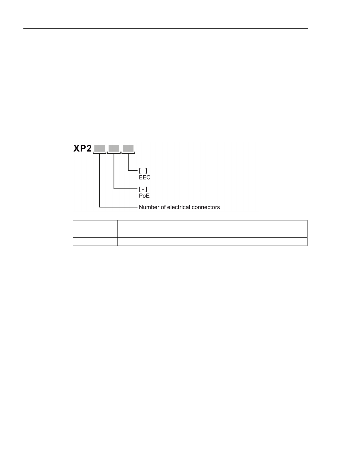
Type designation
Property
Description
EEC
Enhanced Environmental Conditions
PoE
Power over Ethernet
Components of the product
2.1 Product overview
● Industrial Ethernet protocol: PROFINET
● Base bridge mode: 802.1D transparent bridge
● Redundancy mechanism: Ring redundancy
● Trust mode: Trust COS
The type designation of a SCALANCE XP-200 is made up of several parts that have the
following meaning:
The following components are supplied with a SCALANCE XP-200:
● One device
● One product DVD with documentation and software
● Protective caps for all connectors
● 4 screws for mounting on a rack
● Grounding screw
SCALANCE XP-200
18 Operating Instructions, 05/2016, C79000-G8976-C428-01

Description of the device
Accessories
C-PLUG
Component
Description
Article number
figuration data
Varnished (conformal coating)
M12 data plug-in connector
Component
Description
Article number
per package
outlet
per package
nology, socket insert
per package
Data line
Component
Description
Article number
pack of 1
Standard bus cable, TP installation
Sold by the meter
2.1 Product overview
The following accessories are available for SCALANCE XP-200:
C-PLUG Configuration plug,
exchangeable storage medium for con-
Configuration plug,
Exchangeable storage medium for con-
figuration data,
IE FC M12 PLUG PRO 2x2 M12 data plug-in con-
nector for IE FC TP
cables 2x2, IP65/67, Dcoded, axial cable
outlet
IE FC M12 PLUG PRO 4x2 M12 data plug-in con-
nector for IE FC TP
cables 4x2, IP65/67, Xcoded, axial cable
IE FC M12 CABLE
CONNECTOR PRO 4X2
M12 plug-in connector
(X-coded) can be assembled in the field, 8pin, metal housing, FC
fast connection tech-
1 connector
8 connectors
per package
1 connector
8 connectors
per package
1 connector
8 connectors
per package
6GK1 900-0AB00
6GK1 900-0AQ00
6GK1 901-0DB20-6AA0
6GK1 901-0DB20-6AA8
6GK1 901-0DB30-6AA0
6GK1 901-0DB30-6AA8
6GK1 901-0DB40-6AA0
6GK1 901-0DB40-6AA8
SCALANCE XP-200
Operating Instructions, 05/2016, C79000-G8976-C428-01
Connecting cable (M12/RS-
232)
IE FC TP STANDARD CABLE
GP2X2
(PROFINET type A)
Preassembled, serial cable with
M12 and RS-232 plug,
Length: 3 m
cable for connection to FC
OUTLET RJ-45, for universal use,
4-wire, shielded, CAT 5E
6GK5 980-3BC00-0AA5
6XV1 840-2AH10
19

Description of the device
Component
Description
Article number
Sold by the meter
Sold by the meter
cable, flexible wires, shielded, CAT
Sold by the meter
Sold by the meter
Sold by the meter
Sold by the meter
Sold by the meter
RJ-45 Plug 145
M12 plugs (D-coded)
* Available in different lengths
2.1 Product overview
IE FC TP ROBUST
STANDARD CABLE GP 2X2
(PROFINET type A)
IE FC TP ROBUST FLEXIBLE
CABLE GP 2X2
(PROFINET type B)
IE FC TP FLEXIBLE CABLE
GP 2X2
(PROFINET type B)
IE FC TP TRAILING CABLE
2X2
(PROFINET type C)
IE TP TORSION CABLE 2X2
(PROFINET type C)
Standard bus cable, ATPE outer
jacket for connection to FC RJ45
PLUG and FC OUTLET RJ45,
fixed installation, for universal use,
4-wire, shielded, CAT 5
Flexible bus cable, TPE outer
jacket for connection to FC RJ45
PLUG and FC OUTLET RJ45,
flexible wires, 4-wire, shielded,
CAT 5
Flexible bus cable, TP installation
5
Highly flexible bus cable, TP installation cable for connection to FC
OUTLET RJ45, for use in drag
chains, 4-wire, shielded, CAT 5
Highly flexible bus cable, TP installation cable for use in highly flexible applications (torsion), 4-wire
6XV1 841-2A
6XV1 841-2B
6XV1 870-2B
6XV1 840-3AH10
6XV1 870-2F
IE FC TP STANDARD CABLE
GP 4X2
IE FC TP FLEXIBLE CABLE
GP 4X2
IE CONNECTING CABLE
M12-180/IE RJ45
IE CONNECTING CABLE
M12-180/M12-180
Shielded TP installation cable for
connection to IE FC RJ45 PLUG
4X2, CAT 6, AWG 24
Shielded TP installation cable for
connection to IE FC RJ45 PLUG
4X2, flexible wires, CAT 6, 24
AWG
Flexible IE connecting cable, 4wire, preassembled with a 4-pin
M12 plug (D-coded) and an IE FC
Flexible IE connecting cable, 4wire, preassembled with two 4-pin
6XV1 878-2A
6XV1 878-2B
6XV1 871-5T*
6XV1 870-8A*
SCALANCE XP-200
20 Operating Instructions, 05/2016, C79000-G8976-C428-01

Description of the device
Cabinet feedthrough
Component
Description
Article number
pack of 5
pack of 5
pack of 5
Power supply unit
Component
Description
Article number
230 VAC, output 24 VDC/5A IP67
230 VAC, output 24 VDC/8A IP67
* Available in different lengths
Energy cable
Component
Description
Article number
Sold by the meter
Sold by the meter
M12 socket (A-coded)
* Available in different lengths
2.1 Product overview
IE M12 PANEL
FEEDTHROUGH
IE M12 PANEL
FEEDTHROUGH PRO
IE M12 PANEL
FEEDTHROUGH 4X2
Cabinet feedthrough for conversion from
M12 connector technology (D-coded,
IP65) to RJ-45 connector technology
(IP20)
Cabinet feedthrough for conversion from
M12 connector technology (D-coded,
IP65) to M12 connector technology (Dcoded, IP65)
Cabinet feedthrough for conversion from
M12 connector technology (X-coded,
IP65/67) to R-45 connector technology
(X-coded, IP20)
SITOP PSU100P Stabilized power supply, input: 120 to
Stabilized power supply, input: 120 to
6GK1 901-0DM20-2AA5
6GK1 901-0DM30-2AA5
6GK1 901-0DM40-2AA5
6EP1 333-7CA00
6EP1 334-7CA00
Energy cable 2 x 0.75 Energy cable for connection of signaling
contact and power supply 24 VDC,
stranded wire 2 x 0.75 mm2, capable of
trailing, not assembled
Robust Energy Cable 4 x
0,75
M12 PLUG-IN CABLE Flexible plug-in power cable to connect
Energy cable for connection of power
supply 24 VDC, 4-wire stranded 2 x 0.75
mm2, robust, flexible, not assembled
the power supply 24 VDC, 4-wire, preassembled with a 4-pin M12 plug and an
6XV1 812-8A
6XV1 801-2A
6XV1 801-5D*
SCALANCE XP-200
Operating Instructions, 05/2016, C79000-G8976-C428-01
21

Description of the device
Socket
Component
Description
Article number
pack of 3
M12 Power T-Tap
Component
Description
Article number
pack of 5
Rack (ET200PRO)
Component
Description
Article number
pack of 1
pack of 1
pack of 1
pack of 1
pack of 1
pack of 1
pack of 1
pack of 1
pack of 1
pack of 1
pack of 1
pack of 1
2.1 Product overview
IE POWER M12 CABLE
CONNECTOR PRO
SIGNALLING CONTACT
M12 CABLE CONNECTOR
Socket for the 24 V DC power supply. 4pin, A-coded
Socket for the signaling contact, 5-pin,
B-coded
pack of 3
M12 Power T-Tap Power T tap with two M12 sockets and
one M12 plug, see also section "24 VDC
power supply (Page 56)"
Rack narrow Length: 500 mm (ready for installation)
Length: 1000 mm (ready for installation)
6GK1 907-0DC10-6AA3
6GK1 908-0DC10-6AA3
6GK1 907-0DC00-6AA5
6ES7 194-4GA00-0AA0
6ES7 194-4GA60-0AA0
Length: 2000 mm,
Rack wide Length: 500 mm (ready for installation)
Length: 1000 mm (ready for installation)
Length: 2000 mm,
Rack compact narrow Length: 500 mm (ready for installation)
Length: 1000 mm (ready for installation)
Length: 2000 mm,
Rack compact wide Length: 500 mm (ready for installation)
Length: 1000 mm (ready for installation)
Length: 2000 mm,
6ES7 194-4GA20-0AA0
6ES7 194-4GB00-0AA0
6ES7 194-4GB60-0AA0
6ES7 194-4GB20-0AA0
6ES7 194-4GC70-0AA0
6ES7 194-4GC60-0AA0
6ES7 194-4GC20-0AA0
6ES7 194-4GD00-0AA0
6ES7 194-4GD10-0AA0
6ES7 194-4GD20-0AA0
SCALANCE XP-200
22 Operating Instructions, 05/2016, C79000-G8976-C428-01

Description of the device
Spare parts
Component
Description
Article number
Pack of 8 for sockets and 2 for plugs
2.1 Product overview
The following spare parts are available for SCALANCE XP-200:
M12 protective caps Protective caps to protect unused M12 sockets
and plugs
6GK5 980-2FA000AA0
SCALANCE XP-200
Operating Instructions, 05/2016, C79000-G8976-C428-01
23
Description of the device
2.2
Device views
2.2.1
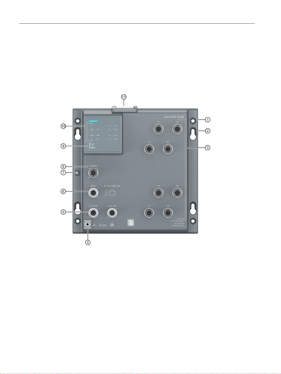
Device view of a SCALANCE XP208 and SCALANCE XP208EEC
①
Cutout for hexagonal nuts
②
Keyhole hang-up mechanism
③ Ethernet ports for Fast Ethernet
④
Grounding point
⑤
Power supply (redundant)
⑥ Signaling contact
⑦
Securing point for covering the serial interface
⑧
Serial interface
⑨ "SELECT / SET" button
⑩
LED display
⑪
2.2 Device views
The following figure shows an overview of the components of the SCALANCE XP208 and
SCALANCE XP208EEC.
Cover for:
• C-PLUG slot
• "RESET" button
SCALANCE XP-200
24 Operating Instructions, 05/2016, C79000-G8976-C428-01

Description of the device
2.2.2
Device view of a SCALANCE XP208PoE EEC
①
Cutout for hexagonal nuts
②
Keyhole hang-up mechanism
③
a
Ethernet ports for Fast Ethernet (P1 - P4)
b
Ethernet ports for Fast Ethernet and PoE (P5 - P8)
④
Grounding point
⑤
Power supply (redundant)
⑥
Signaling contact
⑦
Securing point for covering the serial interface
⑧
Serial interface
⑨
"SELECT / SET" button
⑩
LED display
⑪
2.2 Device views
The following figure shows an overview of the components of the SCALANCE XP208PoE
EEC
Cover for:
• C-PLUG slot
• "RESET" button
SCALANCE XP-200
Operating Instructions, 05/2016, C79000-G8976-C428-01
25
Description of the device
2.2.3
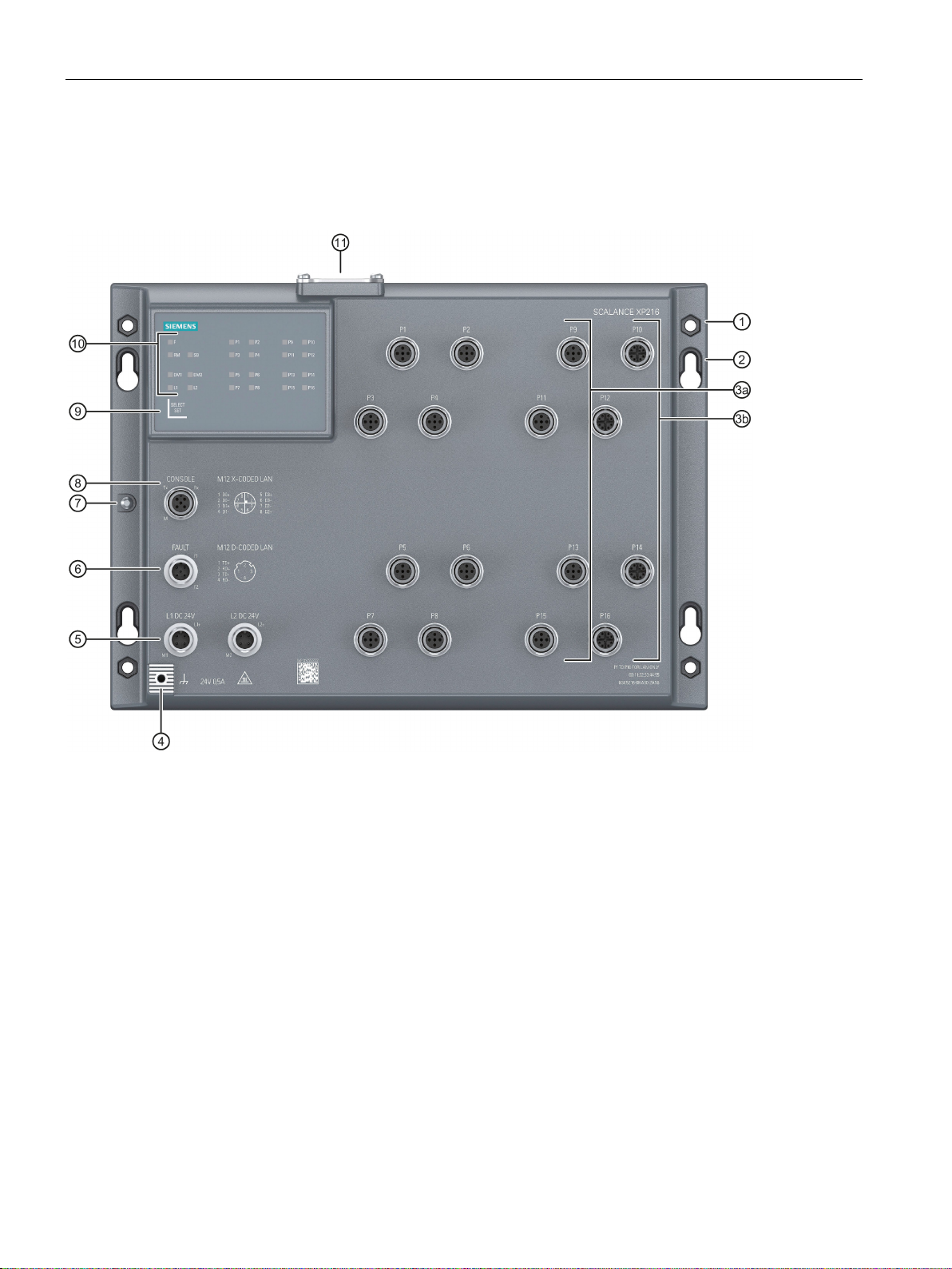
Device view of a SCALANCE XP216 and SCALANCE XP216EEC
①
Cutout for hexagonal nuts
②
Keyhole hang-up mechanism
③
a
Ethernet ports for Fast Ethernet (P1 - P8, P9, P11, P13 and P15)
b
Ethernet ports for Gigabit Ethernet (P10, P12, P14 and P16)
④
Grounding point
⑤
Power supply (redundant)
⑥
Signaling contact
⑦
Securing point for covering the serial interface
⑧
Serial interface
⑨
"SELECT / SET" button
⑩
LED display
⑪
2.2 Device views
The following figure shows an overview of the components of the SCALANCE XP216 and
SCALANCE XP216EEC.
Cover for:
• C-PLUG slot
• "RESET" button
SCALANCE XP-200
26 Operating Instructions, 05/2016, C79000-G8976-C428-01
Description of the device
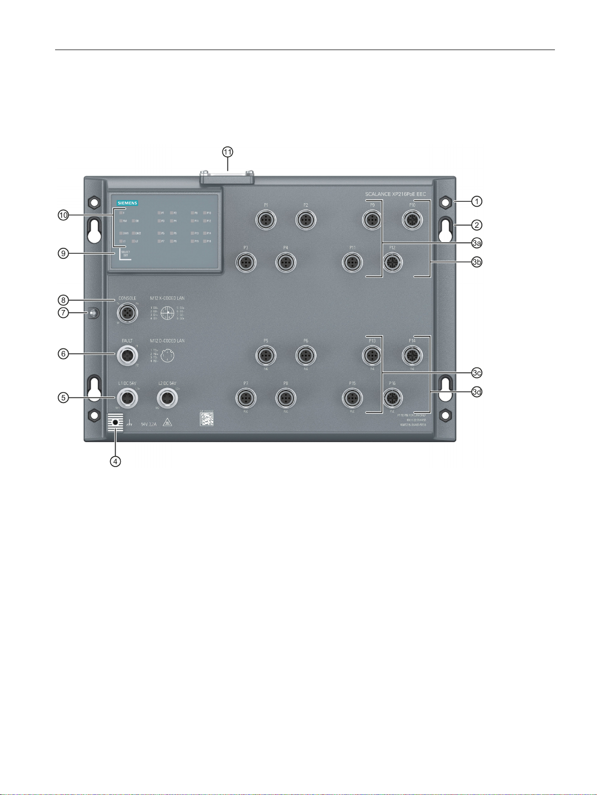
2.2.4
Device view of a SCALANCE XP216PoE EEC
①
Cutout for hexagonal nuts
②
Keyhole hang-up mechanism
③
a
Ethernet ports for Fast Ethernet (P1 - P4, P9 and P11)
b
Ethernet ports for Gigabit Ethernet (P10 und P12)
c
Ethernet ports for Fast Ethernet and PoE (P5 - P8, P13 and P15)
d
Ethernet ports for Gigabit Ethernet and PoE (P14 and P16)
④
Grounding point
⑤
Power supply (redundant)
⑥
Signaling contact
⑦
Securing point for covering the serial interface
⑧
Serial interface
⑨
"SELECT / SET" button
⑩
LED display
⑪
2.2 Device views
The following figure shows an overview of the components of the SCALANCE XP216PoE
EEC.
Cover for:
• C-PLUG slot
• "RESET" button
SCALANCE XP-200
Operating Instructions, 05/2016, C79000-G8976-C428-01
27
Description of the device
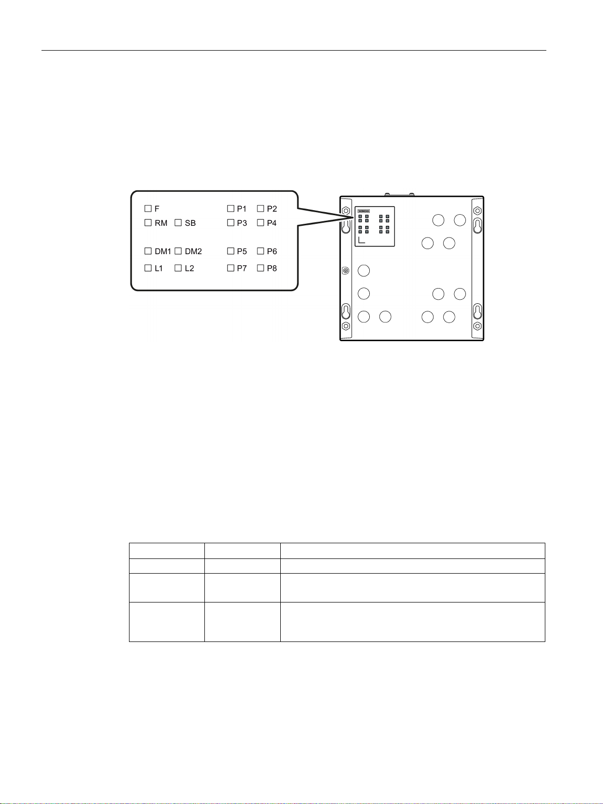
2.3
LED display
2.3.1
Overview
F
LED for displaying the fault/error status
RM
LED for displaying the "redundancy manager" function
SB
LED for displaying the "standby" function
DM1/DM2
LEDs for displaying the display mode
L1/L2
LEDs for displaying the power supply
P
LEDs for displaying the port status *)
2.3.2
"RM" LED
LED color
LED status
Meaning
-
Off
The device is not a redundancy manager.
The ring is working without problems, monitoring is activated.
has switched through.
2.3 LED display
The following figure shows the arrangement of the LEDs.
*) The number of port LEDs depends on the device.
The "RM" LED indicates whether or not the device is a redundancy manager and whether or
not the ring is operating free of error.
Green On The device is a redundancy manager.
Green Flashing The device is a redundancy manager.
An interruption has been detected on the ring and the device
SCALANCE XP-200
28 Operating Instructions, 05/2016, C79000-G8976-C428-01

Description of the device
2.3.3
"SB" LED
LED color
LED status
Meaning
-
Off
The standby function is disabled.
Green
Flashing
The standby function is enabled. The standby section is active.
2.3.4
"F" LED
Meaning during device startup
LED color
LED status
Meaning during device startup
-
Off
Device startup was completed successfully.
Red
On
Device startup is not yet completed or errors have occurred.
Red
Flashing
There are errors in the firmware.
Meaning during operation
LED color
LED status
Meaning during operation
contact is closed.
opened.
2.3.5
LEDs "DM1" and "DM2"
LED color
LED status
Meaning
DM1 LED
DM2 LED
-
Off
Display mode A
Green
On
Off
Display mode B
Green
Off
On
Display mode C
Green
On
Display mode D
Green
Flashing
Off
Display mode E
2.3 LED display
The "SB" LED shows the status of the standby function.
Green On The standby function is enabled. The standby section is pas-
sive.
The "F" LED shows the fault/error status of the device.
- Off The device is operating free of errors. detected The signaling
Red On The device has detected a problem. The signaling contact has
The "DM1" and "DM2" LEDs indicate which display mode is set.
There are 5 display modes (A, B, C, D, and E). Display mode A is the default mode.
Depending on the set display mode, the "L1", "L2" LEDs and the port LEDs show different
information.
SCALANCE XP-200
Operating Instructions, 05/2016, C79000-G8976-C428-01
29
 Loading...