

Siemens SCALANCE X306-1LD FE, SCALANCE X308-2, SCALANCE X307-3, SCALANCE X307-3LD, SCALANCE X308-2LD Operating Instructions Manual
...Page 1

SCALANCE X-300
___________________
___________________
___________________
___________________
___________________
___________________
___________________
___________________
___________________
___________________
___________________
___________________
___________________
SIMATIC NET
Industrial Ethernet Switches
SCALANCE X-300
Operating Instructions
05/2016
A5E01113043
Preface
Safety instructions
1
Introduction
2
Network topologies
3
Description of the device
4
Installation
5
Connecting
6
Configuration, displays and
display elements
7
Technical specifications
8
Approvals, certificates,
standards
9
Accessories
10
Graphics
11
Appendix
A
-20
Page 2

Siemens AG
Division Process Industries and Drives
Postfach 48 48
90026 NÜRNBERG
GERMANY
A5E01113043-20
Ⓟ
Copyright © Siemens AG 2010 - 2016.
All rights reserved
Legal information
Warning notice system
DANGER
indicates that death or severe personal injury will result if proper precautions are not taken.
WARNING
indicates that death or severe personal injury may result if proper precautions are not taken.
CAUTION
indicates that minor personal injury can result if proper precautions are not taken.
NOTICE
indicates that property damage can result if proper precautions are not taken.
Qualified Personnel
personnel qualified
Proper use of Siemens products
WARNING
Siemens products may only be used for the applications described in the catalog and in the relevant technical
ambient conditions must be complied with. The information in the relevant documentation must be observed.
Trademarks
Disclaimer of Liability
This manual contains notices you have to observe in order to ensure your personal safety, as well as to prevent
damage to property. The notices referring to your personal safety are highlighted in the manual by a safety alert
symbol, notices referring only to property damage have no safety alert symbol. These notices shown below are
graded according to the degree of danger.
If more than one degree of danger is present, the warning notice representing the highest degree of danger will
be used. A notice warning of injury to persons with a safety alert symbol may also include a warning relating to
property damage.
The product/system described in this documentation may be operated only by
task in accordance with the relevant documentation, in particular its warning notices and safety instructions.
Qualified personnel are those who, based on their training and experience, are capable of identifying risks and
avoiding potential hazards when working with these products/systems.
Note the following:
documentation. If products and components from other manufacturers are used, these must be recommended
or approved by Siemens. Proper transport, storage, installation, assembly, commissioning, operation and
maintenance are required to ensure that the products operate safely and without any problems. The permissible
All names identified by ® are registered trademarks of Siemens AG. The remaining trademarks in this publication
may be trademarks whose use by third parties for their own purposes could violate the rights of the owner.
We have reviewed the contents of this publication to ensure consistency with the hardware and software
described. Since variance cannot be precluded entirely, we cannot guarantee full consistency. However, the
information in this publication is reviewed regularly and any necessary corrections are included in subsequent
editions.
for the specific
05/2016 Subject to change
Page 3

Preface
Purpose of the Operating Instructions
Validity of the Operating Instructions
Names of the devices in these operating instructions
Classification
Description
Product line (X-300)
Product group
For all devices and variants of a product group, only the product group is used.
Device
For a device, only the device name is used.
Variant
name.
These Operating Instructions describe the design and functions of the compact and modular
Industrial Ethernet Switches of the SCALANCE X-300 product line and support you during
installation, commissioning, and troubleshooting on site.
These Operating Instructions are valid for the following product groups of the SCALANCE X300 product line, see also section Product overview (Page 27).
● X-300
● X-300M
● XR-300M
● X-300EEC
● XR-300M EEC
● X-300M PoE
● XR-300M PoE
● MM900 media modules
● SFP transceiver
Within the SCALANCE X-300 product line, there are product groups, devices and variants.
For all devices and variants of all product groups within the SCALANCE X-300 product
line, the term "IE Switch X-300" is used.
A variant of a device represents a particular design version. They are identified by a
separate order number.
When all variants of a device are meant in the text, "(all)" is often added after the device
SCALANCE X-300
Operating Instructions, 05/2016, A5E01113043-20
3
Page 4

Preface
Overview of the technical documentation of the IE Switches X-300
BAK
Contents
Product group
Type of document
Document identification number
scription
product lines
PH X300/X400
BA X-300
X-300
BAK X-300
A5E00982643A
BAK X-300M
XR-300M
BAK XR-300M
A5E02661171A
X-300EEC
BAK X-300 EEC
A5E02661176A
XR-300M EEC
BAK XR-300M EEC
A5E02630809A
X-300M PoE
BAK X-300M PoE
A5E02630810A
XR-300M PoE
BAK XR-300M PoE
A5E02661178A
MM900 (media modules)
BAK MM900
A5E02630805A
BAK SFP
Notices leaflet
A5E02648904A
The technical documentation of the X-300 product line is divided into hardware and software
and can be found in the following documents:
● PH - Configuration Manual (PDF)
The software is described in the configuration manual (PH) for both product lines X-300
and X-400.
●
- Operating Instructions (compact) on paper
The hardware of each product group is described in the Operating Instructions (compact)
(BAK).
● BA - Operating Instructions (PDF)
The hardware for all product groups and general information can be found in the
Operating Instructions (BA).
Software de-
Hardware description
All devices of the X-300 and X-400
All devices of the X-300 product line
X-300M
SFP (transceivers)
C79000-G89000-C187
A5E01113043
A5E02630801A
A5E02630804A
SCALANCE X-300
4 Operating Instructions, 05/2016, A5E01113043-20
Page 5

Preface
Further documentation
Standards and approvals
Integration in STEP 7 projects
SIMATIC NET glossary
For help on configuration and diagnostics using Web-based management, the CLI command
line interface, or SNMP, refer to the following documentation:
● Configuration Manual SCALANCE X-300 SCALANCE X-400
This configuration manual is available on the following media:
– On the supplied CD
– In 5 languages on the Internet on the pages of Siemens Automation Customer
Support under the following entry ID:
19625108 (http://support.automation.siemens.com/WW/view/en/19625108
● SIMATIC NET - Industrial Ethernet Network manual
This manual is available on the following media:
– On paper under order numbers:
- English version: 6GK1 970-1BA10-0AA1
- German version: 6GK1 970-1BA10-0AA0
– In German and English on the Internet on the pages of Siemens Automation Customer
Support under the following entry ID:
27069465 (http://support.automation.siemens.com/WW/view/en/27069465
If you have questions on the use of SIMATIC NET products, please contact your Siemens
sales partner.
The devices of the SCALANCE X-300 product line meet the requirements for the CE mark.
For more detailed information, refer to section Approvals, certificates, standards (Page 223).
The current GSDML file must be used for integration in STEP 7 V5.4 SP5 projects. This
applies to all products covered by these operating instructions.
)
)
You can obtain the relevant GSD file from the Internet at:
46183514 (http://support.automation.siemens.com/WW/view/en/46183514
You will find the file for the firmware update V3.3.1 for X-300 under entry ID "46183538".
Explanations of many of the specialist terms used in this documentation can be found in the
SIMATIC NET glossary.
SCALANCE X-300
Operating Instructions, 05/2016, A5E01113043-20
)
5
Page 6

Preface
Security information
You will find the SIMATIC NET glossary here:
● SIMATIC NET Manual Collection or product DVD
The DVD ships with certain SIMATIC NET products.
● On the Internet under the following address:
Siemens provides products and solutions with industrial security functions that support the
secure operation of plants, solutions, machines, equipment and/or networks. They are
important components in a holistic industrial security concept. With this in mind, Siemens’
products and solutions undergo continuous development. Siemens recommends strongly
that you regularly check for product updates.
For the secure operation of Siemens products and solutions, it is necessary to take suitable
preventive action (e.g. cell protection concept) and integrate each component into a holistic,
state-of-the-art industrial security concept. Third-party products that may be in use should
also be considered. For more information about industrial security, visit
http://www.siemens.com/industrialsecurity.
To stay informed about product updates as they occur, sign up for a product-specific
newsletter. For more information, visit http://support.automation.siemens.com.
50305045 (http://support.automation.siemens.com/WW/view/en/50305045
)
SCALANCE X-300
6 Operating Instructions, 05/2016, A5E01113043-20
Page 7

Table of contents
Preface ................................................................................................................................................... 3
1 Safety instructions ................................................................................................................................. 15
2 Introduction ........................................................................................................................................... 25
3 Network topologies ............................................................................................................................... 39
4 Description of the device ....................................................................................................................... 47
1.1 Important notes on using the device ....................................................................................... 15
1.2 PELV ....................................................................................................................................... 17
1.3 Important notes on using the device in hazardous areas ....................................................... 18
1.4 Security recommendations ..................................................................................................... 19
2.1 Basics of Ethernet switching ................................................................................................... 25
2.2 Product overview .................................................................................................................... 27
2.2.1 Type designations ................................................................................................................... 27
2.2.2 Designs of the IE Switch X-300 devices ................................................................................. 28
2.2.3 X-300 product group ............................................................................................................... 29
2.2.4 Product group X-300M ............................................................................................................ 30
2.2.5 Product group XR-300M ......................................................................................................... 31
2.2.6 X-300EEC product group ........................................................................................................ 31
2.2.7 XR-300M EEC product group ................................................................................................. 32
2.2.8 Product group X-300M PoE .................................................................................................... 33
2.2.9 Product group XR-300M PoE ................................................................................................. 33
2.2.10 SFP transceiver ...................................................................................................................... 34
2.2.11 MM900 media modules........................................................................................................... 35
3.1 Linear structure ....................................................................................................................... 39
3.2 Star/tree structure ................................................................................................................... 39
3.3 Ring with redundancy manager .............................................................................................. 40
3.4 Redundant coupling of network segments.............................................................................. 44
4.1 Compatibility of SCALANCE X-300 ........................................................................................ 47
4.2 Product groups ........................................................................................................................ 49
4.2.1 X-300 product group ............................................................................................................... 49
4.2.1.1 SCALANCE X304-2FE product characteristics ...................................................................... 49
4.2.1.2 SCALANCE X306-1LD FE product characteristics ................................................................ 50
4.2.1.3 SCALANCE X307-3 product characteristics ........................................................................... 51
4.2.1.4 SCALANCE X307-3LD product characteristics ...................................................................... 52
4.2.1.5 SCALANCE X308-2LH product characteristics ...................................................................... 53
4.2.1.6 SCALANCE X308-2LH+ product characteristics .................................................................... 54
4.2.1.7 SCALANCE X308-2 product characteristics ........................................................................... 55
4.2.1.8 SCALANCE X308-2LD product characteristics ...................................................................... 56
4.2.1.9 SCALANCE X310 product characteristics .............................................................................. 57
SCALANCE X-300
Operating Instructions, 05/2016, A5E01113043-20
7
Page 8

Table of contents
4.2.1.10 SCALANCE X310FE product characteristics ........................................................................ 58
4.2.1.11 SCALANCE X320-1FE product characteristics ..................................................................... 59
4.2.1.12 SCALANCE X320-3LD FE product characteristics ................................................................ 60
4.2.2 Product group X-300M ........................................................................................................... 61
4.2.3 Product group XR-300M ........................................................................................................ 63
4.2.4 X-300EEC product group ....................................................................................................... 65
4.2.4.1 Characteristics of the X-300EEC product group .................................................................... 65
4.2.5 XR-300M EEC product group ................................................................................................ 70
4.2.5.1 Product characteristics of the SCALANCE XR324-4M EEC ................................................. 70
4.2.6 Product group X-300M PoE ................................................................................................... 71
4.2.6.1 SCALANCE X308-2M PoE product characteristics ............................................................... 71
4.2.7 Product group XR-300M PoE ................................................................................................ 73
4.2.7.1 SCALANCE XR324-4M PoE product characteristics ............................................................ 73
4.2.8 MM900 media modules .......................................................................................................... 74
4.2.8.1 MM992-2CUC product characteristics ................................................................................... 74
4.2.8.2 MM992-2CU product characteristics...................................................................................... 75
4.2.8.3 MM992-2VD product characteristics ...................................................................................... 75
4.2.8.4 MM992-2M12 product characteristics .................................................................................... 76
4.2.8.5 MM992-2SFP / MM992-2SFP (C) product properties ........................................................... 77
4.2.8.6 MM991-2 product characteristics ........................................................................................... 77
4.2.8.7 MM991-2FM product characteristics...................................................................................... 78
4.2.8.8 MM991-2LD product characteristics ...................................................................................... 78
4.2.8.9 MM991-2 (SC) product characteristics .................................................................................. 79
4.2.8.10 MM991-2LD (SC) product characteristics .............................................................................. 79
4.2.8.11 MM991-2LH+ (SC) product characteristics............................................................................ 80
4.2.8.12 MM991-2P product characteristics ........................................................................................ 80
4.2.8.13 MM992-2 product characteristics ........................................................................................... 81
4.2.8.14 MM992-2LD product characteristics ...................................................................................... 82
4.2.8.15 MM992-2LH product characteristics ...................................................................................... 82
4.2.8.16 MM992-2LH+ product characteristics .................................................................................... 83
4.2.8.17 MM992-2ELH product characteristics .................................................................................... 83
4.2.8.18 General notes on MM900 ...................................................................................................... 83
4.2.9 SFP transceiver...................................................................................................................... 85
4.2.9.1 SCALANCE SFP991-1 product characteristics ..................................................................... 85
4.2.9.2 SCALANCE SFP991-1LD product characteristics ................................................................. 85
4.2.9.3 SCALANCE SFP991-1LH+ product characteristics .............................................................. 86
4.2.9.4 SCALANCE SFP992-1 product characteristics ..................................................................... 86
4.2.9.5 SCALANCE SFP992-1LD product characteristics ................................................................. 86
4.2.9.6 SCALANCE SFP992-1LH product characteristics ................................................................. 87
4.2.9.7 SCALANCE SFP992-1LH+ product characteristics .............................................................. 87
4.2.9.8 SCALANCE SFP992-1ELH product characteristics .............................................................. 87
4.2.9.9 General notes on SFP ........................................................................................................... 88
4.2.9.10 Supported wavelengths of the SFPs ..................................................................................... 88
4.3 Interfaces and signaling contact of the switches ................................................................... 89
4.3.1 Ethernet interfaces - electrical ports ...................................................................................... 89
4.3.1.1 10Base-T / 100Base-TX ........................................................................................................ 89
4.3.1.2 1000Base-T ............................................................................................................................ 90
4.3.1.3 Power over Ethernet (PoE) .................................................................................................... 91
4.3.1.4 Ports of the X308-2M PoE ..................................................................................................... 92
4.3.1.5 PoE ports ............................................................................................................................... 93
4.3.1.6 Isolation between the TP ports .............................................................................................. 93
4.3.2 Ethernet interfaces - optical ports .......................................................................................... 93
SCALANCE X-300
8 Operating Instructions, 05/2016, A5E01113043-20
Page 9

Table of contents
5 Installation .......................................................................................................................................... 105
6 Connecting ......................................................................................................................................... 127
4.3.2.1 1000Base-SX .......................................................................................................................... 93
4.3.2.2 1000Base-LX / 100Base-FX ................................................................................................... 94
4.3.3 Signaling contact ..................................................................................................................... 95
4.4 C-PLUG (configuration plug) .................................................................................................. 95
4.5 Components of the product .................................................................................................... 99
4.5.1 Components of the product .................................................................................................... 99
4.5.2 X-300M components of the product ........................................................................................ 99
4.5.3 Components of the XR-300M product .................................................................................. 100
4.5.4 X-300EEC product components ........................................................................................... 101
4.5.5 Components of the XR-300M EEC product .......................................................................... 101
4.5.6 Components of the X308-2M PoE product ........................................................................... 102
4.5.7 Components of the XR-324-4M PoE product ....................................................................... 103
4.5.8 Components shipped with the MM900 product .................................................................... 103
4.5.9 Components shipped with the SFP product ......................................................................... 103
5.1 Overview of the methods of installation ................................................................................ 106
5.2 Installing a switch .................................................................................................................. 107
5.2.1 Installation on a DIN rail ........................................................................................................ 107
5.2.2 Installation on a standard rail ................................................................................................ 108
5.2.3 Wall mounting ....................................................................................................................... 110
5.2.4 19" rack mounting ................................................................................................................. 111
5.2.5 19" rack mounting - X-300EEC product group ..................................................................... 115
5.2.6 19" rack mounting - XR-300M EEC product group ............................................................... 116
5.3 Inserting media modules and SFP transceivers ................................................................... 120
5.3.1 Installation and removal of media modules .......................................................................... 120
5.3.2 SFP installation in SFP media module ................................................................................. 124
6.1 Wiring rules ........................................................................................................................... 127
6.2 Connecting the switch ........................................................................................................... 127
6.3 Connecting media modules/SFPs ........................................................................................ 129
6.4 Connecting the grounding ..................................................................................................... 130
6.4.1 Connecting the functional ground (XR-300M EEC) .............................................................. 130
6.4.2 Grounding of the X-300EEC ................................................................................................. 130
6.5 Power supply ........................................................................................................................ 132
6.5.1 24 VDC power supply ........................................................................................................... 132
6.5.1.1 24 VDC safety extra low voltage ........................................................................................... 132
6.5.1.2 24 VDC - product group X-300 ............................................................................................. 133
6.5.1.3 12 / 24 VDC - product group X-300M ................................................................................... 134
6.5.1.4 24 VDC - product group XR-300M ........................................................................................ 134
6.5.1.5 24 VDC - product group X-300EEC ...................................................................................... 134
6.5.1.6 24 VDC - product group X-300M PoE .................................................................................. 135
6.5.1.7 24 VDC - XR-300M PoE product group ................................................................................ 135
6.5.1.8 Connector for redundant power supply ................................................................................. 135
6.5.1.9 Connecting a redundant power supply to the XR300-EEC .................................................. 137
6.5.2 100 to 240 VAC power supply .............................................................................................. 139
6.5.2.1 100 ... 240 V - product group XR-300M ................................................................................ 139
SCALANCE X-300
Operating Instructions, 05/2016, A5E01113043-20
9
Page 10

Table of contents
7 Configuration, displays and display elements ....................................................................................... 147
8 Technical specifications ....................................................................................................................... 155
6.5.2.2 100 to 240 VAC - product group X-300EEC ........................................................................ 139
6.5.2.3 100 to 240 VAC - XR-300M EEC product group ................................................................. 140
6.5.2.4 100 to 240 VAC XR-300M PoE product group .................................................................... 140
6.5.2.5 Fitting the connector for 100 to 240 V AC ............................................................................ 140
6.5.2.6 Connecting the 100 to 240 VAC power supply .................................................................... 142
6.5.2.7 Connecting the power supply 100 to 240 VAC to X-300EEC / XR-300M EEC ................... 142
6.5.2.8 Connecting the 100 to 240 V AC power supply with the XR-300M PoE ............................. 144
6.6 Signaling contact .................................................................................................................. 145
6.6.1 24 VDC signaling contact ..................................................................................................... 145
6.6.2 Signaling contact 100 to 240 VAC / 60 to 250 VDC (X-300EEC) ........................................ 146
7.1 Assignment of slot numbers ................................................................................................. 147
7.2 Show Location...................................................................................................................... 148
7.3 XR-300 diagnostics port ....................................................................................................... 148
7.4 The SET / SELECT button ................................................................................................... 149
7.5 LED display .......................................................................................................................... 151
8.1 Overview of operating temperatures for SCALANCE X-300 ............................................... 155
8.2 X-300 technical specifications .............................................................................................. 156
8.2.1 Construction, installation and environmental conditions ...................................................... 157
8.2.2 Connectors and electrical data ............................................................................................ 158
8.2.3 Cable lengths ....................................................................................................................... 161
8.2.4 Other properties ................................................................................................................... 163
8.3 X-300M technical specifications ........................................................................................... 164
8.3.1 Construction, installation and environmental conditions ...................................................... 164
8.3.2 Connectors and electrical data ............................................................................................ 166
8.3.3 Cable lengths ....................................................................................................................... 167
8.3.4 Other properties ................................................................................................................... 168
8.4 XR-300M technical specifications ........................................................................................ 170
8.4.1 Construction, installation and environmental conditions ...................................................... 170
8.4.2 Connectors and electrical data ............................................................................................ 172
8.4.3 Cable lengths ....................................................................................................................... 173
8.4.4 Block architecture................................................................................................................. 174
8.4.5 Other properties ................................................................................................................... 175
8.5 Technical specifications for X-300EEC ................................................................................ 177
8.5.1 Construction, installation and environmental conditions ...................................................... 177
8.5.2 Connectors and electrical data ............................................................................................ 179
8.5.3 Cable lengths ....................................................................................................................... 181
8.5.4 Other properties ................................................................................................................... 182
8.6 XR-300M EEC technical specifications ............................................................................... 183
8.6.1 Construction, installation and environmental conditions ...................................................... 184
8.6.2 Connectors and electrical data ............................................................................................
186
8.6.3 Cable lengths ....................................................................................................................... 188
8.6.4 Block architecture................................................................................................................. 189
8.6.5 Other properties ................................................................................................................... 190
SCALANCE X-300
10 Operating Instructions, 05/2016, A5E01113043-20
Page 11

Table of contents
9 Approvals, certificates, standards ........................................................................................................ 223
8.7 X-300M PoE technical specifications .................................................................................... 191
8.7.1 Construction, installation and environmental conditions ....................................................... 191
8.7.2 Connectors and electrical data ............................................................................................. 193
8.7.3 Cable lengths ........................................................................................................................ 195
8.7.4 Other properties .................................................................................................................... 196
8.8 XR-300M PoE technical specifications ................................................................................. 197
8.8.1 Construction, installation and environmental conditions ....................................................... 198
8.8.2 Connectors and electrical data ............................................................................................. 200
8.8.3 Cable lengths ........................................................................................................................ 202
8.8.4 Block architecture ................................................................................................................. 203
8.8.5 Other properties .................................................................................................................... 204
8.9 MM900 technical specifications ............................................................................................ 205
8.9.1 Construction, installation and environmental conditions ....................................................... 205
8.9.2 Connectors and electrical data ............................................................................................. 208
8.9.3 Cable lengths ........................................................................................................................ 210
8.9.4 Other properties .................................................................................................................... 214
8.10 SFP technical specifications ................................................................................................. 215
8.10.1 Construction, installation and environment ........................................................................... 215
8.10.2 Connectors and electrical data ............................................................................................. 217
8.10.3 Cable lengths ........................................................................................................................ 220
8.10.4 Other properties .................................................................................................................... 221
9.1 X-300 product group ............................................................................................................. 223
9.1.1 X-300 approvals, certificates ................................................................................................ 223
9.1.2 X-300 type plate .................................................................................................................... 227
9.1.3 SCALANCE X-300 declaration of conformity........................................................................ 227
9.1.4 X-300 FDA and IEC approvals ............................................................................................. 227
9.1.5 Overview of the X-300 approvals .......................................................................................... 228
9.1.6 X-300 mechanical stability (in operation) .............................................................................. 229
9.2 Product group X-300M .......................................................................................................... 229
9.2.1 X-300M approvals, certificates ............................................................................................. 229
9.2.2 X-300M type plate ................................................................................................................. 233
9.2.3 SCALANCE X-300 declaration of conformity........................................................................ 233
9.2.4 X-300M FDA and IEC approvals .......................................................................................... 234
9.2.5 Overview of X-300M approvals ............................................................................................. 234
9.2.6 X-300M mechanical stability (in operation) ........................................................................... 235
9.3 Product group XR-300M ....................................................................................................... 235
9.3.1 XR-300M approvals, certificates ........................................................................................... 235
9.3.2 XR-300M type plate .............................................................................................................. 240
9.3.3 SCALANCE X-300 declaration of conformity........................................................................ 240
9.3.4 XR-300M FDA and IEC approvals ........................................................................................ 241
9.3.5 Overview of XR-300M approvals .......................................................................................... 241
9.3.6 XR-300M mechanical stability (in operation) ........................................................................ 242
9.4 X-300EEC product group ...................................................................................................... 243
9.4.1 X-300EEC approvals and certificates ................................................................................... 243
9.4.2 SCALANCE X-300 declaration of conformity........................................................................ 247
9.4.3 Overview of the approvals for the X-300EEC ....................................................................... 248
9.4.4 X-300EEC mechanical stability (in operation) ...................................................................... 248
SCALANCE X-300
Operating Instructions, 05/2016, A5E01113043-20
11
Page 12

Table of contents
10 Accessories ......................................................................................................................................... 281
11 Graphics .............................................................................................................................................. 283
A Appendix ............................................................................................................................................. 311
9.5 XR-300M EEC product group .............................................................................................. 249
9.5.1 XR-300M EEC approvals, certificates ................................................................................. 249
9.5.2 SCALANCE X-300 declaration of conformity ....................................................................... 253
9.5.3 Overview of XR-300M EEC approvals ................................................................................. 254
9.5.4 XR-300M EEC mechanical stability (in operation) ............................................................... 254
9.6 Product group X-300M PoE ................................................................................................. 255
9.6.1 X-300M PoE approvals, certificates ..................................................................................... 255
9.6.2 SCALANCE X-300 declaration of conformity ....................................................................... 259
9.6.3 Overview of X-300M PoE approvals .................................................................................... 259
9.6.4 X-300M PoE mechanical stability in operation .................................................................... 259
9.7 Product group XR-300M PoE .............................................................................................. 260
9.7.1 XR-300M PoE approvals, certificates .................................................................................. 260
9.7.2 SCALANCE X-300 declaration of conformity ....................................................................... 263
9.7.3 Overview of XR-300M PoE approvals ................................................................................. 264
9.7.4 XR-300M PoE mechanical stability in operation .................................................................. 264
9.8 MM900 product group .......................................................................................................... 265
9.8.1 MM900 approvals, certificates ............................................................................................. 265
9.8.1.1 ATEX (KEMA 07 ATEX0145 X) ........................................................................................... 267
9.8.2 MM900 declaration of conformity ......................................................................................... 270
9.8.3 Overview of the MM900 approvals ...................................................................................... 270
9.8.4 MM900 FDA and IEC approvals .......................................................................................... 272
9.9 Product group SFP .............................................................................................................. 273
9.9.1 Approvals, certificates .......................................................................................................... 273
9.9.2 SFP type plate...................................................................................................................... 277
9.9.3 SFP declaration of conformity .............................................................................................. 277
9.9.4 SFP FDA and IEC approvals ............................................................................................... 278
9.9.5 Overview of the SFP approvals ........................................................................................... 278
9.9.6 SFP mechanical stability (in operation) ............................................................................... 280
10.1 Accessories .......................................................................................................................... 281
11.1 Dimension drawing .............................................................................................................. 283
11.2 X-300M dimension drawings ................................................................................................ 289
11.3 XR-300M dimension drawings ............................................................................................. 291
11.4 X-300EEC dimension drawings ........................................................................................... 294
11.5 XR-300M EEC dimension drawings..................................................................................... 296
11.6 MM900 dimension drawings ................................................................................................ 302
11.7 SFP dimension drawings ..................................................................................................... 305
11.8 X-300M PoE dimension drawings ........................................................................................ 306
11.9 XR-300M PoE dimension drawings ..................................................................................... 309
A.1 TP port ................................................................................................................................. 311
A.2 The connector system M12/X coded according to IEC 61076-2-109 .................................. 313
SCALANCE X-300
12 Operating Instructions, 05/2016, A5E01113043-20
Page 13

Table of contents
Index................................................................................................................................................... 321
A.3 Fitting the IE FC RJ-45 Plug ................................................................................................. 314
A.4 Electrical tests (EEC devices) ............................................................................................... 316
A.5 EMC-compatible installation of electrical Industrial Ethernet or PROFIBUS cabling ........... 317
A.6 Equipotential bonding ........................................................................................................... 318
SCALANCE X-300
Operating Instructions, 05/2016, A5E01113043-20
13
Page 14

Table of contents
SCALANCE X-300
14 Operating Instructions, 05/2016, A5E01113043-20
Page 15

1
1.1
Important notes on using the device
Safety notices on the use of the device
General information
WARNING
Opening the device
WARNING
Safety extra low voltage (only devices with 24 VDC power supply)
WARNING
For use in an environment with pollution level 2
The following safety notices must be adhered to when setting up and operating the device
and during all associated work such as installation, connecting up, replacing or opening the
device.
DO NOT OPEN WHEN ENERGIZED.
The equipment is designed for operation with Safety Extra-Low Voltage (SELV) by a
Limited Power Source (LPS).
This means that only SELV / LPS (Limited Power Source) complying with IEC 60950-1 / EN
60950-1 / VDE 0805-1 must be connected to the power supply terminals. The power supply
unit for the equipment power supply must comply with NEC Class 2, as described by the
National Electrical Code (r) (ANSI / NFPA 70).
If the equipment is connected to a redundant power supply (two separate power supplies),
both must meet these requirements.
A power source that supplies safety extra low voltage combined with a following NEC Class
2 power limiter also meets the requirements according to IEC 60950-1 / EN 60950-1 / VDE
0805-1 or NEC Class 2. A suitable power limiter is for example the redundancy module
SITOP PSE202U NEC Class 2 (article number 6EP1962-2BA00).
SCALANCE X-300
Operating Instructions, 05/2016, A5E01113043-20
15
Page 16
Safety instructions
WARNING
Safety notice for connectors with LAN (Local Area Network) marking
General notices about use in hazardous areas
WARNING
Risk of explosion when connecting or disconnecting the device
WARNING
Replacing components
WARNING
Requirements for the cabinet/enclosure
WARNING
Opening the device
1.1 Important notes on using the device
A LAN or LAN segment, with all its associated interconnected equipment, shall be entirely
contained within a single low-voltage power distribution and within a single building. The
LAN is considered to be in an "environment A" according to IEEE802.3 or "environment 0"
according to IEC TR 62102, respectively. Never connect directly to TNV-circuits (Telephone
Network) or WAN (Wide Area Network).
EXPLOSION HAZARD
DO NOT CONNECT OR DISCONNECT EQUIPMENT WHEN A FLAMMABLE OR
COMBUSTIBLE ATMOSPHERE IS PRESENT.
EXPLOSION HAZARD
SUBSTITUTION OF COMPONENTS MAY IMPAIR SUITABILITY FOR CLASS I, DIVISION
2 OR ZONE 2.
When used in hazardous environments corresponding to Class I, Division 2 or Class I,
Zone 2, the device must be installed in a cabinet or a suitable enclosure.
DO NOT OPEN WHEN ENERGIZED.
SCALANCE X-300
16 Operating Instructions, 05/2016, A5E01113043-20
Page 17

Safety instructions
Safety notices on use in hazardous areas according to ATEX and IECEx
WARNING
Requirements for the cabinet/enclosure
WARNING
Suitable cables for temperatures in excess of 70 °C
WARNING
Protection against transient voltage surges
1.2
PELV
Note
Safety extra-low voltage
The supply of the devices by PELV (Protective Extra Low Voltage) according to DIN VDE
0100
exceed the voltage limits 25 VAC or 60 VDC.
1.2 PELV
To comply with EC Directive 94/9 (ATEX95) or the conditions of IECEx, this enclosure must
meet the requirements of at least IP54 in compliance with EN 60529.
The fiber-optic bus connections labeled SCALANCE MM900 (see type plate) may also be
led through a hazardous area zone1 (see also Auto-Hotspot, section "Explosion Protection
Directive (ATEX)").
If the cable or conduit entry point exceeds 70°C or the branching point of conductors
exceeds 80°C, special precautions must be taken.
If the equipment is operated in an air ambient in excess of 50 °C, only use cables with
admitted maximum operating temperature of at least 80 °C.
Provisions shall be made to prevent the rated voltage from being exceeded by transient
voltage surges of more than 40%. This criterion is fulfilled, if supplies are derived from
SELV (Safety Extra-Low Voltage) only.
-410 or IEC 60364-4-41 is permitted when the generated nominal voltage does not
SCALANCE X-300
Operating Instructions, 05/2016, A5E01113043-20
17
Page 18

Safety instructions
1.3
Important notes on using the device in hazardous areas
WARNING
WARNING - EXPLOSION HAZARD -
WARNING
Restricted area of application
WARNING
Restricted area of application
Note on devices with power supply 100 to 240 V AC
WARNING
Danger from line voltage
WARNING
Devices with a 100 to 240 V AC power supply do not have an ATEX or IECEx approval.
NOTICE
Securing cables with dangerous voltage
1.3 Important notes on using the device in hazardous areas
DO NOT DISCONNECT WHILE CIRCUIT IS LIVE UNLESS AREA IS KNOWN TO BE
NON-HAZARDOUS.
This equipment is suitable for use in Class I, Division 2, Groups A, B, C and D or nonhazardous locations only.
This equipment is suitable for use in Class I, Zone 2, Group IIC or non-hazardous locations
only.
The supply voltage for the devices listed is 100 to 240 VAC.
This device can only function correctly and safely if it is transported, stored, set up, and
installed correctly, and operated and maintained as recommended.
Connecting and disconnecting may only be performed by an electrical specialist.
Connect or disconnect power supply cables only when the power is turned off.
Devices with a 100 to 240 V AC power supply are not approved for use in hazardous areas
according to EC-RL-94/9 ATEX or IECEx.
Make sure that the connector cannot be released accidentally by pulling on the connecting
cable. Lay the cables in cable ducts or cable channels and secure the cables, where
necessary, with cable ties.
SCALANCE X-300
18 Operating Instructions, 05/2016, A5E01113043-20
Page 19

Safety instructions
Safety requirements for installation
1.4
Security recommendations
General
Physical access
1.4 Security recommendations
According to the IEC 61131-2 standard and therefore in accordance with the EU directive
2006/95/EC (Low Voltage Directive), the devices are "open equipment" and in accordance
with UL/CSA certification, they are an "open type".
To fulfill requirements for safe operation with regard to mechanical stability, flame
retardation, stability, and shock-hazard protection, the following alternative types of
installation are specified:
● Installation in a suitable cabinet.
● Installation in a suitable enclosure.
● Installation in a suitably equipped, enclosed control room.
To prevent unauthorized access, note the following security recommendations.
● You should make regular checks to make sure that the device meets these
recommendations and/or other security guidelines.
● Evaluate your plant as a whole in terms of security. Use a cell protection concept with
suitable products.
● When confidential zones are used, the internal and external network are disconnected, an
attacker cannot access the data from the outside.
● Operate the device only within a protected network area.
● Use VPN to encrypt and authenticate communication from and to the devices.
● For data transmission via a non-secure network use an encrypted VPN tunnel (IPsec).
● For operation of the device in a non-secure infrastructure no product liability will be
accepted.
● Separate connections correctly (WBM. Telnet, SSH etc.).
● Limit physical access to the device to qualified personnel.
The memory card or the C-PLUG contains sensitive data such as certificates, keys etc.
that can be read out and modified.
● Lock unused physical ports on the device. Unused ports can be used to gain forbidden
access to the plant.
SCALANCE X-300
Operating Instructions, 05/2016, A5E01113043-20
19
Page 20

Safety instructions
Software (security functions)
See also
Passwords
Keys and certificates
1.4 Security recommendations
● Keep the software up to date. Check regularly for security updates of the product.
You will find information on this on the Internet pages "Industrial Security"
● Inform yourself regularly about security advisories and bulletins published by Siemens
productCERT.
● Only activate protocols that you really require to use the device.
● Restrict access to the device with a firewall or rules in an access control list (ACL -
Access Control List).
● Restrict access to the management of the device with rules in an access control list
(ACL).
● The option of VLAN structuring provides good protection against DoS attacks and
unauthorized access. Check whether this is practical or useful in your environment.
● Enable logging functions. Use the central logging function to log changes and access
attempts centrally. Check the logging information regularly.
● Configure a Syslog server to forward all logs to a central location.
www.siemens.com/industrialsecurity (http://www.siemens.com/industrialsecurity)
● Define rules for the use of devices and assignment of passwords.
● Regularly update passwords and keys to increase security.
● Change all default passwords for users before you operate the device.
● Only use passwords with a high password strength. Avoid weak passwords for example
● Make sure that all passwords are protected and inaccessible to unauthorized personnel.
● Do not use the same password for different users and systems or after it has expired.
This section deals with the security keys and certificates you require to set up SSL.
● We strongly recommend that you create your own SSL certificates and make them
password1, 123456789, abcdefgh.
available.
There are preset certificates and keys on the device. The preset and automatically
created SSL certificates are self-signed. We recommend that you use SSL certificates
signed either by a reliable external or by an internal certification authority.
The device has an interface via which you can import the certificates and keys.
● Use the certification authority including key revocation and management to sign the
certificates.
SCALANCE X-300
20 Operating Instructions, 05/2016, A5E01113043-20
Page 21

Safety instructions
Secure/non-secure protocols
1.4 Security recommendations
● Handle user-defined private keys with great caution if you use user-defined SSH or SSL
keys.
● Verify certificates and fingerprints on the server and client to avoid "man in the middle"
attacks.
● We recommend that you use certificates with a key length of 2048 bits.
● Change keys and certificates immediately, if there is a suspicion of compromise.
● Avoid or disable non-secure protocols, for example Telnet and TFTP. For historical
reasons, these protocols are still available, however not intended for secure applications.
Use non-secure protocols on the device with caution.
● Avoid or disable non-secure protocols. Check whether use of the following protocols is
necessary:
– PNIO
– Broadcast pings
– Non authenticated and unencrypted interfaces
– ICMP (redirect)
– MRP, HRP
– GMRP and IGMP
– LLDP
– Syslog
– RADIUS
– DHCP Options 66/67
– TFTP
– GMRP and GVRP
– Multicast routing
● The following protocols provide secure alternatives:
– SNMPv1/v2 → SNMPv3
Check whether use of SNMPv1 is necessary. SNMPv1 is classified as non-secure.
Use the option of preventing write access. The product provides you with suitable
setting options.
If SNMP is enabled, change the community names. If no unrestricted access is
necessary, restrict access with SNMP.
Use SNMPv3 in conjunction with passwords.
– HTTP → HTTPS
– TFTP → FTPS
– Telnet → SSH
– SNTP → NTP
SCALANCE X-300
Operating Instructions, 05/2016, A5E01113043-20
21
Page 22

Safety instructions
Available protocols per port
Protocol
Port number
Port status
Note
With some protocols the port may be open although the corresponding protocol
disabled, for example TFTP.
Default status of the port
Authentication
1.4 Security recommendations
● Use secure protocols when access to the device is not prevented by physical protection
measures.
● To prevent unauthorized access to the device or network, take suitable protective
measures against non-secure protocols.
● If you require non-secure protocols and services, operate the device only within a
protected network area.
● Restrict the services and protocols available to the outside to a minimum.
● For the DCP function, enable the "DCP read-only" mode after commissioning.
The following list provides you with an overview of the open ports on this device. Keep this in
mind when configuring a firewall.
The table includes the following columns:
●
All protocols that the device supports
●
Port number assigned to the protocol
●
– Open
The port is always open and cannot be closed.
– Open (when configured)
The port is open if it has been configured.
is
●
– Open
As default the port is open.
– Closed
As default the port is closed.
●
Specifies whether or not the protocol is authenticated during access.
SCALANCE X-300
22 Operating Instructions, 05/2016, A5E01113043-20
Page 23

Safety instructions
Protocol
Port number
Port status
Default status of
the port
Authentication
SSH
TCP/22
Open
Open
Yes
HTTP
HTTPS
TCP/443
Open
Open
Yes
SNTP
NTP (secure)
(when configured)
SNMP
(when configured)
PROFINET IO
UDP/1026, 1027
PROFINET IO
Service
1.4 Security recommendations
TCP/80 Open
(when configured)
UDP/161 Open
UDP/123 Open
UDP/34964
TCP/84 Open Open No
Open Open No
Open Yes
Closed No
Open Yes
SCALANCE X-300
Operating Instructions, 05/2016, A5E01113043-20
23
Page 24

Safety instructions
1.4 Security recommendations
SCALANCE X-300
24 Operating Instructions, 05/2016, A5E01113043-20
Page 25

2
2.1
Basics of Ethernet switching
Ethernet switching
The need for Industrial Ethernet switches
Ethernet switches forward data packets directly from the input port to the appropriate output
port during data exchange based on the address information. Ethernet switches operate on a
direct delivery basis.
Essentially, switches have the following functions:
● Connecting collision domains / subnets
Since repeaters and star couplers (hubs) operate at the physical level, their use is
restricted to the span of a collision domain. Switches connect collision domains. Their use
is therefore not restricted to the maximum span of a repeater network. On the contrary,
extremely large networks with very large spans are possible with switches. The distances
achieved depend on the fiber-optic interfaces used in the devices and the FO fibers used
(see technical specifications).
● Load containment
By filtering the data traffic based on the Ethernet (MAC) addresses, local data traffic
remains local. In contrast to repeaters or hubs, which distribute data unfiltered to all ports
/ network nodes, switches operate selectively. Only data intended for nodes in other
subnets is switched from the input port to the appropriate output port of the switch. To
make this possible, a table assigning Ethernet (MAC) addresses to output ports is
created by the switch in a "teach-in" mode.
● Limiting the propagation of errors to the subnet involved.
By checking the validity of a data packet on the basis of the checksum which each data
packet contains, the switch ensures that bad data packets are not transported further.
Collisions in one network segment are not passed on to other segments.
With over 95% of LANs based on Ethernet, this is the most commonly used technology. The
use of switches is particularly important: They allow extensive networks with large numbers
of nodes to be set up, increase the data throughput, and simplify network expansion.
The IE Switches X-300 from SIMATIC NET are designed for use in high-speed plant
networks that will also meet future requirements. With the HRP redundancy function and
standby linking of rings, high network availability can be achieved. HRP and standby link
reconfigures the network within 300 ms. Support of IT standards such as VLAN, RSTP,
IGMP, and GARP makes seamless integration of automation networks in existing office
networks possible.
The IE Switches X-300 are designed for use in switching cubicles and cabinets.
SCALANCE X-300
Operating Instructions, 05/2016, A5E01113043-20
25
Page 26

Introduction
Technical options (network topologies)
2.1 Basics of Ethernet switching
The IE Switches X-300 simplify the expansion of a network regardless of the network
topology.
You can use an IE Switch X-300 in the following network topologies:
● Linear structure
● Star/tree structure
● Ring with redundancy manager
The maximum cable length is 70 km for single mode gigabit transmission. A mixed topology
consisting of IE Switch X-300 devices and OSMs/ESMs is possible at the electrical ports. A
mixed topology consisting of IE Switch X-300 devices and an OSM via the optical ports is not
possible.
Using an IE Switch X-300 as the redundancy manager in a ring with redundancy manager
provides greater availability. If there is an interruption on the connection between these
switches, the IE Switch X-300 used as redundancy manager acts like a switch and in a very
short time creates a line from the ring. As a result, a functional, end-to-end structure is
restored. For information on this topic, refer to the Configuration Manual "SIMATIC NET Industrial Ethernet Switches SCALANCE X-300 SCALANCE X-400."
SCALANCE X-300
26 Operating Instructions, 05/2016, A5E01113043-20
Page 27
Introduction
2.2
Product overview
2.2.1
Type designations
Structure of the type designation
Interface
Property
FE
Electrical RJ-45 port for 10/100 Mbps.
[-]
Electrical RJ-45 port for 10/100 Mbps or 10/100/1000 Mbps.
Interface
Property
FE
SC port 100 Mbps multimode FO cable (up to max. 5 km).
LD FE
SC port 100 Mbps single mode FO cable (up to max. 26 km).
[-]
SC port 1000 Mbps multimode FO cable (up to max. 750 m).
LD
SC port 1000 Mbps single mode FO cable (up to max. 10 km).
LH+
SC port 1000 Mbps single mode FO cable (up to max. 70 km).
2.2 Product overview
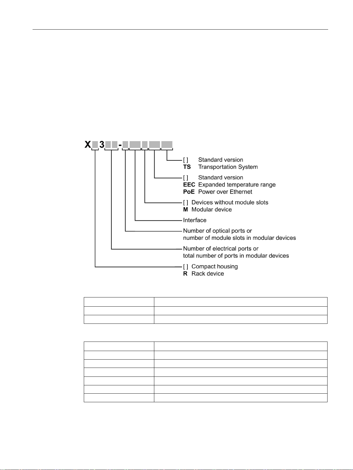
The type designation of an IE Switch X-300 is made up of several parts that have the
following meaning:
Interfaces of devices without optical ports:
Interfaces of devices with optical ports:
LH SC port 1000 Mbps single mode FO cable (up to max. 40 km).
If information applies to all devices, the term "IE Switches X-300" is used. If information
applies to only a particular product group, the relevant names will be used without extra
SCALANCE X-300
Operating Instructions, 05/2016, A5E01113043-20
27
Page 28

Introduction
Note
SCALANCE X320-3LD FE
The SCALANCE X320
for multimode fiber
single mode fiber
•
•
•
2.2.2
Designs of the IE Switch X-300 devices
Designs and variants of the IE Switch X-300
Designs of the IE Switch X300
X
Compact devices: IE switches X-300 (3 sizes: 60, 120, 180)
XR
Rack devices (R): 19" IE switches (for 19" cabinet installation)
X-300EEC
IE Switches X-300: 19"/2 devices (width: 216 mm)
Variant M of the IE Switch X-300
M
Example: XR324-12M
2.2 Product overview
information on the type or number of interfaces. Examples: "X-300" stands for non-modular
devices with a compact housing, "XR-300" means all rack devices, "X-300M" means all
modular devices etc.
-3LD FE deviates from the type designation in that it has an SC port
-optic cable up to a maximum of 5 km in length and two SC ports for
-optic cable up to a maximum of 26 km in length.
Port 21: Multimode
Port 22: LD (long distance, single mode)
Port 23: LD (long distance, single mode)
The IE switches of the SCALANCE X-300 product line can have the following designs and
variants:
Table 2- 1
Modular devices (M) are intended to accommodate media modules.
• Partially modular devices: Some of the ports (slots) are intended to accommodate media modules.
Example: X308-2M
• Fully modular devices: All ports (slots) are intended to accommodate media modules.
SCALANCE X-300
28 Operating Instructions, 05/2016, A5E01113043-20
Page 29
Introduction
2.2.3
X-300 product group
Device
Properties
Order number
X304-2FE
to max. 750 m
X306-1LD FE
X307-3
to max. 750 m
X307-3LD
up to max. 10 km
X308-2
to max. 750 m
2.2 Product overview
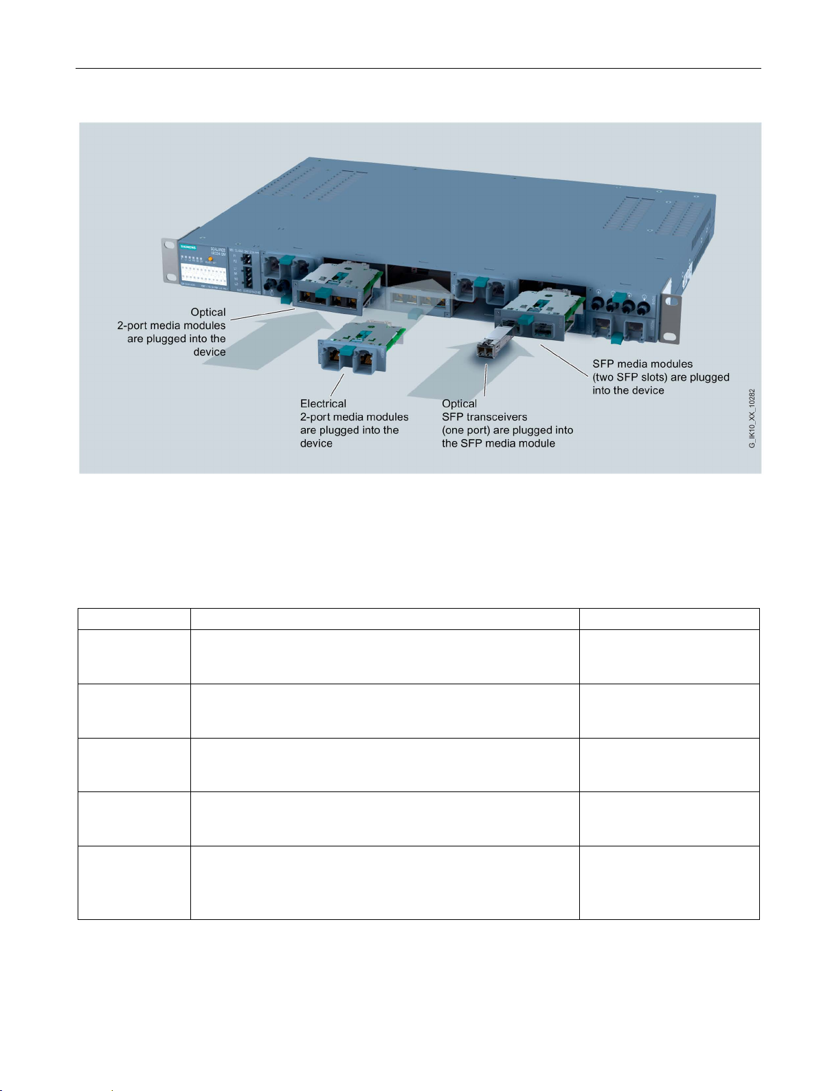
Image 2-1 Designs of the X-300 IE switches, example of plugging media modules into the media module slots
of the XR324-12M
7 x 10/100 Mbps RJ-45 ports electrical
1 x 10/100/1000 Mbps, RJ-45 ports electrical
4 x 10/100 Mbps RJ-45 ports electrical
2 x 1000 Mbps, SC ports optical, for glass FO cable (multimode), up
6 x 10/100 Mbps RJ-45 ports electrical
1 x 100 Mbps, SC port optical, for glass FO cable (single mode), up
to max. 26 km
3 x 1000 Mbps, SC ports optical, for glass FO cable (multimode), up
7 x 10/100 Mbps RJ-45 ports electrical
3 x 1000 Mbps, SC ports optical, for glass FO cable (single mode),
7 x 10/100 Mbps RJ-45 ports electrical
2 x 1000 Mbps, SC ports optical, for glass FO cable (multimode), up
6GK5 304-2BD00-2AA3
6GK5 306-1BF00-2AA3
6GK5 307-3BL00-2AA3
6GK5 307-3BL10-2AA3
6GK5 307-3BM00-2AA3
6GK5 307-3BM10-2AA3
6GK5 308-2FL00-2AA3
6GK5 308-2FL10-2AA3
SCALANCE X-300
Operating Instructions, 05/2016, A5E01113043-20
29
Page 30

Introduction
Device
Properties
Order number
X308-2LD
up to max. 10 km
X308-2LH
up to max. 40 km
X308-2LH+
up to max. 70 km
X310
7 x 10/100 Mbps RJ-45 ports electrical
6GK5 310-0FA10-2AA3
X310FE
6GK5 310-0BA10-2AA3
X320-1FE
max. 5 km
X320-3LD FE
to max. 26 km
2.2.4
Product group X-300M
Device
Properties
Order number
X308-2M
Diagnostics port at rear
X308-2M TS
Diagnostics port at rear
2.2 Product overview
1 x 10/100/1000 Mbps, RJ-45 ports electrical
7 x 10/100 Mbps RJ-45 ports electrical
2 x 1000 Mbps, SC ports optical, for glass FO cable (single mode),
1 x 10/100/1000 Mbps, RJ-45 ports electrical
7 x 10/100 Mbps RJ-45 ports electrical
2 x 1000 Mbps, SC ports optical, for glass FO cable (single mode),
1 x 10/100/1000 Mbps, RJ-45 ports electrical
7 x 10/100 Mbps RJ-45 ports electrical
2 x 1000 Mbps, SC ports optical, for glass FO cable (single mode),
3 x 10/100/1000 Mbps, RJ-45 ports electrical
10 x 10/100 Mbps RJ-45 ports electrical 6GK5 310-0BA00-2AA3
20 x 10/100 Mbps RJ-45 ports electrical
1 x 100 Mbps, SC port optical, for glass FO cable (multimode), up to
20 x 10/100 Mbps RJ-45 ports electrical
1 x 100 Mbps, SC port optical, for glass FO cable (multimode), up to
max. 5 km
2 x 100 Mbps, SC ports optical, for glass FO cable (single mode), up
6GK5 308-2FM00-2AA3
6GK5 308-2FM10-2AA3
6GK5 308-2FN00-2AA3
6GK5 308-2FN10-2AA3
6GK5 308-2FP00-2AA3
6GK5 308-2FP10-2AA3
6GK5 310-0FA00-2AA3
6GK5 320-1BD00-2AA3
6GK5 320-3BF00-2AA3
1 x 24 VDC
SCALANCE X-300
30 Operating Instructions, 05/2016, A5E01113043-20
4 x 10/100/1000 Mbps, RJ-45 ports electrical
2 x 100/1000 Mbps for 2-port media modules
LEDs, connector power supply and data cable outlet on
front
1 x 12 VDC, module varnished
4 x 10/100/1000 Mbps, RJ-45 ports electrical
2 x 100/1000 Mbps for 2-port media modules
LEDs, connector power supply and data cable outlet on
front
6GK5 308-2GG00-2AA2
6GK5 308-2GG00-2CA2
Page 31

Introduction
2.2.5
Product group XR-300M
Device
Properties
Order number
XR324-12M
Diagnostics port at rear
XR324-12M
Diagnostics port at rear
XR324-12M
connector power supply and data cable outlet at rear
XR324-12M
connector power supply and data cable outlet at rear
XR324-12M TS
Diagnostics port at rear
2.2.6
X-300EEC product group
Product / ports
Properties
Order number
X302-7EEC
1 x power supply unit 24 to 48 VDC
6GK5302-7GD00-1EA3
2 x power supply unit 24 to 48 VDC
6GK5302-7GD00-2EA3
1 x power supply unit 100 to 240 VAC / 60 to 250 VDC
6GK5302-7GD00-3EA3
Printed board varnished
2 x power supply unit 100 to 240 VAC / 60 to 250 VDC
6GK5302-7GD00-4EA3
Printed board varnished
X307-2EEC
1 x power supply unit 24 to 48 VDC
6GK5307-2FD00-1EA3
Printed board varnished
2 x power supply unit 24 to 48 VDC
6GK5307-2FD00-2EA3
Printed board varnished
2.2 Product overview
2 x 24 VDC
LEDs, connector power supply and data cable outlet on
front
1 x 100 to 240 VAC
LEDs, connector power supply and data cable outlet on
front
2 x 24 VDC
LEDs and diagnostics port on front
1 x 100 to 240 VAC
LEDs and diagnostics port on front
2 x 24 VDC, modules varnished
LEDs, connector power supply and data cable outlet on
front
6GK5 324-0GG00-1AR2
6GK5 324-0GG00-3AR2
6GK5 324-0GG00-1HR2
6GK5 324-0GG00-3HR2
6GK5 324-0GG00-1CR2
• 2 electrical ports
• 7 optical ports
• 7 electrical ports
• 2 optical ports
1 x power supply unit 24 to 48 VDC
Printed board varnished
2 x power supply unit 24 to 48 VDC
Printed board varnished
1 x power supply unit 100 to 240 VAC / 60 to 250 VDC
2 x power supply unit 100 to 240 VAC / 60 to 250 VDC
1 x power supply unit 24 to 48 VDC
2 x power supply unit 24 to 48 VDC
6GK5302-7GD00-1GA3
6GK5302-7GD00-2GA3
6GK5302-7GD00-3GA3
6GK5302-7GD00-4GA3
6GK5307-2FD00-1GA3
6GK5307-2FD00-2GA3
SCALANCE X-300
Operating Instructions, 05/2016, A5E01113043-20
31
Page 32

Introduction
Product / ports
Properties
Order number
1 x power supply unit 100 to 240 VAC / 60 to 250 VDC
6GK5307-2FD00-3EA3
2 x power supply unit 100 to 240 VAC / 60 to 250 VDC
6GK5307-2FD00-4EA3
Printed board varnished
* See naming key below
2.2.7
XR-300M EEC product group
Device
Properties
Order number
XR324-4M EEC
Connector power supply and diagnostics port at rear
Connector power supply and diagnostics port at rear
Connector power supply and diagnostics port at rear
Connector power supply and diagnostics port at rear
Data cable outlet and diagnostics port at rear
Data cable outlet and diagnostics port at rear
Data cable outlet and diagnostics port at rear
Data cable outlet and diagnostics port at rear
2.2 Product overview
1 x power supply unit 100 to 240 VAC / 60 to 250 VDC
Printed board varnished
2 x power supply unit 100 to 240 VAC / 60 to 250 VDC
1 x 24 to 48 VDC
LEDs, connector data cable outlet on front
2 x 24 to 48 VDC
LEDs, connector data cable outlet on front
1 x 100 to 240 VAC / 60 to 250 VDC
LEDs, connector data cable outlet on front
6GK5307-2FD00-3GA3
6GK5307-2FD00-4GA3
6GK5 324-4GG00-1ER2
6GK5 324-4GG00-2ER2
6GK5 324-4GG00-3ER2
2 x 100 to 240 VAC / 60 to 250 VDC
LEDs, connector data cable outlet on front
1 x 24 to 48 VDC
LEDs, connector power supply on front
2 x 24 to 48 VDC
LEDs, connector power supply on front
1 x 100 to 240 VAC / 60 to 250 VDC
LEDs, connector power supply on front
2 x 100 to 240 VAC / 60 to 250 VDC
LEDs, connector power supply on front
6GK5 324-4GG00-4ER2
6GK5 324-4GG00-1JR2
6GK5 324-4GG00-2JR2
6GK5 324-4GG00-3JR2
6GK5 324-4GG00-4JR2
SCALANCE X-300
32 Operating Instructions, 05/2016, A5E01113043-20
Page 33

Introduction
2.2.8
Product group X-300M PoE
Device:
Properties
Order number
X308-2M PoE
ules
Note
For more information on Power over Ethernet (PoE), refer to the Configuration Manual X
300/X
2.2.9
Product group XR-300M PoE
Device
Properties
Order number
XR324-4M PoE
Diagnostics port at rear.
Diagnostics port at rear.
connector power supply and data cable outlet at rear
XR324-4M PoE TS
Diagnostics port at rear.
Note
For more information on Power over Ethernet (PoE), refer to the Configuration Manual X
300/X
2.2 Product overview
4 x 10/100/1000 Mbps, RJ-45 ports elec-
trical
2 x 100/1000 Mbps for 2-port media mod-
6GK5 308-2QG00-2AA2
-
-400.
1 x 24 VDC, PoE
LEDs, connector power supply and data cable outlet on front
1 x 100 to 240 VAC, PoE
LEDs, connector power supply and data cable outlet on front
6GK5 324-4QG00-1AR2
6GK5 324-4QG00-3AR2
1 x 24 VDC, PoE
LEDs and diagnostics port at rear,
connector power supply and data cable outlet at rear
1 x 100 to 240 VAC, PoE
LEDs and diagnostics port on front,
1 x 24 VDC, PoE, module varnished
LEDs, connector power supply and data cable outlet on front
6GK5 324-4QG00-1HR2
6GK5 324-4QG00-3HR2
6GK5 324-4QG00-1CR2
-
-400.
SCALANCE X-300
Operating Instructions, 05/2016, A5E01113043-20
33
Page 34

Introduction
2.2.10
SFP transceiver
SFP transceiver
Type
Properties
Article number
1 x 100 Mbps, LC port optical for glass FO cable
(multimode), up to max. 5 km
(single mode) up to max. 26 km
(single mode) up to max. 26 km, varnished
(single mode) up to max. 70 km
(single mode) up to max. 200 km
cable (multimode), up to max. 750 m
cable (single mode) up to max. 10 km
cable (single mode) up to max. 10 km, varnished
cable (single mode) up to max. 40 km
cable (single mode) up to max. 120 km
Media modules
Note
The SFP media modules MM992
media module can be fitted with up to two pluggable transceivers.
The SFP media modules MM992
media module can be fitted with up to four pluggable transceivers.
2.2 Product overview
SFP991-1 *
SFP991-1 (C) * 1 x 100 Mbps, SC port optical, for glass FO
cable (multimode), up to max. 5 km, varnished
SFP991-1LD * 1 x 100 Mbps LC port optical for glass FO cable
SFP991-1LD (C) * 1 x 100 Mbps LC port optical for glass FO cable
SFP991-1LH+ * 1 x 100 Mbps LC port optical for glass FO cable
SFP991-1ELH200 * 1 x 100 Mbps LC port optical for glass FO cable
SFP992-1 1 x 1000 Mbps, LC port optical for glass FO
SFP992-1LD 1 x 1000 Mbps LC port optical for glass FO
SFP992-1LD (C) 1 x 1000 Mbps LC port optical for glass FO
6GK5 991-1AD00-8AA0
6GK5 991-1AD00-8FA0
6GK5 991-1AF00-8AA0
6GK5 991-1AF00-8FA0
6GK5 991-1AE00-8AA0
6GK5 991-1AE30-8AA0
6GK5 992-1AL00-8AA0
6GK5 992-1AM00-8AA0
6GK5 992-1AM00-8FA0
SFP992-1LH 1 x 1000 Mbps LC port optical for glass FO
SFP992-1LH+ 1 x 1000 Mbps LC port optical for glass FO
cable (single mode) up to max. 70 km
SFP992-1ELH 1 x 1000 Mbps LC port optical for glass FO
* Cannot be operated in SFP+ slots.
-2SFP may only be fitted with approved transceivers. The
-4SFP may only be fitted with approved transceivers. The
6GK5 992-1AN00-8AA0
6GK5 992-1AP00-8AA0
6GK5 992-1AQ00-8AA0
SCALANCE X-300
34 Operating Instructions, 05/2016, A5E01113043-20
Page 35

Introduction
Type
Properties
Article number
Labeling on the
device
8AA0
2.2.11
MM900 media modules
Note
Type designation and labeling of a media module differ
Example: The device with order number 6GK5 992
the labeling on the device is "9922AS".
The
numbers].
Note
Media modules for SFP transceivers
Only the media modules MM992
SFP transceivers. These SFP
Note
Supplement (C) in the type name
Media modules with the supplement (C) in the type name have varnished printed circuit
boards (conformal coating).
Media module
Properties
Order number
Labeling on the device
MM992-2CUC
9922GA
MM992-2CUC (C)
9922GA
MM992-2CU
9922SA
MM992-2M12 (C)
9922HA
MM992-2VD
9922VA
2.2 Product overview
MM992-2SFP 2 x 100 / 1000 Mbps, SFP media module 6GK5 992-2AS00-
MM992-4SFP 4 x 100 / 1000 Mbps, SFP media module 6GK5 992-4AS00-
8AA0
9922AS
9924AS
-2AS00-8AA0 is called "MM992-2SFP",
labeling on the devices is shown in bold face in the following table following the [order
-2SFP andMM992-2SFP (C) may be fitted with approved
media modules can be fitted with up to two SFPs.
2 x 10/100/1000 Mbps, RJ-45 ports electrical with securing collar 6GK5 992-2GA00-8AA0
2 x 10/100/1000 Mbps, RJ-45 ports electrical with securing collar, var-
nished
2 x 10/100/1000 Mbps, RJ-45 port electrical without securing collar 6GK5 992-2SA00-8AA0
2 x 10/100/1000 Mbps, GE M12 connector electrical, varnished 6GK5 992-2HA00-0AA0
2 x 10/100/1000 Mbps, RJ-45 ports electrical with securing collar, vari-
able distance
SCALANCE X-300
Operating Instructions, 05/2016, A5E01113043-20
6GK5 992-2GA00-8FA0
6GK5 992-2VA00-8AA0
35
Page 36

Introduction
Media module
Properties
Order number
Labeling on the device
MM992-2SFP
9922AS
MM992-2SFP (C)
9922AS
MM991-2
9912AB
MM991-2FM
9912AB
MM991-2LD
9912AC
MM991-2 (SC)
9912AD
MM991-2LD (SC)
9912AF
MM991-2LH+ (SC)
9912AE
MM991-2P
9912AH
MM992-2
9922AL
MM992-2 (C)
9922AL
MM992-2LD
9922AM
MM992-2LH
9922AN
MM992-2LH+
9922AP
MM992-2ELH
9922AQ
2.2 Product overview
2 x 100/1000 Mbps, SFP media module 6GK5 992-2AS00-8AA0
2 x 100/1000 Mbps, SFP media module, varnished 6GK5 992-2AS00-8FA0
2 x 100 Mbps, BFOC port optical, for glass FO cable (multimode), up to
max. 5 km
6GK5 991-2AB00-8AA0
2 x 100 Mbps, BFOC port optical, for glass FO cable (multimode) with
diagnostics up to max. 5 km
2 x 100 Mbps, BFOC port optical, for glass FO cable (single mode), up
to max. 26 km
2 x 100 Mbps, SC ports optical, for glass FO cable (multimode), up to
max. 5 km
2 x 100 Mbps, SC ports optical, for glass FO cable (single mode), up to
max. 26 km
2 x 100 Mbps, SC ports optical, for glass FO cable (single mode), up to
max. 70 km
2 x 100 Mbps SC RJ ports optical for Plastic Optical Fiber (POF) up to
max. 50 m or Polymer Cladded Fiber (PCF) up to max. 100 m
2 x 1000 Mbps, SC ports optical, for glass FO cable (multimode), up to
max. 750 m
2 x 1000 Mbps, SC ports optical, for glass FO cable (multimode), up to
max. 750 m, varnished
2 x 1000 Mbps, SC ports optical, for glass FO cable (single mode), up
to max. 10 km
2 x 1000 Mbps, SC ports optical, for glass FO cable (single mode), up
to max. 40 km
2 x 1000 Mbps, SC ports optical, for glass FO cable (single mode), up
to max. 70 km
6GK5 991-2AB01-8AA0
6GK5 991-2AC00-8AA0
6GK5 991-2AD00-8AA0
6GK5 991-2AF00-8AA0
6GK5 991-2AE00-8AA0
6GK5 991-2AH00-8AA0
6GK5 992-2AL00-8AA0
6GK5 992-2AL00-8FA0
6GK5 992-2AM00-8AA0
6GK5 992-2AN00-8AA0
6GK5 992-2AP00-8AA0
SCALANCE X-300
36 Operating Instructions, 05/2016, A5E01113043-20
2 x 1000 Mbps, SC ports optical, for glass FO cable (single mode), up
to max. 120 km
6GK5 992-2AQ00-8AA0
Page 37
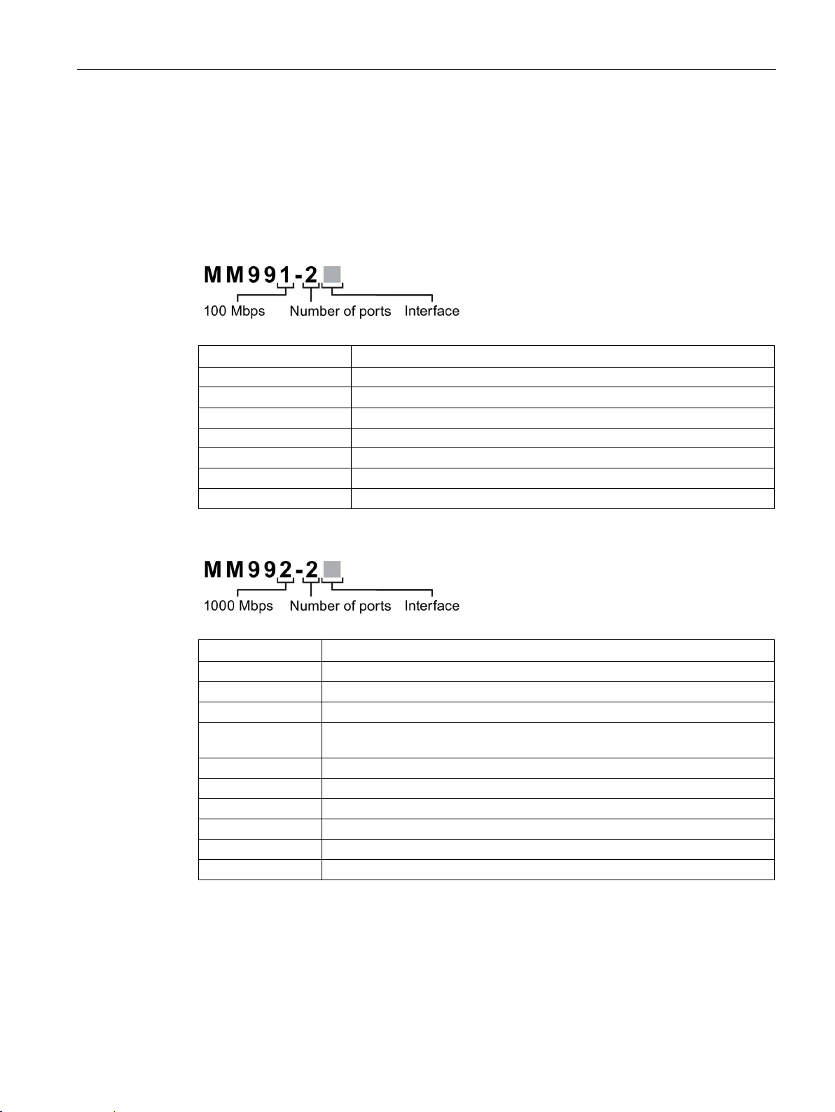
Introduction
Type key for the MM900 media modules
Interface
Property
[-]
BFOC port 100 Mbps multimode FO cable
LD
BFOC port 100 Mbps single mode FO cable
(SC)
SC port 100 Mbps multimode FO cable (up to max. 5 km)
LD (SC)
SC port 100 Mbps single mode FO cable (up to max. 26 km)
LH+ (SC)
SC port 100 Mbps single mode FO cable (up to max. 70 km)
FM
BFOC port 100 Mbps multimode FO cable with diagnostics
Interface
Property
CU
RJ-45 port electrical 10/100/1000 Mbps without securing collar
CUC
RJ-45 port electrical 10/100/1000 Mbps with securing collar
M12
M12 connection electrical 10/100/1000 Mbps
m)
[-]
SC port 1000 Mbps multimode FO cable (up to max. 750 m)
LD
SC port 1000 Mbps single mode FO cable (up to max. 10km)
LH
SC port 1000 Mbps single mode FO cable (up to max. 40 km)
LH+
SC port 1000 Mbps single mode FO cable (up to max. 70 km)
ELH
SC port 1000 Mbps single mode FO cable (up to max. 120 km)
SFP
SFP media module
2.2 Product overview
The type designation of an MM900 media module is made up of several parts that have the
following meaning:
P SC RJ port 100 Mbps POF or PCF
VD RJ-45 port electrical 10/100/1000 Mbps with securing collar (up to max. 1000
SCALANCE X-300
Operating Instructions, 05/2016, A5E01113043-20
37
Page 38

Introduction
2.2 Product overview
SCALANCE X-300
38 Operating Instructions, 05/2016, A5E01113043-20
Page 39
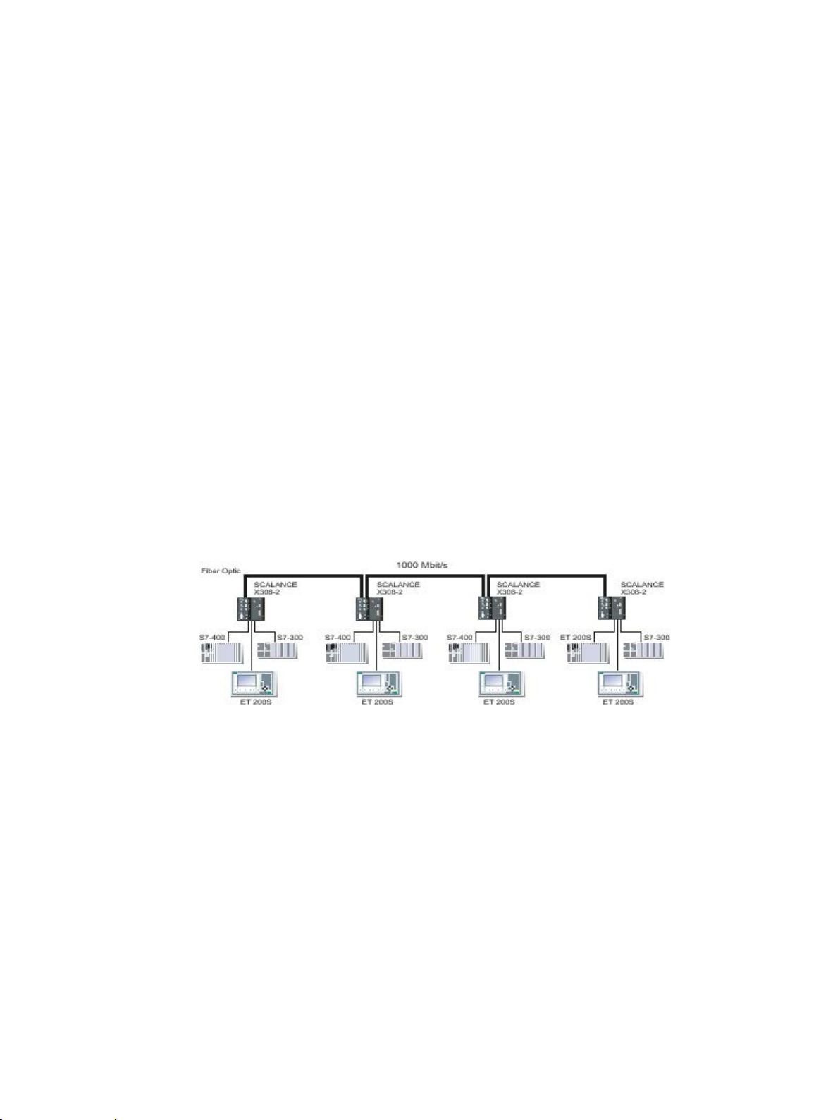
3
3.1
Linear structure
Functional description
Properties of the linear structure
Configuration example
3.2
Star/tree structure
Functional description
Linear structures can be created with the IE Switches X-300. The cascading depth and total
span of a network are limited only by the signal propagation times of the communication
connections.
Each IE Switch X-300 communicates over a TP or FO cable with a neighboring Ethernet
switch. Communication is possible over the optical or the electrical ports.
Sample configuration with SCALANCE X308-2, SIMATIC S7-300/400 and operator panel as
end devices.
Image 3-1 Linear structure (optical)
Star/tree structures can be created with the IE Switches X-300. The cascading depth and
total span of a network are limited only by the signal propagation times of the communication
connections.
SCALANCE X-300
Operating Instructions, 05/2016, A5E01113043-20
39
Page 40
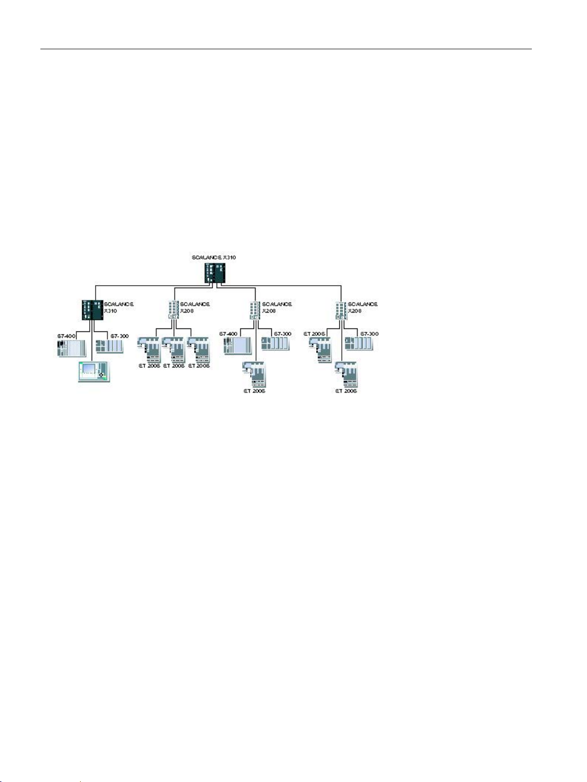
Network topologies
Properties of a star structure
Configuration example
3.3
Ring with redundancy manager
Ring with redundancy manager
Functional description
3.3 Ring with redundancy manager
Each IE Switch X-300 communicates over a TP or FO cable with a central switch with which
all other switches are also connected within a star structure. Communication is possible over
the optical or the electrical ports.
Sample electrical configurations with SCALANCE X310, SCALANCE X-200, SIMATIC S7300/400, SIMATIC ET 200, and operator panels as end devices.
Image 3-2 Star structure (electrical)
To increase availability, linear topologies of up to 100 switches can be closed to form a ring:
● Optical: SCALANCE X-400, SCALANCE X-300, SCALANCE X-200
● Electrical: SCALANCE X-400, SCALANCE X-300, SCALANCE X-200 or ESM
The two ends of the bus are closed to form a ring by a IE Switch X-300 operating as a
redundancy manager. Both the redundancy manager and the other IE switches (redundancy
clients) in the ring must be interconnected via their ring ports (see below).
SCALANCE X-300
40 Operating Instructions, 05/2016, A5E01113043-20
Page 41

Network topologies
Ring ports
Device
Factory setting for the ring ports
Electrical
Optical
X-304-2FE
Port 1 and port 2
X306-1LD FE
Port 2 and port 3
X307-3LD
Port 9 and port 10
X308-2LD
Port 9 and port 10
X308-2LH
Port 9 and port 10
X308-2LH+
Port 9 and port 10
X310
Port 9 and port 10
(no optical ports)
X310FE
Port 9 and port 10
(no optical ports)
X320-1FE
Port 1 and port 2
X320-3LD FE
Port 1 and port 2
X308-2M
Port 1 and port 2
X308-2M TS
Port 1 and port 2
X308-2M PoE
Port 1 and port 2
X302-7 EEC
Port 8 and port 9
X307-2 EEC
Port 8 and port 9
XR324-12M
Port 1.1 and port 1.2
3.3 Ring with redundancy manager
The redundancy manager function is enabled by the SELECT/SET button or by a setting in
the software. For more detailed information, refer to the configuration manual
"SCALANCE X-300 and SCALANCE X-400 Industrial Ethernet Switches".
In contrast to the ring ports of the redundancy clients, the ring ports of the redundancy
manager are disconnected when the network is operating problem-free. The IE Switch X-300
operating in the role of redundancy manager mode monitors the connected bus over its ring
ports and switches the ring ports through if there is an interruption on the connected bus; in
other words, it restores a functioning bus over this substitute path. Reconfiguration is
achieved within 0.3 s. As soon as the problem is eliminated, the original topology is restored;
in other words, the ring ports in the redundancy manager are disconnected from each other
again.
In a ring with media redundancy, only one device can operate as the redundancy manager.
An electrical ring with redundancy manager can be set up via the RJ-45 connectors that
allow attachment of electrical (twisted pair) connections (10, 100 and/or 1000 Mbps). The
SCALANCE X310FE is an exception to this. This device only allows attachment of electrical
(twisted-pair) connections at 10 or 100 Mbps.
The use of the IE Switch X-300 in an optical ring (1000 Mbps, with SCALANCE X-300EEC
100Mbps) with a redundancy manager is also possible with the exception of the devices
SCALANCE X310 and SCALANCE X310FE.
You can configure which ports take on the function of ring ports individually. The following
table shows the factory defaults for the ring ports.
X307-3 Port 9 and port 10
X308-2 Port 9 and port 10
SCALANCE X-300
Operating Instructions, 05/2016, A5E01113043-20
41
Page 42
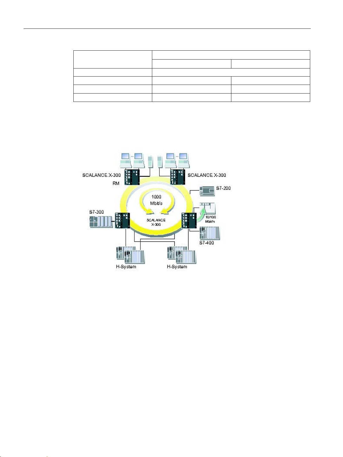
Network topologies
Device
Factory setting for the ring ports
Electrical
Optical
XR324-12M TS
Port 1.1 and port 1.2
XR324-4M EEC
Port 1 and port 2
XR324-4M PoE TS
Port 1 and port 2
Configuration example
3.3 Ring with redundancy manager
XR324-4M PoE Port 1 and port 2
Sample configurations with IE Switch X-300, SIMATIC S7-200/300/400, operator control and
monitoring system, H system, and PC as end devices.
SCALANCE X-300
42 Operating Instructions, 05/2016, A5E01113043-20
Image 3-3 Gigabit ring with redundancy manager (RM)
Page 43
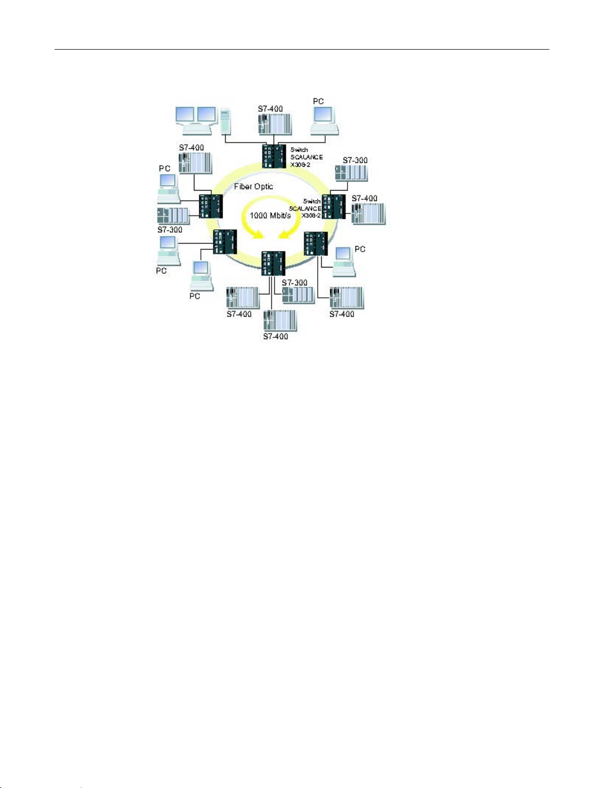
Network topologies
3.3 Ring with redundancy manager
Image 3-4 Ring with FO cable and redundancy manager
SCALANCE X-300
Operating Instructions, 05/2016, A5E01113043-20
43
Page 44
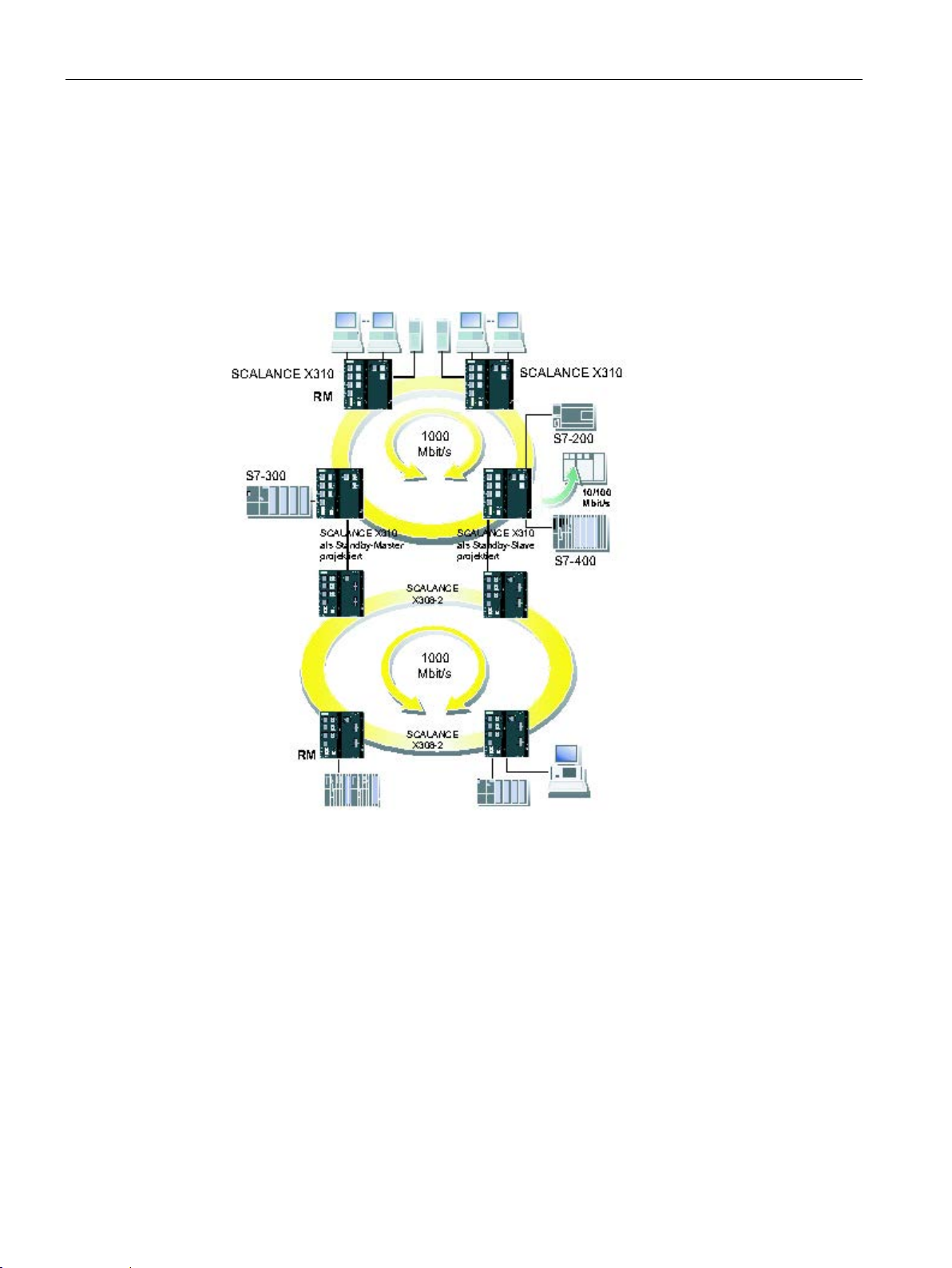
Network topologies
3.4
Redundant coupling of network segments
Redundant coupling of network segments
3.4 Redundant coupling of network segments
The example of redundant coupling of two network segments as shown here, for example
rings with a redundancy manager, can be implemented homogeneously with all SCALANCE
X300 variants.
Image 3-5 Redundant coupling of two subnets in mixed operation with SCALANCE X310 and
SCALANCE X308-2
In this case, network segments are rings with a redundancy manager (RM). The rings can
also be interrupted at one point (linear topology).
For a redundant link as shown in the figure, two IE Switches X-300 must be configured within
a network segment. This configuration is set in Web Based Management, Command Line
Interface or using SNMP access. For more detailed information, refer to the "Configuration
Manual SCALANCE X-300 and SCALANCE X-400 Industrial Ethernet Switches". The two
IE Switches X-300 connected in the configuration exchange data frames with each other to
SCALANCE X-300
44 Operating Instructions, 05/2016, A5E01113043-20
Page 45

Network topologies
Note
If IE
coupling of the gigabit
transmission rate.
3.4 Redundant coupling of network segments
synchronize their operating statuses (one device is master and the other slave). If there are
no problems, only the link from the master to the other network segment is active. If this link
fails (for example due to a link-down or a device failure), the slave activates its link as long
as the problem persists. Reconfiguration takes place within 0.3 s.
Switches X-300 or SCALANCE X408-2 devices are used exclusively for redundant
rings, the coupling links can also be designed with a gigabit
SCALANCE X-300
Operating Instructions, 05/2016, A5E01113043-20
45
Page 46

Network topologies
3.4 Redundant coupling of network segments
SCALANCE X-300
46 Operating Instructions, 05/2016, A5E01113043-20
Page 47

4
4.1
Compatibility of SCALANCE X-300
Compatibility list
Note
Modular devices (M)
The MM900 media modules and the SFP transceivers are used only in modular devices (M).
The following products and devices are compatible with IE Switches X-300:
● End devices:
All SIMATIC NET products with a TP interface can be connected to the ports of
IE Switches X-300.
● Network components with a bus (linear) or star structure:
ESM/OSM
OMC (TP cable max. 6 m long)
SCALANCE X005
SCALANCE X-100
SCALANCE XB000
SCALANCE XB000G
SCALANCE X-100 media converter
SCALANCE X-200
SCALANCE X-200IRT
SCALANCE XF200
SCALANCE XF204IRT
SCALANCE X-300
SCALANCE X-400
SCALANCE S-600
SCALANCE W-700
SCALANCE X-300
Operating Instructions, 05/2016, A5E01113043-20
47
Page 48

Description of the device
Note
All compatibility information assumes the correct use of the TP and FOC cables.
4.2 Product groups
● Network components in a ring structure with IE Switch X-300 as redundancy manager
– Electrical ring structure:
ESM/OSM
SCALANCE X-200
SCALANCE X-200IRT
SCALANCE XF200
SCALANCE XF204IRT
SCALANCE X-300 (it may be necessary to configure other ring ports)
SCALANCE X-400
– Optical ring structure:
SCALANCE X-400
SCALANCE X-300 (exceptions SCALANCE X310 and SCALANCE X310FE)
● Redundant coupling of networks
– In the network segment with the master-slave pair to be configured:
SCALANCE X-400
SCALANCE X-300
In the standby coupling also to SCALANCE X-200
– In the network segment to be coupled:
ESM/OSM
SCALANCE X-200
SCALANCE X-200IRT
SCALANCE XF200
SCALANCE XF204IRT
SCALANCE X-300
SCALANCE X-400
SCALANCE X-300
48 Operating Instructions, 05/2016, A5E01113043-20
Page 49
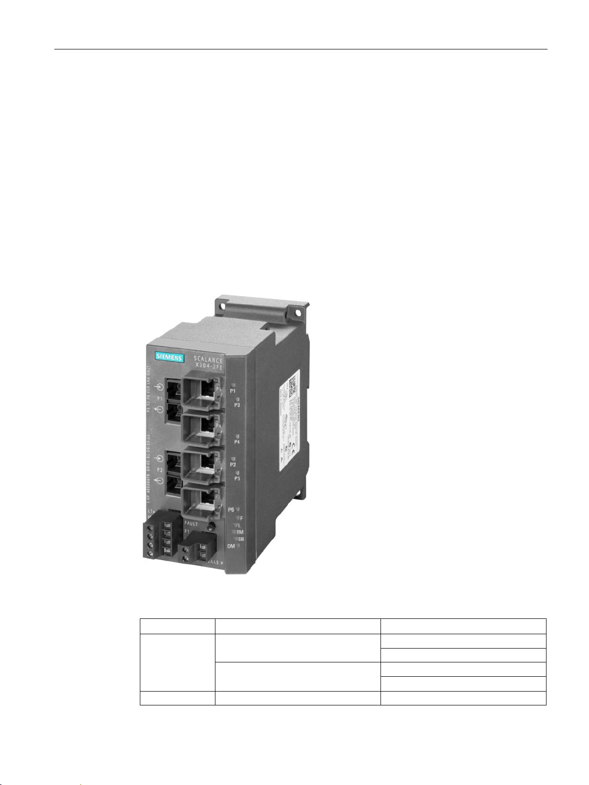
Description of the device
4.2
Product groups
4.2.1
X-300 product group
4.2.1.1
SCALANCE X304-2FE product characteristics
Possible attachments
Column
1
2
Port number
P3
P4
P5
Connection type
Optical: Fast Ethernet
Electrical: Fast Ethernet
4.2 Product groups
The SCALANCE X304-2FE provides the following options for the connection of end devices
or other network segments:
● 4 RJ-45 jacks
● 2 FO ports (for multimode fiber)
SCALANCE X-300
Operating Instructions, 05/2016, A5E01113043-20
Image 4-1 X304-2FE
P1
P2
P6
49
Page 50
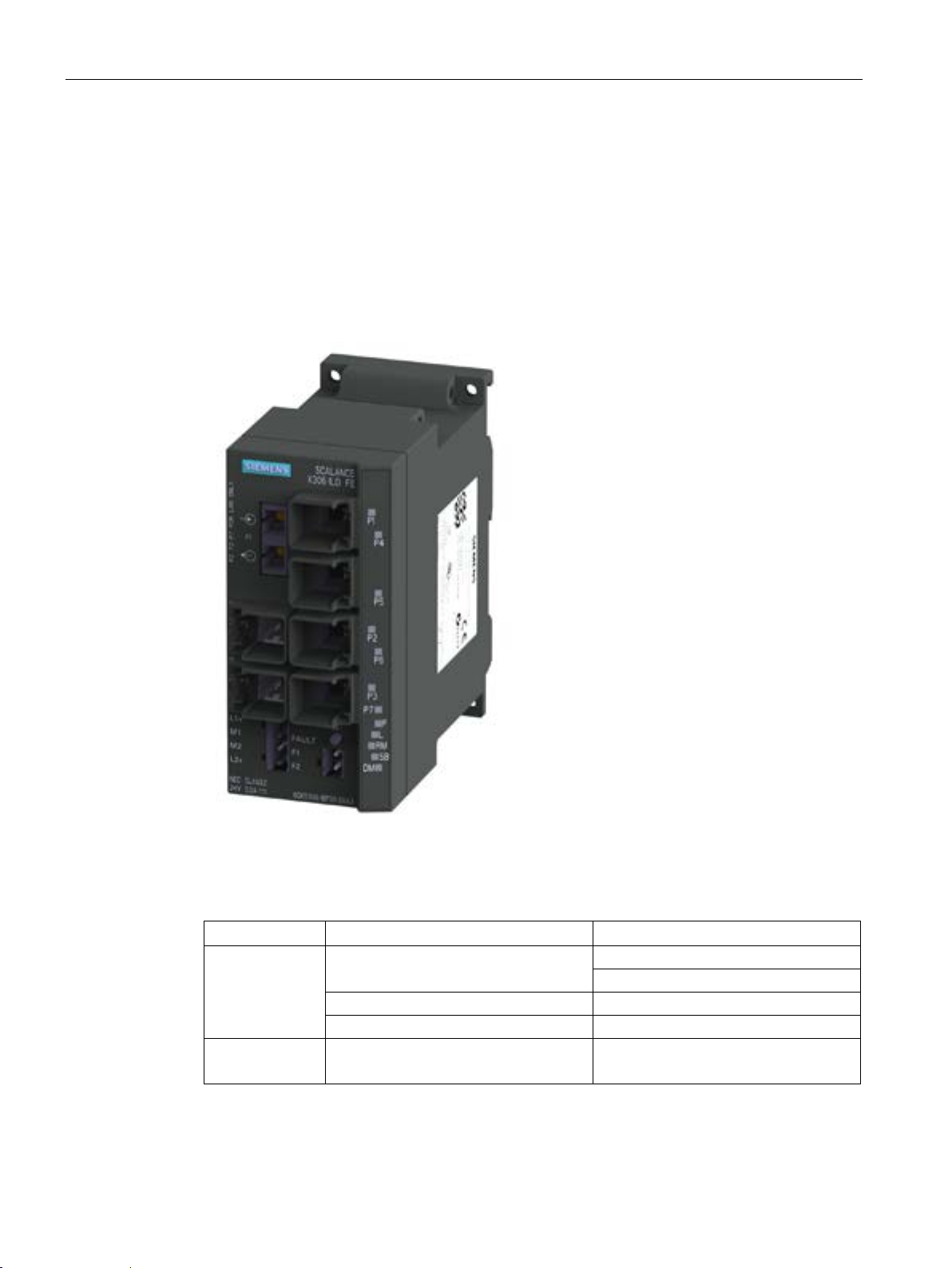
Description of the device
4.2.1.2
SCALANCE X306-1LD FE product characteristics
Possible attachments
Column
1
2
Port number
P4
P5
P2
P6
P3
P7
Connection type
*) Optical: Fast Ethernet
4.2 Product groups
The SCALANCE X306-1LD FE provides the following options for the connection of end
devices or other network segments:
● 6 RJ-45 jacks
● 1 FO port (for single mode fiber)
SCALANCE X-300
50 Operating Instructions, 05/2016, A5E01113043-20
Image 4-2 SCALANCE X306-1LD FE
P1 *)
Electrical: Fast Ethernet
Electrical: Fast Ethernet
Page 51
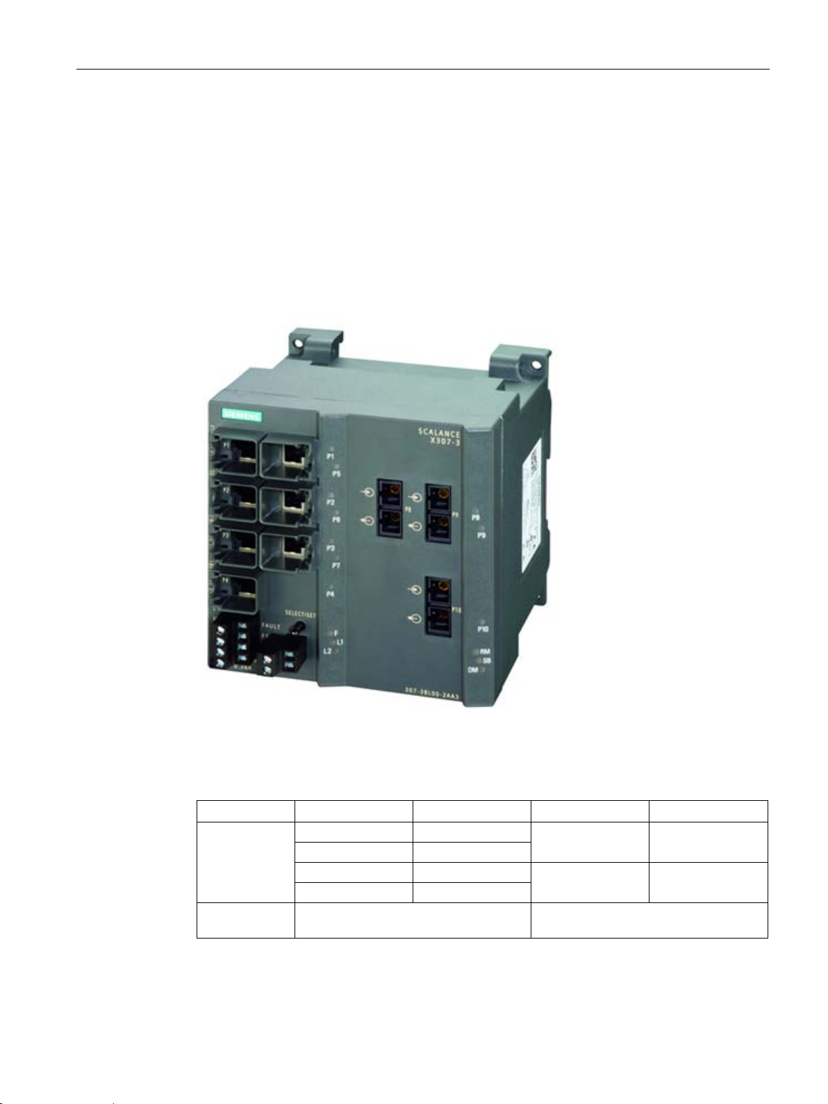
Description of the device
4.2.1.3
SCALANCE X307-3 product characteristics
Possible attachments
Column
1 2 3
4
Port number
P1
P5
P2
P6
P3
P7
P4
-
Connection
type
4.2 Product groups
The SCALANCE X307-3 provides the following options for the connection of end devices or
other network segments:
● 7 RJ-45 jacks
● 3 FO ports (for multimode fiber)
Image 4-3 SCALANCE X307-3
Electrical: Fast Ethernet Optical: Gigabit Ethernet
SCALANCE X-300
Operating Instructions, 05/2016, A5E01113043-20
P8 P9
- P10
51
Page 52
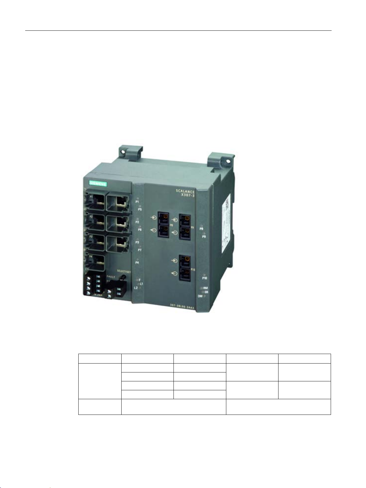
Description of the device
4.2.1.4
SCALANCE X307-3LD product characteristics
Possible attachments
Column
1 2 3
4
Port number
P1
P5
P2
P6
P3
P7
P4
-
Connection
type
4.2 Product groups
The SCALANCE X306-3LD provides the following options for the connection of end devices
or other network segments:
● 7 RJ-45 jacks
● 3 FO ports (for single mode fiber)
Image 4-4 SCALANCE X307-3LD
SCALANCE X-300
52 Operating Instructions, 05/2016, A5E01113043-20
Electrical: Fast Ethernet Optical: Gigabit Ethernet
P8 P9
- P10
Page 53
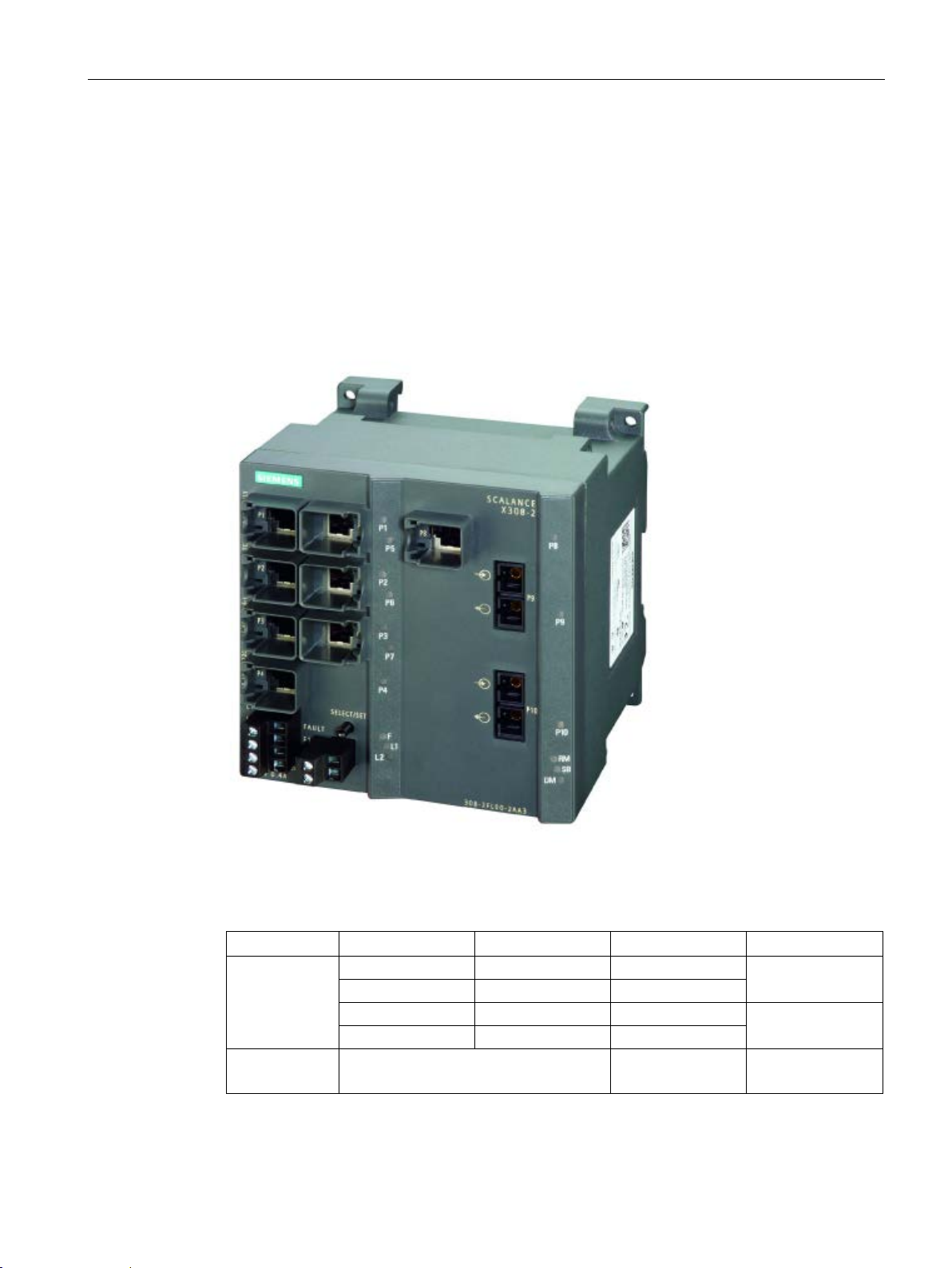
Description of the device
4.2.1.5
SCALANCE X308-2LH product characteristics
Possible attachments
Column
1 2 3
4
Port number
P1
P5
P8
P2
P6
-
P3
P7
-
P4 - -
Connection
type
Gigabit Ethernet
Gigabit Ethernet
4.2 Product groups
The SCALANCE X308-2LH provides the following options for the connection of end devices
or other network segments:
● 8 RJ-45 jacks
● 2 FO ports (for single mode fiber)
Image 4-5 SCALANCE X308-2LH
SCALANCE X-300
Operating Instructions, 05/2016, A5E01113043-20
Electrical: Fast Ethernet
Electrical:
P9
P10
Optical:
53
Page 54
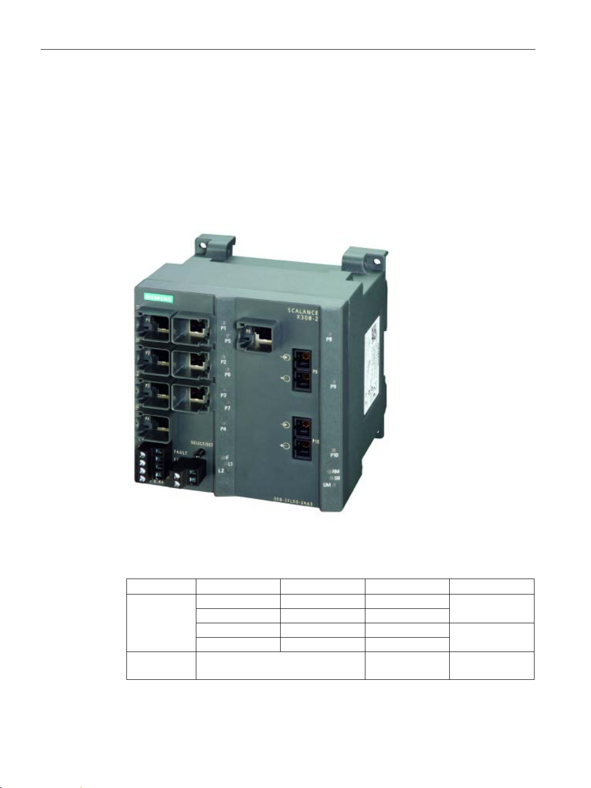
Description of the device
4.2.1.6
SCALANCE X308-2LH+ product characteristics
Possible attachments
Column
1 2 3
4
Port number
P1
P5
P8
P2
P6
-
P3
P7
-
P4 - -
Connection
type
Gigabit Ethernet
Gigabit Ethernet
4.2 Product groups
The SCALANCE 308-2LH+ provides the following options for the connection of end devices
or other network segments:
● 8 RJ-45 jacks
● 2 FO ports (for single mode fiber)
Image 4-6 SCALANCE X308-2LH+
SCALANCE X-300
54 Operating Instructions, 05/2016, A5E01113043-20
Electrical: Fast Ethernet
Electrical:
P9
P10
Optical:
Page 55
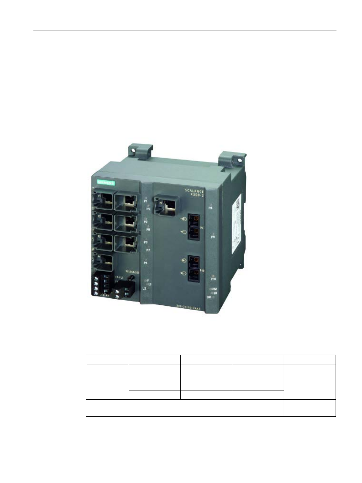
Description of the device
4.2.1.7
SCALANCE X308-2 product characteristics
Possible attachments
Column
1 2 3
4
Port number
P1
P5
P8
P2
P6
-
P3
P7
-
P4 - -
Connection
type
Gigabit Ethernet
Gigabit Ethernet
4.2 Product groups
The SCALANCE X308-2 provides the following options for the connection of end devices or
other network segments:
● 8 RJ-45 jacks
● 2 FO ports (for multimode fiber)
Image 4-7 SCALANCE X308-2
SCALANCE X-300
Operating Instructions, 05/2016, A5E01113043-20
Electrical: Fast Ethernet
Electrical:
P9
P10
Optical:
55
Page 56
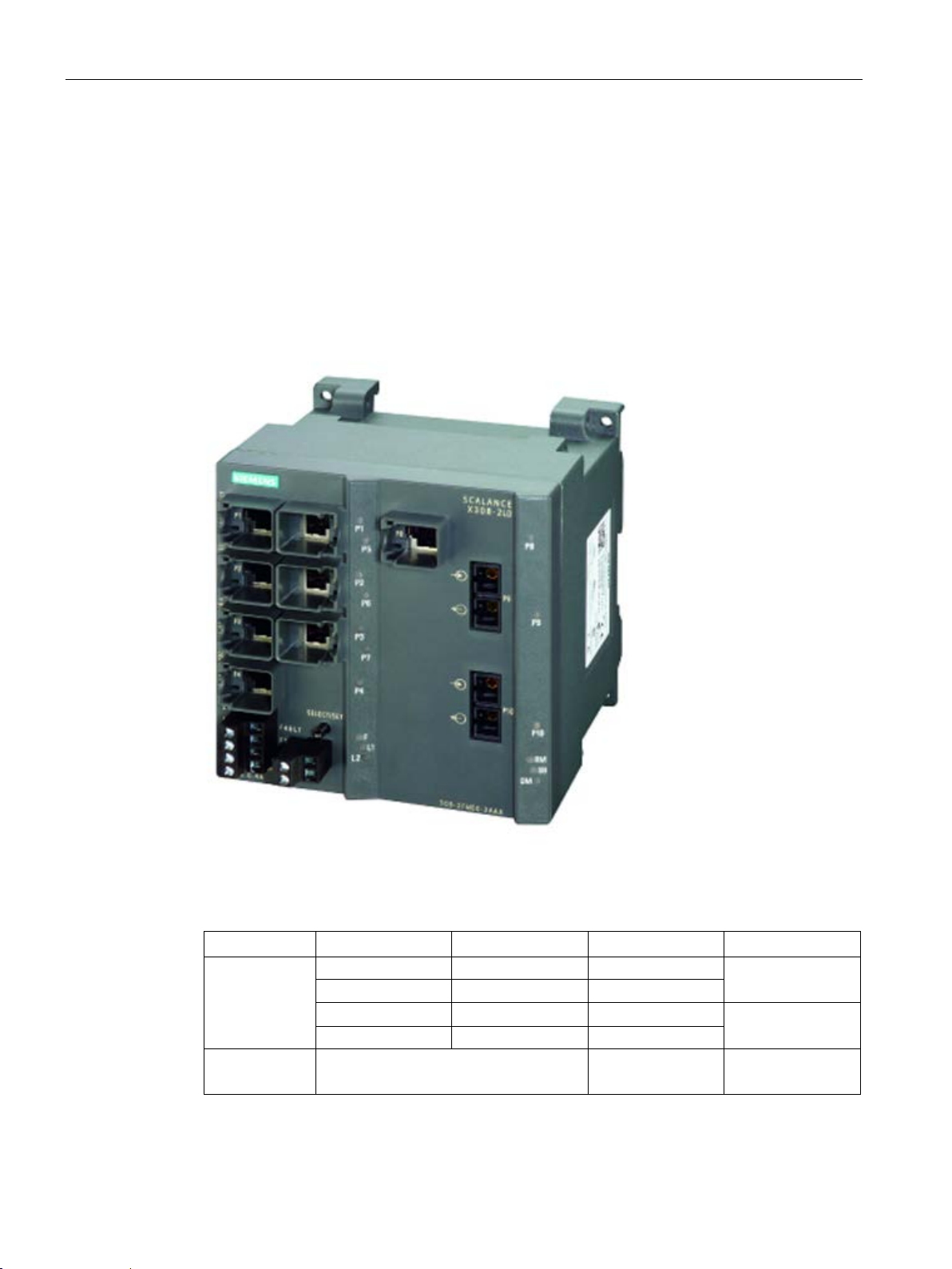
Description of the device
4.2.1.8
SCALANCE X308-2LD product characteristics
Possible attachments
Column
1 2 3
4
Port number
P1
P5
P8
P2
P6
-
P4 - -
Connection
type
Gigabit Ethernet
Gigabit Ethernet
4.2 Product groups
The SCALANCE X308-2LD provides the following options for the connection of end devices
or other network segments:
● 8 RJ-45 jacks
● 2 FO ports (for single mode fiber)
Image 4-8 SCALANCE X308-2LD
SCALANCE X-300
56 Operating Instructions, 05/2016, A5E01113043-20
P3 P7 - P10
Electrical: Fast Ethernet
Electrical:
P9
Optical:
Page 57
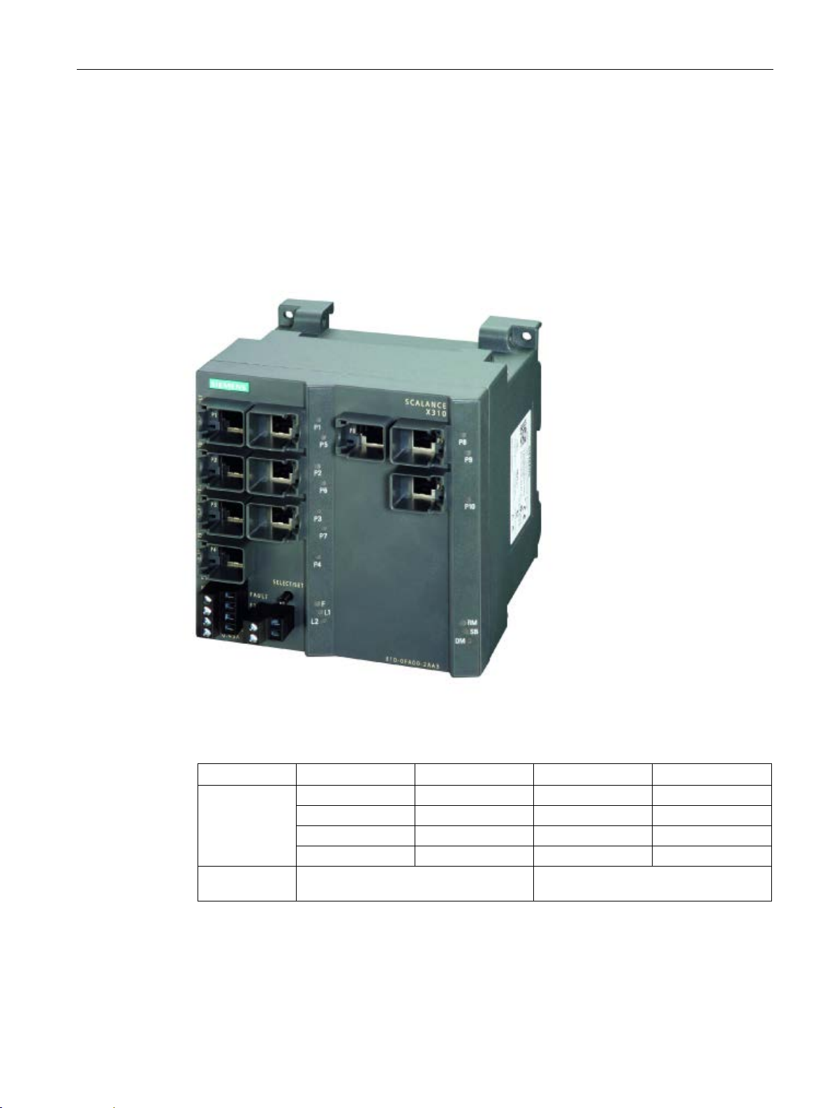
Description of the device
4.2.1.9
SCALANCE X310 product characteristics
Possible attachments
Column
1 2 3
4
Port number
P1
P5
P8
P9
P2
P6 - P10
P3
P7 - -
P4 - -
-
Connection
type
4.2 Product groups
The SCALANCE X310 provides the following options for the connection of end devices or
other network segments:
● 10 RJ-45 jacks
Image 4-9 SCALANCE X310
Electrical: Fast Ethernet Electrical: Gigabit Ethernet
SCALANCE X-300
Operating Instructions, 05/2016, A5E01113043-20
57
Page 58
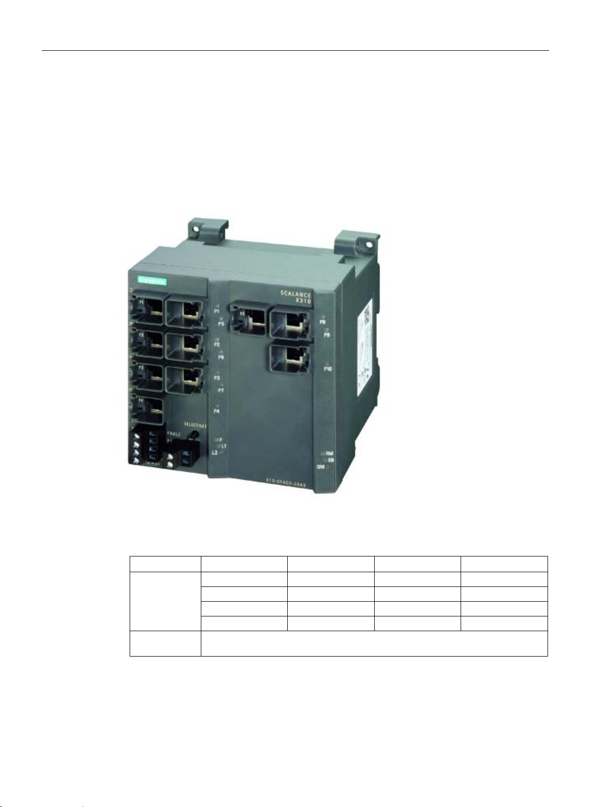
Description of the device
4.2.1.10
SCALANCE X310FE product characteristics
Possible attachments
Column
1 2 3
4
Port number
P1
P5
P8
P9
P2
P6 - P10
P3
P7 - -
P4 - -
-
Connection
type
4.2 Product groups
The SCALANCE X310FE provides the following options for the connection of end devices or
other network segments:
● 10 RJ-45 jacks
Image 4-10 SCALANCE X310FE
SCALANCE X-300
58 Operating Instructions, 05/2016, A5E01113043-20
Electrical: Fast Ethernet
Page 59
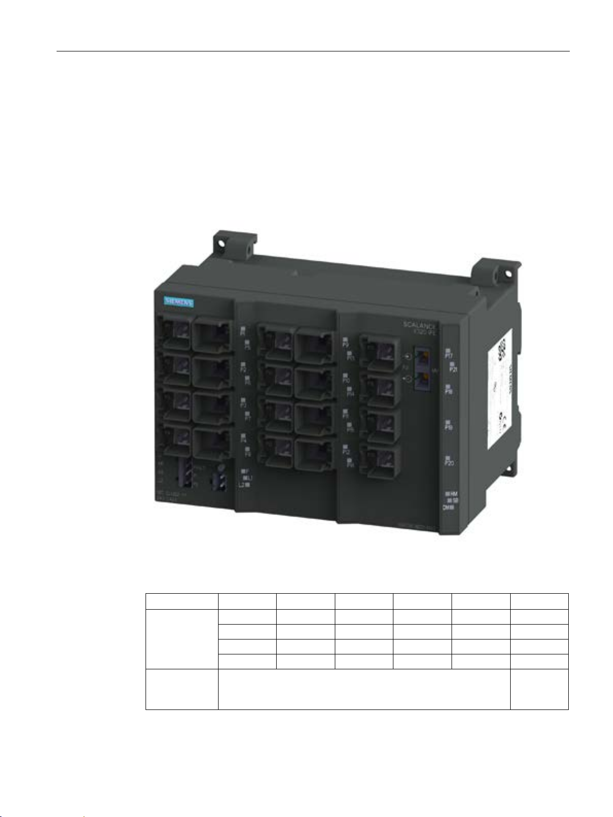
Description of the device
4.2.1.11
SCALANCE X320-1FE product characteristics
Possible attachments
Column
1 2 3 4 5
6
Port number
P1
P5
P9
P13
P17
P21
P2
P6
P10
P14
P18
-
P3
P7
P11
P15
P19
-
P4
P8
P12
P16
P12
-
Connection
type
net
4.2 Product groups
The SCALANCE X320-1 FE provides the following options for the connection of end devices
or other network segments:
● 20 RJ-45 jacks
● 1 FO port (for multimode fiber)
Image 4-11 SCALANCE X320-1 FE
Electrical: Fast Ethernet Optical:
SCALANCE X-300
Operating Instructions, 05/2016, A5E01113043-20
Fast Ether-
59
Page 60
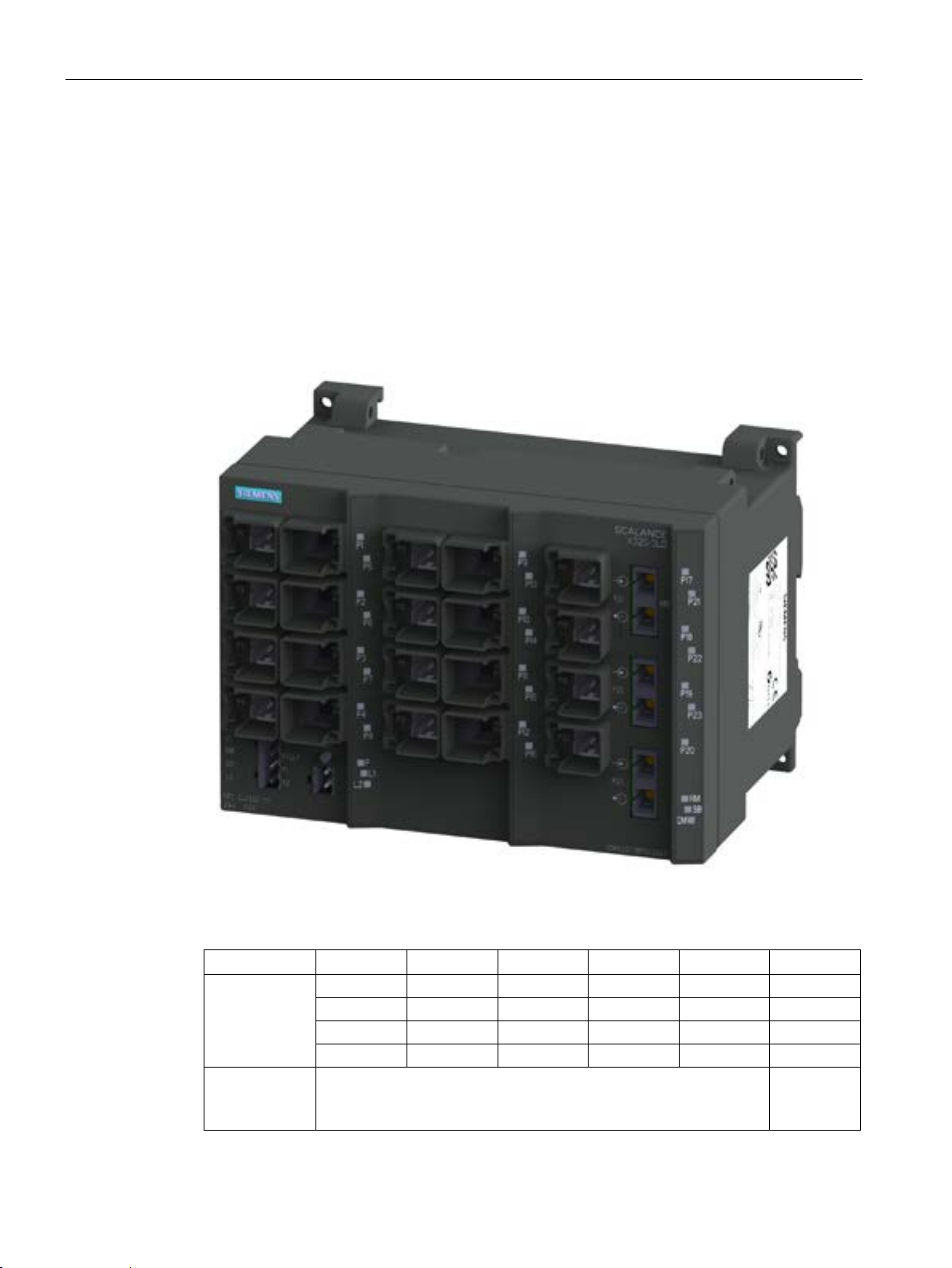
Description of the device
4.2.1.12
SCALANCE X320-3LD FE product characteristics
Possible attachments
Column
1 2 3 4 5
6
Port number
P1
P5
P9
P13
P17
P21
P2
P6
P10
P14
P18
P22
P3
P7
P11
P15
P19
P23
P4
P8
P12
P16
P20
-
Connection
type
net
4.2 Product groups
The SCALANCE X320-3LD FE provides the following options for the connection of end
devices or other network segments:
● 20 RJ-45 jacks
● 1 FO port (for multimode fiber)
● 2 FO ports (for single mode fiber)
SCALANCE X-300
60 Operating Instructions, 05/2016, A5E01113043-20
Image 4-12 SCALANCE X320-3LD FE
Electrical: Fast Ethernet Optical:
Fast Ether-
Page 61
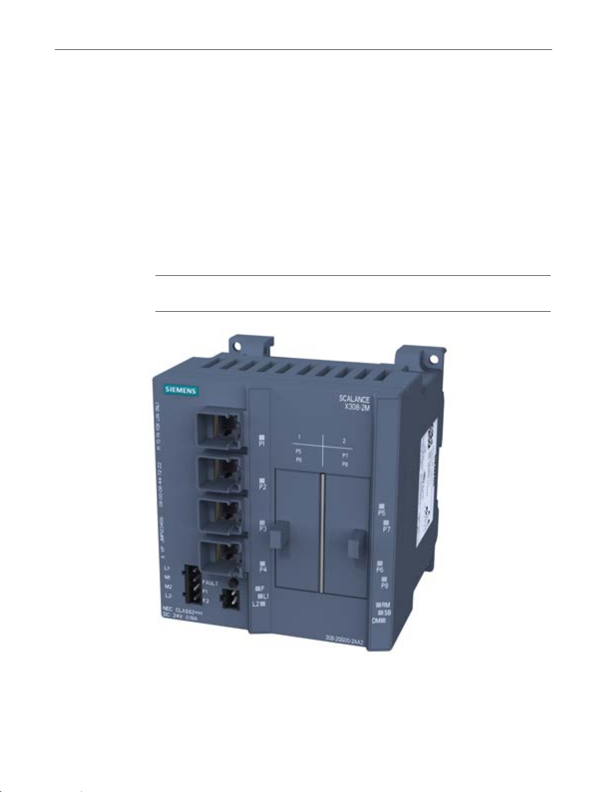
Description of the device
4.2.2
Product group X-300M
Possible attachments
4 fixed ports in the base device:
4 modular ports via module slots:
Note
When shipped, the slots for the media modules have a dummy cover fitted.
4.2 Product groups
The SCALANCE X308-2M and X308-2M TS are partly modular devices and each has 8
ports.
●
4 electrical RJ-45 jacks (with securing collars) for connection of end devices or other
network segments.
●
Two media modules (optical or electrical as required) can be combined using slots (S1S2) depending on the application. End devices and other network segments are
connected according to the media modules being used.
Image 4-13 SCALANCE X308-2M with dummy covers
SCALANCE X-300
Operating Instructions, 05/2016, A5E01113043-20
61
Page 62
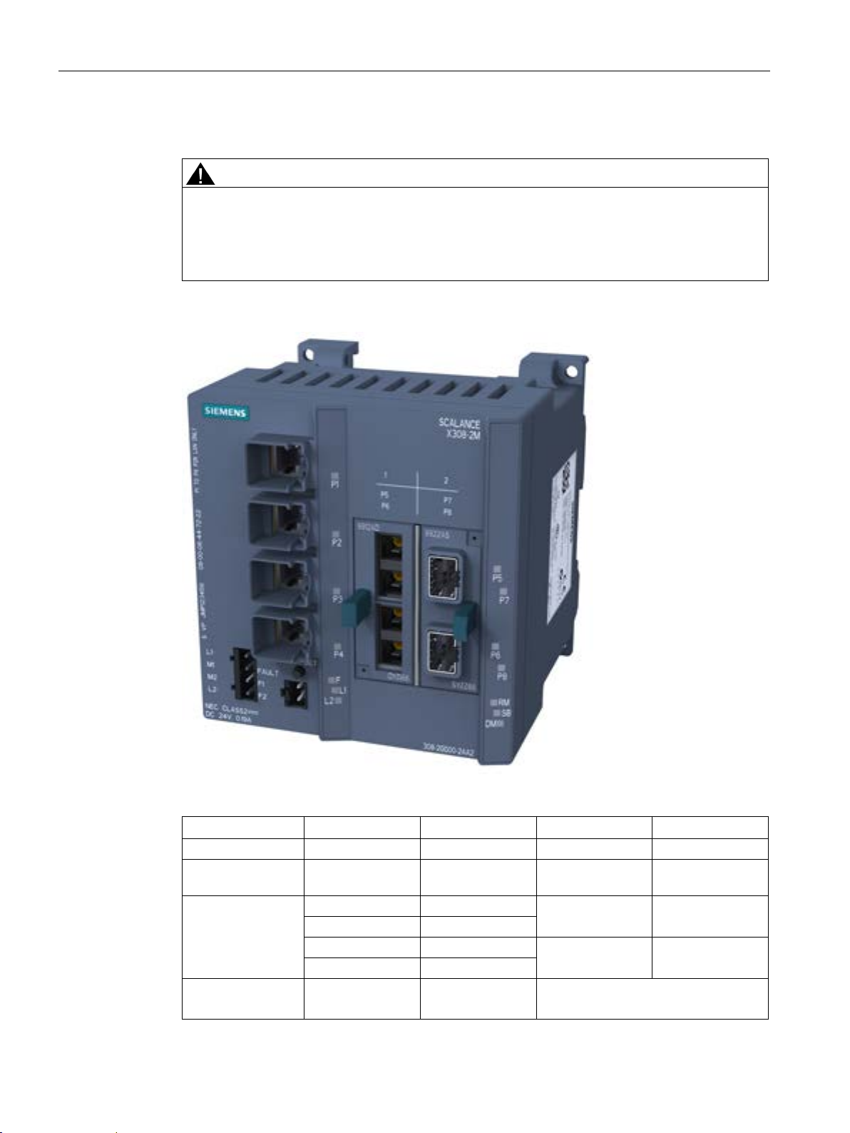
Description of the device
Possible attachments (example)
CAUTION
Use only approved media modules in the module slots
Example of connections
Column
1 2 3
4
Slot number
- - S1
S2
Media
modules used
Port number
-
P1
-
P2
-
P3
-
P4
Connection type
Gigabit Ethernet
4.2 Product groups
The connection of end devices or other network segments does not depend on the module
slot, but rather on the selected media module.
Refer to the section Media module installation in slot.
Image 4-14 SCALANCE X308-2M with MM992-2 and MM991-2
MM992-2 MM991-2
- Optical:
SCALANCE X-300
62 Operating Instructions, 05/2016, A5E01113043-20
P5 P7
P6 P8
Connection type depending on module
used
Page 63
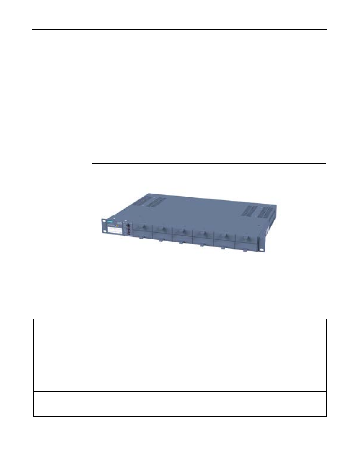
Description of the device
4.2.3
Product group XR-300M
Possible attachments
0 fixed ports on the base device
24 modular ports via module slots:
Note
When shipped, the slots for the media modules have a dummy cover fitted.
Overview of the SCALANCE XR324-12M product
Device
Variant
Order number
XR324-12M
Diagnostics port at rear
XR324-12M
Diagnostics port at rear
XR324-12M
connector power supply and data cable outlet at rear
4.2 Product groups
The SCALANCE XR324-12M is a fully modular device and has 24 ports.
●
●
12 media modules (optical or electrical as required) can be combined using slots (S1S12) depending on the application. End devices and other network segments are
connected according to the modules being used.
Image 4-15 SCALANCE XR324-12M with blind covers
2 x 24 VDC
LEDs, connector power supply and data cable outlet on
front
1 x 100 to 240 VAC
LEDs, connector power supply and data cable outlet on
front
2 x 24 VDC
LEDs and diagnostics port on front
SCALANCE X-300
Operating Instructions, 05/2016, A5E01113043-20
6GK5 324-0GG00-1AR2
6GK5 324-0GG00-3AR2
6GK5 324-0GG00-1HR2
63
Page 64
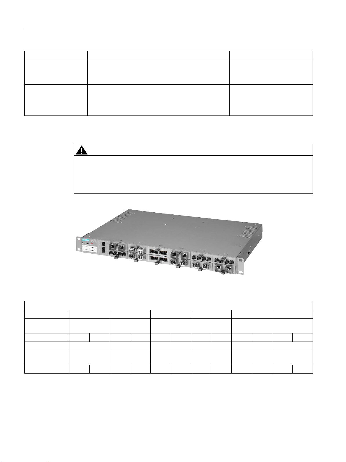
Description of the device
Device
Variant
Order number
XR324-12M
connector power supply and data cable outlet at rear
XR324-12M TS
Diagnostics port at rear
Example of a configuration
CAUTION
Use only approved media modules in the module slots
Slot number
S1
S2
S3
S4
S5
S6
Media
modules used
Port number
P1
P2
P1
P2
P1
P2
P1
P2
P1
P2
P1
P2
Slot number
S7
S8
S9
S10
S11
S12
Media
modules used
Port number
P1
P2
P1
P2
P1
P2
P1
P2
P1
P2
P1
P2
4.2 Product groups
1 x 100 to 240 VAC,
LEDs and diagnostics port on front
2 x 24 VDC, modules varnished
LEDs, connector power supply and data cable outlet on
front
The connection of end devices or other network segments does not depend on the module
slot, but rather on the selected media module.
Refer to the section Media module installation in slot.
6GK5 324-0GG00-3HR2
6GK5 324-0GG00-1CR2
Image 4-16 SCALANCE XR324-12M with MM900
MM992-2CUC MM992-2CUC MM992-2CUC MM991-2 (SC) MM991-2 (SC) MM991-2 (SC)
MM992-2CUC MM992-2CUC MM992-2CUC MM991-2 MM991-2 MM991-2
SCALANCE X-300
64 Operating Instructions, 05/2016, A5E01113043-20
Page 65

Description of the device
4.2.4
X-300EEC product group
4.2.4.1
Characteristics of the X-300EEC product group
Variants
SCALANCE X302-7EEC
SCALANCE X307-2EEC
Device versions
Power supply
Power supply unit
Printed board
4.2 Product groups
The SCALANCE X-300EEC is a 19"/2 device with 9 ports for the connection of end devices
or other network segments. There are 2 device types with the following ports:
●
– 2 x RJ-45 jacks
– 7 x FO ports for multimode fiber, LC connector
●
– 7 x RJ-45 jacks
– 2 x FO ports for multimode fiber, LC connector
The X-300EEC is available in the following alternative versions:
●
– Power supply unit 24 to 48 VDC
– Multirange power supply unit 100 to 240 VAC / 60 to 250 VDC
●
– Single
– Redundant
●
– Varnished (suitable for aggressive environments)
– Unvarnished
This combination of versions results in the product variants listed in section X-300EEC
product group (Page 31).
SCALANCE X-300
Operating Instructions, 05/2016, A5E01113043-20
65
Page 66
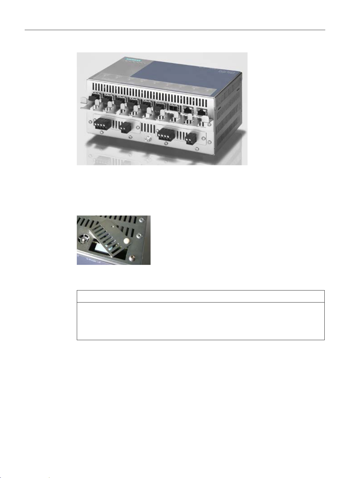
Description of the device
Replacing the C-PLUG
NOTICE
4.2 Product groups
Image 4-17 SCALANCE X302-7EEC (from below) with protective bracket and LC connector
In the X-300EEC devices, the slot for the C-PLUG is on the top on the housing.
Image 4-18 C-PLUG of the X-300EEC
The C-PLUG may only be removed or inserted when the power supply to the device is
turned off.
In a device with a varnished printed circuit board, you may only use a C-PLUG with a
varnished board.
To remove the C-PLUG, open the slider and close it again after inserting the C-PLUG.
SCALANCE X-300
66 Operating Instructions, 05/2016, A5E01113043-20
Page 67

Description of the device
Terminal block for signaling contact and power supply
RJ-45 interface
LEDs of the X-300EEC
4.2 Product groups
The terminal block of the X-300EEC for connecting the signaling contact and power supply
has the following terminals:
● F1, F2: Signaling contact
The 2 signaling contacts on the device version with a redundant power supply are
energized in parallel.
● L1, M1: Power supply 1
● L2, M2: Power supply 2 (redundant version)
The power supply units for the power supply are available in the following versions:
– 24 to 48 VDC
– As multirange power supply unit 100 to 240 VAC / 60 to 250 VDC
The RJ-45 ports of the IE Switch X-300EEC are fitted with a securing bracket instead of a
securing collar.
To increase mechanical stability, secure the IE FC RJ-45 PLUGs to this securing bracket
with a cable binder.
You will find the meaning of the individual LEDs in the section "LED display (Page 151)".
SCALANCE X-300
Operating Instructions, 05/2016, A5E01113043-20
67
Page 68
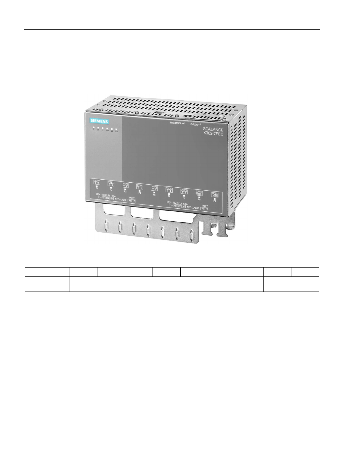
Description of the device
Ports of the X302-7EEC
Port number
P1
P2
P3
P4
P5
P6
P7
P8
P9
Connection type
Ethernet
4.2 Product groups
The SCALANCE X302-7EEC has the following ports:
● 2 electrical gigabit ports (P8 to P9)
● 7 optical Fast Ethernet ports (P1 to P7)
Image 4-19 SCALANCE X302-7EEC
Optical: Fast Ethernet Electrical: Gigabit
SCALANCE X-300
68 Operating Instructions, 05/2016, A5E01113043-20
Page 69
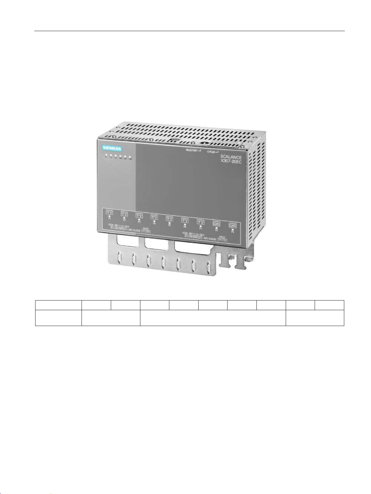
Description of the device
Ports of the X307-2EEC
Port number
P1
P2
P3
P4
P5
P6
P7
P8
P9
Connection type
net
Ethernet
4.2 Product groups
The SCALANCE X307-2EEC has the following ports:
● 7 electrical ports (P3 to P9)
– 5 Fast Ethernet ports (P3 to P7)
– 2 gigabit ports (P8, P9)
● 2 optical Fast Ethernet ports (P1, P2)
Image 4-20 SCALANCE X307-2EEC
Optical: Fast Ether-
Electrical: Fast Ethernet Electrical: Gigabit
SCALANCE X-300
Operating Instructions, 05/2016, A5E01113043-20
69
Page 70

Description of the device
4.2.5
XR-300M EEC product group
4.2.5.1
Product characteristics of the SCALANCE XR324-4M EEC
Connection options with the SCALANCE XR324-4M EEC
16 fixed ports in the base device:
8 modular ports via module slots:
CAUTION
Use only approved media modules
Slot number
S1
S2
Port number
P1
P2
P3
P4
P5
P6
P7
P8
P1
P2
P1
P2
Slot number
S3
S4
Port number
P9
P10
P11
P12
P13
P14
P15
P16
P1
P2
P1
P2
4.2 Product groups
The SCALANCE XR324-4M EEC is a partially modular device and has 24 ports.
●
16 RJ-45 jacks for connection of end devices or other network segments.
●
4 modules can be combined using slots (S1-S4) depending on the application. End
devices and other network segments are connected according to the modules being
used.
Image 4-21 XR324-4M EEC
If you use media modules that are not approved by Siemens AG, there is no guarantee
that the device will function according to the specification.
If you use unapproved media modules, this can lead to the following problems:
• Damage to the device
• Loss of the approvals
• Violation of the EMC regulations
Use only approved media modules.
SCALANCE X-300
70 Operating Instructions, 05/2016, A5E01113043-20
Page 71
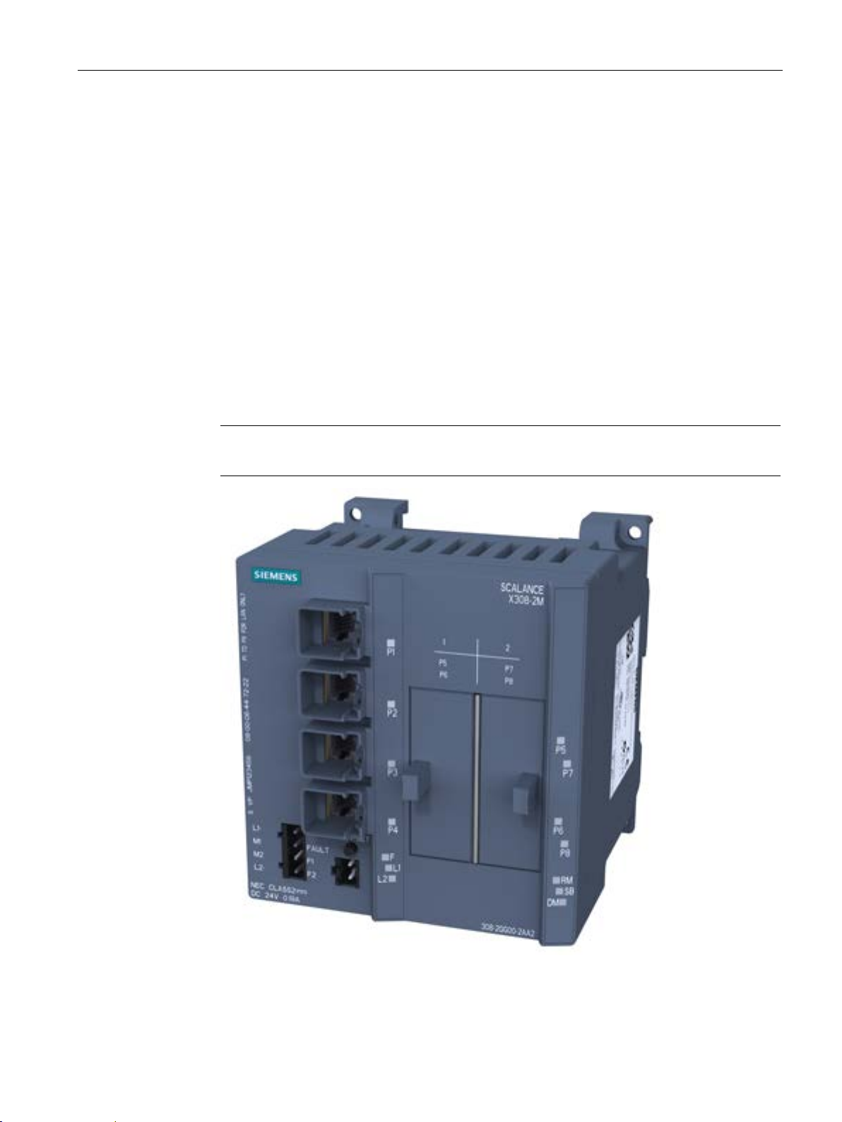
Description of the device
4.2.6
Product group X-300M PoE
4.2.6.1
SCALANCE X308-2M PoE product characteristics
Possible attachments
Four fixed ports in the base device:
Four modular ports via module slots:
Note
When shipped, the slots for the media modules have a dummy cover fitted.
4.2 Product groups
The SCALANCE X308-2M PoE is a partially modular device and has eight ports.
●
Four PoE-compliant ports (RJ-45 jacks with securing collars) for connection of end
devices or other network segments.
●
Two media modules (optical or electrical as required) can be combined using slots (S1S2) depending on the application. End devices and other network segments are
connected according to the media modules being used.
Image 4-22 SCALANCE X308-2M PoE with dummy covers
SCALANCE X-300
Operating Instructions, 05/2016, A5E01113043-20
71
Page 72
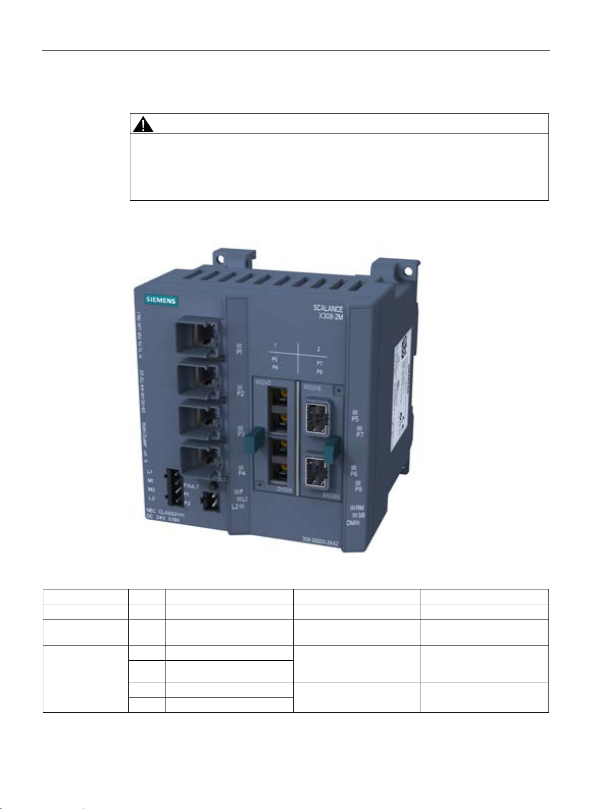
Description of the device
Possible attachments (example)
CAUTION
Use only approved media modules in the module slots
Example: Fitted with media modules MM992-2 and MM991-2
Column
1 2 3
4
Slot number
- - S1
S2
Media
modules used
Port number
-
P1 (gigabit Ethernet)
used)
-
P3 (gigabit Ethernet)
P8(interface depends on SFP
-
P4 (gigabit Ethernet)
4.2 Product groups
The connection of end devices or other network segments does not depend on the module
slot, but rather on the selected media module.
Refer to the section Media module installation in slot.
Image 4-23 SCALANCE X308-2M PoE with MM992-2 and MM992-2SFP
- - MM992-2 MM992-2SFP
- P2 (gigabit Ethernet)
SCALANCE X-300
72 Operating Instructions, 05/2016, A5E01113043-20
P5 (gigabit multimode fiberoptic cable, SC ports)
P6 (gigabit multimode fiberoptic cable, SC ports)
P7
(interface depends on SFP
used)
Page 73
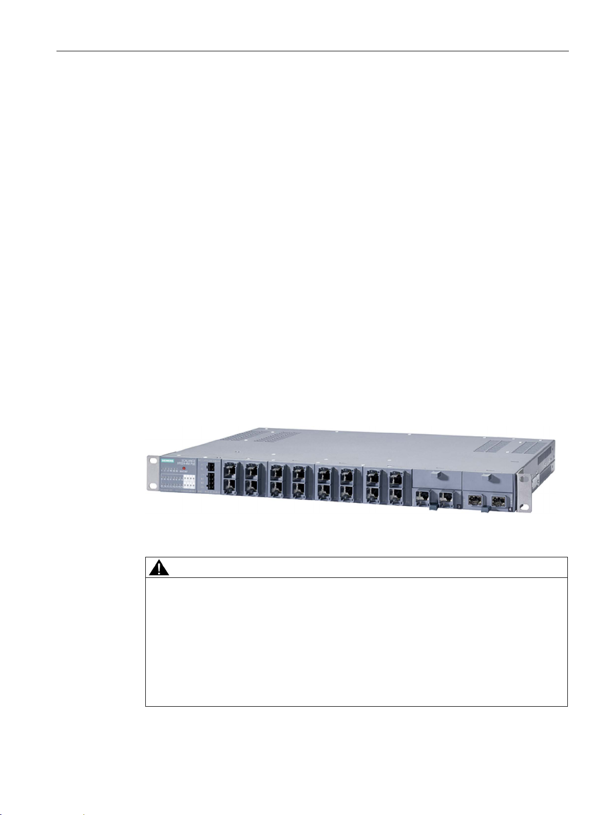
Description of the device
4.2.7
Product group XR-300M PoE
4.2.7.1
SCALANCE XR324-4M PoE product characteristics
Connection options of the SCALANCE XR324-4M PoE and XR324-4M PoE TS switches
16 fixed ports on the base device:
8 modular ports via 4 module slots:
CAUTION
Use only approved modules in the slots
4.2 Product groups
The switches are partly modular devices and all have 24 ports.
●
– Ports P1 to P8
8 PoE-compliant gigabit ports (RJ-45 jacks with securing collars) for connection of end
devices or other network segments.
Non PoE-compliant end devices can also be connected to the PoE-compliant RJ-45
jacks because the switches check that the end devices are suitable for the PoE
function before applying the power.
– Ports P9 to P16
8 gigabit ports (RJ-45 jacks with securing collars) for connection of end devices or
other network segments (no PoE).
●
4 media modules each with 2 ports are combined optically or electrically via the slots S1
to S4 depending on the application. End devices and other network segments are
connected according to the media modules being used.
Image 4-24 XR324-4M PoE and XR324-4M PoE TS
Possible module connection types:
• 2 x RJ-45
• 2 x FX100
• 2 x FX1000
• or 2 x SFP slots
With FX, single mode fibers or multimode fibers are possible.
SCALANCE X-300
Operating Instructions, 05/2016, A5E01113043-20
Connecting end devices or other network segments does not depend on the module slots.
73
Page 74
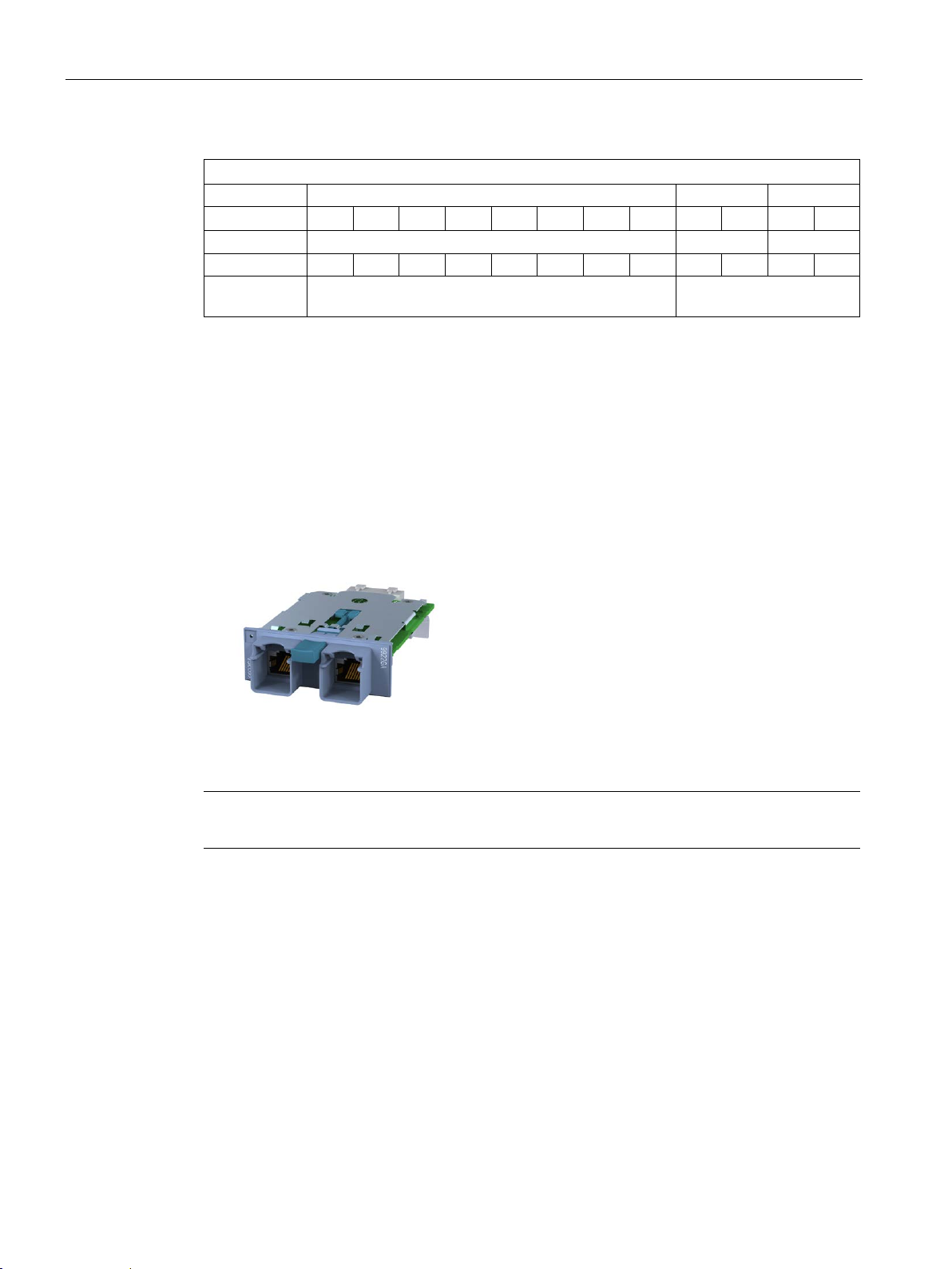
Description of the device
Slot number
S1
S2
Port number
Slot number
S3
S4
Port number
P9
P10
P11
P12
P13
P14
P15
P16
P1
P2
P1
P2
Connection
type
ing on module used
4.2.8
MM900 media modules
4.2.8.1
MM992-2CUC product characteristics
Possible attachments
Note
For connection to electrical networks note
4.2 Product groups
P1 P2 P3 P4 P5 P6 P7 P8 P1 P2 P1 P2
Electrical: Gigabit Ethernet Connection type depend-
The MM992-2CUC media module has the following:
● 2 x 10/100/1000 Mbps, RJ-45 ports electrical with securing collar
Image 4-25 MM992-2CUC [9922GA]
[Device labeling in square brackets]
the information in Appendix A.1 and A.2.
SCALANCE X-300
74 Operating Instructions, 05/2016, A5E01113043-20
Page 75
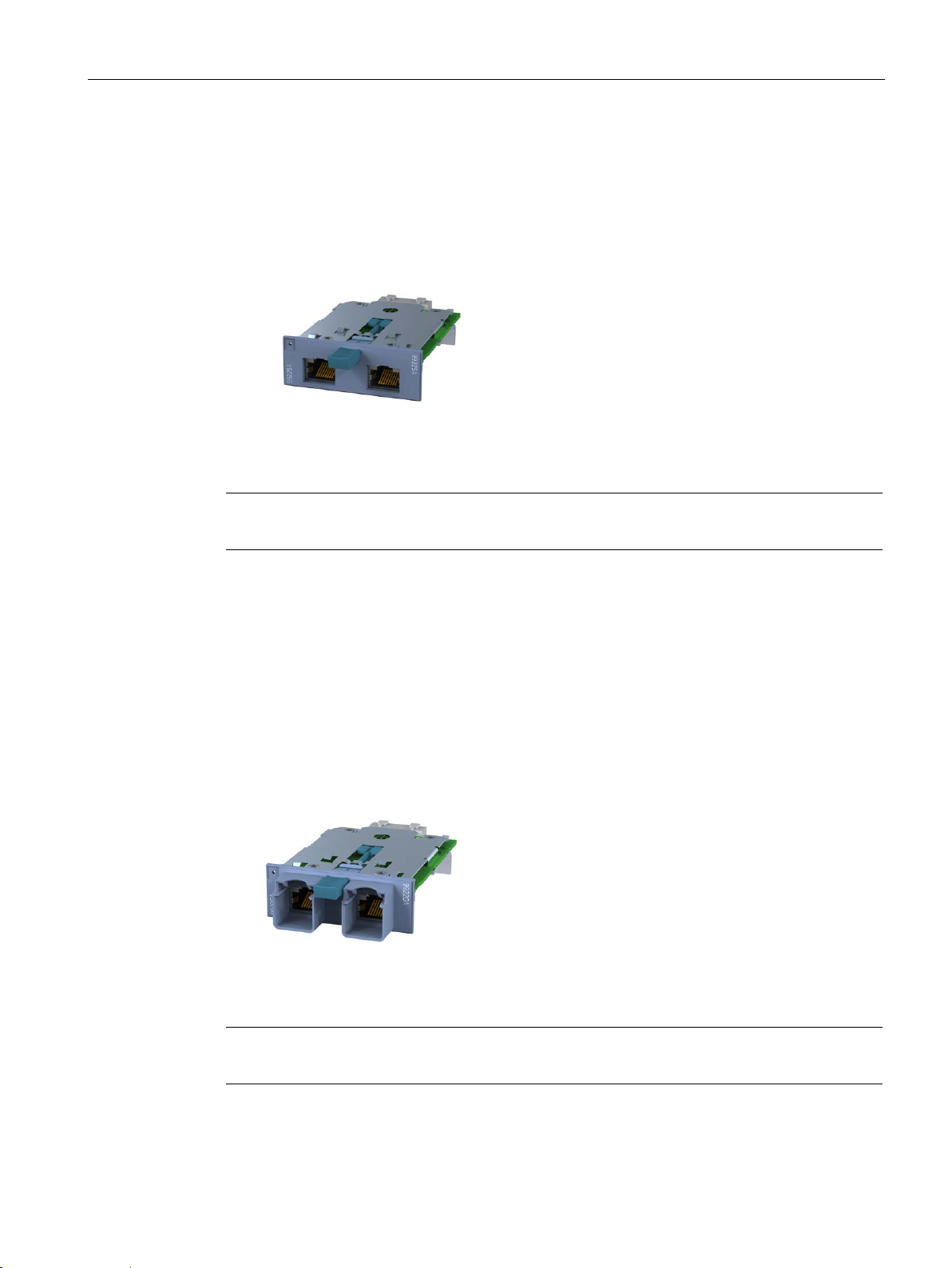
Description of the device
4.2.8.2
MM992-2CU product characteristics
Possible attachments
Note
For connection to electrical networks note the information in Appendix A.1 and A.2.
4.2.8.3
MM992-2VD product characteristics
Possible attachments
Note
For connection to electrical networks note the information in Appendix A.1 and A.2.
4.2 Product groups
The MM992-2CU media module has the following:
● 2 x 10/100/1000 Mbps, RJ-45 port electrical without securing collar
Image 4-26 MM992-2CU [9922SA]
[Device labeling in square brackets]
The MM992-2VD media module has the following:
● 2 x 10/100/1000 Mbps, RJ-45 ports electrical with securing collar
● Additional two-wire transfer function (variable distance) for establishing Ethernet
connections even using cables that do not conform to Ethernet. Possible distance
covered depends on the cable quality.
Image 4-27 MM992-2VD [9922VA]
[Device labeling in square brackets]
SCALANCE X-300
Operating Instructions, 05/2016, A5E01113043-20
75
Page 76
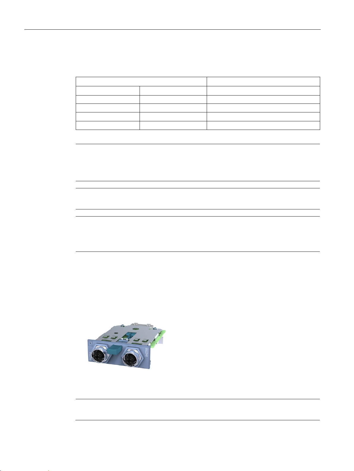
Description of the device
Pin assignment for the RJ-45 connector of a PROFIBUS cable
RJ-45 connectors
PROFIBUS cable
Pin assignment
Color
Wire color
1
Yellow
Green
2
Orange
Red
6
Blue
--
Note
Using PROFIBUS standard cable GP
If you use a PROFIBUS standard cable GP, the wires must be stripped before they are
inserted in the FC connector.
Note
If you use cables with a length > 500 m, connection establishment can take up to 2
Note
If you connect an MM992
requirements relating to shield contact and the lightning protection concept apply as for
PROFIBUS.
4.2.8.4
MM992-2M12 product characteristics
Possible attachments
Note
For connection to electrical networks note the information in
4.2 Product groups
If you use a PROFIBUS cable along with an IE FC RJ-45 plug 4x2, note the following:
3 White --
The MM992-2M12 media module has the following:
● 2 x 10/100/1000 Mbps, GE M12 connector electrical
Image 4-28 MM992-2M12C [9922HA]
min.
-2VD media module to existing PROFIBUS cabling, the same
[Device labeling in square brackets]
SCALANCE X-300
76 Operating Instructions, 05/2016, A5E01113043-20
Appendix (A.1, A.2 and A.3)
Page 77
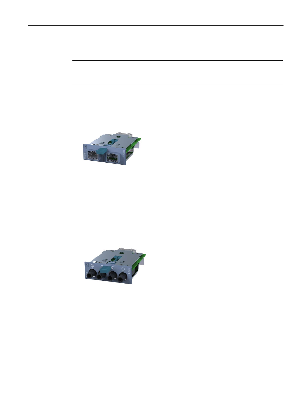
Description of the device
4.2.8.5
MM992-2SFP / MM992-2SFP (C) product properties
Note
Only the media modules MM992
transceivers. The SFP media modules can be fitted with up to two SFPs.
Possible attachments
4.2.8.6
MM991-2 product characteristics
Possible attachments
4.2 Product groups
The media modules MM992-2SFP / M992-2SFP (C) have:
● 2 x 100/1000 Mbps, SFP slot
Image 4-29 MM992-2SFP [9922AS]
[Device labeling in square brackets]
-2SFP / M992-2SFP (C) may be fitted with approved SFP
The MM991-2 media module has the following:
● 2 x 100 Mbps, BFOC port optical (multimode, glass) up to max. 5 km
Image 4-30 MM991-2 [9912AB]
[Device labeling in square brackets]
SCALANCE X-300
Operating Instructions, 05/2016, A5E01113043-20
77
Page 78
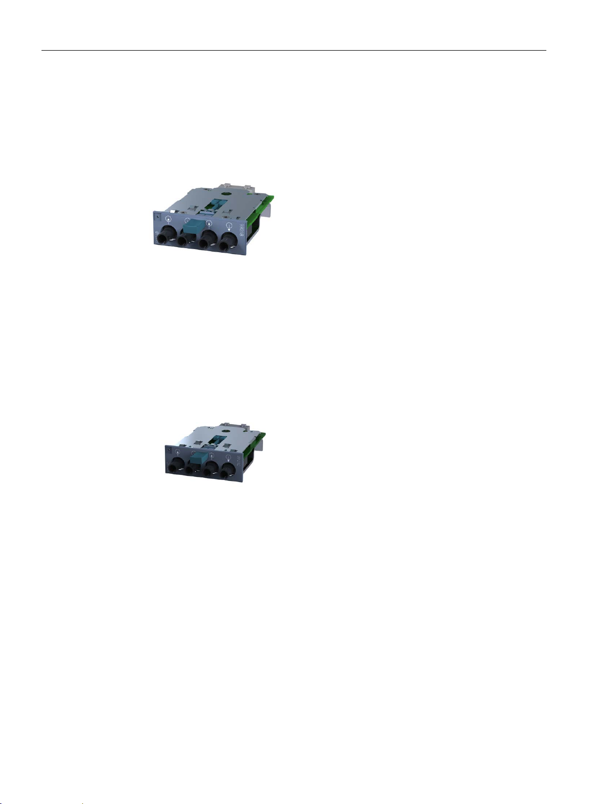
Description of the device
4.2.8.7
MM991-2FM product characteristics
Possible attachments
4.2.8.8
MM991-2LD product characteristics
Possible attachments
4.2 Product groups
The MM991-2FM media module has the following:
● 2 x 100 Mbps, BFOC port optical (multimode, glass) with diagnostics up to max. 5 km
Image 4-31 MM991-2FM [9912AB]
[Device labeling in square brackets]
The MM991-2LD media module has the following:
● 2 x 100 Mbps, BFOC port optical, (single mode glass), up to max. 26 km
Image 4-32 MM991-2LD [9912AC]
[Device labeling in square brackets]
SCALANCE X-300
78 Operating Instructions, 05/2016, A5E01113043-20
Page 79
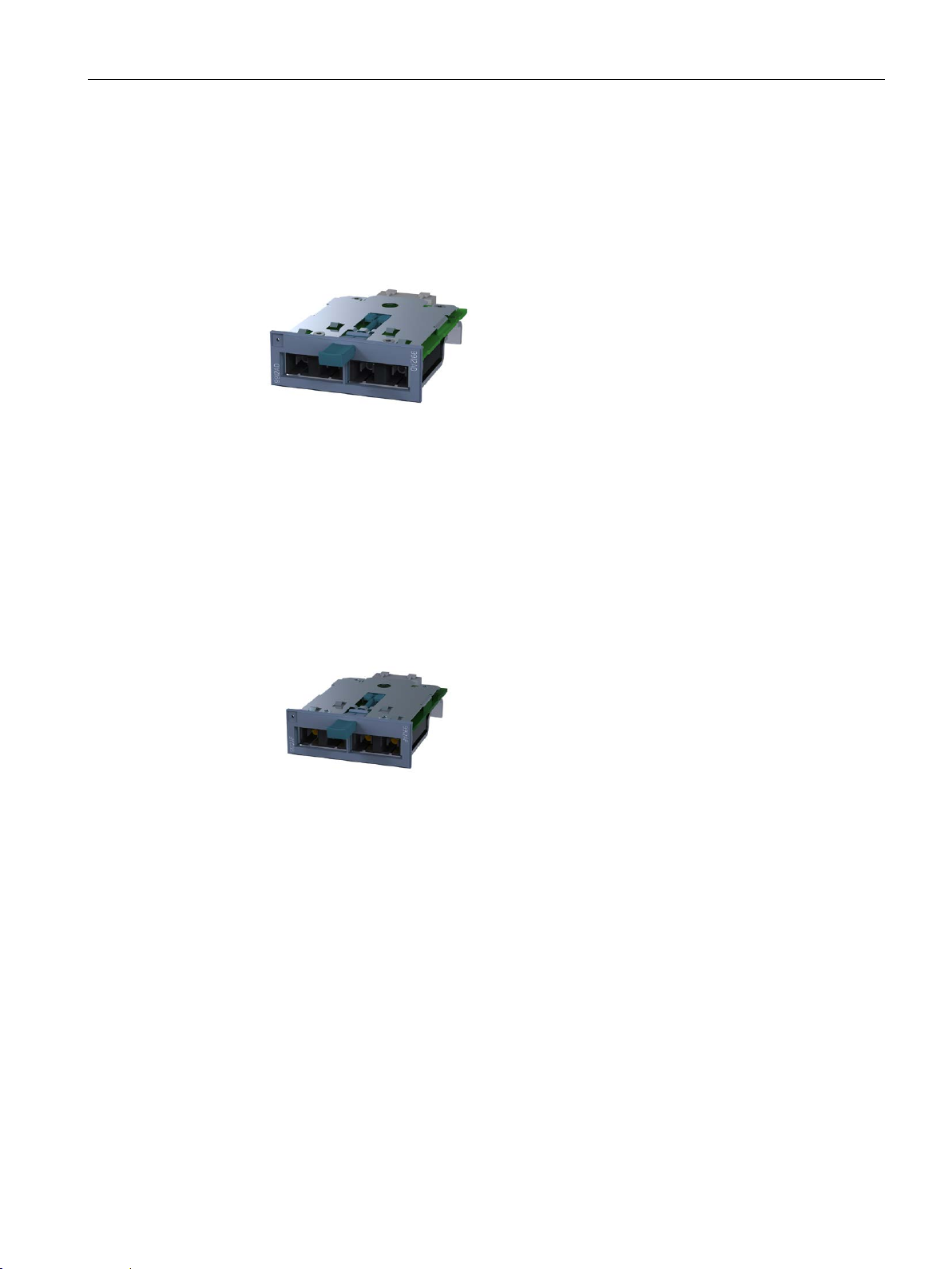
Description of the device
4.2.8.9
MM991-2 (SC) product characteristics
Possible attachments
4.2.8.10
MM991-2LD (SC) product characteristics
Possible attachments
4.2 Product groups
The MM991-2 (SC) media module has the following:
● 2 x 100 Mbps, SC port optical, (multimode glass), up to max. 5 km
Image 4-33 MM991-2 (SC) [9912AD]
[Device labeling in square brackets]
The MM991-2LD (SC) media module has the following:
● 2 x 100 Mbps, SC port optical, (single mode glass), up to max. 26 km
Image 4-34 MM991-2LD (SC) [9912AF]
[Device labeling in square brackets]
SCALANCE X-300
Operating Instructions, 05/2016, A5E01113043-20
79
Page 80
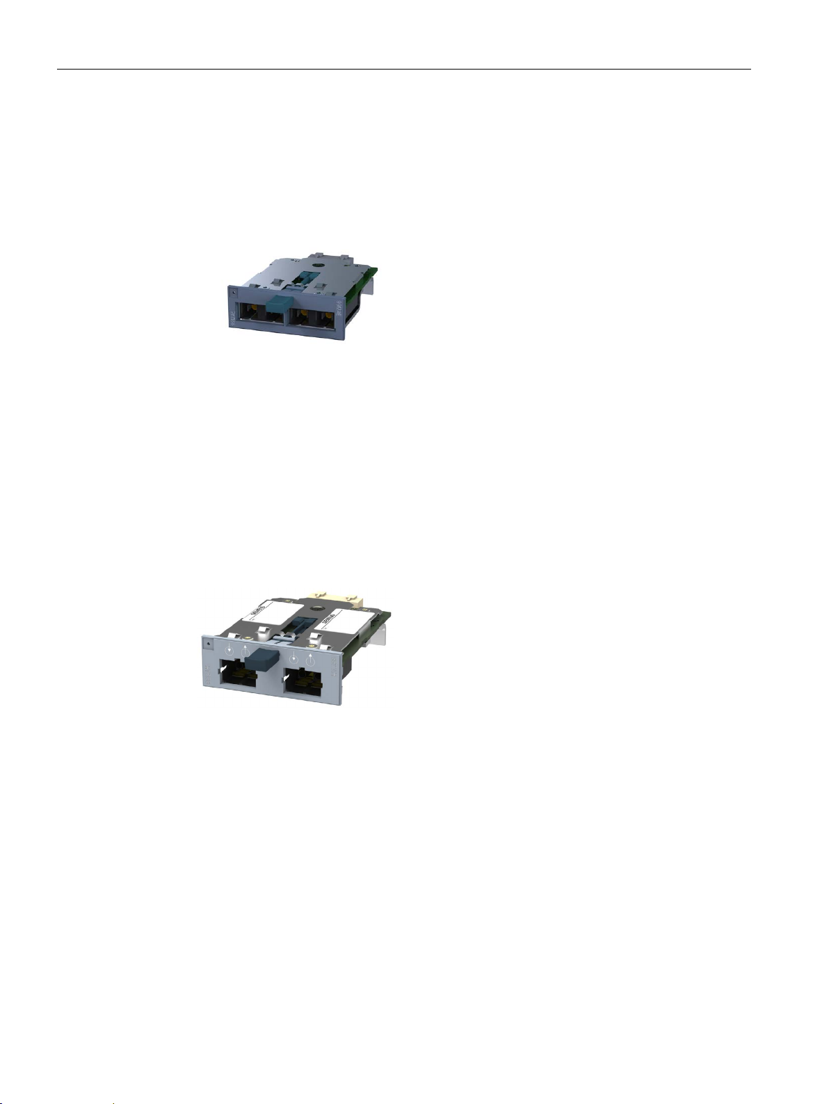
Description of the device
4.2.8.11
MM991-2LH+ (SC) product characteristics
Possible attachments
4.2.8.12
MM991-2P product characteristics
Possible attachments
4.2 Product groups
The MM991-2LH+ (SC) media module has the following:
● 2 x 100 Mbps, SC port optical, (single mode glass), up to max. 70 km
Image 4-35 MM991-2LH+ (SC) [9912AE]
[Device labeling in square brackets]
The MM991-2P media module has the following:
● 2 x 100 Mbps SC RJ ports optical for Plastic Optical Fiber (POF) up to max. 50 m or
Polymer Cladded Fiber (PCF) up to max. 100 m
Image 4-36 MM991-2P [9912AH]
[Device labeling in square brackets]
SCALANCE X-300
80 Operating Instructions, 05/2016, A5E01113043-20
Page 81
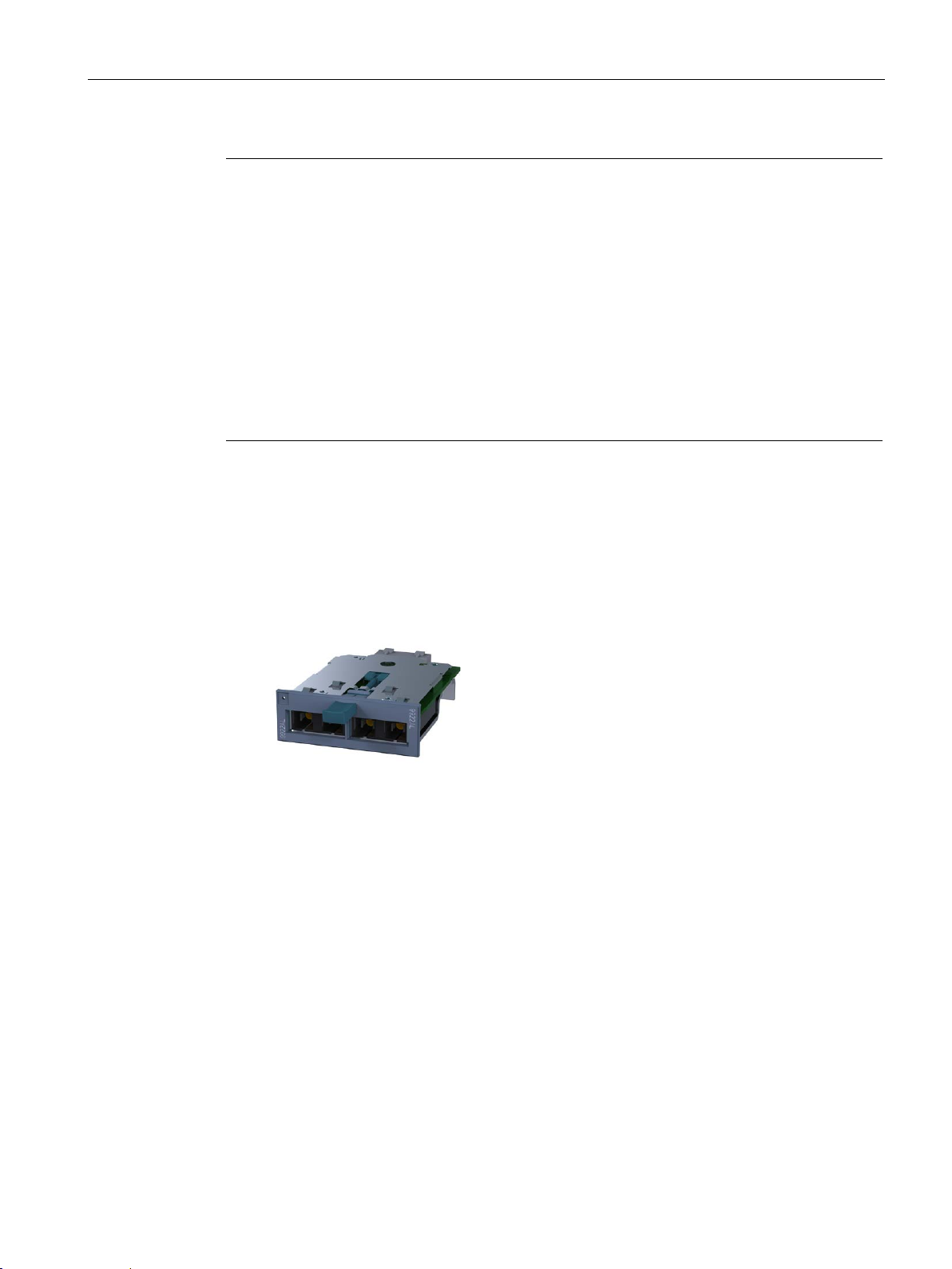
Description of the device
Note
Installation of the XR-300M, XR-300M PoE and XR-300M EEC
Only the lower slots may be equipped with the MM991
•
•
The slot above an MM991
•
•
Example XR
in slot 2.
See also table: "Operating temperature with media module MM991
4.2.8.13
MM992-2 product characteristics
Possible attachments
4.2 Product groups
-2P.
XR-300M: Maximum 6 modules in slots 7 to 12
XR-300M PoE, XR-300M EEC: Maximum 2 modules in slots 3 and 4
-2P may only be used as follows:
Without media module
With media module MM992-2CUC or MM992-2CU
-300M: If the MM991-2P is plugged into slot 8, an MM992-2CUC may be used
-2P"
The MM992-2 media module has the following:
● 2 x 1000 Mbps, SC port optical, (multimode glass), up to max. 750 m
Image 4-37 MM992-2 [9922AL]
[Device labeling in square brackets]
SCALANCE X-300
Operating Instructions, 05/2016, A5E01113043-20
81
Page 82
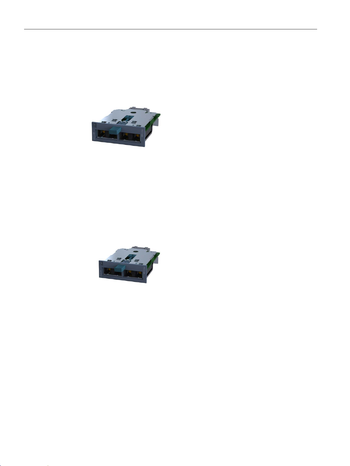
Description of the device
4.2.8.14
MM992-2LD product characteristics
Possible attachments
4.2.8.15
MM992-2LH product characteristics
Possible attachments
4.2 Product groups
The MM992-2LD media module has the following:
● 2 x 1000 Mbps, SC port optical, (single mode glass), up to max. 10 km
Image 4-38 MM992-2LD [9922AM]
[Device labeling in square brackets]
The MM992-2LH media module has the following:
● 2 x 1000 Mbps, SC port optical, (single mode glass), up to max. 40 km
Image 4-39 MM992-2LH [9922AN]
[Device labeling in square brackets]
SCALANCE X-300
82 Operating Instructions, 05/2016, A5E01113043-20
Page 83
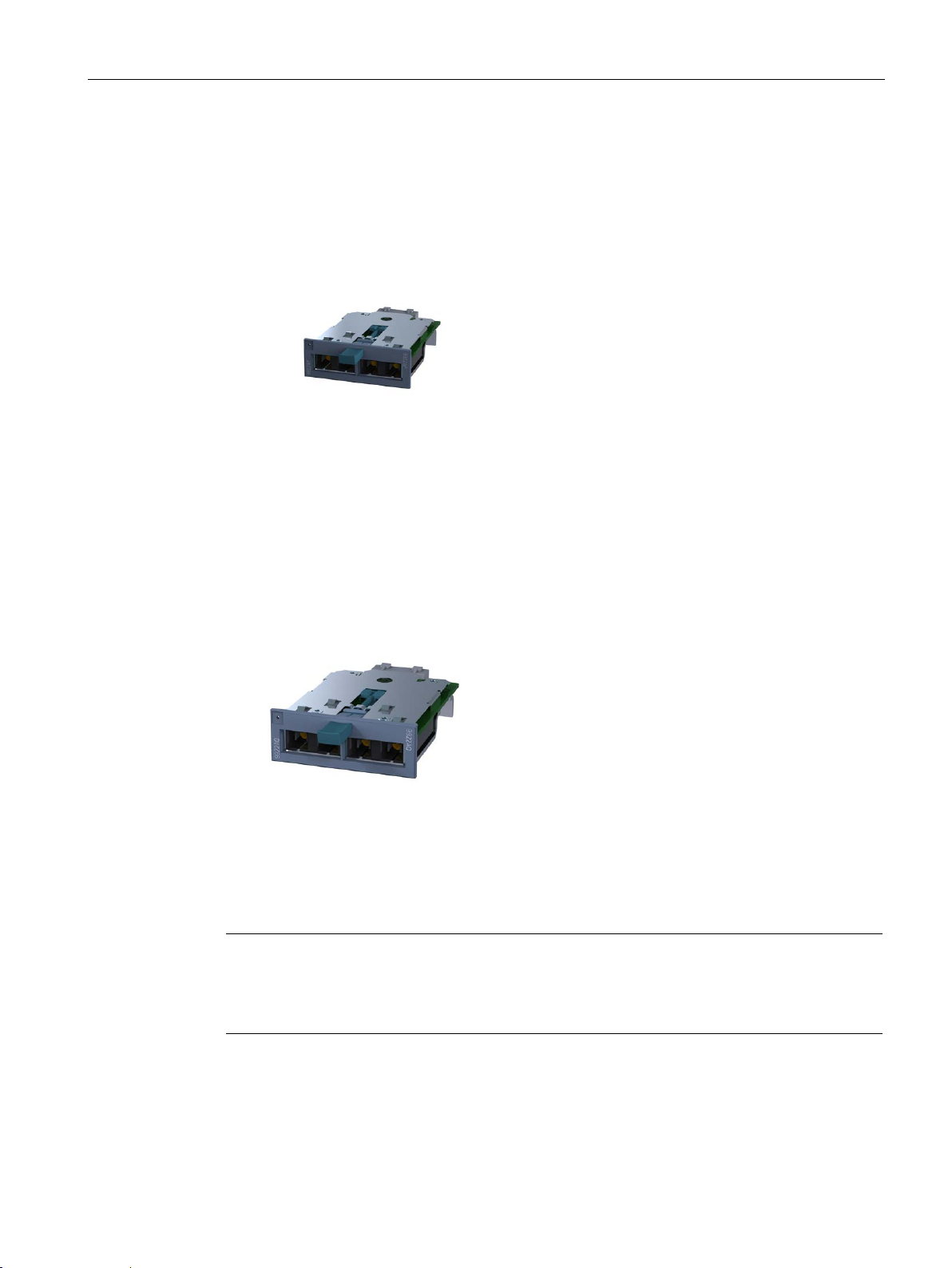
Description of the device
4.2.8.16
MM992-2LH+ product characteristics
Possible attachments
4.2.8.17
MM992-2ELH product characteristics
Possible attachments
4.2.8.18
General notes on MM900
Note
Use media modules only in an approved modular device ("M")
Use an MM900 media module only in a device equipped with suitable slots for such
modules. Example: X308
4.2 Product groups
The MM992-2LH+ media module has the following:
● 2 x 1000 Mbps, SC port optical, (single mode glass), up to max. 70 km
Image 4-40 MM992-2LH+ [9922AP]
[Device labeling in square brackets]
The MM992-2ELH media module has the following:
● 2 x 1000 Mbps, SC port optical, (single mode glass), up to max. 120 km
Image 4-41 MM992-2ELH [9922AQ]
[Device labeling in square brackets]
-2M.
SCALANCE X-300
Operating Instructions, 05/2016, A5E01113043-20
83
Page 84
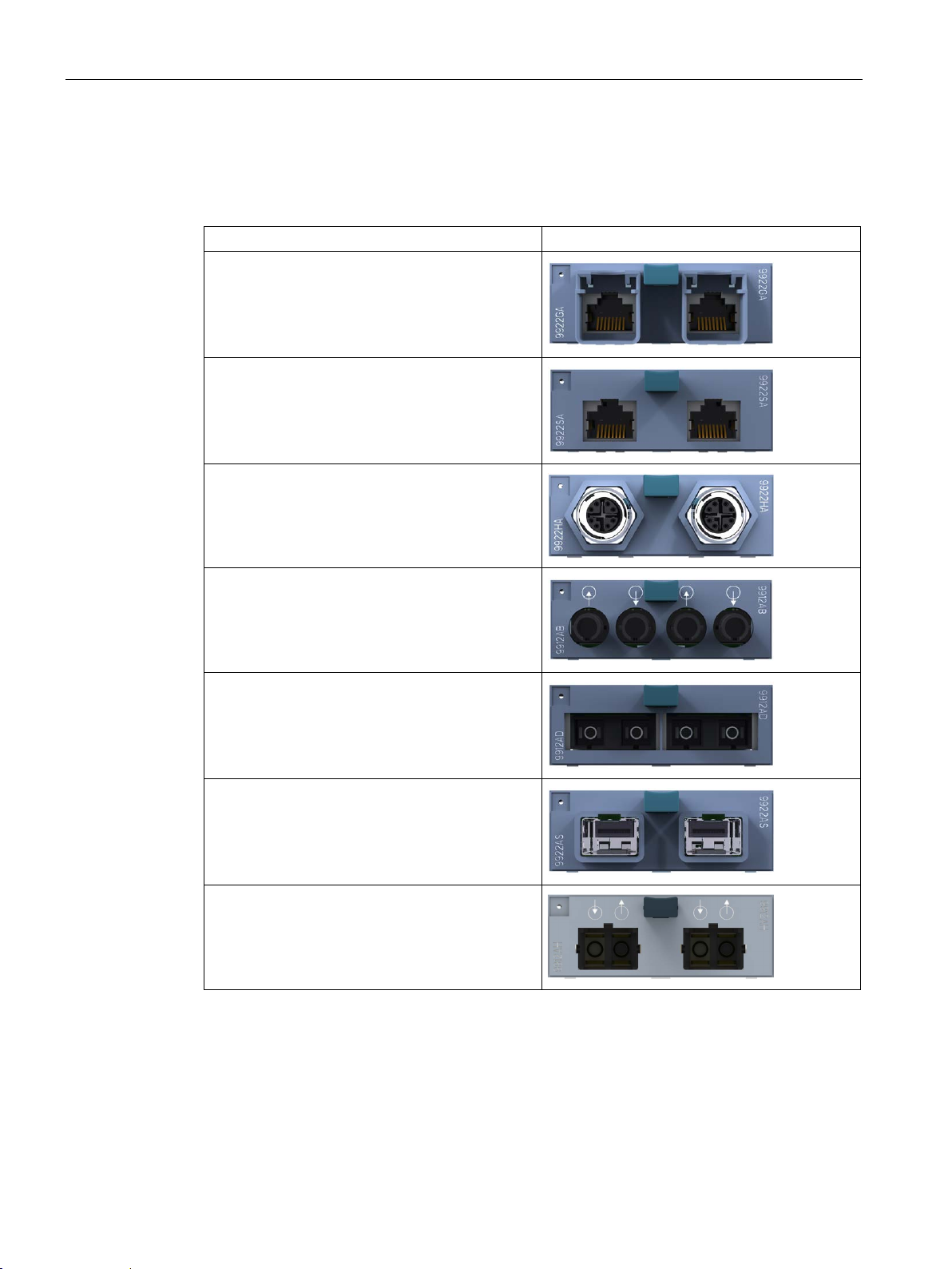
Description of the device
The MM900 media module decides what can be connected
Possible attachment
Figure
4.2 Product groups
The connection of end devices or other network segments does not depend on the module
slot, but rather on the selected MM900 media module.
Electrical RJ-45 ports with securing collar
Electrical RJ-45 ports without securing collar
GE M12 connector electrical
BFOC ports optical
Optical SC ports
SFP transceivers
Only the SFP media module MM992-2SFP may be
fitted with approved SFP transceivers. The SFP
media module can be fitted with up to two SFPs.
SC RJ ports optical
SCALANCE X-300
84 Operating Instructions, 05/2016, A5E01113043-20
Page 85
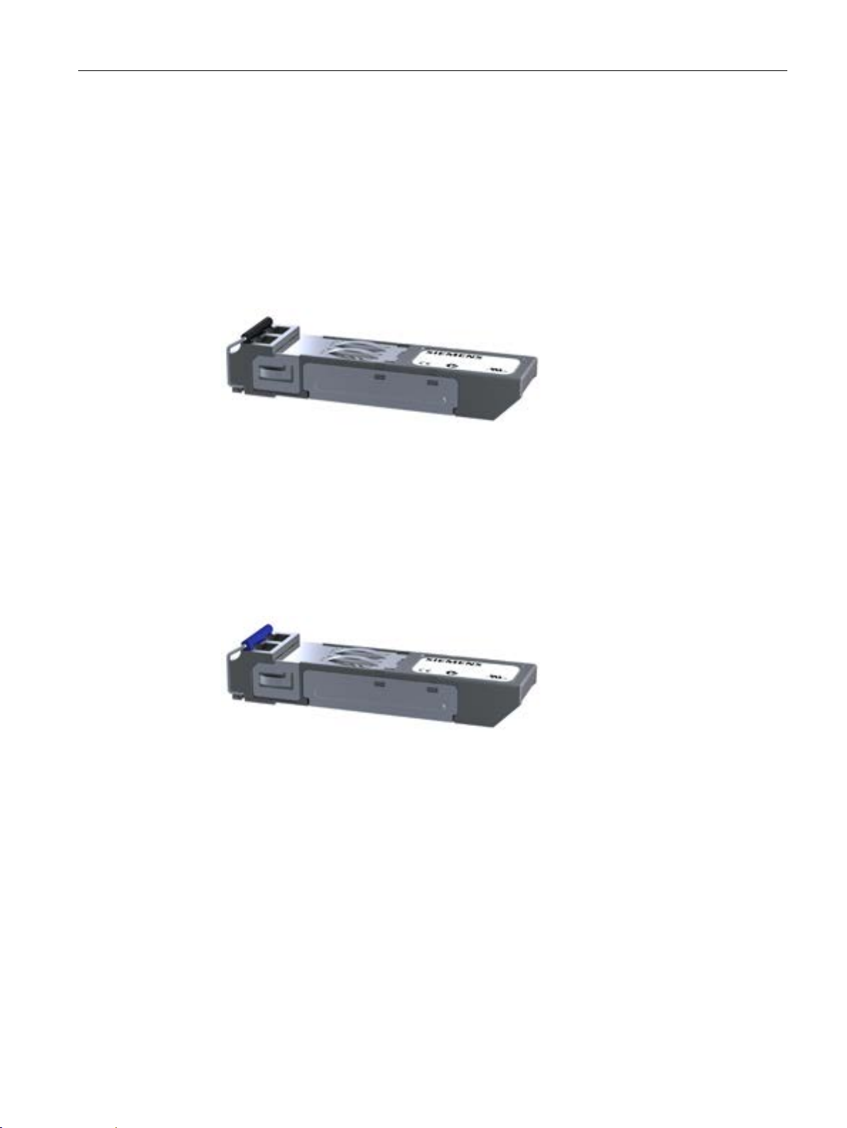
Description of the device
4.2.9
SFP transceiver
4.2.9.1
SCALANCE SFP991-1 product characteristics
Possible attachments
SFP991-1
4.2.9.2
SCALANCE SFP991-1LD product characteristics
Possible attachments
SFP991-1LD
4.2 Product groups
The
● 1 x 100 Mbps, LC port optical (multimode, glass) up to max. 3 km
Image 4-42 SFP991-1
The
● 1 x 100 Mbps, LC port optical (single mode, glass) up to max. 26 km
transceiver has the following:
transceiver has the following:
Image 4-43 SFP991-1LD
SCALANCE X-300
Operating Instructions, 05/2016, A5E01113043-20
85
Page 86
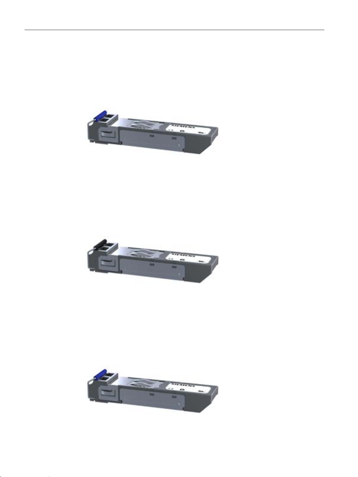
Description of the device
4.2.9.3
SCALANCE SFP991-1LH+ product characteristics
Possible attachments
SFP991-1LH+
4.2.9.4
SCALANCE SFP992-1 product characteristics
Possible attachments
SFP992-1
4.2.9.5
SCALANCE SFP992-1LD product characteristics
Possible attachments
SFP992-1LD
4.2 Product groups
The
● 1 x 100 Mbps, LC port optical (single mode, glass) up to max. 70 km
Image 4-44 SFP991-1LH+
The
● 1 x 1000 Mbps, LC port optical (multimode, glass) up to max. 750 m
transceiver has the following:
transceiver has the following:
Image 4-45 SFP992-1
The
● 1 x 1000 Mbps, LC port optical (single mode, glass) up to max. 10 km
Image 4-46 SFP992-1LD
SCALANCE X-300
86 Operating Instructions, 05/2016, A5E01113043-20
transceiver has the following:
Page 87

Description of the device
4.2.9.6
SCALANCE SFP992-1LH product characteristics
Possible attachments
SFP992-1LH
4.2.9.7
SCALANCE SFP992-1LH+ product characteristics
Possible attachments
SFP992-1LH+
4.2.9.8
SCALANCE SFP992-1ELH product characteristics
Possible attachments
SFP992-1ELH
4.2 Product groups
The
● 1 x 1000 Mbps, LC port optical (single mode, glass) up to max. 40 km
Image 4-47 SFP992-1LH
The
● 1 x 1000 Mbps, LC port optical (single mode, glass) up to max. 70 km
transceiver has the following:
transceiver has the following:
Image 4-48 SFP992-1LH+
The
● 1 x 1000 Mbps, LC port optical (single mode, glass) up to max. 120 km
Image 4-49 SFP992-1ELH
SCALANCE X-300
Operating Instructions, 05/2016, A5E01113043-20
transceiver has the following:
87
Page 88
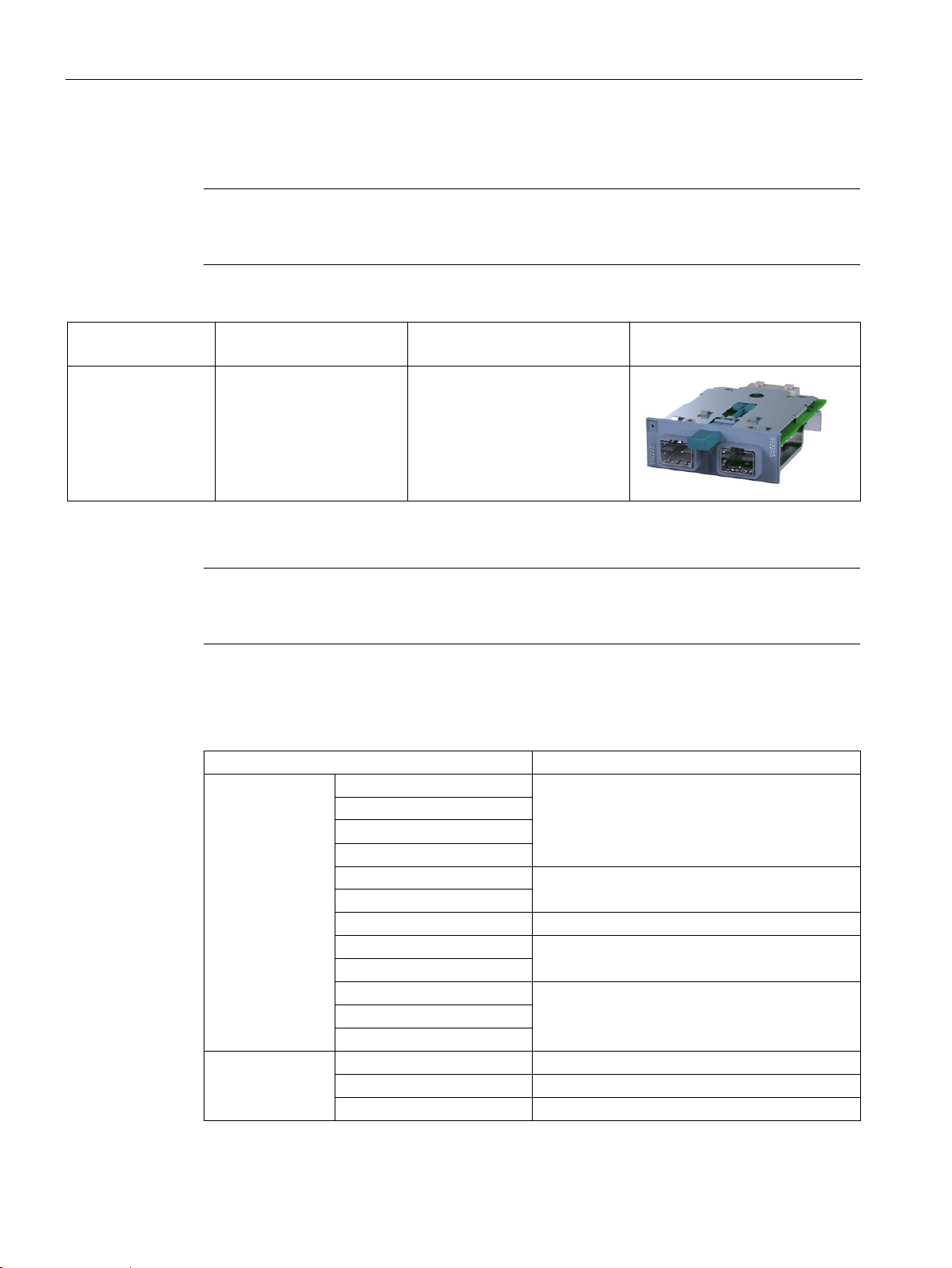
Description of the device
4.2.9.9
General notes on SFP
Note
Only the media module MM992
SFP media module can be fitted with up to two SFPs.
Device:
Media module
(Variant)
[Order number]
Labeling on the device
Figure
Note
An SFP with
protect the pins, these are fitted with a dummy plug.
4.2.9.10
Supported wavelengths of the SFPs
Pluggable transceiver
Supported wavelength
SFP
SFP991-1
SFP991-1 (C)
SFP991-1LD
SFP991-1LD (C)
SFP991-1ELH200
SFP992-1LD
SFP992-1LD (C)
SFP992-1LH
SFP992-1LH+
SFP992-1ELH
SFP+
SFP993-1
850 nm
SFP993-1LD
1310 nm
SFP993-1LH
1550 nm
4.2 Product groups
MM992-2SFP (2 x 100/1000 Mbps,
SFP media module)
multimode has a black clip and an SFP with single mode has a blue clip. To
-2SFP may be fitted with approved SFP transceivers. The
[6GK5 992-2AS00-8AA0]
9922AS
SFP991-1LH+ 1550 nm
SFP992-1 850 nm
1310 nm
1310 nm
1550 nm
SCALANCE X-300
88 Operating Instructions, 05/2016, A5E01113043-20
Page 89

Description of the device
SCP
SCP992-1
850 nm
SCP992-1LD
1310 nm
STP
STP991-1
STP991-1LD
4.3
Interfaces and signaling contact of the switches
4.3.1
Ethernet interfaces - electrical ports
4.3.1.1
10Base-T / 100Base-TX
Transmission rate
Transmission mode
4.3 Interfaces and signaling contact of the switches
The transmission rate of the electrical ports is 10 Mbps or as Fast Ethernet ports 100 Mbps.
The transmission mode for 10Base-T / 100Base-TX is specified in the IEEE 802.3i / IEEE
802.3u standards of the Institute of Electrical and Electronic Engineers.
1310 nm
Autonegotiation (automatic detection of the best transmission modes) is default. The order in
which they are selected is:
● 100Base-TX full duplex
● 100Base-TX half duplex
● 10Base-T full duplex
● 10Base-T half duplex
Two communication modes are possible:
● Half duplex
Two-way alternate transmission mode - it is only possible to either send or receive over
the interfaces at any one time.
● Full duplex mode
Two-way simultaneous - both communication partners can send and receive at the same
time.
Connections to other switches can use half or full duplex; connections to hubs are possible
only in half duplex mode.
SCALANCE X-300
Operating Instructions, 05/2016, A5E01113043-20
89
Page 90

Description of the device
Transmission medium
Transmission range
Connectors
Note
The RJ
tensile and bending relief are provided by the securing bracket using a cable binder, see also
section
4.3.1.2
1000Base-T
Transmission rate
Transmission mode
4.3 Interfaces and signaling contact of the switches
Data transmission at 10 Mbps and at 100 Mbps is over two wire pairs (pin 1, 2, 3, 6) of the
twisted pair cable. For 10 Mbps, at least a category 3 (Cat 3) and for 100 Mbps, at least a
four-wire (2 x 2) category 5 (Cat 5) cable is necessary.
The maximum transmission range (segment length) is 100 m.
A node or network segment is connected to an 8-pin RJ-45 jack with securing collar. Due to
its flush fitting with an IE FC RJ-45 Plug 180 / IE FC RJ45 Plug 145 connector, the securing
collar ensures a robust connection suitable for industry that provides tensile and bending
strain relief for the inserted connector.
-45 jacks of the SCALANCE X300EEC variants do not have a securing collar. The
The transmission rate of the electrical Ethernet ports is 10 Mbps, as Fast Ethernet ports 100
Mbps or as gigabit ports 1 Gbps.
The transmission mode for 1000Base-T is specified in the IEEE 802.3ab standard.
Autonegotiation (automatic detection of the best transmission mode) is default.
The order in which they are selected is:
● 1000Base-T full duplex
● 1000Base-T half duplex
● 100Base-TX full duplex
● 100Base-TX half duplex
Signaling contact (Page 145).
● 10Base-T full duplex
● 10Base-T half duplex
SCALANCE X-300
90 Operating Instructions, 05/2016, A5E01113043-20
Page 91

Description of the device
Transmission medium
Note
For data transmission at 1 Gbps,
necessary. With a four
Mbps is possible.
Transmission range
Connectors
4.3.1.3
Power over Ethernet (PoE)
Power over Ethernet (PoE)
4.3 Interfaces and signaling contact of the switches
Two communication modes are possible:
● Half duplex
Two-way alternate transmission mode - it is only possible to either send or receive over
the interfaces at any one time.
● Full duplex mode
Two-way simultaneous - both communication partners can send and receive at the same
time.
Data is transmitted over an eight-wire twisted pair cable.
at least a Cat 5e twisted-pair cable with 4 x 2 wires is
-wire cable (2 x 2 wires), a maximum data transmission rate of 100
The maximum transmission range (segment length) is 100 m.
The connectors used are 8-pin RJ-45 jacks.
With PoE, the power for networked devices is carried via Ethernet. Here, there are two
methods of supplying power:
● Alternative A
Here, the voltage is transferred on the data wires 1, 2, 3 and 6 of the Ethernet cable
Requirements for the Ethernet cable:
– For 10Base-T/100Base-TX, a 4-wire cable is adequate for data transmission and
power supply.
– With 1000BASE-T, an 8-wire cable is necessary for data transmission.
SCALANCE X-300
Operating Instructions, 05/2016, A5E01113043-20
● Alternative B
Power is transferred on the free wires 4, 5, 7 and 8 of the Ethernet cable.
Requirements for the Ethernet cable: For 10Base-T/100Base-TX/1000BASE-T, an 8-wire
cable is needed.
91
Page 92

Description of the device
4.3.1.4
Ports of the X308-2M PoE
The PoE ports of the switch
Note
The total power provided by the SCALANCE X308
maximum of 30.8 W.
Possible attachments
4 electrical ports
4 modular ports via 2 module slots
4.3 Interfaces and signaling contact of the switches
PoE-compliant devices can be divided into the following groups:
● PSE - power sourcing equipment
These inject power onto the Ethernet cable.
● PD - powered devices
These are supplied with power via Ethernet.
As a PSE, the X308-2M PoE supplies PoE-compliant devices with power over Ethernet. The
48 V power required to supply the powered devices is generated internally on the switch, no
extra power supply unit is necessary.
The X308-2M PoE uses the "alternative A" for this. Per RJ-45 port, a maximum of 15.4 W
are available for supplying a PoE-compliant device. If a Cat5/Cat5e cable with a maximum
length of 100 m is used, the connected device can be supplied with a power of 12.95 W.
The PoE ports meet the conditions listed in the IEEE 802.3af / IEEE 802.3at standard
(type 1) for environment A , in other words power supply over Ethernet within a power supply
system. For details of configuring and enabling PoE for individual ports, refer to the
configuration manual SCALANCE X-300 / X-400 on the accompanying CD.
-2M PoE on all four PoE ports is a
The X308-2M PoE is a partially modular device and has 4 fixed ports and 2 slots for media
modules.
●
4 PoE-compliant RJ-45 jacks with securing collars for connection of end devices or
network segments. Non PoE-compliant end devices can also be connected to the PoEcompliant RJ-45 jacks because the X308-2M PoE checks that the end devices are
suitable for the PoE function before applying the power.
●
2 media modules each with 2 ports are combined optically or electrically via the slots S1
and S2 depending on the application.
End devices and other network segments are connected according to the media modules
being used.
SCALANCE X-300
92 Operating Instructions, 05/2016, A5E01113043-20
Page 93

Description of the device
4.3.1.5
PoE ports
PoE ports of the SCALANCE XR324-4M PoE and XR324-4M PoE TS switches
Note
The total power provided by the switches on all eight PoE ports is a maximum of 53.2 W.
4.3.1.6
Isolation between the TP ports
Note
Exceptions are X307-3, X307-3LD, X308-2, X308-2LD, X308-2LH, X308-2LH+, X310,
X310FE
The following port group is an exception to this:
•
Between the ports of port group 1, the requirements for Environment A are met.
4.3.2
Ethernet interfaces - optical ports
4.3.2.1
1000Base-SX
Transmission rate
4.3 Interfaces and signaling contact of the switches
As PSEs, these devices supply PoE-compliant devices with power over Ethernet. The power
required to supply the powered devices is generated internally on the switches, no extra
power supply unit is necessary.
The switches use the "Alternative A" method. Per RJ-45 port, a maximum of 15.4 W are
available for supplying a PoE-compliant device. If a Cat5/Cat5e cable with a maximum
length of 100 m is used, the connected device can be supplied with a power of 12.95 W.
The PoE ports meet the conditions listed in the IEEE 802.3af / IEEE 802.3at standard
(type 1) for environment A , in other words power supply over Ethernet within a power supply
system. For details of configuring and enabling PoE for individual ports, refer to the
configuration manual SCALANCE X-300 / X-400 on the accompanying CD.
All ports meet the requirement of 1.5 kV isolation voltage to the shield and between the ports
(corresponds to IEEE802.3, Environment B).
Port group 1: P1, P2, P3 and P4
The transmission rate of the optical gigabit ports is 1 Gbps.
SCALANCE X-300
Operating Instructions, 05/2016, A5E01113043-20
93
Page 94

Description of the device
Transmission mode
Transmission medium
Transmission range
Connectors
4.3.2.2
1000Base-LX / 100Base-FX
Transmission rate
Transmission mode
Transmission medium
Transmission range
4.3 Interfaces and signaling contact of the switches
Transmission with 1000Base-SX is defined in the IEEE 802.3z standard and is specified as
1000 Mbps transmission rate and full duplex.
Data is transmitted over multimode FOC. The wavelength is 850 nm.
The core diameter of the multimode FOC is 50 µm; the light source is an LED. Many modes
(light beams) are used for signal transmission. The propagation times of the light pulses
(dispersion) restrict the maximum range considerably.
The maximum transmission range (segment length) is 750 m when using SIMATIC NET
fiber-optic multimode FOC with SC duplex connectors.
SC duplex female connectors are used.
On the IE Switches X-300EEC, devices are connected via LC jacks.
The transmission rate of the optical gigabit ports is 1 Gbps.
Transmission with 1000Base-LX is defined in the IEEE 802.3z standard and is specified as
1000 Mbps transmission rate and full duplex.
Data is transmitted over single mode FOC. The wavelength is 1310 nm or 1550 nm.
The core diameter of the single mode FO cable is 9 or 10 µm; the light source is a laser
diode. To transmit a signal, only one mode (light beam) is used greatly reducing dispersion.
As a result, the maximum range of single mode FOC is greater than that of multimode FOC.
The maximum transmission distance (segment length) is 120 km for 1000Base-LX
transmission.
SCALANCE X-300
94 Operating Instructions, 05/2016, A5E01113043-20
Page 95

Description of the device
IE Switches X-300 connector technology
Connector technology of the IE Switch X-300EEC
4.3.3
Signaling contact
Error indication
4.4
C-PLUG (configuration plug)
NOTICE
4.4 C-PLUG (configuration plug)
SC duplex female connectors are used.
FC duplex female connectors with the following characteristics are used:
● Maximum range: up to 3 km
● Wavelength: 1310 nm
● Transmission mode: Multimode
● Standard: 100Base-FX
The signaling contact (relay contact) is a floating switch with which error/fault states can be
signaled by breaking the contact.
● The signaling by the signaling contact is synchronized with the fault LED, in other words,
all errors displayed by this LED (freely configurable) are also signaled on the signaling
contact.
● If an internal fault occurs, the fault LED lights up and the signaling contact opens.
● The connection or disconnection of a communication node on an unmonitored port does
not lead to an error message.
● The signaling contact remains activated until the error/fault is eliminated or until the
current status is entered in the fault mask as the new desired status.
DO NOT REMOVE C-PLUG WHILE POWER IS ON
The C-PLUG may only be removed or inserted when the power supply to the device is
turned off.
In a device with a varnished printed circuit board, you may only use a C-PLUG with a
varnished board.
SCALANCE X-300
Operating Instructions, 05/2016, A5E01113043-20
95
Page 96

Description of the device
Area of application
How it works
Diagnostics
4.4 C-PLUG (configuration plug)
The C-PLUG is an exchangeable medium for storage of the configuration data of the IE
Switch and ships with the product. This means that the configuration data remains available
if the IE Switch is replaced.
Power is supplied by the IE Switch. The C-PLUG retains all data permanently when the
power is turned off.
If an empty C-PLUG (factory settings or deleted with the Clean function) is inserted, all the
configuration data of the IE Switch is saved to it automatically when the device starts up.
Changes to the configuration during operation without operator intervention are saved on the
C-PLUG if this is in the "ACCEPTED" status.
An IE Switch with an accepted C-PLUG inserted uses the configuration data of the C-PLUG
automatically when it starts up. Acceptance is possible only when the data was written by a
compatible device type.
This allows an IE Switch to be replaced quickly and simply. The C-PLUG is taken from the
failed component and inserted in the replacement. The first time it is started up, the
replacement device has the same configuration as the failed device except for the MAC
address set by the vendor.
Inserting a C-PLUG that does not contain the configuration of a compatible device type,
accidentally removing the C-PLUG or general malfunctions of the C-PLUG are signaled by
the diagnostics mechanisms of the IE Switch (LEDs, WEB-based management, SNMP, CLI
and PROFINET diagnostics).
SCALANCE X-300
96 Operating Instructions, 05/2016, A5E01113043-20
Page 97
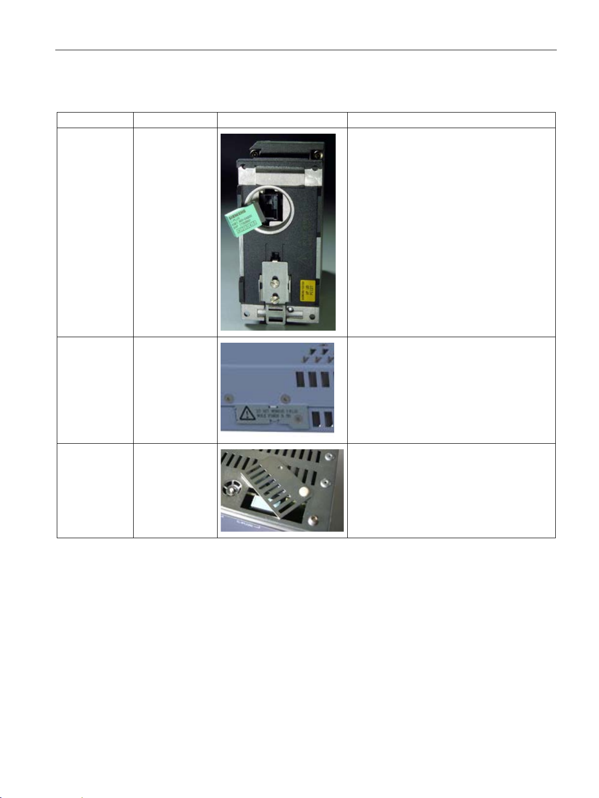
Description of the device
Inserting in the C-PLUG slot on the IE Switch X-300
Product group
Slot
Figure
C-PLUG
X-300
X-300M
XR-300M
X-300EEC
4.4 C-PLUG (configuration plug)
Rear of the device
Rear of the device
- right
1. Remove the screw cover.
2. Insert the C-PLUG in the intended slot.
3. Close the screw cover again correctly.
1. Remove the cover.
2. Insert the C-PLUG in the intended slot.
3. Close the cover again correctly.
Top of the housing
1. Open the slider.
2. Insert the C-PLUG.
3. Close the slider.
SCALANCE X-300
Operating Instructions, 05/2016, A5E01113043-20
97
Page 98
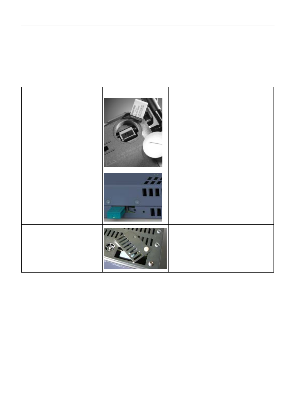
Description of the device
Removing the C-PLUG from the IE Switch X-300
Product group
Slot
Figure
X-300
X-300M
XR-300M
X-300EEC
4.4 C-PLUG (configuration plug)
It is only necessary to remove the C-PLUG if the IE Switch develops a fault.
The C-PLUG can be removed from the slot using flat pliers, tweezers, or a small screwdriver.
Rear of the device
Top of the housing
Rear of the device
- right
1. Remove the screw cover.
2. Remove the C-PLUG.
3. Close the screw cover again correctly.
1. Remove the cover.
2. Remove the C-PLUG.
3. Close the cover again correctly.
1. Open the slider.
2. Remove the C-PLUG.
3. Close the slider.
SCALANCE X-300
98 Operating Instructions, 05/2016, A5E01113043-20
Page 99

Description of the device
4.5
Components of the product
Unpacking, checking
WARNING
4.5.1
Components of the product
4.5.2
X-300M components of the product
Note
When shipped, all devices have a C
Note
When shipped, the slots
Note
Labels to identify the installed MM900 media modules are supplied with the modular devices
(M).
4.5 Components of the product
1. Make sure that the package is complete.
2. Check all the parts for transport damage.
Do not use any parts that show evidence of damage!
The following components are supplied with a SCALANCE X-300:
● Device with C-PLUG exchangeable medium.
● A four-pin terminal block for the 24 VDC power supply.
● A two-pin terminal block for the signaling contact.
● Product CD with documentation and software.
-PLUG exchangeable medium.
for the media modules have a dummy cover fitted.
SCALANCE X-300
Operating Instructions, 05/2016, A5E01113043-20
99
Page 100

Description of the device
X-300M
Device:
SCALANCE
Variant
Plug-in terminal block
Device
BAK
Product CD
Signaling
contact
Power supply
X308-2M
(-)
2-pin
4-pin (24 V)
● ● ●
X308-2M TS
(-)
2-pin
4-pin (12 V)
● ● ●
4.5.3
Components of the XR-300M product
Note
When
Note
Labels to identify the installed MM900 media modules are supplied with the modular devices
(M).
4.5 Components of the product
Table 4- 1 Overview of the components shipped with the
shipped, the slots for the media modules have dummy covers fitted.
The following parts ship with a SCALANCE XR-300M:
product group
● Device with C-PLUG exchangeable medium.
● 2 mounting brackets and 8 screws (M3x5 recessed head, drive: Torx) for 19" rack
installation.
● A two-pin terminal block for the signaling contact.
● Connecting cable for the diagnostics port.
● Adhesive feet for desktop operation.
● Product CD with documentation and software.
For devices with a 100 to 240 VAC power supply also:
● A two-pin connector for the power supply.
For devices with a 24 VDC power supply, also:
● A four-pin terminal block for the power supply.
SCALANCE X-300
100 Operating Instructions, 05/2016, A5E01113043-20
 Loading...