

Page 1

Introduction
1
SIMATIC NET
Industrial Wireless LAN
SCALANCE W1780/W1740
according to IEEE 802.11ac
Web Based Management
Configuration Manual
Description
Security recommendations
Technical basics
IP addresses
Configuring with Web Based
Management
Upkeep and maintenance
Troubleshooting/FAQ
2
3
4
5
6
7
8
Appendix A
Appendix B
Appendix C
Appendix D
Appendix E
A
B
C
D
E
11/2019
C79000-G8976-C485-03
Page 2

Legal information
Warning notice system
This manual contains notices you have to observe in order to ensure your personal safety, as well as to prevent
damage to property. The notices referring to your personal safety are highlighted in the manual by a safety alert
symbol, notices referring only to property damage have no safety alert symbol. These notices shown below are
graded according to the degree of danger.
DANGER
indicates that death or severe personal injury will result if proper precautions are not taken.
WARNING
indicates that death or severe personal injury may result if proper precautions are not taken.
CAUTION
indicates that minor personal injury can result if proper precautions are not taken.
NOTICE
indicates that property damage can result if proper precautions are not taken.
If more than one degree of danger is present, the warning notice representing the highest degree of danger will be
used. A notice warning of injury to persons with a safety alert symbol may also include a warning relating to property
damage.
Qualified Personnel
The product/system described in this documentation may be operated only by personnel qualified for the specific
task in accordance with the relevant documentation, in particular its warning notices and safety instructions. Qualified
personnel are those who, based on their training and experience, are capable of identifying risks and avoiding
potential hazards when working with these products/systems.
Proper use of Siemens products
Note the following:
WARNING
Siemens products may only be used for the applications described in the catalog and in the relevant technical
documentation. If products and components from other manufacturers are used, these must be recommended or
approved by Siemens. Proper transport, storage, installation, assembly, commissioning, operation and
maintenance are required to ensure that the products operate safely and without any problems. The permissible
ambient conditions must be complied with. The information in the relevant documentation must be observed.
Trademarks
All names identified by ® are registered trademarks of Siemens AG. The remaining trademarks in this publication
may be trademarks whose use by third parties for their own purposes could violate the rights of the owner.
Disclaimer of Liability
We have reviewed the contents of this publication to ensure consistency with the hardware and software described.
Since variance cannot be precluded entirely, we cannot guarantee full consistency. However, the information in this
publication is reviewed regularly and any necessary corrections are included in subsequent editions.
Siemens AG
Digital Industries
Postfach 48 48
90026 NÜRNBERG
GERMANY
C79000-G8976-C485-03
Ⓟ 12/2019 Subject to change
Copyright © Siemens AG 2018 - 2019.
All rights reserved
Page 3

Table of contents
1 Introduction...................................................................................................................................................9
1.1 Information on the Configuration Manual .................................................................................9
1.2 Type designations ..................................................................................................................13
2 Description..................................................................................................................................................15
2.1 Network structures .................................................................................................................15
2.2 Possible applications..............................................................................................................18
2.3 Product characteristics...........................................................................................................19
2.4 IEEE 802.11n/ac ....................................................................................................................20
2.5 IEEE 802.11r..........................................................................................................................23
2.6 Requirements for installation and operation...........................................................................23
2.7 Configuration License PLUG (CLP) .......................................................................................24
2.8 PRESET PLUG ......................................................................................................................25
2.9 Power over Ethernet (PoE) ....................................................................................................25
3 Security recommendations .........................................................................................................................29
4 Technical basics .........................................................................................................................................33
4.1 Configuration limits.................................................................................................................33
4.2 Interfaces and system functions.............................................................................................34
4.3 EtherNet/IP.............................................................................................................................36
4.4 PROFINET .............................................................................................................................37
4.5 VLAN......................................................................................................................................37
4.6 SNMP.....................................................................................................................................38
4.7 Spanning Tree........................................................................................................................40
4.7.1 RSTP, MSTP, CIST ...............................................................................................................41
4.8 User management..................................................................................................................42
4.9 iFeatures ................................................................................................................................44
4.9.1 iPRP .......................................................................................................................................44
5 IP addresses...............................................................................................................................................47
5.1 IPv4 / IPv6..............................................................................................................................47
5.2 IPv4 address ..........................................................................................................................49
5.2.1 Structure of an IPv4 address..................................................................................................49
5.2.2 Initial assignment of an IPv4 address ....................................................................................51
5.2.3 Address assignment via DHCPv4 ..........................................................................................51
5.2.4 Address assignment with the Primary Setup Tool .................................................................52
SCALANCE W1780/W1740 according to IEEE 802.11ac Web Based Management
Configuration Manual, 11/2019, C79000-G8976-C485-03 3
Page 4

Table of contents
5.2.5 Address assignment with STEP 7..........................................................................................53
5.3 IPv6 address ..........................................................................................................................53
5.3.1 IPv6 terms ..............................................................................................................................53
5.3.2 Structure of an IPv6 address..................................................................................................54
6 Configuring with Web Based Management ................................................................................................57
6.1 Web Based Management.......................................................................................................57
6.2 Login ......................................................................................................................................59
6.3 "Wizard" menu .......................................................................................................................61
6.3.1 Basic Wizard ..........................................................................................................................61
6.3.1.1 System Settings .....................................................................................................................62
6.3.1.2 Country Settings.....................................................................................................................64
6.3.1.3 IP Address Settings................................................................................................................65
6.3.1.4 Management Interfaces .........................................................................................................66
6.3.1.5 Antenna Settings....................................................................................................................67
6.3.1.6 Radio Settings........................................................................................................................69
6.3.1.7 Access Point Settings ............................................................................................................71
6.3.1.8 Client Settings ........................................................................................................................73
6.3.1.9 Client Allowed Channel Settings ............................................................................................75
6.3.1.10 Security settings.....................................................................................................................77
6.3.1.11 Dot1x Supplicant Settings ......................................................................................................80
6.3.1.12 Dot1x RADIUS Server Settings..............................................................................................81
6.3.1.13 Summary of Settings..............................................................................................................82
6.4 "Information" menu.................................................................................................................84
6.4.1 Start page...............................................................................................................................84
6.4.2 Versions .................................................................................................................................90
6.4.3 I&M.........................................................................................................................................91
6.4.4 ARP / neighbors .....................................................................................................................93
6.4.4.1 ARP-Tabelle...........................................................................................................................93
6.4.4.2 IPv6 Neighbor Table ..............................................................................................................94
6.4.5 Log Tables .............................................................................................................................95
6.4.5.1 Event log ................................................................................................................................95
6.4.5.2 WLAN authentication log........................................................................................................97
6.4.6 Faults .....................................................................................................................................98
6.4.7 Redundancy ...........................................................................................................................99
6.4.8 Ethernet Statistics ................................................................................................................103
6.4.8.1 Interface Statistics................................................................................................................103
6.4.8.2 Packet Size ..........................................................................................................................104
6.4.8.3 Packet Type .........................................................................................................................105
6.4.8.4 Packet Error .........................................................................................................................106
6.4.9 Learning Table .....................................................................................................................107
6.4.10 LLDP ....................................................................................................................................108
6.4.11 IPv4 Routing.........................................................................................................................109
6.4.12 IPv6 Routing.........................................................................................................................110
6.4.13 DHCP-Server .......................................................................................................................111
6.4.14 SNMP...................................................................................................................................112
6.4.15 Security ................................................................................................................................113
6.4.15.1 Overview ..............................................................................................................................113
6.4.15.2 Supported Function Rights...................................................................................................115
6.4.15.3 Roles ....................................................................................................................................115
SCALANCE W1780/W1740 according to IEEE 802.11ac Web Based Management
4 Configuration Manual, 11/2019, C79000-G8976-C485-03
Page 5

Table of contents
6.4.15.4 Groups .................................................................................................................................116
6.4.15.5 Inter AP Blocking..................................................................................................................117
6.4.16 WLAN...................................................................................................................................118
6.4.16.1 Overview AP ........................................................................................................................118
6.4.16.2 Overview Client ....................................................................................................................120
6.4.16.3 Client List .............................................................................................................................122
6.4.16.4 Available AP.........................................................................................................................124
6.4.16.5 IP Mapping Table .................................................................................................................125
6.4.16.6 WDS List ..............................................................................................................................126
6.4.16.7 Overlap AP...........................................................................................................................128
6.4.16.8 Force Roaming.....................................................................................................................129
6.4.17 WLAN statistics ....................................................................................................................131
6.4.17.1 Error .....................................................................................................................................131
6.4.17.2 Management Sent................................................................................................................133
6.4.17.3 Management Received ........................................................................................................135
6.4.17.4 Data Sent .............................................................................................................................137
6.4.17.5 Data Received......................................................................................................................138
6.4.18 WLAN iFeatures...................................................................................................................139
6.4.18.1 iPRP .....................................................................................................................................139
6.5 "System" menu.....................................................................................................................140
6.5.1 Configuration........................................................................................................................140
6.5.2 General ................................................................................................................................143
6.5.2.1 Device ..................................................................................................................................143
6.5.2.2 Coordinates..........................................................................................................................144
6.5.3 Agent IPv4 / IPv6 .................................................................................................................145
6.5.4 DNS......................................................................................................................................146
6.5.4.1 DNS Client ...........................................................................................................................146
6.5.4.2 DNS Domain ........................................................................................................................147
6.5.5 Restart..................................................................................................................................149
6.5.6 Commit Control ....................................................................................................................151
6.5.7 Load & Save.........................................................................................................................152
6.5.7.1 File list ..................................................................................................................................152
6.5.7.2 HTTP....................................................................................................................................155
6.5.7.3 TFTP ....................................................................................................................................158
6.5.7.4 SFTP ....................................................................................................................................160
6.5.7.5 Passwords............................................................................................................................164
6.5.8 Events ..................................................................................................................................166
6.5.8.1 Configuration........................................................................................................................166
6.5.8.2 Severity Filters .....................................................................................................................169
6.5.9 SMTP client..........................................................................................................................170
6.5.9.1 General ................................................................................................................................170
6.5.9.2 Recipient ..............................................................................................................................172
6.5.10 DHCPv4 ...............................................................................................................................174
6.5.10.1 DHCP Client.........................................................................................................................174
6.5.10.2 DHCP Server .......................................................................................................................175
6.5.10.3 DHCP Options......................................................................................................................177
6.5.10.4 Static Leases........................................................................................................................179
6.5.11 SNMP...................................................................................................................................181
6.5.11.1 General ................................................................................................................................181
6.5.11.2 Traps ....................................................................................................................................184
6.5.11.3 v3 Groups.............................................................................................................................185
6.5.11.4 v3 users................................................................................................................................187
SCALANCE W1780/W1740 according to IEEE 802.11ac Web Based Management
Configuration Manual, 11/2019, C79000-G8976-C485-03 5
Page 6

Table of contents
6.5.12 System Time ........................................................................................................................189
6.5.12.1 Manual Setting .....................................................................................................................190
6.5.12.2 DST Overview ......................................................................................................................191
6.5.12.3 DST Configuration................................................................................................................193
6.5.12.4 SNTP Client .........................................................................................................................196
6.5.12.5 NTP Client............................................................................................................................199
6.5.12.6 SIMATIC Time Client ...........................................................................................................201
6.5.13 Auto Logout..........................................................................................................................202
6.5.14 Syslog Client ........................................................................................................................203
6.5.15 Fault Monitoring ...................................................................................................................205
6.5.15.1 Power Supply .......................................................................................................................205
6.5.15.2 Link Change .........................................................................................................................206
6.5.16 PROFINET ...........................................................................................................................208
6.5.17 EtherNet/IP...........................................................................................................................209
6.5.18 PLUG ...................................................................................................................................210
6.5.18.1 Configuration........................................................................................................................210
6.5.18.2 License.................................................................................................................................213
6.5.19 Ping ......................................................................................................................................215
6.5.20 DCP Discovery.....................................................................................................................216
6.6 "Interfaces" menu.................................................................................................................219
6.6.1 Ethernet................................................................................................................................219
6.6.1.1 Overview ..............................................................................................................................219
6.6.1.2 Configuration........................................................................................................................220
6.6.2 WLAN...................................................................................................................................223
6.6.2.1 Basic ....................................................................................................................................223
6.6.2.2 Advanced .............................................................................................................................228
6.6.2.3 Antennas ..............................................................................................................................230
6.6.2.4 Allowed Channels ................................................................................................................235
6.6.2.5 802.11n/ac ...........................................................................................................................237
6.6.2.6 Client ....................................................................................................................................238
6.6.2.7 Signal recorder.....................................................................................................................242
6.6.2.8 AP ........................................................................................................................................251
6.6.2.9 AP WDS ...............................................................................................................................254
6.6.2.10 Force Roaming.....................................................................................................................257
6.6.3 Remote Capture ..................................................................................................................258
6.7 "Layer 2" menu.....................................................................................................................261
6.7.1 VLAN....................................................................................................................................261
6.7.1.1 General ................................................................................................................................261
6.7.1.2 Port Based VLAN .................................................................................................................265
6.7.2 Dynamic MAC Aging ............................................................................................................268
6.7.3 Spanning Tree......................................................................................................................269
6.7.3.1 General ................................................................................................................................269
6.7.3.2 CIST General .......................................................................................................................270
6.7.3.3 CIST Port .............................................................................................................................272
6.7.3.4 MST General........................................................................................................................276
6.7.3.5 MST Port ..............................................................................................................................278
6.7.4 DCP Forwarding...................................................................................................................280
6.7.5 LLDP ....................................................................................................................................281
6.8 Menu "Layer 3 (IPv4)" ..........................................................................................................283
6.8.1 Subnets ................................................................................................................................283
6.8.1.1 Overview ..............................................................................................................................283
SCALANCE W1780/W1740 according to IEEE 802.11ac Web Based Management
6 Configuration Manual, 11/2019, C79000-G8976-C485-03
Page 7

Table of contents
6.8.1.2 Configuration........................................................................................................................286
6.8.2 Static Routes........................................................................................................................287
6.9 Menu "Layer 3 (IPv6)" ..........................................................................................................289
6.9.1 Subnets ................................................................................................................................289
6.9.2 Static Routes........................................................................................................................292
6.10 "Security" menu....................................................................................................................293
6.10.1 Users....................................................................................................................................293
6.10.1.1 Local Users ..........................................................................................................................293
6.10.1.2 Roles ....................................................................................................................................296
6.10.1.3 Groups .................................................................................................................................298
6.10.2 Passwords............................................................................................................................300
6.10.2.1 Password Options ................................................................................................................302
6.10.3 AAA ......................................................................................................................................302
6.10.3.1 General ................................................................................................................................302
6.10.3.2 RADIUS-Client .....................................................................................................................303
6.10.4 WLAN...................................................................................................................................307
6.10.4.1 Basic (Access Point) ............................................................................................................307
6.10.4.2 Basic (Client)........................................................................................................................311
6.10.4.3 AP Communication ..............................................................................................................314
6.10.4.4 AP RADIUS Authenticator....................................................................................................317
6.10.4.5 Client RADIUS Supplicant....................................................................................................319
6.10.4.6 802.11r .................................................................................................................................320
6.10.4.7 Keys .....................................................................................................................................322
6.10.5 Management ACL ................................................................................................................323
6.10.6 Inter AP Blocking..................................................................................................................326
6.10.6.1 Basic ....................................................................................................................................326
6.10.6.2 Allowed Addresses...............................................................................................................327
6.11 "iFeatures" menu..................................................................................................................329
6.11.1 iPRP .....................................................................................................................................329
7 Upkeep and maintenance.........................................................................................................................333
7.1 Firmware update - via WBM.................................................................................................333
7.2 Embedding firmware in ConfigPack. ....................................................................................334
7.3 Device configuration with PRESET-PLUG...........................................................................335
7.4 Restoring the factory settings...............................................................................................337
8 Troubleshooting/FAQ ...............................................................................................................................339
8.1 Firmware update via WBM or CLI not possible....................................................................339
8.2 Disrupted data transmission due to the received power being too high...............................340
8.3 Instructions for secure network design.................................................................................341
A Appendix A ...............................................................................................................................................343
A.1 Supported MIB files..............................................................................................................343
B Appendix B ...............................................................................................................................................345
B.1 Private MIB variables ...........................................................................................................345
SCALANCE W1780/W1740 according to IEEE 802.11ac Web Based Management
Configuration Manual, 11/2019, C79000-G8976-C485-03 7
Page 8

Table of contents
C Appendix C ...............................................................................................................................................347
C.1 Underlying standards ...........................................................................................................347
D Appendix D ...............................................................................................................................................349
D.1 Messages in the event log ...................................................................................................349
D.2 Messages in the WLAN Authentication Log.........................................................................353
E Appendix E ...............................................................................................................................................355
E.1 Format of the syslog messages ...........................................................................................355
E.2 Parameters in Syslog messages..........................................................................................356
E.3 Syslog messages .................................................................................................................357
Index.........................................................................................................................................................365
SCALANCE W1780/W1740 according to IEEE 802.11ac Web Based Management
8 Configuration Manual, 11/2019, C79000-G8976-C485-03
Page 9

Introduction
1.1 Information on the Configuration Manual
Validity of the configuration manual
This Configuration Manual covers the following products:
SCALANCE W1788-1 M12
●
● SCALANCE W1788-2 M12
● SCALANCE W1788-2 M12 EEC
● SCALANCE W1788-2IA M12
● SCALANCE W1748-1 M12
This Configuration Manual applies to the following software version:
● SCALANCE W1700 firmware as of version V2.0
Purpose of the Configuration Manual
This Configuration Manual is intended to provide you with the information you require to install,
commission and operate devices correctly. It explains how to configure the devices and how to
integrate them in a WLAN network.
1
How you install and connect up the device correctly is described in the operating instructions
of the device.
Orientation in the documentation
Apart from the Configuration Manual you are currently reading, the following documentation is
also available from SIMATIC NET on the topic of Industrial Wireless LANs:
● Configuration Manual: SCALANCE W1780/W1740 Command Line Interface
This document contains the CLI commands that are supported by SCALANCE W1700
devices.
● Performance data 802.11ac
This document contains information about the frequency, modulation, transmit power and
receiver sensitivity of the wireless card.
SCALANCE W1780/W1740 according to IEEE 802.11ac Web Based Management
Configuration Manual, 11/2019, C79000-G8976-C485-03 9
Page 10

Introduction
1.1 Information on the Configuration Manual
● SCALANCE W1788-x/W1748-1 Operating Instructions
document contains information on installing, connecting, maintaining and servicing the
This
following products:
– SCALANCE W1788-1 M12
– SCALANCE W1788-2 M12
– SCALANCE W1788-2 M12 EEC
– SCALANCE W1788-2IA M12
– SCALANCE W1748-1 M12
● System Manual Structure of an Industrial Wireless LAN
Apart from the description of the physical basics and a presentation of the main IEEE
standards, this also contains information on data security and a description of the industrial
applications of wireless LAN.
You should read this manual if you want to set up WLAN networks with a more complex
structure (not simply a connection between two devices).
● System manual RCoax
This system manual contains both an explanation of the fundamental technical aspects as
well as a description of the individual RCoax components and their functionality. Installation/
commissioning and connection of RCoax components and their operating principle are
explained. The possible applications of the various SIMATIC NET components are
described.
Terms used
● System manual - Passive Network Components IWLAN
This system manual explains the entire IWLAN cabling that you require for your IWLAN
application. For a flexible combination and installation of the individual IWLAN components
both indoors and outdoors, a wide ranging selection of compatible coaxial accessories are
available. The system manual also covers connecting cables as well as a variety of plug-in
connectors, lightning protectors, a power splitter and an attenuator.
The designation . . . stands for . . .
IPv4 address IPv4 address
IPv6 address IPv6 address
IP address IPv4/IPv6 address
IPv4 interface Interface that supports IPv4.
IPv6 interface Interface that supports IPv6. The interface can have more than one IPv6
address
IP interface Interface that supports both IPv4 and IPv6. As default the IPv4 support
is already activated. The IPv6 support needs to be activated extra.
The IPv6 addresses have different ranges (scope), e.g. link local
SCALANCE W1780/W1740 according to IEEE 802.11ac Web Based Management
10 Configuration Manual, 11/2019, C79000-G8976-C485-03
Page 11

SIMATIC NET manuals
will find SIMATIC NET manuals on the Internet pages of Siemens Industry Online Support:
You
● Using the search function:
Siemens Industry Online Support (
Enter the entry ID of the relevant manual as the search item.
In the navigation panel on the left-hand side in the area "Industrial Communication":
●
Industrial communication (
Go to the required product group and make the following settings:
tab "Entry list", Entry type "Manuals"
Further documentation
The "SIMATIC NET Industrial Ethernet Network Manual" contains information on other
SIMATIC NET products that you can operate along with the devices of this product line in an
Industrial
of the communications partners that you require for the installation.
The "SIMATIC NET Industrial Ethernet Network Manual" can be found on the Internet pages of
Siemens Industry Online Support under the following entry ID:
27069465 (
Introduction
1.1 Information on the Configuration Manual
https://support.industry.siemens.com/cs/ww/en/)
https://support.industry.siemens.com/cs/ww/en/ps/15247/man)
Ethernet network. There, you will find among other things optical performance data
https://support.industry.siemens.com/cs/ww/en/view/27069465)
Security information
Siemens provides products and solutions with industrial security functions that support the
secure operation of plants, systems, machines and networks.
In order to protect plants, systems, machines and networks against cyber threats, it is
necessary to implement – and continuously maintain – a holistic, state-of-the-art industrial
security concept. Siemens’ products and solutions constitute one element of such a concept.
Customers are responsible for preventing unauthorized access to their plants, systems,
machines and networks. Such systems, machines and components should only be connected
to an enterprise network or the internet if and to the extent such a connection is necessary and
only when appropriate security measures (e.g. firewalls and/or network segmentation are in
place.
For additional information on industrial security measures that may be implemented, please
visit https://www.siemens.com/industrialsecurity
Siemens’ products and solutions undergo continuous development to make them more
secure. Siemens strongly recommends that product updates are applied as soon as they are
available and that the latest product versions are used. Use of product versions that are no
longer supported, and failure to apply the latest updates may increase customers’ exposure
to cyber threats.
To stay informed about product updates, subscribe to the Siemens Industrial Security RSS
Feed under https://www.siemens.com/industrialsecurity
SCALANCE W1780/W1740 according to IEEE 802.11ac Web Based Management
Configuration Manual, 11/2019, C79000-G8976-C485-03 11
Page 12

Introduction
1.1 Information on the Configuration Manual
Trademarks
The following and possibly other names not identified by the registered trademark sign ® are
registered trademarks of Siemens AG:
SIMATIC NET, SCALANCE, RCoax
Firmware
The firmware is signed and encrypted. This ensures that only firmware created by Siemens can
be downloaded to the device.
SIMATIC NET glossary
Explanations of many of the specialist terms used in this documentation can be found in the
SIMATIC NET glossary.
You will find the SIMATIC NET glossary here:
● SIMATIC NET Manual Collection or product DVD
The DVD ships with certain SIMATIC NET products.
License conditions
● On the Internet under the following address:
50305045 (
Note
Open source software
Read the license conditions for open source software carefully before using the product.
You will find license conditions in the following documents on the supplied data medium:
● OSS_Scalance-W1700_86.pdf
https://support.industry.siemens.com/cs/ww/en/view/50305045)
SCALANCE W1780/W1740 according to IEEE 802.11ac Web Based Management
12 Configuration Manual, 11/2019, C79000-G8976-C485-03
Page 13
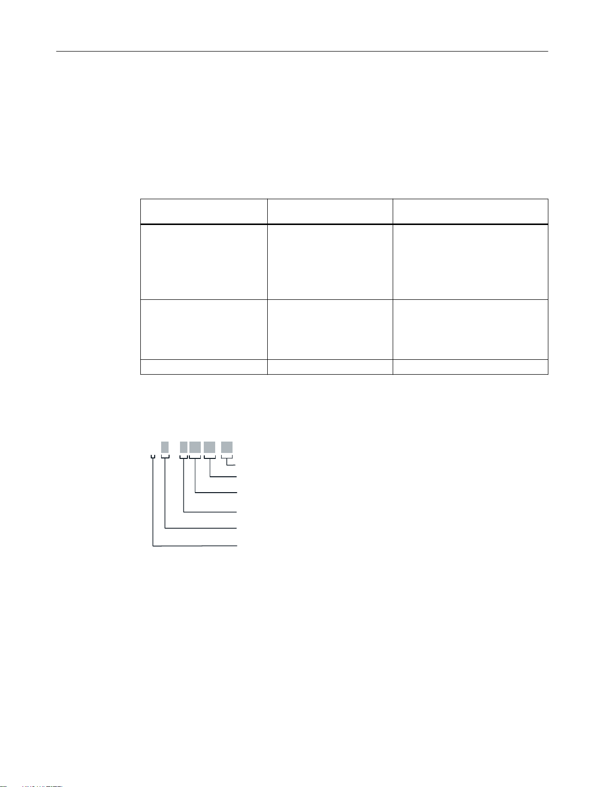
1.2 Type designations
:
06RFNHW
1XPEHURI:/$1LQWHUIDFHV
$FFHVVSRLQW
((&(QKDQFHG(QYLURQPHQWDO&RQGLWLRQ
,(((6WDQGDUG DF
,$,QWHUQDODQWHQQDV
&OLHQW
>@([WHUQDODQWHQQDV
Abbreviations used
The information in the manuals for the SCALANCE W1700 product family often applies to more
than one product variant. In such situations, the designations of the products are shortened to
avoid having to list all the type designations. The following table shows how the abbreviations
relate to the product variants.
Introduction
1.2 Type designations
Product group The designation . . . stands
SCALANCE W1700 ac SCALANCE W1700
Access Points (IP 65) SCALANCE W1780
Client (IP65) SCALANCE W1740
Structure of the type designation
The type designation of the device is made up of several parts that have the following meaning:
Product name
for . . .
● SCALANCE W1788-1 M12
● SCALANCE W1788-2 M12
● SCALANCE W1788-2 M12 EEC
● SCALANCE W1788-2IA M12
● SCALANCE W1748-1 M12
● SCALANCE W1788-1 M12
● SCALANCE W1788-2 M12
● SCALANCE W1788-2 M12 EEC
● SCALANCE W1788-2IA M12
● SCALANCE W1748-1 M12
SCALANCE W1780/W1740 according to IEEE 802.11ac Web Based Management
Configuration Manual, 11/2019, C79000-G8976-C485-03 13
Page 14

Introduction
1.2 Type designations
SCALANCE W1780/W1740 according to IEEE 802.11ac Web Based Management
14 Configuration Manual, 11/2019, C79000-G8976-C485-03
Page 15
Description
Note
Interruption of the WLAN communication
The WLAN communication can be influenced by high frequency interference signals and can
be totally interrupted.
Remember this and take suitable action.
2.1 Network structures
The following article deals with the setup of various network structures using access points.
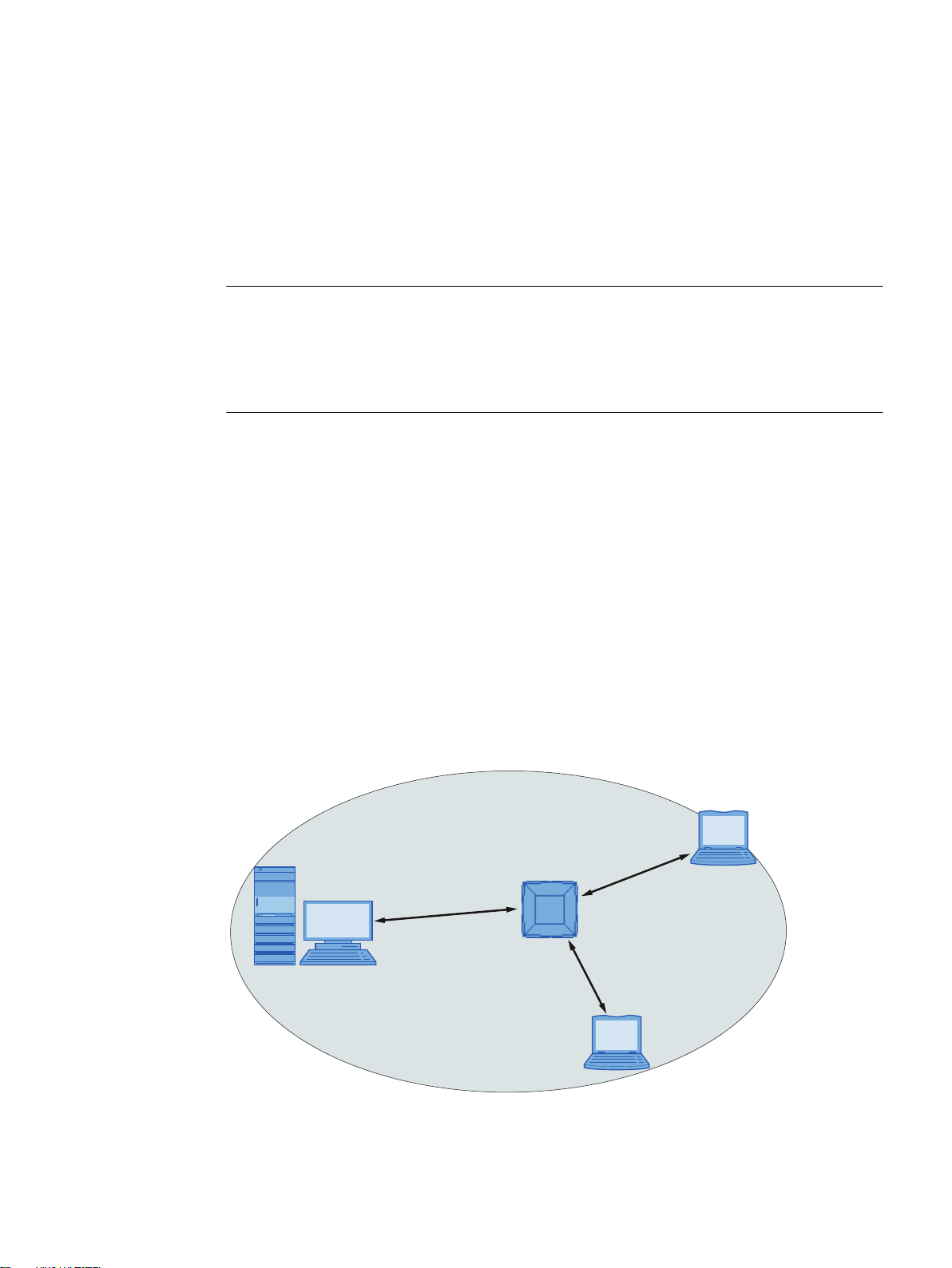
Standalone configuration with access point
This configuration does not require a server and the access point does not have a connection
to a wired Ethernet. Within its transmission range, the access point forwards data from one
WLAN node to another.
2
The wireless network has a unique name. All SCALANCE W devices exchanging data within
this network must be configured with this name.
The gray area in the graphic symbolizes the wireless range of the access point.
SCALANCE W1780/W1740 according to IEEE 802.11ac Web Based Management
Configuration Manual, 11/2019, C79000-G8976-C485-03 15
Page 16
Description
2.1 Network structures
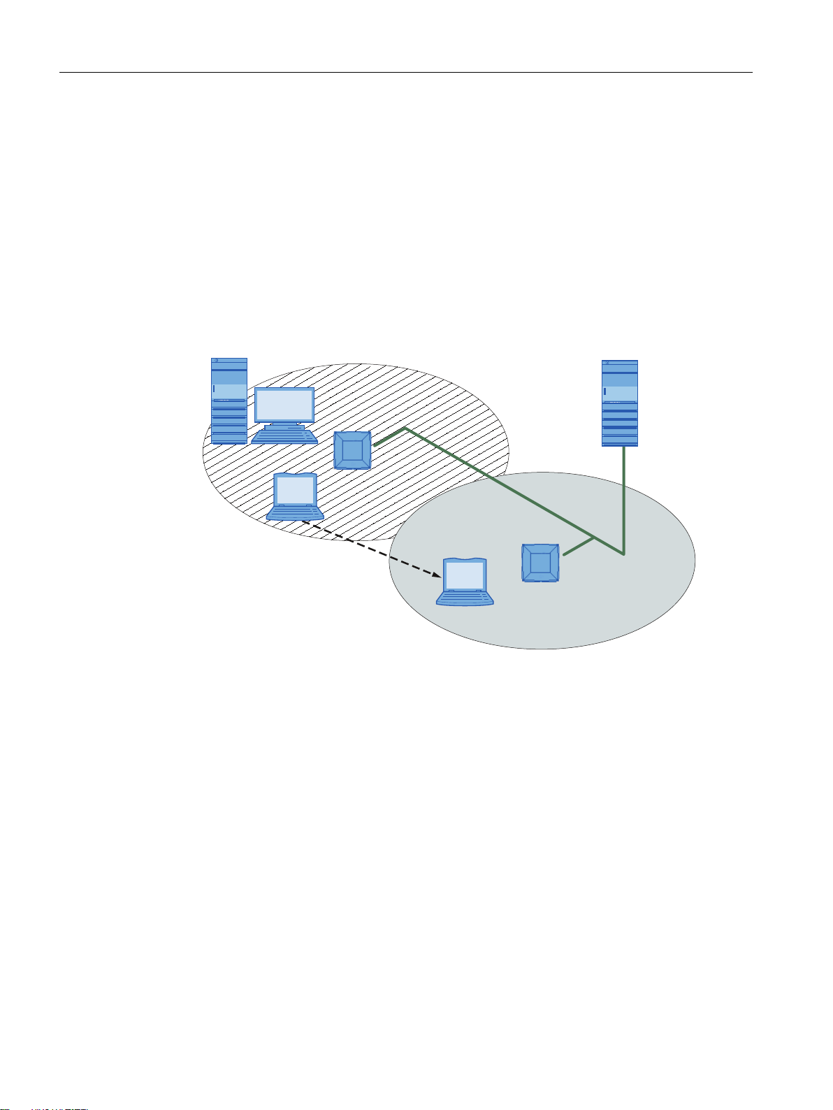
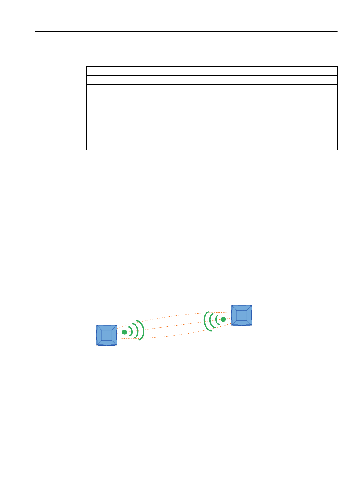
Wireless access to a wired Ethernet network
If one (or more) access points have access to wired Ethernet, the following applications are
possible:
● A single device as gateway:
A wireless network can be connected to a wired network via an access point.
● Span of wireless coverage for the wireless network with several access points:
The access points are all configured with the same unique SSID (network name). All nodes
that want to communicate over this network must also be configured with this SSID.
If a mobile station moves from the area covered by one access point to the area covered by
another access point, the wireless link is maintained (roaming).
The following graphic shows the wireless connection of a mobile station over two wireless
cells (roaming).
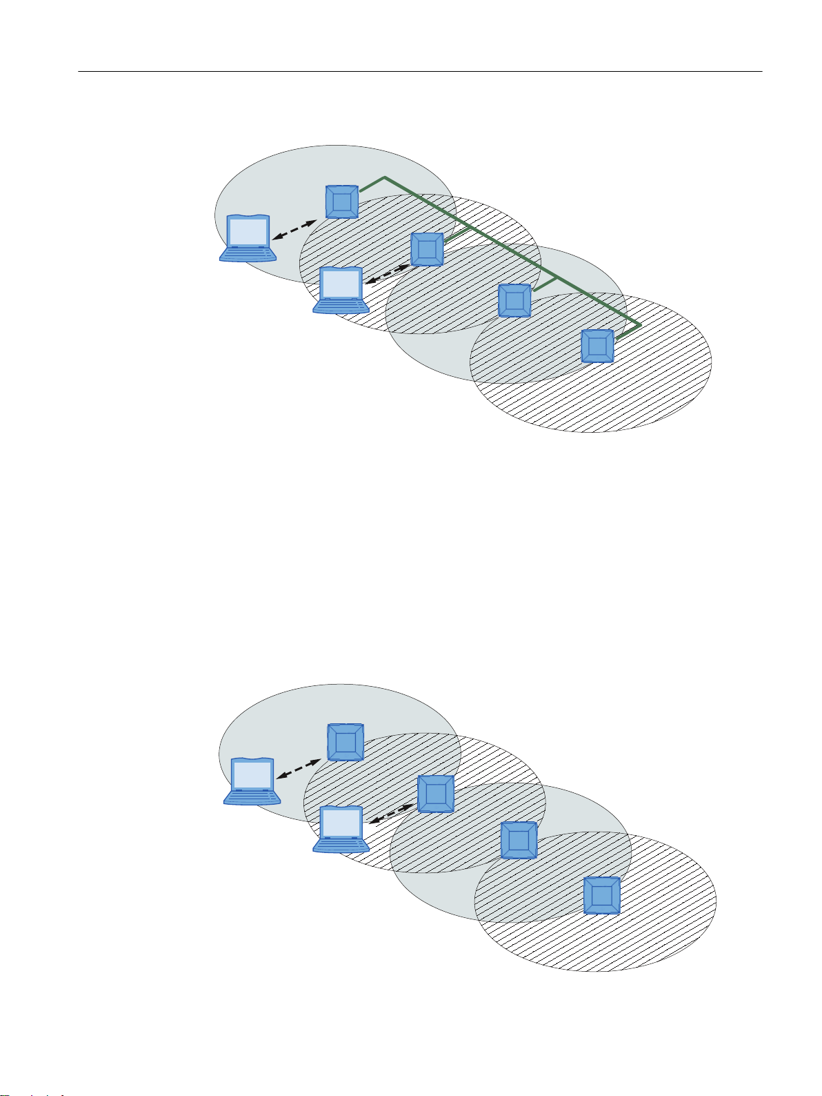
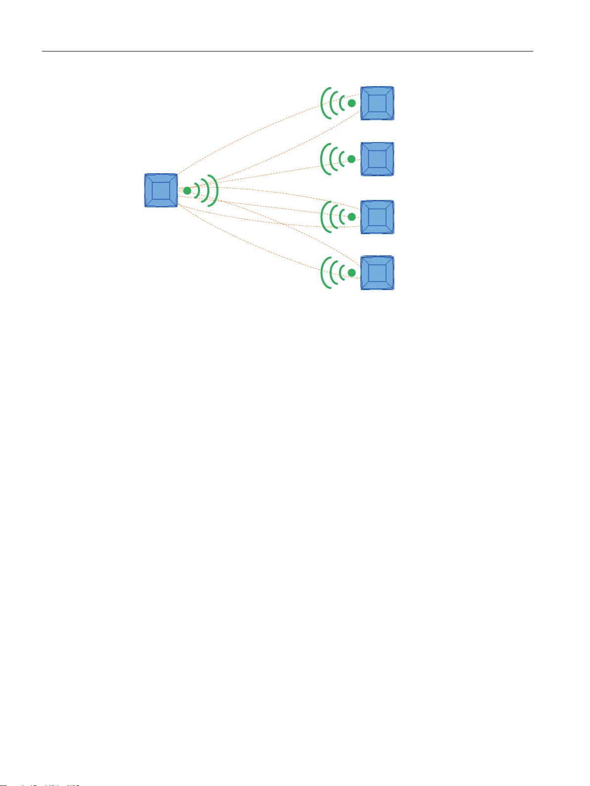
Multichannel configuration
If neighboring access points use the same frequency channel, this can lead to longer response
times due to any collisions that may occur. If the configuration shown in the figure is
implemented as a single-channel system, computers A and B cannot communicate at the same
time with the access points in their wireless cells.
If neighboring access points are set up for different frequencies, this leads to a considerable
improvement in performance. As a result, neighboring wireless cells each have their own
medium available and the delays resulting from time-offset transmission no longer occur.
The channel spacing should be as large as possible; a practical value is 25 MHz. Even in a
multichannel configuration, all access points can be configured with the same network name.
The following graphic shows a multichannel configuration on channels 1 and 2 with four access
points.
SCALANCE W1780/W1740 according to IEEE 802.11ac Web Based Management
16 Configuration Manual, 11/2019, C79000-G8976-C485-03
Page 17
1
1
2
2
A
B
1
1
1
1
A
B
Description
2.1 Network structures
Wireless Distribution System (WDS)
WDS allows direct links between access points and or between access points and other WDScompliant devices. These are used to create a wireless backbone or to connect an individual
access point to a network that cannot be connected directly to the cable infrastructure due to
its location.
Two alternative configurations are possible. The WDS partner can be configured using the
WDS ID or using its MAC address.
The following graphic shows the implementation of WDS with four access points.
SCALANCE W1780/W1740 according to IEEE 802.11ac Web Based Management
Configuration Manual, 11/2019, C79000-G8976-C485-03 17
Page 18

Description
2.2 Possible applications
2.2 Possible applications
Note
The SIMATIC NET WLAN products use OpenSSL.
This is open source code with license conditions (BSD).
Please refer to the current license conditions.
Since the driver includes encryption software, you should also adhere to the appropriate
regulations for your specific country.
Possible applications of the SCALANCE W1788
The SCALANCE W1788 is equipped with up to two Ethernet interfaces and up to two WLAN
interfaces. This makes the device suitable for the following applications:
● The SCALANCE W1788 forwards data within its transmission range from one node to
another without a connection to wired Ethernet being necessary.
● The SCALANCE W1788 can be used as a gateway from a wired to a wireless network.
● The SCALANCE W1788 can be used as a wireless bridge between two networks.
● The SCALANCE W1788 can be used as a bridge between two cells operating at different
frequencies.
● The SCALANCE W1788 comes with an integrated switch and can be networked in a variety
of ways over its two managed Ethernet Gigabit ports.
● The SCALANCE W1788 supports degree of protection IP65, which means it is dust-proof
and protected completely against contact and water jets (nozzle) from any direction.
● The SCALANCE W1788 M12 EEC is suitable for use in harsh environments.
With a SCALANCE W1788 with more than one WLAN interface, you can also implement a
redundant wireless connection to a SCALANCE W1788 with a maximum of two WLAN
interfaces.
SCALANCE W1780/W1740 according to IEEE 802.11ac Web Based Management
18 Configuration Manual, 11/2019, C79000-G8976-C485-03
Page 19

2.3 Product characteristics
Properties of the SCALANCE W1700 devices
● The Ethernet interface supports the following:
– 10 Mbps and 100 Mbps both in full and half duplex
– 1000 Mbps full duplex
– Autocrossing
– Autopolarity
● Operating the WLAN interface in the frequency bands 2.4 GHz and 5 GHz.
● IEEE 802.11ac
High Speed WLAN standard (wireless LAN) with a gross transmission speed of up to 1733
Mbps.
● IEEE 802.11r
Optimization of roaming (Fast BSS Transition)
● The WLAN interface is compatible with the standards IEEE 802.11n.
Description
2.3 Product characteristics
● IEEE 802.11h - Supplement to IEEE 802.11a
In the 802.11h mode, the methods "Transmit Power Control (TPC)" as well as "Dynamic
Frequency Selection (DFS)" are used in the range 5.25 - 5.35 and 5.47 - 5.75 GHz. In some
countries, this allows the frequency subband of 5.47 - 5.725 GHz to be used in the outdoor
area even with higher transmit powers.
TPC is a method of adapting the transmit power.
With DFS, the access point searches for primary users for 60 seconds before starting
communication on the selected channel. During this time the access point does not send
beacons. If signals are found on the channel, the channel is blocked for 30 minutes, the
access point changes channel and repeats the check. Primary users are also searched for
during operation.
● Support of the authentication standards WPA (RADIUS), WPA-PSK, WPA2 (RADIUS),
WPA2-PSK and IEEE 802.1x and the encryption methods WEP, AES and TKIP.
Note
With devices operated in WLAN mode IEEE 802.11n/ac, only WPA2 (WPA2-PSK and
WPA2 Radius) encryption is possible.
● For better transmission via WLAN, the function WMM (wireless multimedia) is enabled. The
frames are evaluated according to their priority and sent prioritized via the WLAN interface.
● Suitable for inclusion of a RADIUS server for authentication.
● Device-related and application-related monitoring of the wireless connection.
SCALANCE W1780/W1740 according to IEEE 802.11ac Web Based Management
Configuration Manual, 11/2019, C79000-G8976-C485-03 19
Page 20

Description
2.4 IEEE 802.11n/ac
● The interoperability of the devices with Wi-Fi devices of other vendors was tested
● Before commissioning the SCALANCE W1700, check the wireless conditions on site. If you
thoroughly.
intend to use Industrial Wireless LAN systems and WirelessHART systems in the 2.4 GHz
band, you will need to plan the use of the channels. At all costs, avoid parallel use of
overlapping frequency ranges. The following overlaps exist with Industrial Wireless LAN
and WirelessHART:
IWLAN channel
IEEE 802.11 b/g/n
1 11 - 16
6 15 - 20
7 16 - 21
11 20 - 25
13 21 - 25
Features of the SCALANCE W1700
Type Number of
WLAN ports
SCALANCE W1788-1 M12 1 4 x exter‐
SCALANCE W1788-2 M12 2 8 x exter‐
SCALANCE W1788-2 M12
EEC
SCALANCE W1788-2IA M12 2 8 x inter‐
SCALANCE W1748-1 M12 1 4 x exter‐
2 8 x exter‐
Antennas Number and
nal
nal
nal
nal
nal
WHART channel
IEEE 802.15.4
type of Ethernet interface
2 x gigabit Ethernet (copper)
1 x PoE
2 x gigabit Ethernet (copper)
1 x PoE
2 x gigabit Ethernet (copper)
1 x PoE
2 x gigabit Ethernet (copper)
1 x PoE
2 x gigabit Ethernet (copper)
1 x PoE
Degree of
protection
IP65 6GK5788-1GY01-0AA0
IP65 6GK5788-2GY01-0AA0
IP65 6GK5788-2GY01-0TA0
IP65 6GK5788-2HY01-0AA0
IP65 6GK5748-1GY01-0AA0
Article number
2.4 IEEE 802.11n/ac
Overview
The IEEE 802.11ac standard is a further development of the IEEE 802.11n standard and is
downward compatible with the standards IEEE 802.11a, IEEE 802.11h and IEEE 802.11n. The
mechanisms of the PHY and MAC layer implemented in the IEEE 802.11n standard have been
improved.
SCALANCE W1780/W1740 according to IEEE 802.11ac Web Based Management
20 Configuration Manual, 11/2019, C79000-G8976-C485-03
Page 21
The following table contains the most important differences.
Single-User
MIMO
Client
IEEE 802.11n IEEE 802.11ac
Frequency band 2.4 GHz and 5 GHz 5 GHz
Channel bandwidth 20 MHz, 40 MHz 20 MHz, 40 MHz, 80 MHz
Spatial streams (data streams) 1 to 4 1 to 8
MIMO Single-User MIMO Multi-User MIMO
Modulation scheme OFDM (BPSK, QPSK, 16-QAM,
MIMO antenna technology
MIMO (Multiple Input - Multiple Output) is based on an intelligent multiple antenna system. The
transmitter and the receiver have several spatially separate antennas. These separated
antennas transmit the data streams (spatial streams) at the same time. Up to four data streams
are possible with IEEE 802.11n and up to eight data streams with IEEE 802.11ac.
64-QAM)
Description
2.4 IEEE 802.11n/ac
Optional: 160 MHz
Up to 4 per client
OFDM (BPSK, QPSK, 16-QAM,
64-QAM, 128-QAM, optional
256-QAM)
The data streams are transmitted over spatially separate paths and return over different paths
due to diffraction, refraction, fading and reflection (multipath propagation). The multipath
propagation means that at the point of reception a complex, space- and time-dependent pattern
results as a total signal made up of the individual signals sent. MIMO uses this unique pattern
by detecting the spatial position of characteristic signals. Here, each spatial position is different
from the neighboring position. The specific characteristics of each sender enable the recipient
to separate several signals from each other.
Single-User MIMO
With Single-User MIMO, the same frame is sent over multiple data streams to a single WLAN
client. A single-user MIMO can operate up to four devices alternately, but only one device at a
time.
Multi-User MIMO
With multi-user MIMO, multiple frames are sent simultaneously to different multi-user MIMO
clients over the same frequency range. A multi-user MIMO therefore supplies up to four multiuser MIMO clients with data simultaneously.
SCALANCE W1780/W1740 according to IEEE 802.11ac Web Based Management
Configuration Manual, 11/2019, C79000-G8976-C485-03 21
Page 22
Multi-User
MIMO
Client 2
Client 3
Client 1
Client 4
Description
2.4 IEEE 802.11n/ac
Spatial mutliplexing
Accelerated guard interval
Frame aggregation
With spatial multiplexing, different information is sent using the same frequency. The data
stream is distributed over n transmitting antennas; in other words, each antenna sends only 1/
n of the data stream. The division of the data stream is restricted by the number of antennas.
The signal is reconstructed at the receiver end. Due to the spatial multiplexing, there is a higher
signal-to-noise ratio and a higher data throughput.
The guard interval prevents different transmissions being mixed together. In
telecommunications, this mixing is also known as intersymbol interference (ISI).
When the send time has elapsed, a send pause (guard interval) must be kept to before the next
transmission begins.
The guard interval of IEEE 802.11a /b/g is 800 ns. IEEE 802.11n/ac can use the reduced guard
interval of 400 ns. You specify the guard interval on the WBM page "AP 802.11n/ac
(Page 237)".
With IEEE 802.11n/ac, it is possible to bundle together individual frames to form one larger
frame, a process referred to as frame aggregation. There are two types of frame aggregation:
● Aggregated MAC Service Data Unit (A-MSDU)
Multiple MSDU frames with the same destination address are bundled and sent as one AMSDU. This reduces the network load. Due to their shorter maximum length, A-MSDUs are
mainly suitable for bundling several shorter frames.
● Aggregated MAC Protocol Data Unit (A-MPDU)
Multiple MPDU frames with the same destination address are bundled and sent as one large
A-MPDU. This allows the total throughput to be increased.
SCALANCE W1780/W1740 according to IEEE 802.11ac Web Based Management
22 Configuration Manual, 11/2019, C79000-G8976-C485-03
Page 23

The SCALANCE W devices support both types of frame aggregation. You make the settings on
the WBM page "AP 802.11n/ac (Page 237)".
Maximum ratio combining (MRC)
In a multiple antenna system, the wireless signals are received by the individual antennas and
combined to form one signal. The MRC method is used to combine the wireless signals. The
MRC method weights the wireless signals according to their signal-to-noise ratio and combines
the wireless signals to form one signal. The signal-to-noise ratio is improved and the error rate
is reduced.
2.5 IEEE 802.11r
During roaming, the WLAN client roams from one access point to the next. A delay time of
several 100 ms can come about at the connection transition.
The following steps can be executed during this time:
● Client searches for a new access point (scanning)
Description
2.6 Requirements for installation and operation
● Logon at a new access point (authentication and association)
● Allow a data connection via the new access point
Shorter delay times are required for time-critical applications, for example, Voice over IP. The
standard IEEE 802.11r contains amendments which optimize roaming and therefore is also
referred to as Fast BSS Transition (FT).
With FT, the WLAN client must not authenticate every time the access point changes. For this
purpose, the access points are grouped into a mobility domain. The WLAN client receives the
mobility domain ID from the first access point to which it logs on. The log-on information is
buffered within the mobility domain. This logon is valid for all members of the mobility domain.
Based on the ID, the WLAN client recognizes whether the access point is a member of the
same mobility domain and can therefore log on without delay. Only WLAN clients with IEEE
802.11r support can use the improved roaming or handover functions.
Requirement
● The access points are members of the same mobility domain
● Only possible with WPA2 encryption (WPA2-PSK and WPA2 RADIUS)
2.6 Requirements for installation and operation
A PG/PC with network connection must be available in order to configure the SCALANCE W
devices. If no DHCP server is available, a PC on which the Primary Setup Tool (PST) is
installed is necessary for the initial assignment of an IP address to the SCALANCE W devices.
For the other configuration settings, a computer with Telnet or a Web browser is necessary.
SCALANCE W1780/W1740 according to IEEE 802.11ac Web Based Management
Configuration Manual, 11/2019, C79000-G8976-C485-03 23
Page 24

Description
2.7 Configuration License PLUG (CLP)
2.7 Configuration License PLUG (CLP)
The PLUG is available in the following variants:
● PLUG Configuration: The exchangeable storage medium only saves the configuration data
of the device.
How it works
NOTICE
Do not remove or insert the PLUG during operation.
A PLUG may only be removed or inserted when the device is turned off.
The device checks whether a PLUG is inserted at one second intervals. If it is detected that the
PLUG has been removed, the device restarts.
If a valid PLUG was inserted in the device, the device changes to a defined error state
following the restart. With SCALANCE W, the available wireless interfaces are deactivated in
this case.
If the device was configured at one time with a PLUG, the device can no longer be used
without this PLUG. To be able to use the device again, reset the device to the factory settings.
PLUG
Devices with CLP slot support the following operating modes:
● Without PLUG
The device saves the configuration data in the internal memory. This mode is active when
no PLUG is inserted.
● With PLUG
If an empty PLUG (as supplied) is inserted in the device, the device automatically backs up
the configuration data on the PLUG during startup. If the PLUG contains a license,
additional functions are also enabled. Changes to the configuration are stored directly on
the PLUG and in the internal memory.
The configuration stored on the PLUG is displayed over the user interfaces.
When an unconfigured device starts up, it automatically adopts the configuration data of the
inserted, written C-PLUG. The prerequisite for this is that the configuration data was written
by a compatible device type.
One exception to this can be the IP configuration if it is set using DHCP and the DHCP server
has not been reconfigured accordingly. Reconfiguration is necessary if you use functions
based on MAC addresses.
Component Description Article number
CLP
Configuration
License PLUG
Exchangeable storage medium for saving configuration
data
SCALANCE CLP 2GB 6GK1900-0UB00-0AA0
SCALANCE CLP EEC 2GB 6GK1900-0UQ00-0AA0
SCALANCE W1780/W1740 according to IEEE 802.11ac Web Based Management
24 Configuration Manual, 11/2019, C79000-G8976-C485-03
Page 25

Component Description Article number
CLP iFeatures Exchangeable storage medium for saving configuration
data and enabling iFeatures
SCALANCE CLP 2GB W1780 6GK5907-8UA00-0AA0
SCALANCE CLP 2GB W1740 6GK5907-4UA00-0AA0
2.8 PRESET PLUG
CLP with preset function (PRESET-PLUG)
With PRESET-PLUG it is possible to install the same configuration and the firmware belonging
to it on several devices.
Note
Using configurations with DHCP
Create a PRESET-PLUG only from device configurations that use DHCP. Otherwise
disruptions will occur in network operation due to multiple identical IP addresses.
Description
2.9 Power over Ethernet (PoE)
You assign fixed IP addresses extra following the basic installation.
In a CLP that was configured as a PRESET-PLUG, the device configuration, user accounts,
certificates and the firmware are stored.
Note
Restore factory defaults and restart with a PRESET PLUG inserted
If you reset a device to the factory defaults, when the device restarts an inserted PRESET
PLUG is formatted and the PRESET PLUG functionality is lost. You then need to create a new
PRESET PLUG.
We recommend that you remove the PRESET PLUG before you reset the device to the factory
settings.
For more detailed information on creating and using a PRESET PLUG refer to the section
Device configuration with PRESET-PLUG (Page 335).
2.9 Power over Ethernet (PoE)
General
"Power over Ethernet" (PoE) is a power supply strategy for network components according to
IEEE with 802.3af or 802.3at.
With PoE, power and data transmission takes place over the used Ethernet cables that connect
the individual network components. This makes an additional power cable unnecessary and
SCALANCE W1780/W1740 according to IEEE 802.11ac Web Based Management
Configuration Manual, 11/2019, C79000-G8976-C485-03 25
Page 26

Description
2.9 Power over Ethernet (PoE)
reduces investment and maintenance costs. PoE can be used with all network components that
require little power (max. 12.95 W).
Which Ethernet connectors of a device are capable of PoE can be found in the operating
instructions of the relevant device.
Cable used for the power supply
● Variant 1 (redundant wires)
In Fast Ethernet, the wire pairs 1, 2 and 3, 6 are used to transfer data. Pairs 4, 5 and 7, 8 are
then used to supply power. If there are only four wires available, the voltage is modulated
onto the wires 1, 2 and 3, 6 (see variant 2). This alternative is suitable for a data transmission
rate of 10/100 Mbps. This type of power supply is not suitable for 1 Gbps since with gigabit
all 8 wires are used for data transfer.
● Variant 2 (phantom power)
With phantom power, the power is supplied over the pairs that are used for data transfer, in
other words, the power is modulated onto the data cable. With Gigabit, all eight wires of the
Ethernet cable are used for data transmission and power supply according to IEEE 802.3at.
With 10/100 Mbps, four wires of the Ethernet cable are used for data transmission and
power supply according to IEEE 802.3af.
Endspan
Midspan
With PoE, there are power generators (Power Source Equipment, PSE) and power consumers
(Power Devices, PD).
Whether a device (power consumer) supports variant 1 and variant 2 or only variant 2 can be
found in the operating instructions of the relevant device.
A power generator (PSE) can supply the power consumer (PD) either over:
● Variant 1 or
● Variant 2 or
● Variant 1 and variant 2.
With endspan, the power is supplied via a switch that can reach a device over an Ethernet
cable. The switch must be capable of PoE, for example a SCALANCE X108PoE, SCALANCE
X308-2M POE, SCALANCE XR552‑12M.
Midspan is used when the switch is not PoE-compliant. The power is supplied by an additional
device between the switch and end device. In this case, only data rates of 10/100 Mbps can be
achieved because the power is supplied on redundant wires.
SCALANCE W1780/W1740 according to IEEE 802.11ac Web Based Management
26 Configuration Manual, 11/2019, C79000-G8976-C485-03
Page 27

Cable lengths
Description
2.9 Power over Ethernet (PoE)
A Siemens power insert can also be used as the interface for the power input. Since a power
insert supports a power supply of 24 VDC, it does not conform with 802.3af or IEEE 802.3at.
The following restrictions relating to the use of power inserts should be noted:
WARNING
Operate the power insert only when the following conditions apply:
● with extra low voltages SELV, PELV complying with IEC 60364-4-41
● in USA/CAN with power supplies complying with NEC class 2
● in USA/CAN, the cabling must meet the requirements of NEC/CEC
● Power load maximum 0.5 A.
Table 2-1 Permitted cable lengths (copper cable - gigabit Ethernet)
Cable type Addition Permitted cable length
IE FC TP Standard Cable GP 4x2
(AWG 24)
IE FC TP Flexible Cable GP 4x2
(AWG24)
IE TP Train Cable GP 4x2
(AWG 24)
with IE FC M12 Plug PRO 4x2 (Xcoded)
with IE FC M12 Plug PRO 4x2 (Xcoded)
with IE FC M12 Plug PRO 4x2 (Xcoded)
0 to 90 m
0 ... 70 m
0 ... 100 m
Table 2-2 Fitting connectors
PIN Color of the
wire
CAT5
1 Yellow Green/white Data Data/power
2 Orange Green Data Data/power
3 White Orange/white Data Data/power
6 Blue Orange Data Data/power
4 Blue Power unused at 10/100 Mbps
5 Blue/white Power unused at 10/100 Mbps
7 Brown/white Power unused at 10/100 Mbps
8 Brown Power unused at 10/100 Mbps
Color of the
wire
CAT6a
LEDs for PoE on the SCALANCE W1700 device
When the SCALANCE W1700 device is supplied by PoE, the green "PoE" LED is lit on the
SCALANCE W1700 device.
Use
Power over un‐
used wires
(10/100 Mbps
only)
Phantom power
SCALANCE W1780/W1740 according to IEEE 802.11ac Web Based Management
Configuration Manual, 11/2019, C79000-G8976-C485-03 27
Page 28

Description
2.9 Power over Ethernet (PoE)
SCALANCE W1780/W1740 according to IEEE 802.11ac Web Based Management
28 Configuration Manual, 11/2019, C79000-G8976-C485-03
Page 29

Security recommendations
To prevent unauthorized access, note the following security recommendations.
General
● You should make regular checks to make sure that the device meets these
recommendations and/or other security guidelines.
● Evaluate your plant as a whole in terms of security. Use a cell protection concept with
suitable products (https://www.industry.siemens.com/topics/global/en/industrial-security/
pages/default.aspx).
● When the internal and external network are disconnected, an attacker cannot access
internal data from the outside. Therefore operate the device only within a protected network
area.
● For communication via non-secure networks use additional devices with VPN functionality
to encrypt and authenticate the communication.
● Terminate management connections correctly (WBM. Telnet, SSH etc.).
Physical access
3
● Restrict physical access to the device to qualified personnel.
The memory card or the PLUG (CLP) contains sensitive data such as certificates, keys etc.
that can be read out and modified.
● Lock unused physical ports on the device. Unused ports can be used to access the system
without authorization.
Software (security functions)
● Keep the firmware up to date. Check regularly for security updates of the product.
You will find information on this on the Internet pages "Industrial Security (https://
www.siemens.com/industrialsecurity)".
● Inform yourself regularly about security advisories and bulletins published by Siemens
ProductCERT (https://www.siemens.com/cert/en/cert-security-advisories.htm).
● Only activate protocols that you really require to use the device.
● Use the security functions such as address translation with NAT (Network Address
Translation) or NAPT (Network Address Port Translation) to protect receiving ports from
access by third parties.
● Restrict access to the device with a firewall or rules in an access control list (ACL - Access
Control List).
● If RADIUS authentication is via remote access, make sure that the communication is within
the secured network area or is via a secure channel.
SCALANCE W1780/W1740 according to IEEE 802.11ac Web Based Management
Configuration Manual, 11/2019, C79000-G8976-C485-03 29
Page 30

Security recommendations
● The option of VLAN structuring provides good protection against DoS attacks and
unauthorized access. Check whether this is practical or useful in your environment.
● Use a central logging server to log changes and access operations. Operate your logging
server within the protected network area and check the logging information regularly.
● Use WPA2/ WPA2-PSK with AES to protect the WLAN. You can find additional information
on this in the section ""Security" menu".
Passwords
● Define rules for the use of devices and assignment of passwords.
● Regularly update passwords and keys to increase security.
● Change all default passwords for users before you operate the device.
● Only use passwords with a high password strength. Avoid weak passwords for example
password1, 123456789, abcdefgh.
● Make sure that all passwords are protected and inaccessible to unauthorized personnel.
● Do not use the same password for different users and systems or after it has expired.
Certificates and keys
● On the device there is a preset SSL certificate with key. Replace this certificate with a self-
● Use a certification authority including key revocation and management to sign certificates.
● Make sure that user-defined private keys are protected and inaccessible to unauthorized
● It is recommended that you use password-protected certificates in the PKCS #12 format
● Verify certificates and fingerprints on the server and client to prevent "man in the middle"
● It is recommended that you use certificates with a key length of at least 2048 bits.
● Change certificates and keys immediately, if there is a suspicion of compromise.
made certificate with key. We recommend that you use a certificate signed either by a
reliable external or by an internal certification authority.
persons.
attacks.
SCALANCE W1780/W1740 according to IEEE 802.11ac Web Based Management
30 Configuration Manual, 11/2019, C79000-G8976-C485-03
Page 31

Secure/non-secure protocols and services
● Avoid and disable non-secure protocols, for example Telnet and TFTP. For historical
reasons, these protocols are still available, however not intended for secure applications.
Use non-secure protocols on the device with caution.
● Check whether use of the following protocols and services is necessary:
– Non-authenticated and unencrypted ports
– LLDP
– Syslog
– DHCP options 66/67
– TFTP
● The following protocols provide secure alternatives:
– SNMPv1/v2c → SNMPv3
Check whether use of SNMPv1/v2c is necessary. SNMPv1/v2c is classified as nonsecure. Use the option of preventing write access. The product provides you with
suitable setting options.
If SNMP is enabled, change the community names. If no unrestricted access is
necessary, restrict access with SNMP.
Use SNMPv3 in conjunction with passwords.
Security recommendations
– HTTP → HTTPS
– Telnet → SSH
– TFTP → SFTP
● Use secure protocols when access to the device is not prevented by physical protection
measures.
● To prevent unauthorized access to the device or network, take suitable protective measures
against non-secure protocols.
● If you require non-secure protocols and services, operate the device only within a protected
network area.
● Restrict the services and protocols available to the outside to a minimum.
● For the DCP function, enable the "Read Only" mode after commissioning.
List of available services
The following is a list of all available services and their ports through which the device can be
accessed.
The table includes the following columns:
● Service
The services that the device supports
● Default port status
This is the status of the port in the delivery state (factory setting).
● Configurable port/service
Indicates whether the port number or the service can be configured via WBM / CLI.
SCALANCE W1780/W1740 according to IEEE 802.11ac Web Based Management
Configuration Manual, 11/2019, C79000-G8976-C485-03 31
Page 32

Security recommendations
● Authentication
Specifies whether the communication partner is authenticated.
If optional, the authentication can be configured as required.
● Encryption
Specifies whether the transfer is encrypted.
If optional, the encryption can be configured as required.
Service Protocol/port num‐
ber
DHCP client UDP/68 Outgoing only -- ✓ -- -DHCP server UDP/67 Closed -- ✓ -- -DNS client TCP/53
UDP/53
EthernetIP TCP/44818,
UDP/2222
UDP/44818
HTTP TCP/80 Open ✓ ✓ ✓ -HTTPS TCP/443 Open ✓ ✓ ✓ ✓
NTP Client UDP/123 Outgoing only ✓ ✓ -- -PROFINET UDP/34964
UDP/49154
UDP/49155
RADIUS UDP/1812 Closed ✓ ✓ ✓ -Remote Capture TCP/2002 Closed -- ✓ -- -SFTP client TCP/22 Closed ✓ ✓ ✓ ✓
SMTP client TCP/25 Closed ✓ ✓ -- -SMTP (secure) - Client TCP/465 Closed ✓ ✓ Optional ✓
SNMPv1/V2c UDP/161 Open ✓ ✓ -- -SNMPv3 UDP/161 Open ✓ ✓ Optional Optional
SNMP traps UDP/162 Outgoing only -- ✓ -- -SNTP Client UDP/123 Outgoing only ✓ ✓ -- -SSH TCP/22 Open ✓ ✓ ✓ ✓
Syslog Client UDP/514 Closed ✓ ✓ -- -Telnet TCP/23 Open ✓ ✓ ✓ -TFTP client UDP/69 Closed ✓ ✓ -- -DCP -- Open -- ✓ -- -LLDP -- Open -- ✓ -- -RSTP -- Open -- ✓ -- -iPRP -- Open -- ✓ -- -MSTP -- Closed -- ✓ -- -IPv6 -- Closed -- ✓ -- -SIMATIC NET TIME -- Closed -- ✓ -- --
Default port
status
Outgoing only -- ✓ -- --
Closed -- ✓ -- --
Open -- ✓ -- --
Configurable Authentication Encryption
Port Service
SCALANCE W1780/W1740 according to IEEE 802.11ac Web Based Management
32 Configuration Manual, 11/2019, C79000-G8976-C485-03
Page 33

Technical basics
4.1 Configuration limits
The following table lists the configuration limits for Web Based Management and the Command
Line Interface of the device.
Depending on your device, some functions are not available.
Configurable function Maximum number
System Syslog server 3
DNS server manual (IPv4/IPv6) 3
SMTP server 2
SNMPv1 trap recipient 10
SNTP server 2
NTP server 1
DHCP pools 1
IPv4 addresses managed by the DHCP server
(dynamic + static)
DHCP static assignments per DHCP pool 20
DHCP options 20
Interfaces Force destination addresses for roaming 10
Connected clients per VAP interface
Layer 2 Virtual LANs (port-based, including VLAN 1) 24
Multiple Spanning Tree instances 16
Layer 3 IP interface 2
DHCP client 1
Security IP addresses from RADIUS servers
Management ACLs (access rules for manage‐
ment)
User roles 32
User groups 32
Users 30
4
learned (IPv4/IPv6) 2
in total 7
100
● 255 with security "Open
System"
● 128 with Security "WPA /
WPA2 / Shared Key"
1 subnet per IP interface
● AAA: 4
● WLAN: 2
10
(incl. the predefined roles)
(incl. the predefined users)
SCALANCE W1780/W1740 according to IEEE 802.11ac Web Based Management
Configuration Manual, 11/2019, C79000-G8976-C485-03 33
Page 34

Technical basics
4.2 Interfaces and system functions
4.2 Interfaces and system functions
Availability of the interfaces
The following table shows the availability of the physical and logical interfaces. Note that in this
table all interfaces are listed. Depending on the system function, some interfaces are not
available. On the WBM pages you can only select the available interfaces.
We reserve the right to make technical changes.
Client Access point
W1748-1 M12 W1788-1 M12 W1788-2 M12
Wireless interface
(WLAN)
LAN interface P1 LAN
VAP interface - VAP 1.Y
WDS interface - WDS 1.Y
VLAN 24 24 24
WLAN 1
P2 LAN PoE
WLAN 1
P1 LAN
P2 LAN PoE
Y = 1 ... 8
Y = 1 ... 8
W1788-2 M12 EEC
W1788-2IA M12
WLAN 1
WLAN 2
P1 LAN
P2 LAN PoE
VAP X.Y
X = 1 ... 2
Y = 1 ... 8
WDS X.Y
X = 1 ... 2
Y = 1 ... 8
Availability of the system functions
The following table shows the availability of the system functions on the devices.
SCALANCE W1780/W1740 according to IEEE 802.11ac Web Based Management
34 Configuration Manual, 11/2019, C79000-G8976-C485-03
Page 35

Technical basics
4.2 Interfaces and system functions
We reserve the right to make technical changes.
Access point mode Client devices
Access points in client mode
Information Security Inter AP blocking ✓ -
WLAN Overview AP ✓ -
Client List ✓ WDS list ✓ Overlap AP ✓ Force Roaming ✓ ✓
Overview Client - ✓
Available AP - ✓
IP Mapping - ✓
WLAN Sta‐
tistics
WLAN
iFeatures
System PROFINET ✓ -✓
DHCP DHCP Client ✓ ✓
Interfaces WLAN Basic ✓ -✓
Layer 3
(IPv4 / IPv6)
Subnets - ✓
Faults ✓ ✓
Management Sent ✓ ✓
Management Received ✓ ✓
Data Sent ✓ ✓
Data Received ✓ ✓
iPRP ✓ -
EtherNet/IP ✓ ✓
DHCP Server ✓ DHCP Options ✓ Static Leases ✓ -
Advanced ✓ ✓
Antennas ✓ ✓
Allowed Channels ✓ ✓
802.11n/ac ✓ ✓
AP ✓ AP WDS ✓ Client 802.11a/b/g data rates - ✓
Client 802.11n data rates - ✓
Force Roaming ✓ ✓
Signal recorder - ✓
Static route - ✓
SCALANCE W1780/W1740 according to IEEE 802.11ac Web Based Management
Configuration Manual, 11/2019, C79000-G8976-C485-03 35
Page 36

Technical basics
4.3 EtherNet/IP
Access point mode Client devices
Access points in client mode
Security WLAN Basic ✓ ✓
AP Communication ✓ AP RADIUS Authenticator ✓ Client RADIUS Supplicant - ✓
802.11r ✓ Keys ✓ ✓
Inter AP
Blocking
iFeatures iPRP
1) Only with CLP iFeatures, see section "Configuration License PLUG (CLP)".
1)
Basic ✓ Allowed Addresses ✓ -
✓ ✓
Support of IPv6
The following system functions do not support IPv6 addresses:
● Inter AP blocking
● Force roaming
4.3 EtherNet/IP
EtherNet/IP
EtherNet/IP (Ethernet/Industrial Protocol) is an open industry standard for industrial real-time
Ethernet based on TCP/IP and UDP/IP. With EtherNet/IP, Ethernet is expanded by the
Common Industrial Protocol (CIP) at the application layer. In EtherNet/IP, the lower layers of
the OSI reference model are adopted by Ethernet with the physical, network and transport
functions.
You configure EtherNet/IP in "System > EtherNet/IP (Page 209)".
Common Industrial Protocol
The Common Industrial Protocol (CIP) is an application protocol for automation that supports
transition of the field buses in Industrial Ethernet and in IP networks. This industry protocol is
used by field buses/industrial networks such as DeviceNet, ControlNet and EtherNet/IP at the
application layer as an interface between the deterministic fieldbus world and the automation
application (controller, I/O, HMI, OPC, ...). The CIP is located above the transport layer and
expands the pure transport services with communications services for automation engineering.
These include services for cyclic, time-critical and event-controlled data traffic. CIP
distinguishes between time-critical I/O messages (implicit messages) and individual query/
response frames for configuration and data acquisition (explicit messages). CIP is objectoriented; all data "visible" from the outside is accessible in the form of objects. CIP has a
common configuration basis: EDS (Electronic Data Sheet).
SCALANCE W1780/W1740 according to IEEE 802.11ac Web Based Management
36 Configuration Manual, 11/2019, C79000-G8976-C485-03
Page 37

Electronic Data Sheet
Electronic Data Sheet (EDS) is an electronic datasheet for describing devices.
The EDS required for EtherNet/IP operation can be found in "System > Load&Save
(Page 152)".
4.4 PROFINET
PROFINET
PROFINET is an open standard (IEC 61158/61784) for industrial automation based on
Industrial Ethernet. PROFINET uses existing IT standards and allows end-to-end
communication from the field level to the management level as well as plant-wide engineering.
PROFINET also has the following features:
● Use of TCP/IP
● Automation of applications with real-time requirements
Technical basics
4.5 VLAN
– Real-Time (RT) communication
– Isochronous Real-Time (IRT) communication
● Seamless integration of fieldbus systems
You configure PROFINET in "System > PROFINET (Page 208)".
PROFINET IO
Within the framework of PROFINET, PROFINET IO is a communications concept for
implementing modular, distributed applications. PROFINET IO is implemented by the
PROFINET standard for programmable controllers (IEC 61158-x-10).
4.5 VLAN
Network definition regardless of the spatial location of the nodes
VLAN (Virtual Local Area Network) divides a physical network into several logical networks that
are shielded from each other. Here, devices are grouped together to form logical groups. Only
nodes of the same VLAN can address each other. Since multicast and broadcast frames are
only forwarded within the particular VLAN, they are also known as broadcast domains.
The particular advantage of VLANs is the reduced network load for the nodes and network
segments of other VLANs.
For the identifier which frame is assigned to which VLAN, the frame is expanded by 4 bytes
(VLAN tagging). Apart from the VLAN-ID this expansion also includes priority information.
SCALANCE W1780/W1740 according to IEEE 802.11ac Web Based Management
Configuration Manual, 11/2019, C79000-G8976-C485-03 37
Page 38

Technical basics
4.6 SNMP
Options for the VLAN assignment
There are various options for the assignment to VLANs:
● Port-based VLAN
Each port of a device is assigned a VLAN ID. You configure port-based VLAN in "Layer 2 >
VLAN (Page 261)".
● Protocol-based VLAN
Each port of a device is assigned a protocol group.
● Subnet-based VLAN
The IP address of the device is assigned a VLAN ID.
Doubly tagged frame (Q-in-Q)
There are devices e.g. SCALANCE XR500 that support the Q-in-Q function. With the Q-in-Q
function the incoming data traffic is treated as if it were untagged. With frames that are already
tagged ①, this means they are expanded by a second VLAN tag, the outer VLAN tag ②.
When a SCALANCE W device receives a doubly tagged frame, it uses the VLAN ID from the
outer VLAN tag ② and the priority information from the inner VLAN tag ①. The frame is then
forwarded to the relevant VLAN.
4.6 SNMP
Introduction
With the aid of the Simple Network Management Protocol (SNMP), you monitor and control
network components from a central station, for example routers or switches. SNMP controls the
communication between the monitored devices and the monitoring station.
Tasks of SNMP:
● Monitoring of network components
● Remote control and remote parameter assignment of network components
● Error detection and error notification
In versions v1 and v2c, SNMP has no security mechanisms. Each user in the network can
access data and also change parameter assignments using suitable software.
For the simple control of access rights without security aspects, community strings are used.
The community string is transferred along with the query. If the community string is correct, the
SNMP agent responds and sends the requested data. If the community string is not correct, the
SNMP agent discards the query. Define different community strings for read and write
permissions. The community strings are transferred in plain text.
SCALANCE W1780/W1740 according to IEEE 802.11ac Web Based Management
38 Configuration Manual, 11/2019, C79000-G8976-C485-03
Page 39

Technical basics
4.6 SNMP
Standard values of the community strings:
● public
has only read permissions
● private
has read and write permissions
Note
Because the SNMP community strings are used for access protection, do not use the
standard values "public" or "private". Change these values following the initial
commissioning.
Further simple protection mechanisms at the device level:
● Allowed Host
The IP addresses of the monitoring systems are known to the monitored system.
● Read Only
If you assign "Read Only" to a monitored device, monitoring stations can only read out data
but cannot modify it.
SNMP data packets are not encrypted and can easily be read by others.
The central station is also known as the management station. An SNMP agent is installed on
the devices to be monitored with which the management station exchanges data.
The management station sends data packets of the following type:
● GET
Request for a data record from the SNMP agent
● GETNEXT
Calls up the next data record.
● GETBULK (available as of SNMPv2c)
Requests multiple data records at one time, for example several rows of a table.
● SET
Contains parameter assignment data for the relevant device.
The SNMP agent sends data packets of the following type:
● RESPONSE
The SNMP agent returns the data requested by the manager.
● TRAP
If a certain event occurs, the SNMP agent itself sends traps.
SNMPv1/v2c/v3 use UDP (User Datagram Protocol) and use the UDP ports 161 and 162. The
data is described in a Management Information Base (MIB).
SNMPv3
Compared with the previous versions SNMPv1 and SNMPv2c, SNMPv3 introduces an
extensive security concept.
SCALANCE W1780/W1740 according to IEEE 802.11ac Web Based Management
Configuration Manual, 11/2019, C79000-G8976-C485-03 39
Page 40

Technical basics
4.7 Spanning Tree
SNMPv3 supports:
● Fully encrypted user authentication
● Encryption of the entire data traffic
● Access control of the MIB objects at the user/group level
With the introduction of SNMPv3, you can no longer transfer user configurations to other
devices without taking special action, e.g. by loading a configuration file.
According to the standard, the SNMPv3 protocol uses a unique SNMP engine ID as an internal
identifier for an SNMP agent. This ID must be unique in the network. It is used to authenticate
access data of SNMPv3 users and to encrypt it.
Depending on whether you have enabled or disabled the “SNMPv3 User Migration” function,
the SNMP engine ID is generated differently.
Restriction when using the function
Use the "SNMPv3 User Migration" function only to transfer configured SNMPv3 users to a
substitute device when replacing a device.
Do not use the function to transfer configured SNMPv3 users to multiple devices. If you load a
configuration with created SNMPv3 users on several devices, these devices use the same
SNMP engine ID. If you use these devices in the same network, your configuration contradicts
the SNMP standard.
Compatibility with predecessor products
You can only transfer SNMPv3 users to a different device if you have created the users as
migratable users. To create a migratable user the "SNMPv3 User Migration" function must be
activated when you create the user.
4.7 Spanning Tree
Avoiding loops
The Spanning Tree algorithm detects redundant physical network structures and prevents the
formation of loops by disabling redundant paths. It evaluates the distance and performance of
a connection or bases the decisions on settings made by the user. Data is then exchanged only
over the remaining connection paths.
If the preferred data path fails, the Spanning Tree algorithm then searches for the most efficient
path possible with the remaining nodes.
Root bridge and bridge priority
The identification of the most efficient connection is always related to the root bridge, a network
component that can be considered as a root element of a tree-like network structure. With the
"Bridge Priority" parameter, you can influence the selection of the root bridge. The computer
with the lowest value set for this parameter automatically becomes the root bridge. If two
computers have the same priority value, the computer with the lower MAC address becomes
the root bridge.
SCALANCE W1780/W1740 according to IEEE 802.11ac Web Based Management
40 Configuration Manual, 11/2019, C79000-G8976-C485-03
Page 41

Response to changes in the network topology
If nodes are added to a network or drop out of the network, this may affect the optimum path
selection for data packets. To be able to respond to such changes, the root bridge sends
configuration messages (BPDUs) at regular intervals. You can set the interval between two
configuration messages with the "Hello Time" parameter.
Keeping configuration information up to date
With the "Max Age" parameter, you set the maximum age of configuration information. If a
bridge has information that is older than the time set in Max Age, it discards the message and
initiates recalculation of the paths.
New configuration data is not used immediately by a bridge but only after the period specified
in the "Forward Delay" parameter. This ensures that operation is started with the new topology
only after all the bridges have the required information.
4.7.1 RSTP, MSTP, CIST
Technical basics
4.7 Spanning Tree
Rapid Spanning Tree Protocol (RSTP)
One disadvantage of STP is that if there is a disruption or a device fails, the network needs to
reconfigure itself: The devices start to negotiate new paths only when the interruption occurs.
This can take up to 30 seconds. Fur this reason, STP was expanded to create the "Rapid
Spanning Tree Protocol" (RSTP, IEEE 802.1w). This differs from STP essentially in that the
devices are already collecting information about alternative routes during normal operation and
do not need to gather this information after a disruption has occurred. This means that the
reconfiguration time for an RSTP controlled network can be reduced to a few seconds.
This is achieved by using the following functions:
● Edge ports (end node port)
Edge ports are ports connected to an end device.
A port that is defined as an edge port is activated immediately after connection
establishment. If a spanning tree BPDU is received at an edge port, the port loses its role as
edge port and it takes part in (R)STP again. If no further BPDU is received after a certain
time has elapsed (3 x hello time), the port returns to the edge port status.
● Point-to-point (direct communication between two neighboring devices)
By directly linking the devices, a status change (reconfiguration of the ports) can be made
without any delays.
● Alternate port (substitute for the root port)
A substitute for the root port is configured. If the connection to the root bridge is lost, the
device can establish a connection over the alternate port without any delay due to
reconfiguration.
SCALANCE W1780/W1740 according to IEEE 802.11ac Web Based Management
Configuration Manual, 11/2019, C79000-G8976-C485-03 41
Page 42

Technical basics
4.8 User management
● Reaction to events
Rapid spanning tree reacts to events, for example an aborted connection, without delay.
There is no waiting for timers as in spanning tree.
● Counter for the maximum bridge hops
The number of bridge hops a package is allowed to make before it automatically becomes
invalid.
In principle, therefore with rapid spanning tree, alternatives for many parameters are
preconfigured and certain properties of the network structure taken into account to reduce the
reconfiguration time.
Multiple Spanning Tree Protocol (MSTP)
The Multiple Spanning Tree Protocol (MSTP) is a further development of the Rapid Spanning
Tree Protocol. Among other things, it provides the option of operating several RSTP instances
within different VLANs or VLAN groups and, for example, making paths available within the
individual VLANs that the single Rapid Spanning Tree Protocol would globally block.
Common and Internal Spanning Tree (CIST)
CIST identifies the internal instance used by the switch that is comparable in principle with an
internal RSTP instance.
4.8 User management
Overview of user management
Access to the device is managed by configurable user settings. Set up users with a password
for authentication. Assign a role with suitable rights to the users.
The authentication of users can either be performed locally by the device or by an external
RADIUS server. You configure how the authentication is handled on the "Security > AAA >
General" page.
Local logon
The local logging on of users by the device runs as follows:
1. The user logs on with user name and password on the device.
2. The device checks whether an entry exists for the user.
→ If an entry exists, the user is logged in with the rights of the associated role.
→ If no corresponding entry exists, the user is denied access.
Login via an external RADIUS server
RADIUS (Remote Authentication Dial-In User Service) is a protocol for authenticating and
authorizing users by servers on which user data can be stored centrally.
SCALANCE W1780/W1740 according to IEEE 802.11ac Web Based Management
42 Configuration Manual, 11/2019, C79000-G8976-C485-03
Page 43

Technical basics
4.8 User management
Depending on the RADIUS authorization mode you have selected on the "Security > AAA >
RADIUS Client" page, the device evaluates different information of the RADIUS server.
RADIUS authorization mode "Standard"
If you have set the authorization mode "conventional", the authentication of users via a RADIUS
server runs as follows:
1. The user logs on with user name and password on the device.
2. The device sends an authentication request with the login data to the RADIUS server.
3. The RADIUS server runs a check and signals the result back to the device.
– The RADIUS server reports a successful authentication and returns the value
"Administrative User" to the device for the attribute "Service Type".
→ The user is logged in with administrator rights.
– The RADIUS server reports a successful authentication and returns a different or even
no value to the device for the attribute "Service Type".
→ The user is logged in with read rights.
– The RADIUS server reports a failed authentication to the device:
→ The user is denied access.
RADIUS authorization mode "SiemensVSA"
Requirement
For the RADIUS authorization mode "Siemens VSA" the following needs to be set on the
RADIUS server:
● Manufacturer code: 4196
● Attribute number: 1
● Attribute format: Character string (group name)
Procedure
SCALANCE W1780/W1740 according to IEEE 802.11ac Web Based Management
Configuration Manual, 11/2019, C79000-G8976-C485-03 43
Page 44

Technical basics
4.9 iFeatures
If you have set the authorization mode "SiemensVSA", the authentication of users via a
RADIUS server runs as follows:
1. The user logs on with user name and password on the device.
2. The device sends an authentication request with the login data to the RADIUS server.
3. The RADIUS server runs a check and signals the result back to the device.
Case A: The RADIUS server reports a successful authentication and returns the group
assigned to the user to the device.
– The group is known on the device and the user is not entered in the table "External User
Accounts"
→ The user is logged in with the rights of the assigned group.
– The group is known on the device and the user is entered in the table "External User
Accounts"
→ The user is assigned the role with the higher rights and logged in with these rights.
– The group is not known on the device and the user is entered in the table "External User
Accounts"
→ The user is logged in with the rights of the role linked to the user account.
– The group is not known on the device and the user is not entered in the table "External
User Accounts"
→ The user is logged in with the rights of the role "Default".
Case B: The RADIUS server reports a successful authentication but does not return a group
to the device.
– The user is entered in the table "External User Accounts":
→ The user is logged in with the rights of the linked role "".
– The user is not entered in the table "External User Accounts":
→ The user is logged in with the rights of the role "Default".
Case C: The RADIUS server reports a failed authentication to the device:
– The user is denied access.
4.9 iFeatures
4.9.1 iPRP
The "Parallel Redundancy Protocol" (PRP) is a redundancy protocol for cabled networks. It is
defined in Part 3 of the IEC 62439 standard.
With the "industrial Parallel Redundancy Protocol" (iPRP) the PRP technology can be used in
wireless networks. This improves the availability of wireless communication.
SCALANCE W1780/W1740 according to IEEE 802.11ac Web Based Management
44 Configuration Manual, 11/2019, C79000-G8976-C485-03
Page 45

How it works
,QGXVWULDO(WKHUQHW
6LQJOH$WWDFKHG1RGH
6$1
5HGXQGDQF\%R[
5HG%R[
9/$19/$19/$19/$1
$FFHVV3RLQW$3
:/$1
9$3!9/$1353$
9$3!9/$1353%
39/$19/$1
&OLHQW$
:/$1!9/$1353$
39/$19/$1
&OLHQW%
:/$1!9/$1353%
39/$19/$1
9/$19/$1
6LQJOH$WWDFKHG1RGH
6$1
5HGXQGDQF\%R[
5HG%R[
353%
353$
353%353$
9/$1353%9/$1353$
9/$19/$1
$FFHVV3RLQW$3
:/$1
9$3!9/$1353$
9$3!9/$1353%
39/$19/$1
$FFHVV3RLQW$3
:/$1
9$3!9/$1353$
9$3!9/$1353%
39/$19/$1
Technical basics
4.9 iFeatures
A PRP network consists of two completely independent networks. If one network is disrupted,
the frames are sent without interruption/reconfiguration via the parallel redundant network. To
achieve this the Ethernet frames are sent to the recipient in duplicate via both networks.
Devices capable of PRP have at least two separate Ethernet interfaces that are connected to
independent networks.
With devices not capable of PRP a redundancy box (RedBox) is connected upstream. This
allows access for so-called Single Attached Nodes (SAN) to PRP networks. The RedBox
duplicates every Ethernet frame to be sent and adds a PRP trailer to the frame that among other
things contains a sequence number. The RedBox simultaneously sends a copy of the frame to
the PRP A and PRP B network. At the receiving end the duplicate frame is discarded by the
RedBox. For this the RedBox requires certain transfer times designed for Ethernet networks.
For this reason using PRP in WLAN networks results in duplicate and delayed frames.
With iPRP, this problem is solved and the use of PRP in WLAN with SCALANCE W devices
becomes possible
SCALANCE W1780/W1740 according to IEEE 802.11ac Web Based Management
Configuration Manual, 11/2019, C79000-G8976-C485-03 45
Page 46

Technical basics
4.9 iFeatures
The access points (AP 1, AP 2 and AP 3) and the RedBox at the AP end are connected to each
other via a switch. PRP network A und B are separated from each other via VLANs.
If SAN1 sends a frame to SAN2, the frame is duplicated by the RedBox at the AP end and the
two redundant frames are transferred via the switch to the access points. Via the two different
wireless paths the redundant PRP frames are transferred to the RedBox at the client end. The
clients are also connected to their RedBox via a switch. This forwards the first PRP frame to
arrive to SAN2 and discards the second one.
Note
On the interfaces of the switches to the SCALANCE W devices, only the VLANs that are also
set on the VAP or WLAN interfaces of the SCALANCE W devices may be configured.
With iPRP the redundant partners (here: AP1 and AP3 or client A and client B) communicate
with each other via a switch to prevent the two redundant PRP frames from arriving at the
RedBox with too great a time difference.
If for example the communication between AP1 and client A is very slow, the slower frame is
discarded at the receiving end.
You configure iPRP in "iFeatures > iPRP (Page 329)".
Requirement
● iPRP can only be used with the CLP iFeatures (Page 24).
● The base bridge mode "802.1Q VLAN Bridge" is set.
● The VLANs have been created.
● Access point mode: The VAP interface is enabled.
● Client mode: In MAC mode "Layer 2 Tunnel" is set.
● Depending on the configuration the clients can communicate with every access point.
SCALANCE W1780/W1740 according to IEEE 802.11ac Web Based Management
46 Configuration Manual, 11/2019, C79000-G8976-C485-03
Page 47

IP addresses
5.1 IPv4 / IPv6
What are the essential differences?
IPv4 IPv6
IP configuration
Available IP addresses 32-bit: 4, 29 * 109 address‐es128-bit: 3, 4 * 1038 addresses
● DHCP server
● Manual
● Stateless Address Autoconfiguration (SLAAC): Stateless
autoconfiguration using NDP (Neighbor Discovery
Protocol)
– Creates a link local address for every interface that
does not require a router on the link.
– Checks the uniqueness of the address on the link that
requires no router on the link.
– Specifies whether the global addresses are obtained
via a stateless mechanism, a stateful mechanism or via
both mechanisms. (Requires a router on the link.)
● Manual
● DHCPv6 (stateful)
5
Address format Decimal: 192.168.1.1
with port: 192.168.1.1:20
Loopback 127.0.0.1 ::1
IP addresses of the interface 4 IP addresses Multiple IP addresses
Header
Fragmentation Host and router Only endpoint of the communication
Quality of service Type of Service (ToS) for
Types of frame Broadcast, multicast, uni‐
● Checksum
● Variable length
● Fragmentation in the
header
● No security
prioritization
cast
Hexadecimal: 2a00:ad80::0123
with port: [2a00:ad80::0123]:20
● LLA: A link local address (formed automatically) fe80::/128
per interface
● ULA: Several unique local unicast addresses per interface
● GUA: Several global unicast addresses per interface
● Checking at a higher layer
● Fixed size
● Fragmentation in the extension header
The prioritization is specified in the header field "Traffic Class".
Multicast, unicast, anycast
SCALANCE W1780/W1740 according to IEEE 802.11ac Web Based Management
Configuration Manual, 11/2019, C79000-G8976-C485-03 47
Page 48

IP addresses
5.1 IPv4 / IPv6
IPv4 IPv6
Identification of DHCP clients/
server
DHCP via UDP with broadcast via UDP with unicast
Resolution of IP addresses in
hardware addresses
Client ID:
● MAC address
● DHCP client ID
● System name
● PROFINET station
name
● IAID and DUID
ARP (Address Resolution
Protocol)
DUID + IAID(s) = exactly one interface of the host
DUID = DHCP unique identifier
Unique identifier of server and clients
IAID = Identity Association Identifier
At least one per interface is generated by the client and re‐
mains unchanged when the DHCP client restarts
Three methods of obtaining the DUID
● DUID-LLT
● DUID-EN
● DUID-LL
RFC 3315, RFC 3363
Stateful DHCPv6
Stateful configuration in which the IPv6 address and the con‐
figuration settings are transferred.
Four DHVPv6 messages are exchanged between client and
server:
1. SOLICIT:
Sent by the DHCPv6 client to localize DHCPv6 servers.
2. ADVERTISE
The available DHCPv6 servers reply to this.
3. REQUEST
The DHCPv6 client requests an IPv6 address and the
configuration settings from the DHCPv6 server.
4. REPLY
The DHCPv6 server sends the IPv6 address and the
configuration settings.
If the client and server support the function "Rapid commit" the
procedure is shortened to two DHCPv6 messages SOLICIT
and REPLY .
Stateless DHCPv6
In stateless DHCPv6, only the configuration settings are trans‐
ferred.
Prefix delegation
The DHCPv6 server delegates the distribution of IPv6 prefixes
to the DHCPv6 client. The DHCPv6 client is also known as PD
router.
NDP (Neighbor Discovery Protocol)
SCALANCE W1780/W1740 according to IEEE 802.11ac Web Based Management
48 Configuration Manual, 11/2019, C79000-G8976-C485-03
Page 49

5.2 IPv4 address
5.2.1 Structure of an IPv4 address
The IPv4 address consists of 4 decimal numbers separated by a dot. Each decimal number can
have a value from 0 to 255.
Example: 192.168.16.2
The IPv4 address is composed of:
● Address of the (sub)network
● The address of the node (generally also called end node, host or network node)
Subnet mask
The subnet mask consists of four decimal numbers with the range from 0 to 255, each number
separated by a period; example: 255.255.0.0
The binary representation of the 4 subnet mask decimal numbers must contain a series of
consecutive 1s from the left and a series of consecutive 0s from the right.
IP addresses
5.2 IPv4 address
The "1" values determine the network address within the IPv4 address. The "0" values
determine the device address within the IPv4 address.
Example:
Correct values
255.255.0.0 D = 1111 1111.1111 1111.0000 0000.0000 0000 B
255.255.128.0 D = 1111 1111.1111 1111.1000 0000.0000 0000 B
255.254.0.0 D = 1111 1111.1111 1110.0000 0000.0000.0000 B
Incorrect value:
255.255.1.0 D = 1111 1111.1111 1111.0000 0001.0000 0000 B
Subnet mask: 255.255.0.0 = 11111111.11111111.00000000.00000000
In the example for the IP address mentioned above, the subnet mask shown here has the
following meaning:
The first 2 bytes of the IP address determine the subnet - i.e. 192.168. The last two bytes
address the device, i.e. 16.2.
The following applies in general:
● The network address results from the AND combination of IPv4 address and subnet mask.
● The device address results from the AND-NOT combination of IPv4 address and subnet
mask.
SCALANCE W1780/W1740 according to IEEE 802.11ac Web Based Management
Configuration Manual, 11/2019, C79000-G8976-C485-03 49
Page 50

IP addresses
5.2 IPv4 address
Classless Inter-Domain Routing (CIDR)
CIDR is a method that groups several IPv4 addresses into an address range by representing
an IPv4 address combined with its subnet mask. To do this, a suffix is appended to the IPv4
address that specifies the number of bits of the network mask set to 1. Using the CIDR notation,
routing tables can be reduced in size and the available address ranges put to better use.
Example:
IPv4 address 192.168.0.0 with subnet mask 255.255.255.0
The network part of the address covers 3 x 8 bits in binary representation; in other words 24 bits.
This results in the CIDR notation 192.168.0.0/24.
The host part covers 1 x 8 bits in binary notation. This results in an address range of 2 to the
power 8, in other words 256 possible addresses.
Masking additional subnets
Using the subnet mask, you can further structure a subnet assigned to one of the address
classes A, B or C and form "private" subnets by setting further lower-level digits of the subnet
mask to "1". For each bit set to "1", the number of "private" networks doubles and the number
of nodes contained in them is halved. Externally, the network still looks like a single network.
Example:
You change the default subnet mask for a subnet of address class B (e.g. IP address
129.80.xxx.xxx) as follows:
Masks Decimal Binary
Default subnet mask 255.255.0.0 11111111.11111111.00000000.
Subnet mask 255.255.128.0 11111111.11111111.10000000.
Result:
All devices with addresses from 129.80.001.xxx to 129.80.127.xxx are on one IP subnet, all
devices with addresses from 129.80.128.xxx to 129.80.255.xxx are on another IP subnet.
Network gateway (router)
The task of the network gateways (routers) is to connect the IP subnets. If an IP datagram is to
be sent to another network, it must first be sent to a router. For make this possible, you need
to enter the router address for each member of the IP subnet.
The IP address of a device in the subnet and the IP address of the network gateway (router)
may only be different at the points where the subnet mask is set to "0".
00000000
00000000
SCALANCE W1780/W1740 according to IEEE 802.11ac Web Based Management
50 Configuration Manual, 11/2019, C79000-G8976-C485-03
Page 51

5.2.2 Initial assignment of an IPv4 address
Configuration options
An initial IP address for a SCALANCE W device cannot be assigned using Web Based
Management (WBM) or the Command Line Interface (CLI) over Telnet because these
configuration tools require that an IP address already exists.
The following options are available to assign an IP address to an unconfigured device currently
without an IP address:
● DHCP (default)
● Primary Setup Tool
● STEP 7
● NCM PC
Note
When the product ships and following "Restore Memory Defaults and Restart", DHCP is
enabled. If a DHCP server is available in the local area network, and this responds to the
DHCP request of a SCALANCE W700, the IP address, subnet mask and gateway are
assigned automatically when the device first starts up. "Restore Factory Defaults and
Restart" does not delete an IP address assigned either by DHCP or by the user.
IP addresses
5.2 IPv4 address
5.2.3 Address assignment via DHCPv4
Properties of DHCP
DHCP (Dynamic Host Configuration Protocol) is a method for automatic assignment of IP
addresses. It has the following characteristics:
● DHCP can be used both when starting up a device and during ongoing operation.
● The assigned IP address remains valid only for a limited time known as the lease time.
When half the period of validity has elapsed. the DHCP client can extend the period of the
assigned IPv4 address. When the entire time has elapsed, the DHCP client needs to
request a new IPv4 address.
SCALANCE W1780/W1740 according to IEEE 802.11ac Web Based Management
Configuration Manual, 11/2019, C79000-G8976-C485-03 51
Page 52

IP addresses
5.2 IPv4 address
● There is normally no fixed address assignment; in other words, when a client requests an
IP address again, it normally receives a different address from the previous address. It is
possible to configure the DHCP server so that the DHCP client always receives the same
fixed address in response to its request. The parameter with which the DHCP client is
identified for the fixed address assignment is set on the DHCP client. The address can be
assigned via the MAC address, the DHCP client ID, PROFINET device name or the device
name. You configure the parameter in "System > DHCP Client (Page 174)".
● The following DHCP options are supported:
– DHCP option 3: Assignment of a router address
– DHCP option 6: Assignment of a DNS server address
– DHCP option 66: Assignment of a dynamic TFTP server name
– DHCP option 67: Assignment of a dynamic boot file name
Note
DHCP uses a mechanism with which the IP address is assigned for only a short time (lease
time). If the device does not reach the DHCP server with a new request on expiry of the lease
time, the assigned IP address, the subnet mask and the gateway continue to be used.
The device therefore remains accessible under the last assigned IP address even without
a DHCP server. This is not the standard behavior of office devices but is necessary for
problem-free operation of the plant.
5.2.4 Address assignment with the Primary Setup Tool
Introduction
The PST (Primary Setup Tool) is capable of assigning such an address to unconfigured devices
that do not yet have an IP address.
Requirement
The devices can be reached via Ethernet.
Note
For more detailed information, refer to the Primary Setup Tool configuration manual.
You will find the PST at Siemens Industry Automation and Drives Service & Support on the
Internet under the entry ID 19440762. You can access this entry at the following URL:
PST (https://support.industry.siemens.com/cs/ww/en/view/19440762)
SCALANCE W1780/W1740 according to IEEE 802.11ac Web Based Management
52 Configuration Manual, 11/2019, C79000-G8976-C485-03
Page 53

5.2.5 Address assignment with STEP 7
In STEP 7, you can configure the topology, the device name and the IP address; in other words,
an IP address is specified for the MAC address of the device. If you connect the unconfigured
device to the controller, the controller assigns the configured device name and the IP address
to the device automatically.
STEP 7 V5.x and earlier
For further information on the assignment of the IP address using STEP 7 V5.x and earlier, refer
to the documentation "Configuring Hardware and Communication Connections STEP 7", in the
section "Steps for Configuring a PROFINET IO System".
STEP 7 as of V13
For additional information on assigning the IP address using STEP 7 as of V13, refer to the
online help "Information system", section "Addressing PROFINET devices".
IP addresses
5.3 IPv6 address
5.3 IPv6 address
5.3.1 IPv6 terms
Network node
A network node is a device that is connected to one or more networks via one or more
interfaces.
Router
A network node that forwards IPv6 packets.
Host
A network node that represents an end point for IPv6 communication relations.
Link
A link is, according to IPv6 terminology, a direct layer 3 connection within an IPv6 network.
Neighbor
Two network nodes are called neighbors when they are located on the same link.
IPv6 interface
Physical or logical interface on which IPv6 is activated.
Path MTU
Maximum permitted packet size on a path from a sender to a recipient.
Path MTU discovery
Mechanism for determining the maximum permitted packet size along the entire path from a
sender to a recipient.
SCALANCE W1780/W1740 according to IEEE 802.11ac Web Based Management
Configuration Manual, 11/2019, C79000-G8976-C485-03 53
Page 54

IP addresses
5.3 IPv6 address
LLA
Link local address FE80::/10
As soon as IPv6 is activated on the interface, a link local address is formed automatically. Can
only be reached by nodes located on the same link.
ULA
Unique Local Address
Defined in RFC 4193. The IPv6 interface can be reached via this address in the LAN.
GUA
Global Unicast Address The IPv6 interface can be reached through this address, for example,
via the Internet.
Interface ID
The interface ID is formed with the EUI-64 method or manually.
EUI-64
Extended Unique Identifier (RFC 4291); process for forming the interface ID. In Ethernet, the
interface ID is formed from the MAC address of the interface. Divides the MAC address into the
manufacturer-specific part (OUI) and the network-specific part (NIC) and inserts FFFE between
the two parts.
Example:
MAC address = AA:BB:CC:DD:EE:FF
OUI = AA:BB:CC
NIC = DD:EE:FF
EUI-64 = OUI + FFFE + NIC = AA:BB:CC:FF:FE:DD:EE:FF
Scope
Defines the range of the IPv6 address.
5.3.2 Structure of an IPv6 address
IPv6 address format - notation
IPv6 addresses consist of 8 fields each with four-character hexadecimal numbers (128 bits in
total). The fields are separated by a colon.
Example:
fd00:0000:0000:ffff:02d1:7d01:0000:8f21
SCALANCE W1780/W1740 according to IEEE 802.11ac Web Based Management
54 Configuration Manual, 11/2019, C79000-G8976-C485-03
Page 55

Rules / simplifications:
● If one or more fields have the value 0, a shortened notation is possible.
The address fd00:0000:0000:ffff:02d1:7d01:0000:8f21 can also be shortened and written
as follows:
fd00::ffff:02d1:7d01:0000:8f21
To ensure uniqueness, this shortened form can only be used once within the entire address.
● Leading zeros within a field can be omitted.
The address fd00:0000:0000:ffff:02d1:7d01:0000:8f21 can also be shortened and written
as follows:
fd00::ffff:2d1:7d01:0000:8f21
● Decimal notation with periods
The last 2 fields or 4 bytes can be written in the normal decimal notation with periods.
Example: The IPv6 address fd00::ffff.125.1.0.1 is equivalent to fd00::ffff:7d01:1
Structure of the IPv6 address
The IPv6 protocol distinguishes between three types of address: Unicast, Anycast and
Multicast. The following section describes the structure of the global unicast addresses.
IP addresses
5.3 IPv6 address
IPv6 prefix
IPv6 prefix Suffix
Global prefix:
n bits
Assigned address
range
Subnet ID
m bits
Description of the location, also
subnet prefix or subnet
Interface ID
128 - n - m bits
Unique assignment of the host in the net‐
work.
The ID is generated from the MAC address.
The prefix for the link local address is always fe80:0000:0000:0000. The prefix is shortened and
noted as follows: fe80::
Specified in: RFC 4291
The IPv6 prefix represents the subnet identifier.
Prefixes and IPv6 addresses are specified in the same way as with the CIDR notation
(Classless Inter-Domain Routing) for IPv4.
Design
IPv6 address / prefix length
Example
IPv6 address: 2001:0db8:1234::1111/48
Prefix: 2001:0db8:1234::/48
Interface ID: ::1111
SCALANCE W1780/W1740 according to IEEE 802.11ac Web Based Management
Configuration Manual, 11/2019, C79000-G8976-C485-03 55
Page 56

IP addresses
5.3 IPv6 address
Entry and appearance
The entry of IPv6 addresses is possible in the notations described above. IPv6 addresses are
always shown in the hexadecimal notation.
SCALANCE W1780/W1740 according to IEEE 802.11ac Web Based Management
56 Configuration Manual, 11/2019, C79000-G8976-C485-03
Page 57

Configuring with Web Based Management
6.1 Web Based Management
How it works
The device has an integrated HTTP server for Web Based Management (WBM). If a device is
addressed with a Web browser, it returns HTML pages to the client PC depending on the user
input.
The user enters the configuration data in the HTML pages sent by the device. The device
evaluates this information and generates reply pages dynamically.
The advantage of this method is that only a Web browser is required on the client.
Note
Secure connection
WBM also allows you to establish a secure connection via HTTPS.
Use HTTPS for protected data transmission. If you wish to access WBM only via a secure
connection, activate only the HTTPS server under "System > Configuration".
6
Requirements
WBM display
● The device has an IP address
● There is a connection between the device and the client device. With the Windows ping
command, you can check whether or not a connection exists.
● Access via HTTPS is enabled.
● JavaScript is activated in the Web browser.
SCALANCE W1780/W1740 according to IEEE 802.11ac Web Based Management
Configuration Manual, 11/2019, C79000-G8976-C485-03 57
Page 58

Configuring with Web Based Management
6.1 Web Based Management
● The Web browser must not be set so that it reloads the page from the server each time the
page is accessed. The updating of the dynamic content of the page is ensured by other
mechanisms. In the Internet Explorer, you can make the appropriate setting in the "Options
> Internet Options > General" menu in the section "Browsing history" with the "Settings"
button. Under "Check for newer versions of stored pages:", select "Automatically".
● If a firewall is used, the relevant ports must be opened.
– For access using HTTP: Standard port 80 or configured port
– For access using HTTPS: Standard port 443 or configured port
The display of the WBM was tested with the following desktop Web browsers:
– Microsoft Internet Explorer 11
Note
Compatibility view
In Microsoft Internet Explorer, disable the compatibility view to ensure correct display
and to allow problem-free configuration using WBM.
– Mozilla Firefox 38 ESR
– Chrome V46
Display of the WBM on mobile devices
For mobile devices, the following minimum requirements must be met:
Resolution Operating system Internet browser
960 x 640 pixels Android as of version 4.2.1
iOS as of version 6.0.2
Chrome as of version 18 on Android
Safari as of version 6 on iOS
● Tested with the following Internet browsers for mobile devices:
– Safari as of version 8 on iOS as of V8.1.3 (iPad Mini Model A1432)
– Chrome as of version 46 on Android as of version 5.0.2 (Nexus 7C Asus)
– Firefox as of version 35 on Android as of version 5.0.2
Note
Display of the WBM and working with it on mobile devices
The display and operation of the WBM pages on mobile devices may differ compared with the
same pages on desktop devices. Some pages also have an optimized display for mobile
devices.
SCALANCE W1780/W1740 according to IEEE 802.11ac Web Based Management
58 Configuration Manual, 11/2019, C79000-G8976-C485-03
Page 59

6.2 Login
Establishing a connection to a device
1. There is a connection between the device and the client PC. With the ping command, you
can check whether or not a connection exists.
2. In the address box of the Internet browser, enter the IP address or the URL of the device.
Web Based Management (WBM) also allows you to connect to the device over the secure
connection of the HTTPS protocol.
Click on the link "Switch to secure HTTP" on the login page or enter "https://" and the IP
address of the device in the address box of the Internet browser.
If you use a port other than the standard port, enter a colon ":" as separator between the IP
address and the port number.
Example: https://192.168.16.178:49152
You change the port in "System > Configuration".
If there is a problem-free connection to the device, the login page of Web Based
Management (WBM) is displayed.
Configuring with Web Based Management
6.2 Login
SCALANCE W1780/W1740 according to IEEE 802.11ac Web Based Management
Configuration Manual, 11/2019, C79000-G8976-C485-03 59
Page 60

Configuring with Web Based Management
6.2 Login
Changing language
1. From the drop-down list at the top right, select the language version of the WBM pages.
2. Click the "Go" button to change to the selected language.
Note
Available languages
English and German are available as languages. Other languages will follow in a later
version.
Logging in to WBM
1. "Name" input box:
– When you log in for the first time or following a "Restore Factory Defaults and Restart",
enter the user preset in the factory "admin".
With this user account, you can change the settings of the device (read and write access
to the configuration data).
– Enter the user name of the created user account. You configure local user accounts and
roles in "Security > Users".
2. "Password" input box:
– When you log in for the first time or following a "Restore Factory Defaults and Restart",
enter the password of the default user preset in the factory "admin": "admin".
Note
The password for the "admin" user has been changed for devices with the US version.
Specialist personnel for professional WLAN installations can obtain the password from
Siemens support.
– Enter the password of the relevant user account
3. Click the "Login" button or confirm your input with "Enter".
When you log in with the default user "admin" for the first time or following a "Restore Factory
Defaults and Restart", you will be prompted to change the password.
4. Click the "Set Values" button to complete the action.
Once you have logged in successfully, the start page appears.
SCALANCE W1780/W1740 according to IEEE 802.11ac Web Based Management
60 Configuration Manual, 11/2019, C79000-G8976-C485-03
Page 61

6.3 "Wizard" menu
6.3.1 Basic Wizard
Introduction
With the Basic Wizard, menus guide you through the configuration of the most important
parameters.
On the Basic Wizard pages, you can only configure the parameters important for the basic
functionality. You make further settings when you have finished with the Basic Wizard.
Requirement
● The device is in the status it was when it was shipped and can be reached via the Ethernet
interface.
● You have assigned an IP address to the device. For more detailed information, refer to the
section "IP addresses (Page 47)".
Configuring with Web Based Management
6.3 "Wizard" menu
● You are logged in to the WBM as a user with administrator rights. For more detailed
information, refer to the section "Login (Page 59)".
Starting the Basic Wizard
Click on "Wizard > Basic Wizard" in the navigation area to start the Basic Wizard.
When you log in for the first time or following a "Restore Factory Defaults", the Basic wizard is
started automatically after you have changed the default password.
Buttons you require often
The WBM pages of the Basic Wizard contain the following buttons:
Button Description
Navigation within the pages of the Basic Wizard is possible only with the "Previous" and "Next"
buttons.
Goes to the next page
Goes back to the previous page
The Basic Wizard is closed without adopting the settings.
Saves the configuration and exits the Wizard.
SCALANCE W1780/W1740 according to IEEE 802.11ac Web Based Management
Configuration Manual, 11/2019, C79000-G8976-C485-03 61
Page 62

Configuring with Web Based Management
6.3 "Wizard" menu
6.3.1.1 System Settings
Introduction
On this Basic Wizard page, you specify the mode of the device. After changing the mode, a
message is displayed.
If you confirm the message with "OK", the device restarts with the factory-set configuration
settings. Log in again and start the Basic Wizard to continue the configuration of the device for
the selected mode.
Note
Because only access points can work in client mode as well, the mode can only be selected for
these devices.
SCALANCE W1780/W1740 according to IEEE 802.11ac Web Based Management
62 Configuration Manual, 11/2019, C79000-G8976-C485-03
Page 63

Description
Configuring with Web Based Management
6.3 "Wizard" menu
The Basic Wizard page contains the following boxes:
● Restore Memory Defaults and Restart
If you click this button, the factory configuration settings are restored with the exception of
the parameters below followed by a restart.
– IP address
– Subnet mask
– IP address of the default gateway.
– DHCP client ID
– DHCP
– System name
– System location
– System contact
– User names and passwords
– Mode of the device
After restarting the device, you will need to log in again and start the Basic wizard again to
configure the device.
● Device Mode
Select the mode of the device. This selection is available only for access points.
The following operating modes are possible:
– AP: Access point mode
– Client: Client mode
SCALANCE W1780/W1740 according to IEEE 802.11ac Web Based Management
Configuration Manual, 11/2019, C79000-G8976-C485-03 63
Page 64

Configuring with Web Based Management
6.3 "Wizard" menu
6.3.1.2 Country Settings
Introduction
On this Basic Wizard page, you configure the country and the system name.
Description
The Basic Wizard page contains the following boxes
● Country Code
From this drop-down list, select the country in which the device will be deployed. You do not
need to know the data for the specific country, the channel division and output power are set
by the device according to the country you select.
Note
Locale setting
The correct country setting is mandatory for operation complying with the approvals.
Selecting a country different from the country of use can lead to legal prosecution.
● System Name
You can enter the name of the device. If you configure this box, this configuration is adopted
and displayed in the selection area. A maximum of 255 characters are possible.
The system name is also displayed in the CLI input prompt. The number of characters in the
CLI input prompt is limited. The system name is truncated after 16 characters.
SCALANCE W1780/W1740 according to IEEE 802.11ac Web Based Management
64 Configuration Manual, 11/2019, C79000-G8976-C485-03
Page 65

6.3.1.3 IP Address Settings
Introduction
One of the basic steps in configuration of a device is setting the IP address. The IP address
identifies a device in the network uniquely.
Configuring with Web Based Management
6.3 "Wizard" menu
Description
The Basic Wizard page contains the following boxes:
● DHCP Client
Specify how the IP address will be assigned. There are two methods of assigning IP
addresses.
– Enabled
The device obtains a dynamic IP address from a DHCP server.
– Disabled
You enter the IP settings in the input boxes "IP Address" and "Subnet Mask".
● IP Address
Enter an IP address that is unique within your network.
● Subnet Mask
Enter the subnet mask of the device.
● Default gateway
Enter the IP address of the default gateway so that the device can communicate with
devices in other subnets, for example diagnostics stations, e-mail server.
SCALANCE W1780/W1740 according to IEEE 802.11ac Web Based Management
Configuration Manual, 11/2019, C79000-G8976-C485-03 65
Page 66

Configuring with Web Based Management
6.3 "Wizard" menu
6.3.1.4 Management Interfaces
System configuration
On this Basic Wizard page, you specify the services with which the device can be accessed.
With some services, there are further configuration pages on which more detailed settings can
be made. Configure these services after completing the Basic Wizard.
Description
The page contains the following boxes:
● Telnet Server
Enable or disable the "Telnet Server" service for unencrypted access to the CLI.
● SSH Server
Enable or disable the "SSH Server" service for encrypted access to the CLI.
● DCP Server
Specify whether or not the device can be accessed with DCP (Discovery and Configuration
Protocol):
– "-" (disabled)
DCP is disabled. Device parameters can neither be read nor modified.
– Read/Write
With DCP, device parameters can be both read and modified.
– Read-Only
With DCP, device parameters can be read but cannot be modified.
SCALANCE W1780/W1740 according to IEEE 802.11ac Web Based Management
66 Configuration Manual, 11/2019, C79000-G8976-C485-03
Page 67

● SNMP
Select the protocol from the drop-down list. The following settings are possible:
– "-" (SNMP disabled)
Access to device parameters via SNMP is not possible.
– SNMPv1/v2c/v3
Access to device parameters is possible with SNMP versions 1, 2c or 3. You can
configure other settings in "System > SNMP > General".
– SNMPv3
Access to device parameters is possible with SNMP version 3. You can configure other
settings in " System > SNMP > General".
● SNMPv1/v2 Read-Only
Enable or disable write access to SNMP variables with SNMPv1/v2c.
● SINEMA configuration interface
If the SINEMA configuration interface is enabled, you can download configurations to the
device via the TIA Portal.
6.3.1.5 Antenna Settings
Configuring with Web Based Management
6.3 "Wizard" menu
Introduction
On this Basic Wizard page, you configure the settings for the external antennas.
SCALANCE W1780/W1740 according to IEEE 802.11ac Web Based Management
Configuration Manual, 11/2019, C79000-G8976-C485-03 67
Page 68

Configuring with Web Based Management
6.3 "Wizard" menu
Description
The table contains the following columns:
● Connector
Shows the name of the relevant antenna connector.
Note
160 MHz channel bandwidth
● Two antennas are used for operation with 160 MHz
– Spatial Stream 1: First antenna RxA1 + second antenna RxA4
To ensure that the configuration of both antennas is the same, the settings for the first
antenna are configured and automatically adopted for the second antenna.
● Based on the table, the setting "Antenna Configuration for Channel Width 160 MHz" is
displayed.
● Only antenna mode RX/TX is allowed.
Antennas
The following antennas do not support operation with 160 MHz:
● ANT793-8DJ
● ANT793-8DK
● ANT793-8DP
● ANT793-8DL
● ANT793-8DQ
● Antenna Type
Select the type of external antenna connected to the device. If the type of your antenna is
not available, select the entry "User defined".
Connectors that are not used must have a 50 Ω terminating resistor fitted. Select the entry
"Not used (Connect 50 Ohm Termination)".
Note
50 Ω terminating resistor
Each WLAN interface has four antenna connectors. Connectors that are not used must
have a 50 Ω terminating resistor fitted.
An antenna must always be connected to the antenna connectors R1 A1 and R2 A1 as soon
as the WLAN interface is switched on. If no antenna is connected, the relevant interface
must also be disabled for Rx and Tx. Otherwise, there may be transmission disruptions.
● Antenna Gain [dBi]
If you select the "User defined" entry for the "Antenna Type", enter the antenna gain
manually in the "dBi" unit.
– Antenna Gain 2.4 GHz [dBi]
Enter the antenna gain the antenna has in the 2.4 GHz frequency band.
– Antenna Gain 5 GHz [dBi]
Enter the antenna gain the antenna has in the 5 GHz frequency band.
SCALANCE W1780/W1740 according to IEEE 802.11ac Web Based Management
68 Configuration Manual, 11/2019, C79000-G8976-C485-03
Page 69

● Cable length [m]
Enter the length of the flexible antenna connecting cable in meters between the device and
the external antenna.
● Additional Attenuation [dB]
Here, specify the additional attenuation caused, for example, by an additional splitter.
● Antenna Configuration for Channel Width 160 MHz (not with SCALANCE W1788-2IA M12)
– Access point mode (not configurable)
If the channel bandwidth of WLAN 1 or WLAN 2 is set to 160 MHz, the setting is
displayed. The channel bandwidth is configured under "Interfaces > WLAN > AP".
– Client mode (configurable)
If this is activated, the channel bandwidth on the WLAN interface is set to 160 MHz. The
prerequisite is that DFS and IEEE 802.11ac are enabled. There are only enough
channels available for operation at 160 MHz if DFS is activated.
6.3.1.6 Radio Settings
Configuring with Web Based Management
6.3 "Wizard" menu
Introduction
Description
On this Basic Wizard page, you specify the configuration for the WLAN interfaces.
The table contains the following columns:
● Radio
Shows the available WLAN interfaces.
● Enabled
Enable or disable the WLAN interface. The WLAN interfaces are disabled when the device
is supplied.
● Radio Mode
Shows the mode of the WLAN interface.
SCALANCE W1780/W1740 according to IEEE 802.11ac Web Based Management
Configuration Manual, 11/2019, C79000-G8976-C485-03 69
Page 70

Configuring with Web Based Management
6.3 "Wizard" menu
● Frequency Band
Specify the frequency band.
– 2.4 GHz
– 5 GHz
● WLAN mode 2.4 GHz/WLAN mode 5 GHz
Select the required transmission standard for the configured frequency band. The selection
depends on the country setting.
– 802.11g
The transmission standard IEEE 802.11g (2.4 GHz) is set. This transmission standard is
downwards compatible with IEEE 802.11b.
– 802.11n
The transmission standard IEEE 802.11n (2.4 GHz and 5 GHz) is set. This transmission
standard is downwards compatible with IEEE 802.11a and IEEE 802.11g.
– 802.11a
The transmission standard IEEE 802.11a (5 GHz) is set.
– 802.11ac
The transmission standard IEEE 802.11ac (5 GHz) is set.
Note
Data rate
The data rate is adjusted automatically.
● DFS (802.11h)
– Enabled
With the DFS function, it is possible to also use the higher 5 Ghz channels.
These channels are country-specific and are subject to certain DFS regulations. You can
find additional information on this in the country-specific DFS documentation.
Before the access point transmits over one of these channels, it checks for competing
radar signals for 60 seconds according to the CAC (Channel Availability Check).
The access point also does not send any beacons for the duration of the search. With
weather radar channels (5.6 - 5.65 GHz), the duration of the search is 10 minutes.
If no radar signals are detected after the search period has elapsed, the access point
transmits on the channel. Otherwise, the access point changes channel and repeats the
check.
The access point also searches for radar signals continuously during operation.
If the access point discovers a radar signal on the current channel, it changes
automatically to an alternative DFS channel and the current channel is blocked for 30
minutes.
Note
Use 160 MHz channel bandwidth
Channels available for operation at 160 MHz only if DFS is activated.
– Disabled
The DFS function is not used.
SCALANCE W1780/W1740 according to IEEE 802.11ac Web Based Management
70 Configuration Manual, 11/2019, C79000-G8976-C485-03
Page 71

Configuring with Web Based Management
6.3 "Wizard" menu
● Outdoor Mode
– Enabled
If you have enabled Outdoor Mode, only the channels that are permitted for outdoor
operation are available to you.
– Disabled
If you have disabled Outdoor Mode, only the channels that are permitted for operation in
a building are available to you.
● max. Tx Power
Specify the maximum possible transmit power of the device.
If the transmit power is set too high, the received signal at the client might be over
modulated. Check the received signal strength at the client (dBm).
It may be necessary to reduce the transmit power depending on the antennas being used
to avoid exceeding the maximum legal transmit power. Reducing the transmit power
effectively reduces cell size.
Note
The maximum possible transmit power varies depending on the channel and data rate. For
more detailed information on transmit power, refer to the documentation "Characteristics
801.11ac SCALANCE W1700".
Note
If both interfaces of an access point are operated in the same frequency range, this may
cause wireless interference on one or both interfaces at a transmit power higher than 15
dBm.
Tx Power Check
Indicates whether the settings that have been made will violate the permitted transmit power
restrictions of the selected country. The calculated value of "max. EIRP" is checked to
determine whether this value violates the transmit power restriction of specific channels in the
set country. If "Use Allowed Channels only" is set, only the channels selected there are
checked.
● -
The channels can be used with the current settings.
● Channel numbers
Indicates the channels on which the current transmit power exceeds the maximum
permitted transmit power.
6.3.1.7 Access Point Settings
Note
This page is available only in access point mode.
SCALANCE W1780/W1740 according to IEEE 802.11ac Web Based Management
Configuration Manual, 11/2019, C79000-G8976-C485-03 71
Page 72

Configuring with Web Based Management
6.3 "Wizard" menu
Introduction
On this Basic Wizard page, you specify the configuration for the access point.
Description
Table 1 contains the following columns:
● Radio
Shows the available WLAN interfaces.
● Channel
Specify the main channel. If you want the access point to search for a free channel itself, use
"Auto". If you want to use a fixed channel, select the required channel from the drop-down
list.
SCALANCE W1780/W1740 according to IEEE 802.11ac Web Based Management
72 Configuration Manual, 11/2019, C79000-G8976-C485-03
Page 73

Configuring with Web Based Management
6.3 "Wizard" menu
● Alternative DFS Channel
If you have enabled the "DFS" function on the Basic Wizard page "Radio Settings", specify
the alternative channel here. If you want the access point to search for a free channel itself,
use "Auto". If you want to use a fixed channel, select the required channel in the drop-down
list.
● Channel Width [MHz]
You can only specify the channel bandwidth with the IEEE 802.11n and IEEE 802.11ac
transmission standards.
The following settings are possible.
– 20 MHz
– 40 MHz
Only with IEEE 802.11ac:
– 80 MHz
– 160 MHz (not with SCALANCE W1788-2IA M12)
There are only enough channels available for operation at 160 MHz if DFS is activated.
Table 2 contains the following columns:
● Port
Shows the first VAP interface per WLAN interface.
● SSID
Enter the SSID. The length of the character string for SSID it is 1 to 32 characters.
The ASCII code 0x20 to 0x7e is used for the SSID.
After completing the Basic Wizard, you can define further SSIDs with "Interfaces > WLAN
> Access Point Settings".
6.3.1.8 Client Settings
Introduction
On this Basic Wizard page, you specify the configuration for clients, for example the
assignment of the MAC address.
Note
This page is only available for clients or access points in client mode.
SCALANCE W1780/W1740 according to IEEE 802.11ac Web Based Management
Configuration Manual, 11/2019, C79000-G8976-C485-03 73
Page 74

Configuring with Web Based Management
6.3 "Wizard" menu
SCALANCE W1780/W1740 according to IEEE 802.11ac Web Based Management
74 Configuration Manual, 11/2019, C79000-G8976-C485-03
Page 75

Description
Configuring with Web Based Management
6.3 "Wizard" menu
Table 1 contains the following columns:
● Radio
Shows the available WLAN interfaces.
● MAC mode
Specify how the MAC address is assigned to the client. The following are possible:
– Auto Layer 2 Tunnel
The client uses either MAC mode "Own" or "Layer 2 Tunnel".
– Manual
If you select "Manual", enter the MAC address in the "MAC Address" column.
– Own
The client uses the MAC address of the Ethernet interface for the WLAN interface.
– Layer 2 Tunnel
The client uses the MAC address of the Ethernet interface for the WLAN interface. The
network is also informed of the MAC addresses connected to the Ethernet interface of
the client. Up to eight MAC addresses can be used.
● MAC Address
Enter the MAC address of the client. The input box can only be edited if you have set
"Manual" for the "MAC Mode".
Table 2 contains the following columns:
● Radio
Shows the available WLAN interfaces.
● SSID
Enter the SSID of the access point with which the client connects. In the Basic Wizard, you
can only specify one SSID. After completing the Basic Wizard, you can define further SSIDs
with "Interfaces > WLAN > Client".
● Security Context
Shows the assigned security context. In the Basic Wizard only one security context is
available. After completing the Basic Wizard, you can create and configure further security
contexts in "Security > WLAN > Basic".
6.3.1.9 Client Allowed Channel Settings
Introduction
For communication, a specific channel within a frequency band is used. On this page, you can
either set this channel specifically or configure so that the channel is selected automatically.
Note
This page is only available for clients or access points in client mode.
SCALANCE W1780/W1740 according to IEEE 802.11ac Web Based Management
Configuration Manual, 11/2019, C79000-G8976-C485-03 75
Page 76

Configuring with Web Based Management
6.3 "Wizard" menu
Description
Table 1 contains the following columns:
● Radio
Shows the available WLAN interfaces.
● Use Allowed Channels only
If you enable the option, you restrict the selection of channels via which the client is allowed
to establish the connection.
In the following tables, you define the channels on which the client searches for an AP.
The tables are divided up according to frequency bands.
If the option is disabled, the channels available based on the settings (country code,
antennas, transmit power etc.) are used.
Above the tables for the frequency bands, you will find the following check box:
● Select / Deselect all
– Enabled
If you enable the check box, all channels are selected.
– Disabled
If you deselect the check box, only the first valid channel of the frequency band remains
enabled.
SCALANCE W1780/W1740 according to IEEE 802.11ac Web Based Management
76 Configuration Manual, 11/2019, C79000-G8976-C485-03
Page 77

The tables of the frequency bands have the following columns:
● Radio
Shows the available WLAN interfaces.
● Radio Mode
Shows the operating mode of the device.
● Channel number
To specify the valid channels for the required frequency band, select the appropriate check
box for the channel number.
The table displays the permitted channels of the country. Only the valid channels can be
enabled. Invalid channels are grayed out and cannot be enabled.
Note
To specify the channels, the setting "Use Allowed Channels only" must be enabled.
6.3.1.10 Security settings
Configuring with Web Based Management
6.3 "Wizard" menu
Introduction
To make the network secure, authentication and encryption are used. You specify the security
levels with the type of authentication and the encryption procedure.
Use WPA2/AES to prevent password misuse. WPA2 (RADIUS)/ WPA2-PSK with AES
provides the greatest security.
The security settings on both devices must match to allow a client to communicate with an
access point.
SCALANCE W1780/W1740 according to IEEE 802.11ac Web Based Management
Configuration Manual, 11/2019, C79000-G8976-C485-03 77
Page 78

Configuring with Web Based Management
6.3 "Wizard" menu
Description
The table contains the following columns:
● Interface (only in access point mode)
Shows the interface to which the settings relate.
● Security Context (only in client mode)
Shows the security context to which the settings relate.
SCALANCE W1780/W1740 according to IEEE 802.11ac Web Based Management
78 Configuration Manual, 11/2019, C79000-G8976-C485-03
Page 79

Configuring with Web Based Management
6.3 "Wizard" menu
● Authentication Type
Select the type of authentication. The selection depends on the operating mode and the
transmission standard.
Note
WLAN mode IEEE 802.11 n/ac
In WLAN mode IEEE 802.11n/ac, only WPA2 (WPA2-PSK and WPA2 RADIUS) encryption
is possible.
– Open System
There is no authentication. Encryption with a fixed (unchanging) WEP key can be
selected as an option. To use the key, enable "Encryption". You define the WEP key on
the "Keys" page.
– Shared Key
In Shared Key authentication, a fixed key is stored on the client and access point. This
WEP key is then used for authentication and encryption. You define the WEP key on the
"Keys" page.
Note
To enable you to activate "Open System" with "Encryption" or "Shared Key", you need
to configure Key 1 under "Security > WLAN > Keys". If you wish to use one of these
authentication methods, configure it after ending the Basic Wizard.
– WPA (RADIUS)
Wi-Fi Protected Access (WPA) is a method specified by the Wi-Fi Alliance to close
security gaps in WEP. Authentication using a server (802.1x) is mandatory. The dynamic
exchange of keys at each data frame introduces further security.
– WPA-PSK
WPA Pre Shared Key (WPA-PSK) is a weakened form of WPA. In this method,
authentication is not carried out by a server but is based on a password. This password
is configured manually on the client and server.
– WPA2 (RADIUS)
WPA2 (Wi-Fi Protected Access 2) is a further development of WPA and implements the
functions of the IEEE 802.11i security standard. However, WPA authentication works
with the RADIUS server.
– WPA2-PSK
WPA2-PSK is based on the 802.11i standard. However, WPA authentication works
without a RADIUS server. Instead of this, a WPA(2) key (WPA(2) pass phrase) is stored
on each client and access point. The WPA(2) pass phrase is used for authentication and
further encryption.
– WPA/WPA2-Auto-PSK
Setting with which an access point can process both the "WPA-PSK" and the "WPA2PSK" type of authentication. This is necessary when the access point communicates
with different clients, some using "WPA-PSK" and others "WPA2-PSK". The same
encryption method is set on the clients.
SCALANCE W1780/W1740 according to IEEE 802.11ac Web Based Management
Configuration Manual, 11/2019, C79000-G8976-C485-03 79
Page 80

Configuring with Web Based Management
6.3 "Wizard" menu
– WPA/WPA2-Auto (RADIUS)
Setting with which an access point can process both the "WPA (RADIUS)" and the
"WPA2 (RADIUS)" type of authentication. This is necessary when the access point
communicates with different clients, some using "WPA (RADIUS)" and others "WPA2
(RADIUS)". The same encryption method is used on the clients
● Cipher
Select the encryption method.
– AUTO
Either AES or TKIP is automatically selected, depending on the capability of the other
station.
– WEP (Wired Equivalent Privacy)
A symmetrical stream encryption method with only 40-bit or 104-bit keys based on the
RC4 (Ron’s Code 4) algorithm.
– TKIP (Temporal Key Integrity Protocol)
A symmetrical stream encryption method with the RC4 (Ron’s Code 4) algorithm. In
contrast to the weak WEP encryption, TKIP uses changing keys derived from a main key.
TKIP can also recognize corrupted data frames.
– AES (Advanced Encryption Standard)
Strong symmetrical block encryption method based on the Rijndael algorithm that further
improves the functions of TKIP.
Note
To provide better protection of your data against attacks, use WPA2/ WPA2-PSK with
AES.
● WPA(2) Pass Phrase
Enter a WPA(2) key here. This WPA(2) key must be known on both the client and the access
point and is entered by the user at both ends.
– For a key with 8 to 63 characters, you can only use the following readable ASCII
characters: 0x20 - 0x7e.
– For a key with precisely 64 characters, you can use the following ASCII characters: 0 -
9, a - f and A - F.
● WPA(2) Pass Phrase Confirmation
Confirm the entered WPA(2) pass phrase.
6.3.1.11 Dot1x Supplicant Settings
Introduction
On this Basic Wizard page, you configure the user name and the password with which the client
will be logged on with the RADIUS server.
SCALANCE W1780/W1740 according to IEEE 802.11ac Web Based Management
80 Configuration Manual, 11/2019, C79000-G8976-C485-03
Page 81

Configuring with Web Based Management
6.3 "Wizard" menu
If you require additional authentication methods, you can configure them after completing the
Basic Wizard with "Security > WLAN > Client Radius Supplicant".
Note
This page is only available for clients or access points in client mode.
Description
Table 1 contains the following columns:
● Security Context
Shows Security Context 1.
● Dot1x User Name
Enter the user name with which the client will log on with the RADIUS server.
● Dot1x User Password
Enter the password for the user name selected above. The client is logged on with the
RADIUS server using this combination.
For password assignment, ASCII code 0x20 to 0x7e is used.
● Dot1x User Password Confirmation
Enter the password again in this input box.
6.3.1.12 Dot1x RADIUS Server Settings
Introduction
On this Basic Wizard page, you configure the settings for the primary RADIUS Server.
SCALANCE W1780/W1740 according to IEEE 802.11ac Web Based Management
Configuration Manual, 11/2019, C79000-G8976-C485-03 81
Page 82

Configuring with Web Based Management
6.3 "Wizard" menu
After completing the Basic Wizard, you can configure a backup server and other settings, for
example the number of logon attempts with "Security> WLAN > AP Radius Authenticator.
Note
This page is available only in access point mode.
Description
This table contains the following columns:
● Server Role
Shows the role of the server.
● Server IP Address
Enter the IP address of the RADIUS server. The use of the computer name (name resolution
using DNS) instead of the IP address is not supported.
● Server Port
Enter the port of the RADIUS server.
● Shared Secret
Enter the password of the RADIUS server.
● Shared Secret Conf
Enter the password again in this input box.
6.3.1.13 Summary of Settings
Introduction
The settings are summarized on this page. The content of the page depends on the set
parameters and the mode of the device.
Check the settings before you exit the Basic Wizard with the "Set Values" button. If settings are
incorrect, go back using the "Prev" button and change the settings to the required ones.
SCALANCE W1780/W1740 according to IEEE 802.11ac Web Based Management
82 Configuration Manual, 11/2019, C79000-G8976-C485-03
Page 83

Configuring with Web Based Management
6.3 "Wizard" menu
Set Values
Click the "Set Values" button to exit the Basic Wizard. The WLAN settings are adopted.
SCALANCE W1780/W1740 according to IEEE 802.11ac Web Based Management
Configuration Manual, 11/2019, C79000-G8976-C485-03 83
Page 84

Configuring with Web Based Management
6.4 "Information" menu
6.4 "Information" menu
6.4.1 Start page
View of the Start page
When you enter the IP address of the device, the start page is displayed after a successful
login. You cannot configure anything on this page.
General layout of the WBM pages
The following areas are generally available on every WBM page:
● Selection area (1): Top area
● Display area (2): Top area
SCALANCE W1780/W1740 according to IEEE 802.11ac Web Based Management
84 Configuration Manual, 11/2019, C79000-G8976-C485-03
Page 85

● Navigation area (3): Left-hand area
● Content area (4): Middle area
Configuring with Web Based Management
6.4 "Information" menu
SCALANCE W1780/W1740 according to IEEE 802.11ac Web Based Management
Configuration Manual, 11/2019, C79000-G8976-C485-03 85
Page 86

Configuring with Web Based Management
6.4 "Information" menu
Selection area (1)
The following is available in the selection area:
● Logo of Siemens AG
● Display of: "System Location/System Name".
– "System Location" contains the location of the device.
With the settings when the device ships, the IP address of the Ethernet interface is
displayed.
– "System Name" is the device name. With the settings when the device ships, the device
type is displayed.
You can change the content of this display with "System > General > Device".
● Drop-down list for language selection
● System time and date
You can change the content of this display with "System > System Time".
If the system time is not set, the status is
time cannot be synchronized, a yellow warning triangle can be seen. Check whether the
time server can be reached. If necessary adapt your configuration. If the system time is set
and/or can be synchronized, the status is .
. If the system time is configured, but the system
Display area (2)
In the upper part of the display area, you can see name of the currently logged in user and the
full title of the currently selected menu item.
In the lower part of the display area, you will find:
● Logout
You can log out from any WBM page by clicking the "Logout" link.
● Device name
Shows the name of the device.
● Mode
Shows the mode: Access point.
● LED simulation
Each device has one or more LEDs that provide information on the operating state of the
device. Depending on its location, direct access to the device may not always be possible.
Web Based Management therefore displays simulated LEDs. Unused connectors are
displayed as gray LEDs. The meaning of the LED displays is described in the operating
instructions.
If you click this button, you open the window for the LED simulation. You can show this
window during a change of menu and move it as necessary. To close the LED simulation,
click the close button in the LED simulation window.
● Help
When you click this button, the help page of the currently selected menu item is opened in
a new browser window.
On every help page, there is an input box for the search function at the top edge. In this input
box, enter a term for which you need additional information and start the search by pressing
Enter. A dialog box displays a list of WBM pages that contain the term searched for. The
corresponding WBM page is opened in a new tab of the browser after a list element is clicked
SCALANCE W1780/W1740 according to IEEE 802.11ac Web Based Management
86 Configuration Manual, 11/2019, C79000-G8976-C485-03
Page 87

Configuring with Web Based Management
6.4 "Information" menu
● Printer
If you click this button, a popup window opens. The popup window contains a view of the
page content optimized for printers.
Note
Printing larger tables
If you want to print large tables, please use the "Print preview" function of your Internet
browser.
● Favorites
When the product ships, the button is disabled on all pages .
If you click this button, the symbol changes and the currently open page or currently open
tab is marked as favorite. Once you have enabled the button once, the navigation area is
divided into two tabs. The first tab "Menu" contains all the available menus as previously.
The second tab "Favorites" contains all the pages/tabs that you selected as favorites. On the
"Favorites" tab the pages/tabs are arranged according to the structure in the "Menu" tab.
If you disable all the favorites you have created, the "Favorites" tab is removed again. To do
this, click the button on the relevant pages/tabs.
You can save, upload and delete the favorites configuration of a device on the "System >
Load&Save" page using HTTP or TFTP.
● Update on / Update off
Navigation area (3)
In the navigation area, you have various menus available. Click the individual menus to display
the submenus. The submenus contain pages on which information is available or with which
you can create configurations. These pages are always displayed in the content area.
Content area (4)
The content area shows a graphic of the device. The graphic always shows the device whose
WBM you have called up.
The following is displayed below the picture of the device:
● PROFINET Name of Station
● Diagnostics Mode
● System Name
WBM pages with overview lists can also have the additional "Update" button.
With this button, you can enable or disable updating of the content area. If updating is turned
on, the display is updated every 2 seconds. To disable the update, click "On". Instead of
"On", "Off" is displayed. As default, updating is always enabled on the WBM page.
Shows the PROFINET device name.
Shows whether EtherNet/IP or PROFINET is enabled.
Shows the name of the device.
● Device Type
Shows the type designation of the device.
SCALANCE W1780/W1740 according to IEEE 802.11ac Web Based Management
Configuration Manual, 11/2019, C79000-G8976-C485-03 87
Page 88

Configuring with Web Based Management
6.4 "Information" menu
● PROFINET AR Status
Shows the PROFINET application relation status.
– Online
There is a connection to a PROFINET controller. The PROFINET controller has
downloaded its configuration data to the device. The device can send status data to the
PROFINET controller.
In this status, the parameters set by the PROFINET controller cannot be configured on
the device.
– Offline
There is no connection to a PROFINET controller.
● Power Line 1 / Power Line 2 / Power over Ethernet
Status of the power supplies 1 and 2 or power over Ethernet. The power line 2 and Power
over Ethernet are only displayed if they are supported by the hardware. You will find further
information on this in the operating instructions.
● PLUG Configuration
Shows the status of the configuration data on the PLUG, refer to the section "System >
PLUG > PLUG Configuration".
● PLUG License
Shows the status of the license on the PLUG, refer to the section "System > PLUG > PLUG
License".
● Fault Status
Shows the fault status of the device.
● Remote Capture
Shows whether or not the function is enabled.
Buttons you require often
The pages of the WBM contain the following standard buttons:
● Refresh the display with "Refresh"
Web Based Management pages that display current parameters have a "Refresh" button at
the bottom edge of the page. Click this button to request up-to-date information from the
device for the current page.
Note
If you click the "Refresh" button, before you have transferred your configuration changes to
the device using the "Set Values" button, your changes will be deleted and the previous
configuration will be loaded from the device and displayed here.
● Save entries with "Set Values"
Pages in which you can make configuration settings have a "Set Values" button at the lower
edge. The button only becomes active if you change at least one value on the page. Click
this button to save the configuration data you have entered on the device. Once you have
saved, the button becomes inactive again.
Note
Changing configuration data is possible only with the "admin" login.
SCALANCE W1780/W1740 according to IEEE 802.11ac Web Based Management
88 Configuration Manual, 11/2019, C79000-G8976-C485-03
Page 89

Configuring with Web Based Management
6.4 "Information" menu
● Create entries with "Create"
Pages in which you can make new entries have a "Create" button at the lower edge. Click
this button to create a new entry.
● Delete entries with "Delete"
Pages in which you can delete entries have a "Delete" button at the lower edge. Click this
button to delete the previously selected entries from the device memory. Deleting also
results in an update of the page in the WBM.
● Page down with "Next"
The number of data records that can be displayed on a page is limited. Click the "Next"
button to page down through the data records.
● Page back with "Prev"
The number of data records that can be displayed on a page is limited. Click the "Prev"
button to page back through the data records.
● Delete the display with "Clear"
In pages with sequence logs, you can delete all table entries at the same time regardless of
whether filters are selected. The display is cleared in this process. The restart counter is only
reset after you have restored the device to the factory settings and restarted the device.
Click the "Clear" button to completely delete the data set.
Messages
● Button "Show all"
You can show all entries in pages with a large number of data sets. Click "Show all" to
display all entries on the page. Note that displaying all messages can take some time.
● Drop-down list for page change
In pages with a large number of data records, you can navigate to the desired page. From
the drop-down list, select the affected page to display it.
● "Reset Counters" button
Click "Reset Counters" to reset all counters. The counters are reset by a restart.
If you have enabled the "Automatic Save" mode and you change a parameter the following
message appears in the display area "Changes will be saved automatically in x seconds. Press
'Write Startup Config' to save the changes immediately."
Note
Interrupting the save
Saving starts only after the timer in the message has elapsed. How long saving takes depends
on the device.
During the save, the message "Saving configuration data in progress. Please do not switch off
the device" is displayed.
● Do not switch off the device immediately after the timer has elapsed.
SCALANCE W1780/W1740 according to IEEE 802.11ac Web Based Management
Configuration Manual, 11/2019, C79000-G8976-C485-03 89
Page 90

Configuring with Web Based Management
6.4 "Information" menu
6.4.2 Versions
Versions of hardware and software
This page shows the versions of the hardware and software of the device. You cannot configure
anything on this page.
Description
Table 1 has the following columns:
● Hardware
– Basic Device
Shows the basic device
– WLAN1 / WLAN 2
Shows the available wireless card
● Name
Shows the name of the device or module.
● Revision
Shows the hardware version of the device. For the wireless card, only one version is then
displayed if the WLAN interface is enabled.
● Article number
Shows the article number of the device or described module.
SCALANCE W1780/W1740 according to IEEE 802.11ac Web Based Management
90 Configuration Manual, 11/2019, C79000-G8976-C485-03
Page 91

Configuring with Web Based Management
6.4 "Information" menu
Table 2 has the following columns:
● Software
– Firmware
Shows the current firmware version. If a new firmware file was downloaded and the
device has not yet restarted, the firmware version of the downloaded firmware file is
displayed here. After the next restart, the downloaded firmware is activated and used.
– Bootloader
Shows the version of the boot software stored on the device.
– Firmware_Running
Shows the firmware version currently being used on the device.
● Description
Shows the short description of the software.
● Version
Shows the version number of the software version.
● Date
Shows the date on which the software version was created.
6.4.3 I&M
Identification and maintenance data
This page contains information about device-specific vendor and maintenance data such as
the article number, serial number, version numbers etc. You cannot configure anything on this
page.
SCALANCE W1780/W1740 according to IEEE 802.11ac Web Based Management
Configuration Manual, 11/2019, C79000-G8976-C485-03 91
Page 92

Configuring with Web Based Management
6.4 "Information" menu
Description
The table has the following rows:
● Manufacturer ID
Shows the manufacturer ID.
● Article number
Shows the article number.
● Serial Number
Shows the serial number.
● Hardware Revision
Shows the hardware version.
● Software Revision
Shows the software version.
● Revision Counter
Regardless of a version change, this box always displays the value "0".
● Revision Date
Shows the date and time of the last revision.
● Function tag
Shows the function tag (plant designation) of the device. The plant designation (HID) is
created during configuration of the device with HW Config of STEP 7.
● Location tag
Shows the location tag of the device. The location identifier (LID) is created during
configuration of the device with HW Config of STEP 7.
● Date
Shows the date created by STEP 7 during configuration of the device with HW Config.
● Descriptor
Shows the description created during configuration of the device with HW Config of STEP 7.
SCALANCE W1780/W1740 according to IEEE 802.11ac Web Based Management
92 Configuration Manual, 11/2019, C79000-G8976-C485-03
Page 93

6.4.4 ARP / neighbors
6.4.4.1 ARP-Tabelle
Assignment of MAC address and IPv4 address
With the Address Resolution Protocol (ARP), there is a unique assignment of MAC address to
IPv4 address. This assignment is kept by each network node in its own separate ARP table.
The WBM page shows the ARP table of the device.
Configuring with Web Based Management
6.4 "Information" menu
Description of the displayed values
The table has the following columns:
● Interface
Shows the interface via which the row entry was learnt.
● MAC Address
Shows the MAC address of the destination or source device.
● IP Address
Shows the IP address of the destination device.
● Media Type
Shows the type of connection.
– Dynamic
The device recognized the address data automatically.
– Static
The addresses were entered as static addresses.
SCALANCE W1780/W1740 according to IEEE 802.11ac Web Based Management
Configuration Manual, 11/2019, C79000-G8976-C485-03 93
Page 94
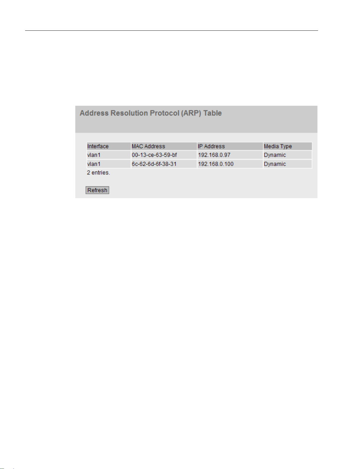
Configuring with Web Based Management
6.4 "Information" menu
6.4.4.2 IPv6 Neighbor Table
Assignment of MAC address and IPv6 address
Via the IPv6 neighbor table, there is a unique assignment of MAC address to IPv6 address. This
assignment is kept by each network node in its own separate neighbor table.
Description of the displayed values
The table has the following columns:
● Interface
Displays the interface via which the row entry was learnt.
● MAC Address
Shows the MAC address of the destination or source device.
● IP Address
Shows the IPv6 address of the destination device.
● Media Type
Shows the type of connection.
– Dynamic
The device recognized the address data automatically.
– Static
The addresses were entered as static addresses.
SCALANCE W1780/W1740 according to IEEE 802.11ac Web Based Management
94 Configuration Manual, 11/2019, C79000-G8976-C485-03
Page 95

6.4.5 Log Tables
6.4.5.1 Event log
Logging events
The device allows you to log occurring events, some of which you can specify on the page of
the System > Events menu. This, for example, allows you to record when an authentication
attempt failed or when the connection status of a port has changed.
The content of the events log table is retained even when the device is turned off.
You cannot configure anything on this page.
Configuring with Web Based Management
6.4 "Information" menu
SCALANCE W1780/W1740 according to IEEE 802.11ac Web Based Management
Configuration Manual, 11/2019, C79000-G8976-C485-03 95
Page 96

Configuring with Web Based Management
6.4 "Information" menu
Description
● Severity Filters
You can filter the entries in the table according to severity. To display all the entries, enable
or disable all parameters.
Note
A maximum of 2000 entries in the table are possible for each severity. If the maximum
number of entries is reached for a severity, the oldest entries of this severity are overwritten
in the table. The table remains permanently in the memory.
– Info
Information
When this parameter is enabled, all entries of the category "Info" are displayed.
– Warning
Warnings
When this parameter is enabled, all entries of the category "Warning" are displayed.
– Critical
Critical
When this parameter is enabled, all entries of the category "Critical" are displayed.
The table has the following columns:
● Restart
Counts the number of restarts since you last reset to factory settings and shows the device
restart after which the corresponding event occurred.
● System Up Time
Shows the time the device has been running since the last restart when the described event
occurred.
● System Time
Shows the date and time when the described event occurred.
● Severity
Shows the severity of the message.
● Log Message
Displays a brief description of the event that has occurred. You will find the list of possible
messages in Appendix D (Page 349) of the configuration manual.
If the system time is set, the time is also displayed at which the event occurred.
SCALANCE W1780/W1740 according to IEEE 802.11ac Web Based Management
96 Configuration Manual, 11/2019, C79000-G8976-C485-03
Page 97

6.4.5.2 WLAN authentication log
Logging authentication attempts
This page shows a table with information on successful or failed authentication attempts.
Configuring with Web Based Management
6.4 "Information" menu
Description
You cannot configure anything on this page.
● Severity Filters
You can filter the entries in the table according to severity. To display all the entries, enable
or disable all parameters.
Note
A maximum of 2000 entries in the table are possible for each severity. If the maximum
number of entries is reached for a severity, the oldest entries of this severity are overwritten
in the table. The table remains permanently in the memory.
– Info
Information
When this parameter is enabled, all entries of the category "Info" are displayed.
– Warning
Warnings
When this parameter is enabled, all entries of the category "Warning" are displayed.
– Critical
Critical
When this parameter is enabled, all entries of the category "Critical" are displayed.
SCALANCE W1780/W1740 according to IEEE 802.11ac Web Based Management
Configuration Manual, 11/2019, C79000-G8976-C485-03 97
Page 98

Configuring with Web Based Management
6.4 "Information" menu
The table has the following columns:
● Restart
Counts the number of restarts since you last reset to factory settings and shows the device
restart after which the corresponding event occurred.
● System Up Time
Shows the time the device has been running since the last restart when the described event
occurred.
● System Time
Shows the date and time when the described event occurred.
● Severity
Shows the severity of the message.
● Log Message
Displays a brief description of the event that has occurred. You will find the list of possible
messages in Appendix D (Page 349) of the configuration manual.
If the system time is set, the time is also displayed at which the event occurred.
6.4.6 Faults
Error status
If a fault occurs, it is shown on this page. On the device, faults are indicated by the red fault LED
lighting up.
Internal faults of the device and faults that you configure on the following pages are indicated:
● "System > Events"
● "System > Fault Monitoring"
The calculation of the time of a fault always begins after the last system start. If there are no
faults present, the fault LED switches off.
SCALANCE W1780/W1740 according to IEEE 802.11ac Web Based Management
98 Configuration Manual, 11/2019, C79000-G8976-C485-03
Page 99

Description
Configuring with Web Based Management
6.4 "Information" menu
The page contains the following boxes:
● No. of Signaled Faults
Indicates how often the fault LED lit up and not how many faults occurred.
● "Reset Counters" button
The number is reset with this button. The counter is reset when there is a restart.
The table contains the following columns:
● Fault Time
Shows the time the device has been running since the last restart when the described fault
occurred.
● Fault Description
Displays a brief description of the error/fault that has occurred.
● Clear Fault State
Some faults can be acknowledged and thus removed from the fault list, e.g. a fault of the
event "Cold/Warm Start". You can acknowledge these faults or remove them from the fault
list with the "Clear Fault State" button.
6.4.7 Redundancy
Introduction
The page shows the current information about the Spanning Tree and the settings of the root
bridge.
If Spanning Tree is turned off, only the basic information about this device is displayed.
SCALANCE W1780/W1740 according to IEEE 802.11ac Web Based Management
Configuration Manual, 11/2019, C79000-G8976-C485-03 99
Page 100

Configuring with Web Based Management
6.4 "Information" menu
If Spanning Tree is turned on, the information about the status of the instance selected in the
"Instance ID" drop-down list is displayed and the information about the configured ports is
shown in the table. The information shown depends on the Spanning Tree mode.
Description
The page contains the following boxes:
● Spanning Tree Mode
Shows the set mode. You specify the mode in "Layer 2 > Configuration" and in "Layer 2 >
MSTP > General".
The following values are possible:
– '-'
– STP
– RSTP
– MSTP
● Instance ID
Shows the number of the instance. The parameter depends on the configured mode.
● Bridge Priority / Root Priority
Which device becomes the root bridge is decided based on the bridge priority. The bridge
with the highest priority (in other words, with the lowest value for this parameter) becomes
the root bridge. If several devices in a network have the same priority, the device whose
MAC address has the lowest numeric value will become the root bridge. Both parameters,
bridge priority and MAC address together form the bridge identifier. Since the root bridge
manages all path changes, it should be located as centrally as possible due to the delay of
the frames. The value for the bridge priority is a whole multiple of 4096 with a range of values
from 0 to 32768.
SCALANCE W1780/W1740 according to IEEE 802.11ac Web Based Management
100 Configuration Manual, 11/2019, C79000-G8976-C485-03
 Loading...