

Siemens RWF 50.2,RWF55.5,RWF55.6,RWF55.50A9,RWF55.61A9,RWF55.51A9,RWF55.60A9 Installation, Use And Maintenance Instructions
20089337 (2) - 05/2015
Installation, use and maintenance instructions
Compact universal controllers
MODEL
Kit RWF 50.2
GB

20089337
Translation of the original instructions
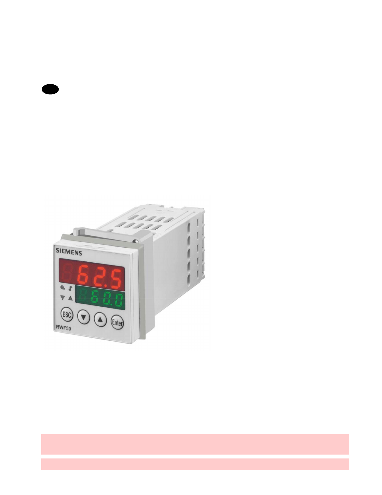
RWF50.2 and RWF50.3
Compact universal controllers
Optimized for temperature and pressure control in connection with
modulating or multistage burners and air conditioning systems
User Manual
The RWF50.2/RWF50.3 and th i s U s er M a n u a l a r e i n t e nd e d f o r use by OEMs which integrate the controllers in their
products!
Caution!
All safety, warning and technical notes contained in the Data Sheet on the
RWF50… (N7866) also apply to this document!

2/68
20089337

Supplementary documentation
Data Sheet RWF50... ............................................................................................. N7866
Environmental Declaration RWF50... ......................................................................E7866
3/68
20089337

4/68
20089337

Contents
1 Introduction...................................................................................................... 8
1.1 General notes .................................................................................................. 8
1.2 Typographical conventions.............................................................................. 9
1.2.1 Safety notes..................................................................................................... 9
1.2.2 Warning symbols ............................................................................................. 9
1.2.3 Notification symbols....................................................................................... 10
1.2.4 Presentation ..................................................................................................10
1.3 Description..................................................................................................... 11
1.4 Block structure............................................................................................... 12
2 Identification of product no. ...........................................................................13
2.1 Type field ....................................................................................................... 13
2.2 Scope of delivery ........................................................................................... 13
3 Installation .....................................................................................................14
3.1 Installation site and climatic conditions.......................................................... 14
3.2 Dimensions.................................................................................................... 14
3.3 Side-by-side mounting................................................................................... 15
3.4 Mounting the controller in a panel cutout....................................................... 15
3.5 Removing the controller from the panel cutout.............................................. 16
3.6 Cleaning the front .......................................................................................... 16
4 Electrical connections.................................................................................... 17
4.1 Installation notes............................................................................................ 17
4.2 Galvanic separation....................................................................................... 18
4.3 Assignment of terminals ................................................................................ 19
5 Operating modes ........................................................................................... 21
5.1 Low-fire operation.......................................................................................... 21
5.2 High-fire operation ......................................................................................... 22
5.2.1 Modulating burner, 3-position output ............................................................. 22
5.2.2 Modulating burner, analog output.................................................................. 23
5.2.3 2-stage burner, 3-position output................................................................... 24
5.2.4 2-stage burner, analog output .......................................................................25
5.3 Burner shutdown ...........................................................................................26
5.4 Predefined setpoint........................................................................................ 27
5.5 Response threshold (q) ................................................................................. 28
5.6 Cold start of plant ..........................................................................................29
5.7 Thermal shock protection (TSS).................................................................... 31
6 Operation....................................................................................................... 32
5/68
20089337

6.1 Meaning of display and buttons .....................................................................32
6.2 Basic display ..................................................................................................33
6.3 User level .......................................................................................................34
6.4 Manual control, modulating burner ................................................................35
6.5 Manual control, 2-stage burner ......................................................................36
6.6 Starting the self-setting function.....................................................................37
6.7 Display of software version ............................................................................38
7 Parameterization PArA....................................................................................39
8 Configuration ConF..........................................................................................41
8.1 Analog input InP1...........................................................................................42
8.2 Controller Cntr................................................................................................43
8.3 Thermal shock protection (TSS) rAFC ............................................................44
8.4 Control outputs OutP.......................................................................................45
8.5 Binary input binF............................................................................................46
8.6 Display diSP...................................................................................................47
9 Self-setting function .......................................................................................48
9.1 Self-setting function in high-fire operation......................................................48
9.2 Checking the controller parameters ...............................................................50
10 PC software ACS411 .....................................................................................51
10.1 Safety notes ...................................................................................................51
10.2 Setting the correct system parameters ..........................................................51
10.3 Changing the parameters ..............................................................................51
10.4 Place of installation ........................................................................................52
10.5 License and liability regulations .....................................................................52
10.6 Procurement of PC software ACS411 ...........................................................52
10.7 Languages .....................................................................................................52
10.8 Operating systems : Operating ......................................................................52
10.9 Prerequisites for hardware.............................................................................52
10.10 Installation......................................................................................................53
10.11 Others ............................................................................................................54
10.11.1 Use of USB port : Use of................................................................................54
10.11.2 Powering the controller via the USB port : Powering the controller via the
port.................................................................................................................54
11 What to do if ..................................................................................................55
11.1 Alarm messages: ...........................................................................................55
11.2 Others ............................................................................................................55
12 Technical data................................................................................................56
12.1 Inputs .............................................................................................................56
6/68
20089337

12.1.1 Resistance thermometers.............................................................................. 56
12.1.2 Input signals ..................................................................................................56
12.1.3 Binary input D1 .............................................................................................. 56
12.2 Monitoring the measuring circuit.................................................................... 57
12.3 Controller outputs OutP Controller o.............................................................. 57
12.4 Controller ....................................................................................................... 57
12.5 Electrical data ................................................................................................ 58
12.6 Housing .........................................................................................................58
12.7 Environmental conditions ..............................................................................59
12.8 Segment display ............................................................................................ 59
12.9 Standards and certificates ............................................................................. 59
13 Key ................................................................................................................61
14 List of figures ................................................................................................. 63
7/68
20089337
1 Introduction
1.1 General notes
Please read this User Manual before switching on the controller. Keep the
User Manual in a safe place which can be accessed by all users at all times.
Version!
This User Manual describes all necessary settings (applicable to controller
software version XXX.01.01).
Reference!
See chapter 6.7 Display of software version.
Should any problems arise during commissioning, do not make any
unauthorized manipulations on the unit. You could endanger your rights
under the warranty terms! Please contact us in such a case.
8/68
20089337
1.2 Typographical conventions
1.2.1 Safety notes
This User Manual contains information which must be observed to ensure your own
personal safety and to prevent damage to equipment and property. The instructions
and notes are highlighted by warning triangles, a hand or arrow symbol and are
presented as follows, depending on the hazard level:
Only qualified personnel are allowed to install and operate the equipment.
Qualified personnel in the context of the safety-related notes contained in this
document are persons who are authorized to commission, ground and tag devices,
systems and electrical circuits in compliance with established safety practices and
standards.
Note the following:
The controller may only be used on the applications described in the technical
documentation and only in connection with devices or components from other suppliers
that have been approved or recommended by Siemens.
The product can only function correctly and safely if shipped, stored, set up and
installed correctly, and operated and maintained as specified.
1.2.2 Warning symbols
The symbols for Caution and Attention are used in this User Manual under the
following conditions:
Caution This symbol is used where there may be a danger to
personnel if the instructions are disregarded or not
strictly observed!
Attention This symbol is used where damage to equipment or
data can occur if the instructions are disregarded or not
strictly observed!
Attention This symbol is used if precautionary measures must
be taken when handling electrostatically sensitive
components.
Qualified personnel
Correct use
9/68
20089337
1.2.3 Notification symbols
Note This symbol is used to draw your special attention to a
remark.
Reference This symbol refers to additional information in other
documents, chapters or sections.
abc¹
Footnote
Footnotes are comments, referring to specific parts of
the text. They consist of 2 parts:
1) Markings in the text are arranged as continuous
superscript numbers
2) Footnote text is placed at the bottom of the page
and starts with a number and a period
*
Action
An asterisk indicates that a required action is
described.
The individual steps are indicated by asterisks, for
example:
*
Press
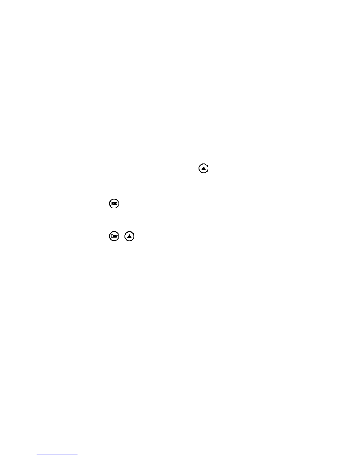
1.2.4 Presentation
Buttons
Buttons are shown in a circle. Either symbols or text are
possible. If a button has multiple assignments, the text
shown is always the text corresponding to the function
currently used.
+
Button
combinations
Two buttons shown in combination with a plus sign
means that they must be pressed simultaneously.
ConF InP
InP1
Command
chain
Arrows between words serve for finding parameters at
the configuration level more easily or for navigating in the
ACS411 setup program.
10/68
20089337

1.3 Description
The RWF50... is used primarily for the control of temperature or pressure in oil- or gasfired heating plants. Depending on the model, it is employed as a compact 3-position
controller without feedback of angular positioning or as a modulating controller with an
analog output. An external switch is provided to convert it to a 2-position controller for
controlling 2-stage burners. The built-in thermostat function switches the burner on and
off.
The controller’s operating mode can be changed from heating to cooling, or vice versa.
Reference!
See chapter 8.2 Controller Cntr.
The controllers feature two 4-digit 7-segment displays for the actual value (red) and the
setpoint (green).
The RWF50.2 has a 3-position output consisting of 2 relays to open or close a
controlling element.
The RWF50.3 has an analog output.
In modulating mode, the RWF50... operates as a PID controller. In 2-stage mode, the
RWF50... provides control based on the set switching threshold. Using the binary input,
a change to a second setpoint can be made or the setpoint can be shifted. Standard
feature is a self-setting function used to determine the PID control parameters.
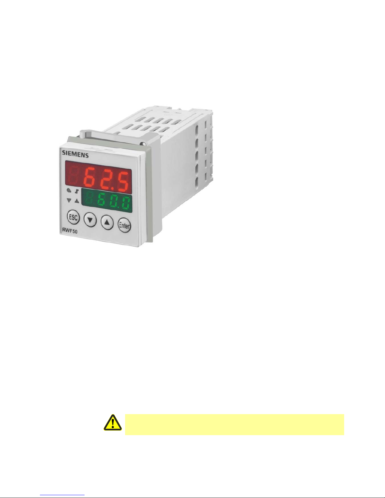
The controller insert measures 48 x 48 x 104 mm and is especially suited for installation
in control panels. All electrical connections are made via screw terminals at the rear of
the unit.
Use in heating plants
Cooling controller
RWF50...
Control
Mounting
11/68
20089337
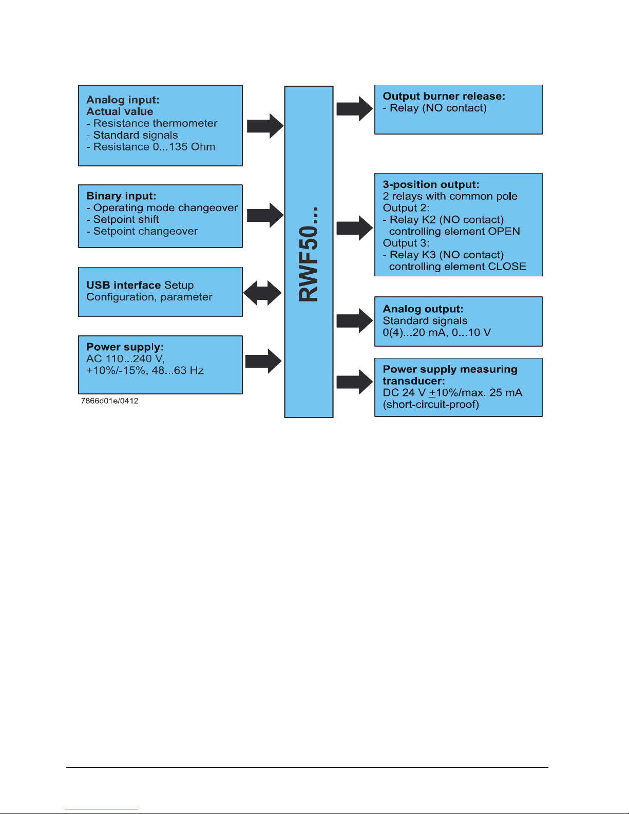
1.4 Block structure
Only RWF50.3:
Only RWF50.2:
Air damper control
Figure 1: Block structure
12/68
20089337
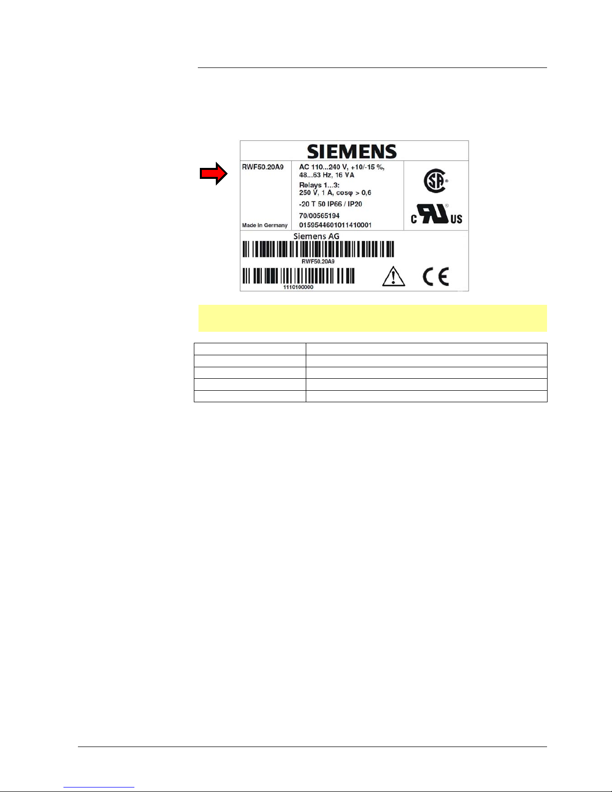
2 Identification of product no.
2.1 Type field
The type field is glued onto the housing. The arrow below indicates the product no.
7866z10/0612
Attention!
Mains supply must correspond to the operating voltage given on the type field.
Product no. Description
RWF50.20A9 Basic version with 3-position output – single pack
RWF50.21A9 Basic version with 3-position output – multipack
RWF50.30A9 Basic version with analog output – single pack
RWF50.31A9 Basic version with analog output – multipack
2.2 Scope of delivery
- Type of controller as ordered
- User Manual
Location
:
Example
Product nos.
:
13/68
20089337
3 Installation
3.1 Installation site and climatic conditions
- The installation site should be free from vibrations, dust and corrosive media
- The controller should be installed away from sources of electromagnetic fields, such
as variable speed drives or high-voltage ignition transformers
Relative humidity: 95% (noncondensing)
Ambient temperature: -20...50 °C
Storage temperature: -40...70 °C
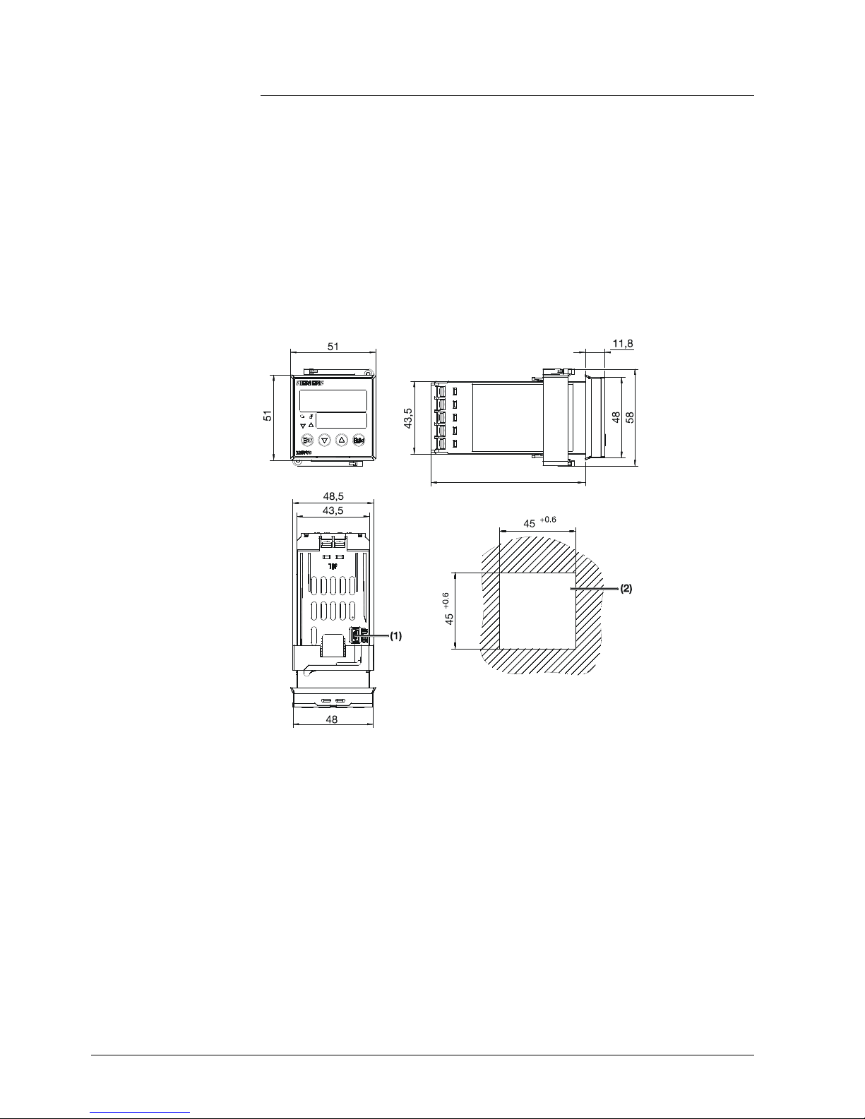
3.2 Dimensions
7866m01/0112
92
Figure 2: Dimensions of RWF50...
Key
(1) USB interface setup
(2) Panel cutout
14/68
20089337
3.3 Side-by-side mounting
If several controllers are mounted side-by-side or above one another in a control panel,
the horizontal distance between panel cutouts must be a minimum of 11 mm and the
vertical distance a minimum of 50 mm.
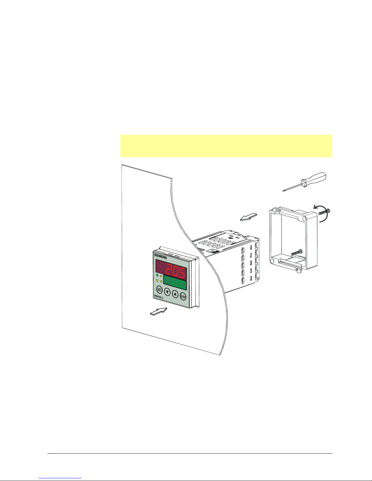
3.4 Mounting the controller in a panel cutout
*
Remove the frame
*
Fit the seal supplied with the controller
Attention!
The controller must be installed with the seal, preventing water or dirt from
entering the housing!
7866z02/0112
(1)
(2)
(3)
(3)
Figure 3: Mounting in a panel cutout
*
Insert the controller from the front into the panel cutout (1) and make certain the seal
is correctly fitted
*
Fit the frame from the rear (2) and let it engage in the grooves
*
Tighten the screws evenly with a screwdriver (3) until the controller is correctly
secured in the panel cutout
15/68
20089337

3.5 Removing the controller from the panel cutout
Attention!
When removing the controller, make certain that all cables are disconnected and that
they do not get squeezed between control panel and housing.
3.6 Cleaning the front
The front of the controller can be cleaned with normal washing/rinsing agents or
detergents.
Attention!
The front of the controller is not resistant to corrosive acids, caustic solutions and
abrasive cleaners. Do not clean with high-pressure cleaners!
16/68
20089337
4 Electrical connections
4.1 Installation notes
- The choice of cable, installation and electrical connections of the controller must
conform to VDE 0100 Regulations for the installation of power circuits with nominal
voltages below AC 1000 V, or the relevant local regulations
- The electrical connections must be made by qualified personnel
- If contact with live parts is possible while working on the unit, the controller must be
disconnected from power supply (all-polar disconnection)
Caution!
When connecting external components to the safety extra low-voltage inputs or
outputs of the RWF50... (terminals 11, 12, 13, D1, DG, G+, G-, A+, A-, and USB
port), it must be made certain that no dangerous active voltage are introduced to
the RWF50...
This can be achieved by using capsulated components with double/reinforced
insulation or SELV components, for example. If not observed, there is a risk of
electric shock.
Caution!
All screw terminals at the rear of the unit must always be properly tightened. This
applies to unused terminals as well.
Caution!
- Fusing on site must not exceed 20 A
- The fuse on the controller side (AC 250 V/1.6 A slow) conforms to IEC 60127-4
- To prevent the relay contacts from welding in the event of short-circuit in the load
circuit, fusing of the output relays must give consideration to the maximum
permissible relay current
Reference!
See chapter 12.3 Controller outputs OutP.
- No other loads may be connected to the controller’s main power supply terminals
- The electromagnetic compatibility and interference suppression levels conform to the
standards and regulations listed under Technical data
Reference!
See chapter 12.5 Electrical data.
- Input, output and supply cables should be routed separately, not parallel to one
another
- All input and output lines without connection to the power supply network must be
shielded and twisted. They must not be run close to live components or live cables.
On the controller side.
- The controller is not suited for installation in areas with explosion hazard
- Incorrect settings on the controller (setpoint, data of parameter and configuration
levels) can affect proper functioning of the process or lead to damage.
Safety devices independent of the controller, such as overpressure relief valves or
temperature limiters/monitors should therefore always be provided, and only be
capable of adjustment by qualified personnel. Please observe the relevant safety
regulations. Since self-setting cannot be expected to handle all possible control loops,
the stability of the resulting actual value should be checked
Safety regulations
Connection of
external components
Screw terminals
Fusing
Suppression of
interference
Incorrect use
17/68
20089337
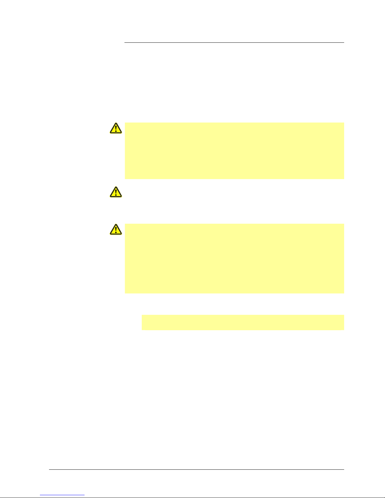
4.2 Galvanic separation
The illustration shows the maximum test voltages between the electrical circuits.
DC 50 V
AC 1500 V
AC 3300 V
Analog input
Binary input
USB interface
LED
Buttons
For resistor thermometer
or
standard signals
D1
For potential-free contacts
Setup
For PC software ACS411
InP
Power supply measuring
transducer
G+, GDC 24 V 10%/max. 25 mA
(short-circuit-proof)
+
Only RWF50.3
Analog output
A+, A-
Burner release
1P, 1N
Relay (NO contact)
Power consumption
at AC 110...240 V,
+10%/-15%, 48...63 Hz
Max. 16 VA
7866d02e/1212
Figure 4: Test voltages
18/68
20089337
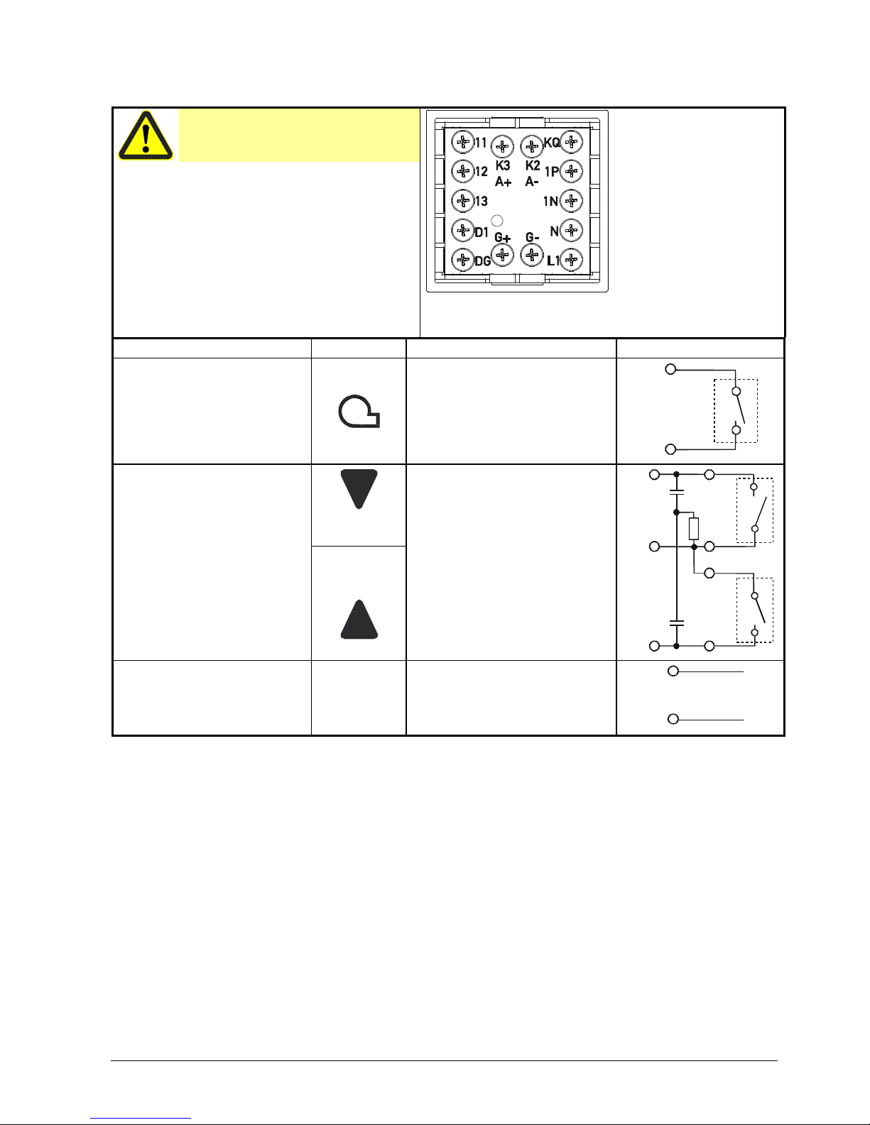
4.3 Assignment of terminals
Caution!
Electrical connections must always be
made by qualified personnel!
7866z09/0911
Figure 5: Assignment of terminals
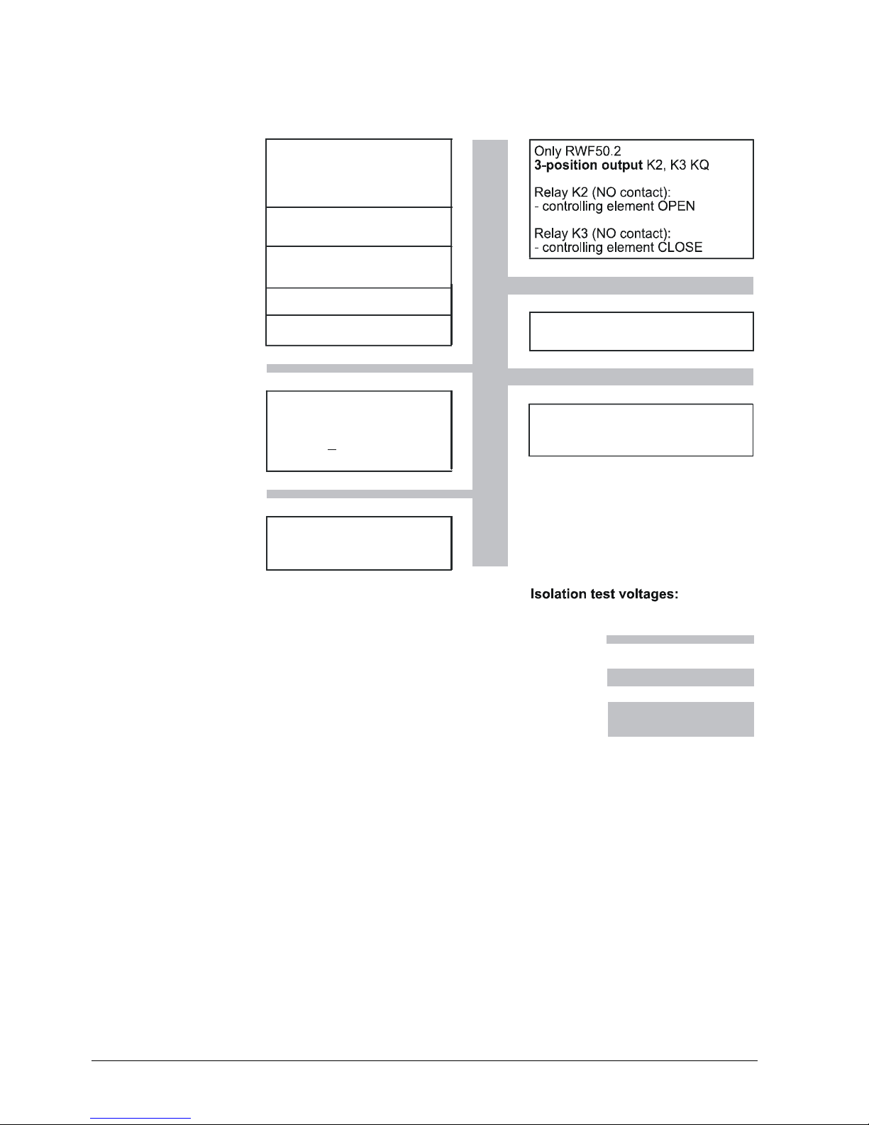
Outputs Display LED Terminal no.
Connection diagram
Relay Burner release:
Relay K1: P, 1N
1P pole
1N NO contact
1P
P
S
1N
7866a01/0911
Only RWF50.2
3-position output:
Relay K3: Controlling element
CLOSE
Relay K2: Controlling element
OPEN
K3 NO contact
KQ common pole
K2 NO contact
P
S
K3
KQ
K2
S
P
7866a02/0911
Only RWF50.3
Analog output A+, ADC 0(4)...20 mA, DC 0...10 V
A+
A-
A+
A-
+
-
7866a03/0911
19/68
20089337
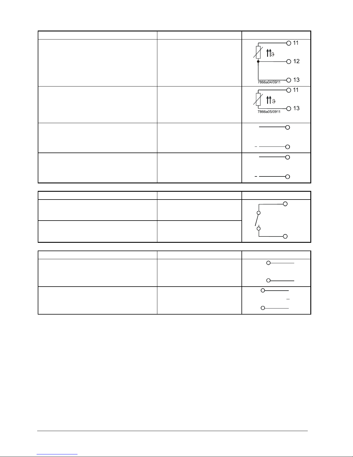
Analog input
InP1
Terminal no.
Connection diagram
Resistance thermometer in 3-wire circuit
11
12
13
Resistance thermometer in 2-wire circuit
11
13
Current input
DC 0...20 mA, 4...20 mA
12
13
13
12
+
7866a06/0911
Ix
Voltage input
DC 0...5 V, 1...5 V, 0...10 V
11
13
13
11
+
7866a06/0911
Ux
Binary inputs binF Terminal no.
Connection diagram
Binary input D1
D1
Common ground DG
DG
D1
DG
7866a08/0911
Power supply Terminal no.
Connection diagram
Power supply
AC 110...240 V +10%/-15%, 48...63 Hz
L1 Live conductor
N Neutral conductor
L1
N
7866a09/0911
Power supply measuring transducer
(short-circuit-proof)
G+
G-
G+
G-
+
-
7866a10/0412
DC 24 V 10%
max. 25 mA
+
20/68
20089337
 Loading...