

Siemens RWD Series, RWD44U, RWD45U, RWD62U, RWD68U Application Manual
...
Application Guide
Quick Reference
Document No. 125-3511
March 28, 2005
RWD Controllers
RWD44U/45U/62U/68U/82U
The RWD Controllers have standard, pre-configured applications. The respective application and setting parameters
are entered via push buttons on the controller or a software tool. See the individual Application Guides (available
online) or the Installation and Commissioning Guide for additional information. Use Tables 1 through 12 to determine
the appropriate controller model and application number.
Example: Select an application that controls two stages of electric heat and two stages of digital cooling, and
includes remote setpoint and an alarm to signal dirty air filters.
1. Select a controller based on the number of outputs and characteristics required. In this example, four digital
outputs are required. Select the RWD44U Controller (see Table 1).
Table 1. Controller Models.
Outputs
Controller Model
RWD82U 0 2
RWD62U
RWD68U 1 1
RWD44U 0 4
RWD45U 1 4
2. Determine the main control loop. Select an application number based on the output characteristics. For the
RWD44U Controller, main control loop 1X (application group 10 through 19) contains the output characteristics
that match this example (see Table 3).
3. Determine the auxiliary control loop. In this example, an auxiliary control loop (X1) is required to readjust the
setpoint remotely (see Table 4).
The controller model and application number needed for this example is RWD44U, Application #11.
Digital Output (DO)
cooling
Digital Output (DO)
heating
Analog 0 to 10 Vdc Digital
2 0
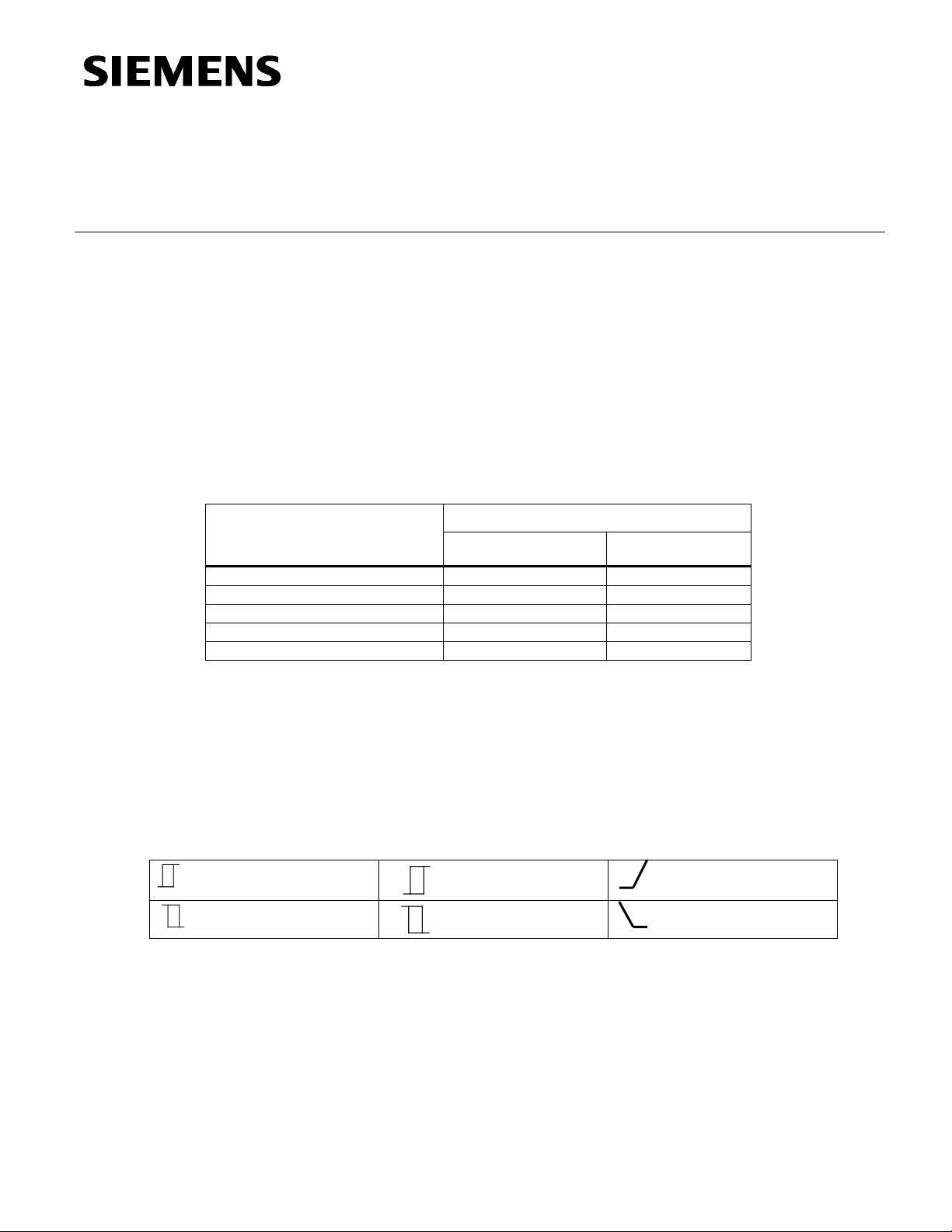
Table 2. Legend.
RV
Reversing valve cooling
RV
Reversing valve heating
Analog control loop, DA
Analog control loop, RA
Siemens Building Technologies, Inc.

Application Guide Quick Reference RWD Controllers 44U/45U/62U/68U
Document Number 125-3511
March 28, 2005
H = Heating
Table 3. RWD44U Controller Application Numbers.
Main Loop
C = Cooling
Cr = Compressor
RV = Reversing valve
RV
RV
Auxiliary Loop
#1x (2H & 2C) #2x (3-stage Cr + RV cool) # 3x (3-stage Cr + RV heat)
#x0 (Standby) #10 #20 #30
#x1 (Remote setpoint) #11 #21 #31
#x2 (Alarm) #12 #22 #32
#x3 (Filter alarm) #13 #23 #33
#x4 (Comp. shift) #14 #24 #34
#x5 (Avg. X1, X2) #15 #25 #35
#x6 (Win/Sum digital) #16 #26 #36
#x7 (Win/Sum analog) #17 #27 #37
#x8 (Sensor select) #18 #28 #38
#x9 (Active input) #19 #29 #39
Table 4. RWD44U Controller Input Configurations – X1, X2, and D1.
Applications 10 Through 39
X1
X2
#x0 (Standby) Main Standby
#x1 (Remote setpoint) Main Remote setpoint
#x2 (Alarm) Main Alarm
#x3 (Filter alarm) Main Filter alarm –
#x4(Comp. Shift) Main Compensation
#x5 (Avg. X1, X2) Main Main
#x6 (Win/Sum Digital) Main Win/Sum
#x7 (Win/Sum Analog) Main Win/Sum
#x8 (Sensor select) Main Main
#x9 (Active input) Main Standby
D1 Options
Filter Alarm Alarm Day/Night Standby
♦ ♦ ♦
♦ ♦ ♦ ♦
♦
–
♦ ♦
♦ ♦ ♦
♦ ♦ ♦ ♦
♦ ♦ ♦ ♦
♦ ♦ ♦ ♦
♦ ♦ ♦ ♦
♦ ♦ ♦ ♦
♦ ♦ ♦
–
–
Table 5. RWD44U Controller Output Configurations – Digital Outputs Q1, Q2, Q3, and Q4.
Application
Q1 Q2 Q3 Q4
Numbers
10 through 19
20 through 29
30 through 39
Heating Stage 2 (H2) Heating Stage 1 (H1) Cooling Stage 1 (C1) Cooling Stage 2 (C2)
Reversing Valve (RV) Compressor Stage 1 (Cr1) Compressor Stage 2 (Cr2) Compressor Stage 3 (Cr3)
Page 2 Siemens Building Technologies, Inc.

RWD44U/45U/62U/68U/82U Controllers Application Guide Quick Reference
Document Number 125-3511
March 28, 2005
Table 6. RWD45U Controller Application Numbers.
C = Cooling
Cr = Compressor
RV = Reversing valve
Eco = Economy
Auxiliary Loop #1x (2H2C + Eco Cool) #2x (3-stage Cr + RV cool + Eco Cool) # 3x (3-stage Cr + RV heat + Eco Cool)
#x0 (Standby) #10 #20 #30
#x1 (Remote setpoint) #11 #21 #31
#x2 (Alarm) #12 #22 #32
#x3 (Filter alarm) #13 #23 #33
#x4 (Comp. shift) #14 #24 #34
#x5 (Avg. X1, X2) #15 #25 #35
#x6 (Win/Sum Digital) N/A N/A N/A
#x7 (Win/Sum Analog) N/A N/A N/A
#x8 (Sensor select) #18 #28 #38
#x9 (Active input) #19 #29 #39
Main Loop H = Heating
RV
RV
C = Cooling
Main Loop H = Heating
Cr = Compressor
RV = Reversing valve
Eco = Economy
Auxiliary Loop #4x (2H2C + Eco Heat) #5x (3-stage Cr + RV cool + Eco Heat) #6x (3-stage Cr + RV heat + Eco Heat)
RV
RV
#x0 (Standby) #40 #50 #60
#x1 (Remote setpoint) #41 #51 #61
#x2 (Alarm) #42 #52 #62
#x3 (Filter alarm) #43 #53 #63
#x4 (Comp. shift) #44 #54 #64
#x5 (Avg. X1, X2) #45 #55 #65
#x6 (Win/Sum Digital) N/A N/A N/A
#x7 (Win/Sum Analog) N/A N/A N/A
#x8 (Sensor select) #48 #58 #68
#x9 (Active input) #49 #59 #69
Main Loop H = Heating
C = Cooling
Cr = Compressor
RV = Reversing valve
Ind = Independent
Auxiliary Loop #7x (2H2C + Ind Y) #8x (3-stage Cr + RV cool + Ind Y) #9x (3-stage Cr + RV heat + Ind Y)
RV
RV
#x0 (Standby) #70 #80 #90
#x1 (Remote setpoint) #71 #81 #91
#x2 (Alarm) #72 #82 #92
#x3 (Filter alarm) #73 #83 #93
#x4 (Comp. shift) #74 #84 #94
#x5 (Avg. X1, X2) #75 #85 #95
#x6 (Win/Sum Digital) #76 #86 #96
#x7 (Win/Sum Analog) #77 #87 #97
#x8 (Sensor select) #78 #88 #98
#x9 (Active input) #79 #89 #99
NOTE: The dotted lines indicate that the applications can be configured for either reverse or direct acting.
Siemens Building Technologies, Inc. Page 3
 Loading...