

Siemens RWD68U Technical Instructions
RWD68U
Universal Controller
Technical Instructions
Document No. 155-738
January 14, 2005
Description
Features
The Universal Controller is intended for heating, air conditioning, ventilation and
refrigeration in comfort control applications. RWD68U main loop control applications
are designed for temperature, static pressure, humidity, air pressure, fluid pressure,
refrigeration, air quality and air fluid velocity control. The controller contains preprogrammed applications.
Auxiliary control functions include:
• Day/night setpoints
• Remote setpoint control
• Limiter control
• Cascade control
• Maximum priority
• Setpoint compensation
• Summer/winter operation
Control parameters are adjusted for maximum comfort control via three buttons on the
face of the device, or with a laptop computer and Siemens Building Technologies
program software.
NOTE: For complete supporting technical documentation, including training
presentations, see www.us.sbt.siemens.com/hvp/components.
• Stand-alone electronic temperature controller with P or P+I response
• 24 Vac operating voltage
• Control application selectable via Application Number
• Active input scale can be selectable
• Limit and direction of the output scale can be freely assigned
• Two universal inputs for Siemens 1000 ohm nickel (Ni 1000), 1000 ohm platinum
(Pt 1000) temperature sensors and 0 Vdc to 10 Vdc signals
• Unit can be set as °F, °C, % or no specified unit
• One modulating 0 to 10 Vdc signal output, direct or reverse action
• One two-position output, direct or reverse action
• One digital input for day/night changeover
• Entering or changing of all data via operating buttons on the controller, is possible
without additional tools
• Computer connection for downloading pre-programmed applications via the
software tool
Product Number
RWD68U
Siemens Building Technologies, Inc.
Technical Instructions RWD68U Universal Controller
Document Number 155-738
January 14, 2005
Accessories
Warning/Caution Notations
ARG62.21 Protective enclosure for wall mounting.
SEH62.1U Program Clock
SHM62.2U 24/120 Vac Transformer
125-3481 RWD Controller Programming Tool (CD)
RWDTKU Tool Kit
Specifications
Power Supply
CAUTION:
Operating voltage 24 Vac +
Frequency 50/60 Hz
Power consumption 3.0 VA
Equipment damage may occur if you do not follow a
procedure as specified.
20%
LCD Actual and nominal values Four digits
Setpoint adjustment range -58°F to 302°F (-50°C to 150°C)
Display Resolution
(does not relate to controller
accuracy)
Siemens Ni 1000 ohm 1°F (0.5°C)
Pt 1000 ohm 1°F (0.5°C)
Active sensor Depends on setting range
Environmental Conditions Storage and transport
Temperature -13°F to 158°F (-25°C to 70°C)
Humidity <95% rh
Operation
Temperature 32°F to 122°F (0°C to 50°C)
Humidity <95% rh
Regulatory Approvals Conforms to requirements
UL UL listed to 916 Energy
Management Equipment
Terminals Screw terminals, min./max. conductors Minimum: 24 AWG (1)
Maximum: 16 AWG (2), or 14 AWG (1)
Weight RWD68U Controller 10.72 oz (304 grams)
With packaging 12.64 oz (358 grams)
Analog Inputs X1, X2
Siemens Ni 1000 ohm @ 32°F
Controller measuring range -58°F to 302°F (50°C to 150°C)
Maximum cable length for 14 AWG 984 ft (300 m)
(0°C)
Pt 1000 ohm at 32°F (0°C) Controller measuring range -4°F to 356°F (-20°C to 180°C)
Maximum cable length for 14 AWG 984 ft (300 m)
Analog voltages
(For measured variable in °F.
°C, % or without unit)
Range 0 to 10 Vdc corresponding to
adjustable range from –100 to
8000 (°F, °C, % or no unit)
Maximum cable length for 14 AWG 984 ft (300 m)
Remote setpoint X2 Range 0 to 1000 ohm corresponding to
adjustable range from –100 to
8000 (°C, °F, % or no unit)
Maximum cable length for 14 AWG 984 ft (300 m)
Digital input D1 Polling voltage for control commands (D…M) 15 Vdc
Current consumption <15 mA
Analog outputs Y1, Y2 Range 0 to 10 Vdc
Maximum current +1 mA
Digital output (Q1) Relay contacts (potential-free)
Voltage: 24 Vac
Maximum rating: 24 Vac to 240 Vac
6A RES/5 FLA/30 LRA/1/2 HP
30 Vdc, 4A
Page 2 Siemens Building Technologies, Inc.
RWD68U Universal Controller Technical Instructions
Document Number 155-738
January 14, 2005
Function Summary
• Controller
Stand-alone controller with one direct or reverse acting 0 to 10 Vdc output and
one two-position (ON/OFF) output with dependent and independent adjustment
on each sequence for direct acting or reverse acting. Adjustable parameters,
including proportional band and integral action time.
• Auxiliary selectable function
• Universal input X2 for one of the following auxiliary functions:
− P+I limiter function (Absolute and Relative)
− Remote setpoint
− Cascade control
− Setpoint compensation
− Winter/summer operation
− Maximum priority
• Digital input D1 for setpoint changeover day/night
Equipment
Combinations
The following Siemens devices can be connected to RWD68U Universal Controllers.
Other combinations with units from third-party manufacturers are possible, if the
input and output specifications match the RWD68U.
Table 1.
Description Document Number
Sensor with Siemens Ni 1000 temperature sensing element
QAA25U Room temperature sensor with setpoint adjuster
Differential Pressure Sensor 155-719
GIB Series 310 lb-in Non Spring Return Actuators
GBB Series 177 lb-in Non Spring Return Actuators
GEB Series 132 in-lb Non Spring Return Actuators 155-318P25
GCA Series 142 in-lb Spring Return Actuators 155-173P25
GMA Series 62 in-lb Spring Return Actuators 155-315P25
SKD Valve Actuator with proportional input
SKD Valve Actuator with floating input
SKB/SKC Valve Actuator with proportional input
SKB/SKC Valve Actuator with floating input
SQX Valve Actuator with proportional input
SQX Valve Actuator with floating input
SQS Actuator with proportional input
SQS Actuator with floating input
SSC Actuator with proportional input
SSC Actuator with floating input
SSB Actuator with proportional input
SSB Actuator with floating input
SFA/SFP two-position valve actuators 155-321P25
Electric Rack and Pinion two-position actuator 155-541P25
1/2 to 2-inch two-way globe valves 155-184P25
1/2 to 2-inch three-way globe valves 155-185P25
2-12 to 6-inch two-way flange valves 155-159P25
2-1/2 to 6-inch three-way flange valves 155-160P25
MT Series 1/2 to 1-1/2-inch two-way globe valves 155-196P25
MT Series 1/2 to 1-1/2-inch three-way globe valves 155-197P25
MZ Series 1/2 to 1-inch two-way globe valves 155-198P25
MZ Series 1/2 to 1-inch three-way globe valves 155-199P25
1/2 to 1-inch zone valves 155-320P25
155-330
155-176P25
155-177P25
155-174P25
155-175P25
155-180P25
155-181P25
155-163P25
155-171P25
155-182P25
155-186P25
155-190P25
155-191P25
155-313P25
155-314P25
155-192P25
155-195P25
Siemens Building Technologies, Inc. Page 3
Technical Instructions RWD68U Universal Controller
Document Number 155-738
January 14, 2005
Software Tool
An optional, user-friendly, Windows® 95 (or later) based software tool for controller
application selection and parameter adjustment is available. It provides you with a
printout of the controller settings. This tool allows controller programming prior to
installation.
Functions
Controller Type
Main Functions
The RWD68U is a stand-alone universal controller, which performs both primary and
auxiliary control functions. The respective mode is defined by entering the
corresponding configuration and setting parameters via the push buttons on the
controller or the software tool.
The RWD68U controller can be programmed as follows:
• One sequence: Q1 Reverse or direct acting
• Two sequences: Y1 and Q1 Reverse and direct acting or
Y1 and Q1 Reverse and reverse acting (independent
and dependent control loop) or
Y2 and Q1 Direct and direct acting (independent and
dependent control loop)
NOTE: Direct Acting – As air temperature increases, the control output increases.
Reverse Acting – As air temperature increases, the control output
decreases.
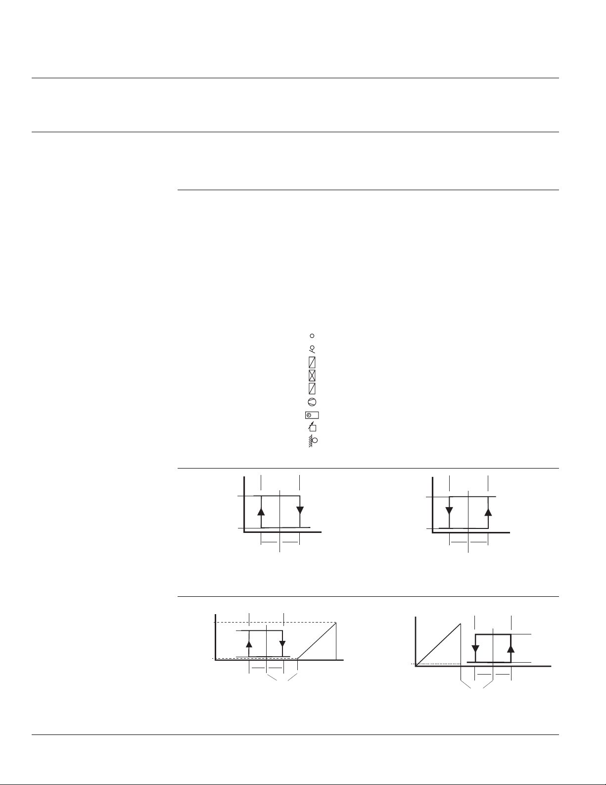
= TEMPERATURE SENSOR
= AIR DAMPER ACTUATOR
+
= HEATING COIL
-
= COOLING COIL
+
-
= HEATING OR COOLING COIL (TWO-PIPE)
= FAN OR PUMP
= TIME CLOCK
= REMOTE SET POINT UNIT
= OUTSIDE AIR SENSOR
TH0599R3
Figure 1. Frequently Used Symbols in Application Drawings.
ON
OFF
TH0746R1
Figure 2. Reverse Acting Sequence
(Application 10 to 19).
ON
OFF
TH0748R1
Q1
SD
SD SD
22
Setpoint
Heating Cooling
SD
SD SD
22
Setpoint
Temp.
Y1
XP
Temp.
Max V
Ouptut
Min V
Voltagee
ON
OFF
TH0747R1
SD
SD SD
22
Setpoint
Temp.
Figure 3. Direct Acting Sequence
(Application 80 to 89).
Heating Cooling
Y1
Max V
Min V
TH0749R1
Ouptut
Voltagee
SD1
SD1 SD1
22
Setpoint
Q1
Temp.
ON
OFF
Figure 4. Reverse and Direct Acting
Sequences
(Application 40 to 49).
Page 4 Siemens Building Technologies, Inc.
Figure 5. Direct Acting Sequences
(Application 50 to 59).
 Loading...