

Siemens RWB30 Installation Instructions Manual
IMPORTANT!
Please read this before installing your unit.
1. Complete wiring to backplate, clip programmer onto
backplate,
powerpower
powerpower
power
up up
up up
up and rotate dial through a full
24 hour rotation.
Mounting Location
To ensure convenience of use, the RWB30 should be fitted in a position
which allows easy access. It is recommended that the unit is placed at
a height of 1.4 metres from the floor.
NB The RWB30 should not be installed in locations that are directly
exposed to water splashes or steam from cooking utensils and
kettles etc.
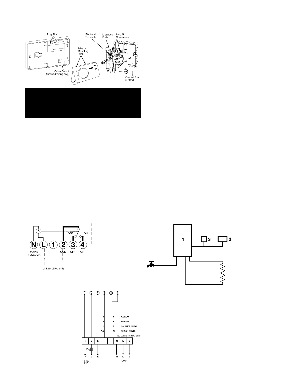
Backplate
The RWB30 is supplied with the industry standard backplate to which
the system must be wired. The backplate can be fitted directly to the
wall or it may be wired on a standard conduit box. If it is fitted to a wall,
do not mount on an unearthed metal or metallic surface. If a conduit
box is fitted all wiring to the backplate should pass through the base.
The backplate is the same as that used with: RWB3, RWB30, RWB50,
RWB100 series and RWBXT Timeswitches.
When the RWB30 is used as a direct replacement no re-wiring is
necessary, (except in the case of the RWB3 when a link should be
inserted across Terminals L and 2 as shown in Fig. 2).
Timeswitch Wiring DiagramsTimeswitch Wiring Diagrams
Timeswitch Wiring DiagramsTimeswitch Wiring Diagrams
Timeswitch Wiring Diagrams
RWB30 Timeswitch Installation Instructions
RWB30
Fig. 2
* RWB30
RWB30 Timeswitch
The voltage applied to terminal 2, is switched to terminal 4 when the
timeswitch is in the ON position and to terminal 3 when the
timeswitch is in the OFF position (see Fig. 2). If 240V direct mains
switching is required link terminals L to 2.
Note: All external wiring must comply with current IEE regulations.
Wiring of this unit should be carried out by a qualified electrician.
Whilst every effort is made to ensure the accuracy of the instructions
given, you will appreciate that the discrepancies may occur due to a
variety of reasons outside our control. If after wiring your system you
find that it does not work properly you should:
Check that you have used the correct system and wired it correctly.
Ensure that no wiring unit links have been missed and all screws are
tight.
Check with the Technical Help line, there may be a simple explanation.
(Technical Help Line: 01952 602048 Mon - Fri 9am - 5pm).
N.B. These units are not suitable for control of immersion
heaters.
Fitting the Unit to the Backplate
Tilt the bottom of the case away from the wall, locate the two slots in
the top of the case, over the two tabs at the top of the backplate. Push
the bottom of the case towards the wall, slotting the two backplate
screws into the bottom of the case, and tighten the screws. This
enables the contacts in the unit to engage with those in the backplate.
TT
TT
T
echnical Dataechnical Data
echnical Dataechnical Data
echnical Data
RR
RR
R
WB30WB30
WB30WB30
WB30
Supply: 200/240V 50HZ
Contact rating: 6A (resistance)
2A (inductive)
Switching voltage: 24 to 240V
Ambient temperature range: 0ºC to 30ºC
Environmental humidity: 90% RH
Housing: ABS resistant to fire as EN60730 standard
Safety Standard: Conforms to EN60730, class A for use in
normal pollution situation.
s
Siemens Building Technologies Ltd.
Landis & Staefa Division
Hortonwood 30, Telford TF1 4ET
Tel: (01952) 677690
Fax: (01952) 602059
Help Desk Tel: (01952) 602048
Orders Tel: (01952) 602063
Application Example
COMBI BOILER
Key
1 Combi Boiler 2 RWB30 Timeswitch 3 RAD Room Thermostat
Wiring Diagram for Combination BoilersWiring Diagram for Combination Boilers
Wiring Diagram for Combination BoilersWiring Diagram for Combination Boilers
Wiring Diagram for Combination Boilers
It is a good wiring practice that
the supply to the unit should be
via a two pole disconnection
providing at least 3mm air gap.
Please note:
only insert link as above
in Fig. 2 for boilers with 240V
AC.
Be warned:
most combination boilers use
24V so do not insert the link
for these applications.
Fig. 3
RWB30
Landis & Staefa Division
RWB30 Timeswitch
User Instructions
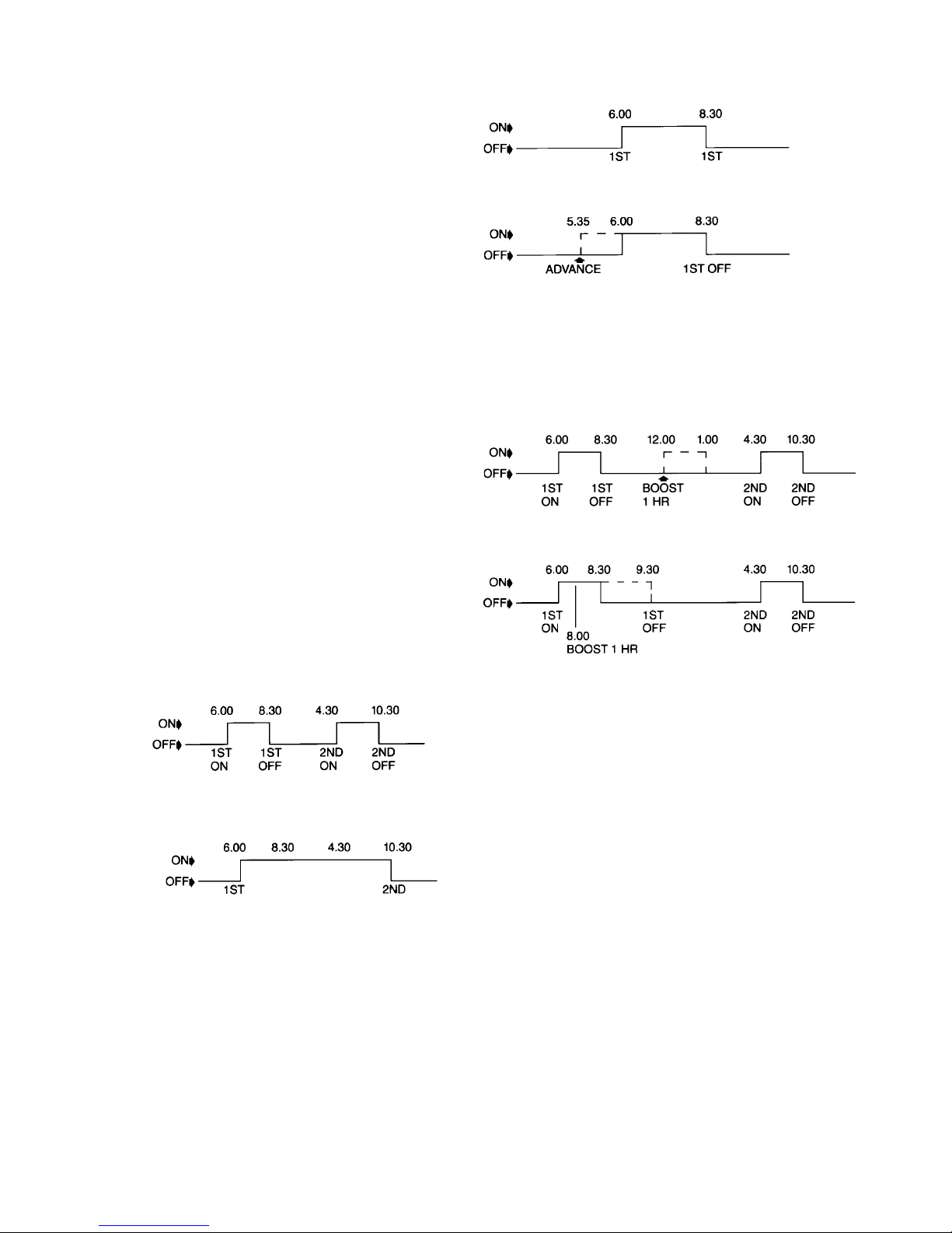
Using Override (Advance)
To advance the programme, that is to bring forward the next ON or OFF
period as shown in the example below, press the override button.
EXAMPLE: WITHOUT (OVERRIDE) ADVANCE
EXAMPLE:WITH (OVERRIDE) ADVANCE AT 5.35 AM
Adjusting the Clock (Dial Time)
To set the clock to the correct time of day rotate the dial clockwise as
shown by the arrow so that the correct time is adjacent to the raised
line with time written against it. Please note the dial is a 24 hour dial
with times shown numerically at two hour intervals and bars for hours
between.
NB Do not rotate the dial anti-clockwise as this could cause damage to
the mechanism.
Changing the ON/OFF Times
The RWB30 is supplied with factory settings (See Factory Settings)
which will operate unless you change the set times:
If you wish to change the factory settings to your own times you can do
this easily:
No 1 tappet (orange) is the first ON during the 24 hour period
No 2 tappet (blue) is the first OFF during the 24 hour period
No 3 tappet (orange) is the second ON during the 24 hour
period
No 4 tappet (blue) is the second OFF during the 24 hour period
To set the tappets to your own programme times hold the dial and slide
the relevant tappet and rotate it in either direction to your desired time,
then rotate dial through a full 24 hour rotation.
NB This should be carried out with the programmer connected and
power supply switched on to the backplate.
Power Failure
In the event of a mains power failure do not move the dial until power
has been restored. If accidentally the dial has been moved during a
power failure then rotate the dial through a full 24 hour rotation before
resetting to actual time.
TAPPET No. 1 2
COLOUR ORANGE BLUE
ON OFF
TAPPET No. 2
COLOUR BLUE
OFF
Using Boost
BOOST Pressing this button once brings the unit ON for 1 hour.
To activate BOOST push the BOOST button.
NB This feature operates in OFF, ONCE and TWICE modes
only.
EXAMPLE: BOOST PRESSED AT 12.00
EXAMPLE: BOOST PRESSED AT 8.00
TAPPET No. 1 OFF 3 4
COLOUR ORANGE ORANGE BLUE
ON ON OFF
TAPPET No. 1 2 BOOST 34
COLOUR ORANGE BLUE I HR ORANGE BLUE
ON OFF ON OFF ON OFF
ALL DAY The unit will switch ON at the morning ON and OFF at the
evening OFF.
EXAMPLE:
CONSTANT Continuously ON
When the unit is in an ON mode as above the LED lights for each
circuit will be on.
TAPPET No. 1 4
COLOUR ORANGE BLUE
Introduction
The RWB30 is an advanced daily timeswitch combining the benefits of
electronic reliability and ease of use with mechanical dial operation.
Please take time to read these operating instructions carefully.
For installation see the enclosed instructions.
Features
Up to 2 ON/OFF periods per day.
ADVANCE feature to bring forward the next ON or OFF period as
required.
BOOST feature to give an immediate 1 hour ON period at any time.
Remembers last condition (ie ON or OFF) in the event of power
failure.
Volt free contacts suitable for combination boilers.
Factory Settings
Before leaving the factory your RWB30 was programmed to switch your
system ON and OFF at the following times:
ON at 6.00 a.m. OFF at 8.30 a.m.
ON at 4.30 p.m. OFF at 10.30 p.m.
To activate this base programme:
Set clock dial to correct time. See Adjusting the Clock (Dial Time).
Operating Controls
All controls for daily use are located on and to the right hand side of the
dial.
Setting the Switching Programme
To make your selection slide the selector so that the vertical mark is
pointing to the desired position as below.
OFF Continuously OFF.
TWICE The unit will switch ON and OFF according to the morning
and evening settings.
EXAMPLE:
TAPPET No. 1 2 3 4
COLOUR ORANGE BLUE ORANGE BLUE
ON OFF ON OFF
 Loading...