

Siemens RWB29Si Installation Instruction
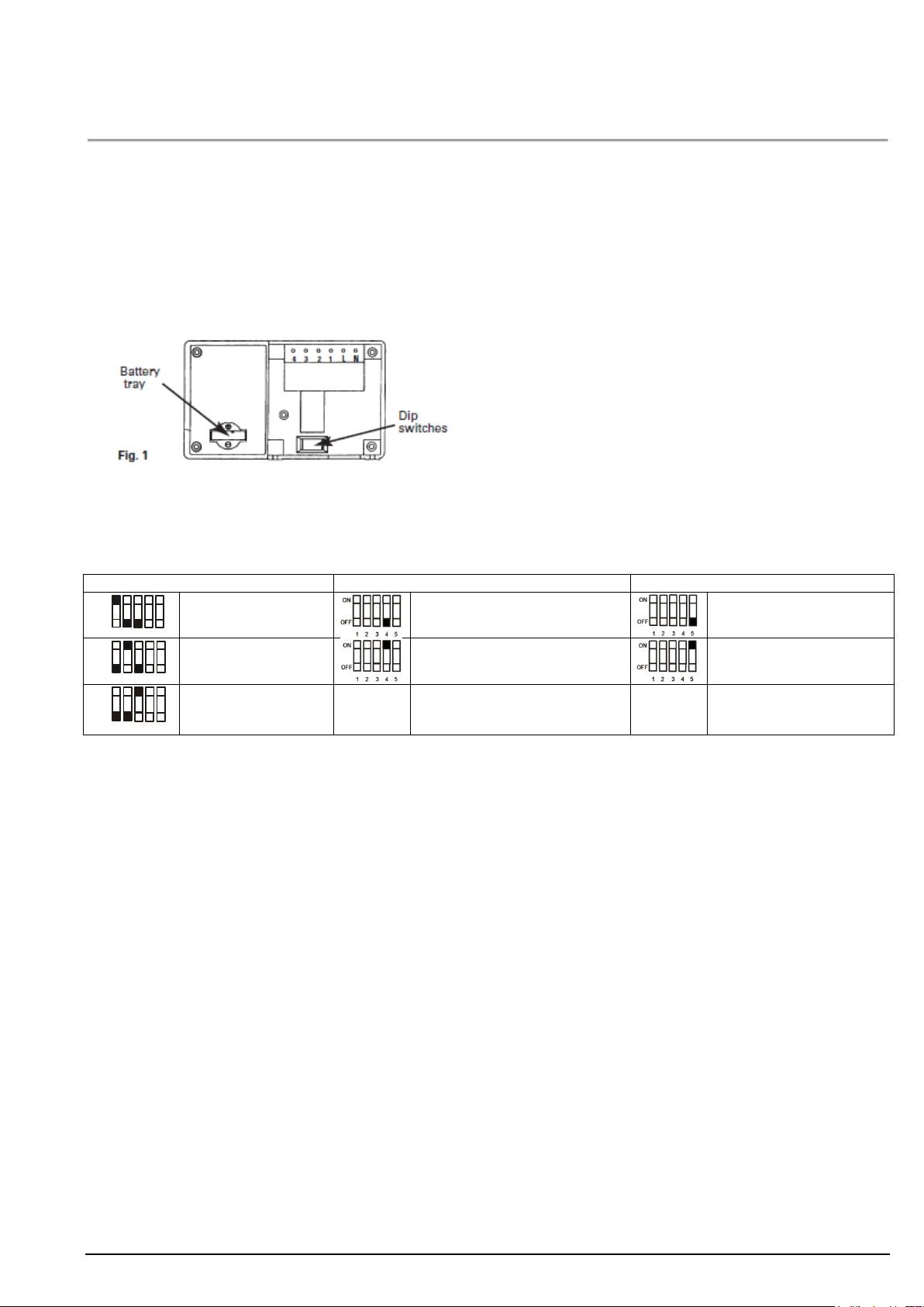
Program choice with DIP# 1, 2 & 3
ON/OFF switching periods with DIP# 4
System type with DIP# 5
1 2 3 4 5
ON
OFF
Daily
Two ON/OFF periods per day
Gravity system (10)
1 2 3 4 5
ON
OFF
Weekday/Weekend
Three ON/OFF phases per day
Fully pumped system (16)
1 2 3 4 5
ON
OFF
7 Day
RWB29Si Installation instruction
Please take a little time to fully read these installation and user instructions so as to gain the most from your RWB29Si.
1. Programme Choice
To enable you to select the programme most suitable for your needs we offer a choice of 3 programmes:
- Daily; Which means the unit will come ON and go OFF at the same times each day.
- Weekday/Weekend; Which means the unit can be altered for weekdays and weekends.
- 7 Day; Which means the unit can be set to come ON and go OFF differently on every or any day.
Please refer to the dipswitch positions on below section dipswitches
2. Dipswitches
To change the dipswitch positions first switch off the mains supply and then remove the unit from its backplate by simply loosening the two screws and pulling towards you.
When you have completed the changes to the dipswitches, replace the unit onto its backplate and then refer to the booklet supplied with the unit that relates to the programme you have selected: Daily Programming, Weekday/Weekend Programming or
7 Day Programming.
This leaflet will help you to install and commission your programmer easily and quickly.
3. Installation
1. First remove the backplate from the RWB29Si by undoing the two small screws at the base of the unit and lift out from the
bottom so that the two lugs at the top disengage from their positions.
2. The RWB29Si is factory set to provide 2 on/off switching periods per day and each day will be the same, i.e. daily
operation. To select the other styles of switching you will have to alter the dip switches which are to be found at the bottom
rear of the unit (see Fig. 1) into the relevant position for the style of operation you require. See section 2 for dip[ switch setting.
Note: Press RESET after any dip switch change.
3. Once you have completed the above you are now ready to connect the RWB29Si to the backplate, If the RWB29Si is
replacing another Landis & Gyr or Landis & Staefa product as listed below no wiring changes are required, RWB1, RWB2,
RWB20, RWB40, RWB200, RWB200cw, RWB252, RWB252cw, RWB270, RWBXP, Gloworm Mastermind, Potterton
Miniminder, Sankey Sunline.
4. If the RWB29Si is replacing another Landis & Gyr or Landis & Staefa product as listed below, these products are NOT
suitable for replacement by the RWB29Si. Return the RWB29Si to your stockist/installer and request the RWB27Si which will
fully interface with your old unit’s backplate. with the exception of the RWB3 which will require a link inserted from L to 2 on
the existing backplate RWB3, RWB7, RWB30, RWB50, RWB100, RWB152, RWB152cw, RWB170 and RWBXT.
5. Mounting Location
To ensure convenience of use, the RWB29Si should be fitted in a position which allows easy access. It is recommended that
the unit is placed at a height of 1.4 meters’ from the floor, and should not be installed where either extremes of heat or cold
exist. Care should also be taken to ensure that steam, water or oil cannot splash onto or enter either the RWB29Si or its
Siemens Building Technologies A6V10464930_enGB_ab 2017-03-09 1/2
Issued by
Siemens Switzerland Ltd.
Building Technologies Division
International Headquarters
Gubelstrasse 22
CH-6301 Zug
Tel. +41 41-724 24 24
© Siemens Switzerland Ltd, 2016
Technical specifications and availability subject to change without notice.
www.siemens.com/buildingtechnologies
backplate.
NOTE:
All external wiring must comply with current IEE regulations.
Wiring of this unit should be carried out by a competent electrician.
This unit must not be used for control of immersion heaters.
The mains supply must be isolated before replacing an existing
Programmer, failure to do so could cause damage to the RWB29Si and
will invalidate all warranty claims.
Operating voltage:
AC 230 V 50Hz
Ambient temperature range:
0 to 40°C
Power Consumption:
50mA
Environmental humidity:
80% RH
Contact rating:
Max. 6 A (resistive) / 2A (inductive)
Housing:
Fire-retardant
Switching voltage:
AC 230 V
ABS material
Program choice:
Daily
2 On/Off switching:
3 On/Off switching:
Switching periods:
2 on/off
On 06.30 Off 08.30
On 06:30 Off 08.30
Time format:
24-hour
On 16.30 Off 22.30
On 12.00 Off 14.00
Application:
Single Heating Zone and Hot Water Circuit
On 16.30 Off 22.30
System type:
Fully pumped (16)
6. Backplate
The RWB29Si is supplied with the industry standard backplate to which the system must be wired. The backplate can be fitted directly to the wall or onto a conduit box. Only conduit boxes which comply with BS1363 or BS4662 (single gang) should
be used.
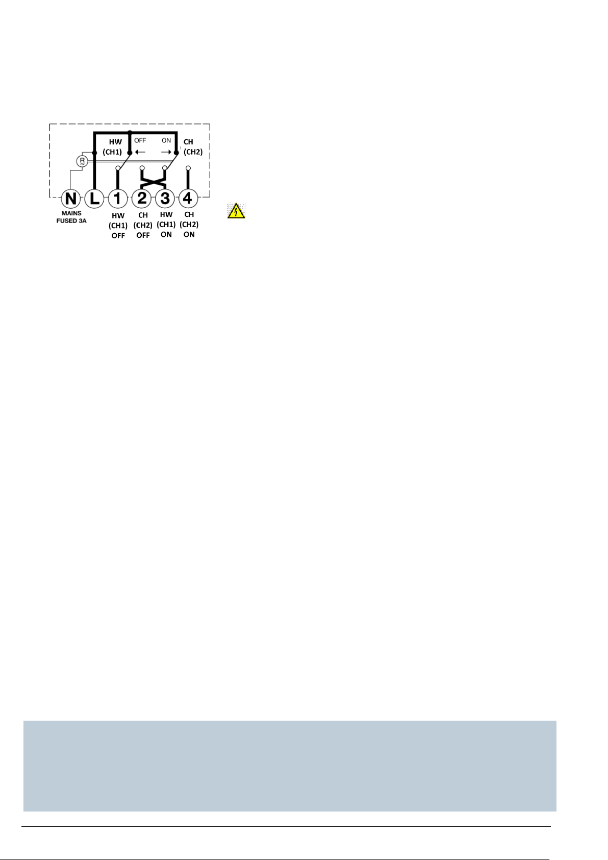
7. RWB29 Internal Wiring Diagram
8. Fitting the Unit to the Backplate
Tilt the bottom of the case away from the wall, and locate the two slots in the top of the case over the two tabs at the top of
the backplate. Push the bottom of the case towards the wall, slotting the two backplate screws into the bottom of the case,
and tighten the screws. This enables the contacts in the unit to engage with those in the backplate.
9. Commissioning (1 st time switch on)
This unit can be used to independently operate two Central Heating zones or a single Heating Zone and Hot Water Circuit.
When the unit is first powered on, the commissioning engineer is given the option to select HW & CH or CH1+CH2. The
RWB29Si is factory set to Heating Zone and Hot Water Circuit (HW & CH). If the application changes, this can be changed
by pressing the reset button on the front of the unit and resetting the desired option. For the application two Heating zone
(CH1 + CH2) apply the enclosed sticker over the button area on the front of the RWB29Si to label the buttons and indicator
lights accordingly.
RWB29Si can display the time in 24- or 12-hour format. The factory setting is 24-hour format. If there is a wish to change the
time display format then, this can be changed by pressing the reset button on the front of the unit and resetting the desired
option.
10. Technical Data
11. Preset Factory Settings
12. Troubleshot
Whilst every effort is made to ensure accuracy of the instructions given, you will appreciate that discrepancies may occur due
to a variety of reasons outside our control. If, after wiring your system, you find that it does not work properly you should:
- Check that you have used the correct system and wired it correctly
- Ensure no wiring links have been missed and all screws are tight.
- Check with your local Siemens Helpline - there may be a simple explanation.
2/2 2017-03-09 A6V10464930_enGB_a Siemens Building Technologies
 Loading...