

Siemens RWB27 Timeswitch Installation And Operating Instructions Manual
Installation and operating instructions for the
Siemens RWB27 Timeswitch.
Programme Choice
To enable you to select the programme most suitable for your needs we
offer a choice of 3 programmes.
Daily; Which means the unit will come ON and go OFF at the same times
each day.
Weekday/Weekend; Which means the unit can be altered for weekdays and
weekends.
7 Day; Which means the unit can be set to come ON and go OFF differently
on every or any day.
Please refer to the dipswitch positions on the following pages.
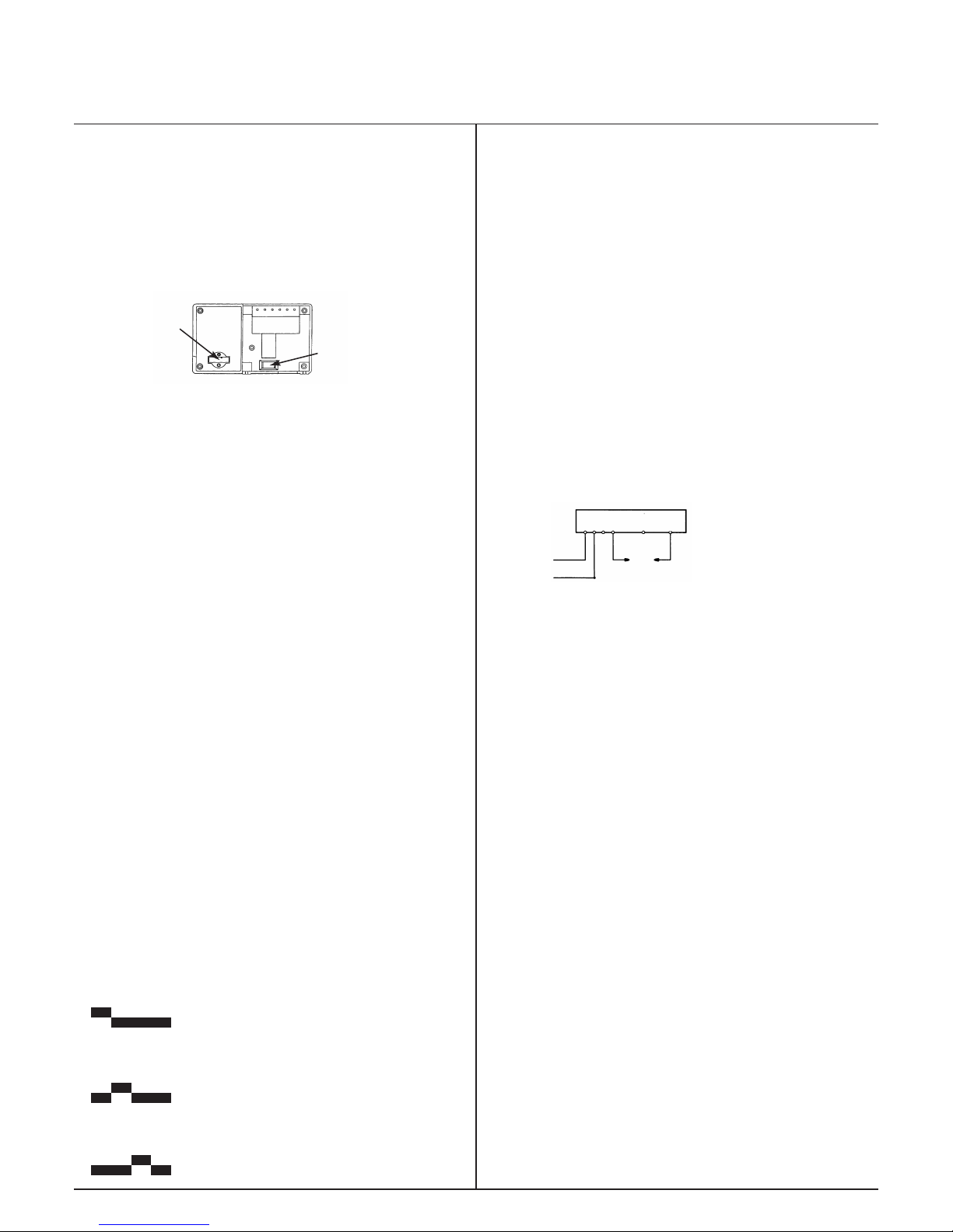
Battery
tray
Dip
switches
Fig. 1
4 3 2 1 L N
Dipswitches
To change the dipswitch positions first switch off the mains supply and then
remove the unit from its backplate by simply loosening the two screws and
pulling towards you.
To select the dipswitch position for Daily Programming dipswitch 1 should
be up and 2, 3 & 4 should be down.
To select the dipswitch position for Weekday/Weekend Programming
dipswitches 1, 3 & 4 should be down and 2 should be up.
To select the dipswitch position for 7 Day Programming dipswitches 1, 2 & 4
should be down and 3 should be up.
When you have completed the changes to the dipswitches, replace the unit
onto its backplate and then refer to the booklet supplied with the unit that
relates to the programme you have selected:-
Daily Programming.
Weekday/Weekend Programming.
7 Day Programming.
This leaflet will help you to programme your timeswitch easily and quickly.
Installation
Please take a little time to fully read these installation and user instructions
so as to gain the most from your RWB27.
1. First remove the backplate from the RWB27 by undoing the two small
screws at the base of the unit and lift out from the bottom so that the two
lugs at the top disengage from their positions.
2. Prior to installing onto the backplate, insert the battery into the battery
tray (see Fig. 1) and ensure that positive + and negative - are correctly
installed. The battery is a non-rechargeable lithium cell and in the event of
power failure will protect your programme instructions for up to 365
continuous days of power loss.
3. The RWB27 is factory set to provide 2 on/off switching periods per day and
each day will be the same, i.e. daily operation. To select the other styles of
switching you will have to alter the dip switches which are to be found at the
bottom rear of the unit (see Fig. 1) into the relevant position for the style of
operation you require.
NB Press RESET after any dip switch change.
4. Your operating styles are:-
DAILY
To select the dipswitch position for Daily Programming dipswitch 1 should
be up and 2, 3 & 4 should be down.
WEEKDAY/WEEKEND
To select the dipswitch position for Weekday/Weekend Programming
dipswitches 1, 3 & 4 should be down and 2 should be up.
7 DAY
To select the dipswitch position for 7 Day Programming dipswitches 1, 2 &
4 should be down and 3 should be up.
5. Once you have completed the above you are now ready to connect the
RWB27 to the backplate, If the RWB27 is replacing another Landis & Gyr or
Landis & Staefa product as listed below no wiring changes are required, with
the exception of the RWB3 which will require a link inserted from L to 2 on
the existing backplate RWB3, RWB7, RWB30, RWB50, RWB100, RWB152,
RWB152cw, RWB170 and RWBXT.
6. If the RWB27 is replacing another Landis & Gyr or Landis & Staefa product
as listed below, these products are NOT suitable for replacement by the
RWB27. Return the RWB27 to your stockist/installer and request the RWB29
which will fully interface with your old units backplate.
RWB1, RWB2, RWB20, RWB40, RWB200, RWB200cw, RWB252, RWB252cw,
RWB270, RWBXP, Gloworm Mastermind, Potterton Miniminder, Sankey
Sunline.
7. Mounting Location
To ensure convenience of use, the RWB27 should be fitted in a position
which allows easy access. It is recommended that the unit is placed at a
height of 1.4 metres from the floor, and should not be installed where either
extremes of heat or cold exist. Care should also be taken to ensure that
steam, water or oil cannot splash onto or enter either the RWB27 or its
backplate.
8. Backplate
The RWB27 is supplied with the industry standard backplate to which the
system must be wired. The backplate can be fitted directly to the wall or onto
a conduit box. Only conduit boxes which comply with BS1363 or BS4662
(single gang) should be used.
9. RWB27 Internal Wiring Diagram
For 240V link between L and 2
The voltage applied to terminal 2 is switched to terminal 4 when the
Timeswitch is in the ON position, and to terminal 3 when the Timeswitch is in
the OFF position. If 240V direct mains switching is required, link L to 2. (For
more information see enclosed separate wiring and interchange sheet.)
RWB27
N L 1 2 3 4
Circuit to be
controlled
A. C. Mains
NOTE:
All external wiring must comply with current IEE regulations. Wiring of this
unit should be carried out by a competent electrician. Whilst every effort is
made to ensure accuracy of the instructions given, you will appreciate that
discrepancies may occur due to a variety of reasons outside our control. If,
after wiring your system, you find that it does not work properly you should:-
• Check that you have used the correct system and wired it correctly.
• Ensure no wiring links have been missed and all screws are tight.
• Check with Siemens - there may be a simple explanation.
Technical Helpline:0870 850 0184 – Monday to Friday 9am - 5pm.
The mains supply must be isolated before replacing an existing
Timeswitch, failure to do so could cause damage to the RWB27 and will
invalidate all warranty claims.
NB: This unit must not be used for control of immersion heaters.
NOTE: If using the RWB27 to operate the pilot wire of a SIEMENS electric
panel heater link terminal L to terminal 2 and connect pilot wire to terminal
3. This unit must not be used to operate any other type of electric heating or
other potentially high current devices.
10. Fitting the Unit to the Backplate
Tilt the bottom of the case away from the wall, and locate the two slots in the
top of the case over the two tabs at the top of the backplate. Push the bottom
of the case towards the wall, slotting the two backplate screws into the
bottom of the case, and tighten the screws. This enables the contacts in the
unit to engage with those in the backplate.
Technical Data RWB27
Preset Factory Settings
2 on/off
6.30am to 8.30am and 4.30pm to 10.30pm
Supply: 200/240V 50Hz
Power Consumption: 50mA
Contact rating: 6A (resistive)
2A (inductive)
Switching voltage: 12 to 240V
Ambient temperature range: 0 to 40°C
Environmental humidity: 80% RH
Housing: Fire-retardant ABS material
Daily Programming instructions for the Siemens
RWB27 Timeswitch.
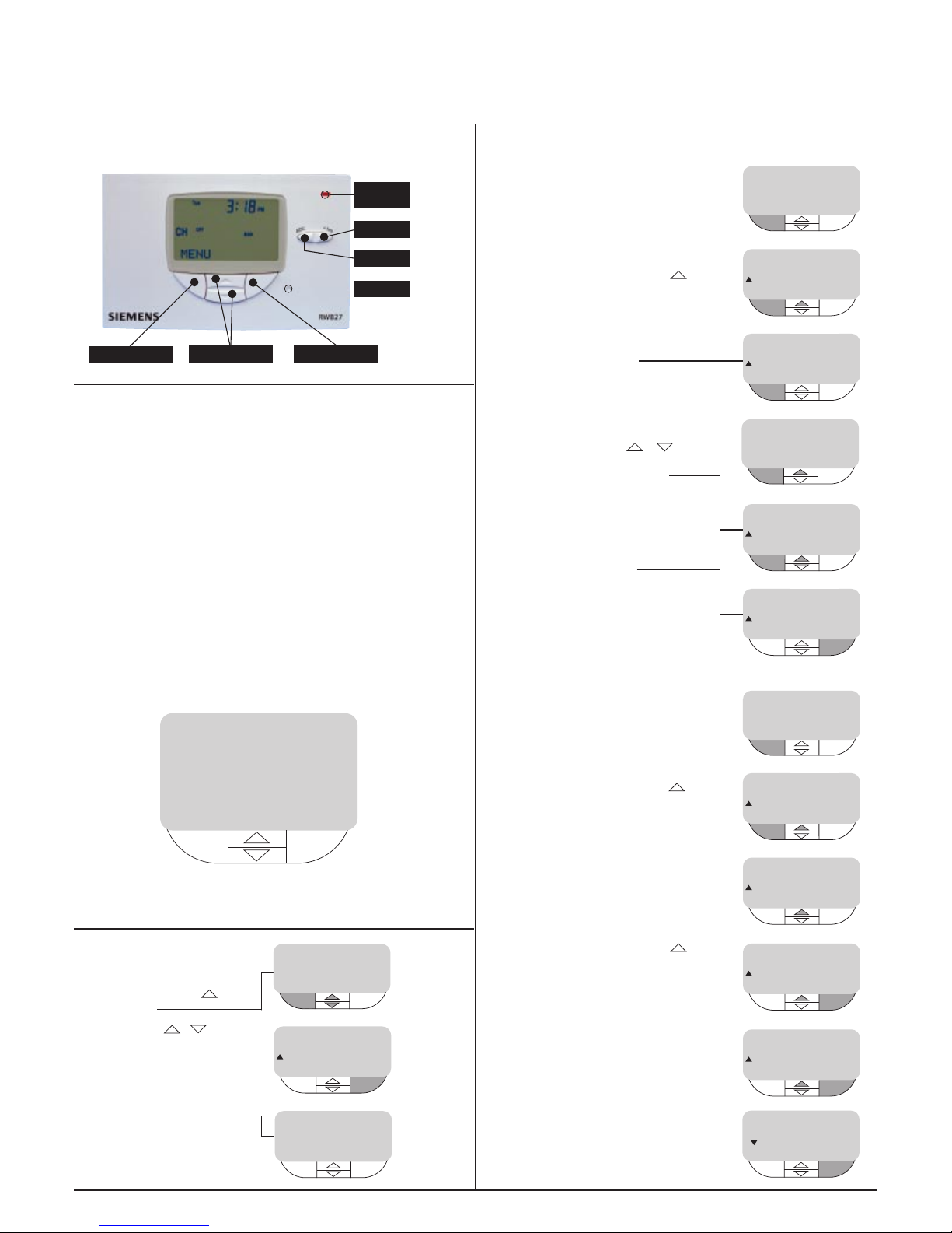
RWB27 Controls
MENU/SELECT
RESET
ON
WHEN LIT
EXTEND
ADVANCE
BACK/EXIT
UP & DOWN
Introduction
This leaflet will give you easy to follow instructions to allow you
to set your RWB27 Timeswitch to the Daily,
(same ON/OFF times each day) program.
Contents
• How do I change/set the clock?
• How do I change/set the ON/OFF times?
• How do I review the current ON/OFF times?
• What do the switching options mean?
• How do I select my Switching Options?
• How do I change summer and winter times?
• How do I set my holiday program?
• How do I activate my holiday program?
• What do the buttons do?
To commence programming first press the reset button using a
ballpoint pen or similar tool the display should show as next page.
To make it easier to follow the buttons you should be using are
coloured grey.
Display will flash as shown at first installation
RWB27 Daily
Mon Tue Wed
Thu Fri Sat Sun
12:00
PM
2P
How do I change/set
the clock?
• Press top middle button
display shows
• Alter time using +/buttons to scroll
• When correct time is shown press
left hand button ENTER
• Press right hand button EXIT
display shows
SET THE TIME
ENTER +/- BACK
12:00
PM
SET TIME
SELECT EXIT
3:37
PM
MENU
3:37
PM
CH
OFF
MAN
How do I change/set the
ON/OFF times?
• Press left hand button MENU
• Press top middle button
until SET PROGRAM is shown
• Press left hand button SELECT
display will show
MENU
3:37
PM
CH
OFF
MAN
SET PROGRAM
SELECT EXIT
CH
OFF
MAN
3:37
PM
SET 1st ON
SELECT BACK
CH
8:30
AM
3:37
PM
To change 1st ON time press
SELECT,time will flash, change
times by using +/- , when
desired time is in the display press
ENTER display will show
• Repeat as above until last OFF
time is entered
display will show
press EXIT to return to MENU
SET THE TIME
ENTER +/- BACK
12:00
PM
SET PROGRAM
SELECT EXIT
CH
10:30
AM
3:37
PM
SET 1st OFF
SELECT BACK
CH
10:30
AM
3:37
PM
How do I review the current
ON/OFF times?
• Press left hand button MENU
• Press top middle button
until REVIEW PROG is shown
• Press left hand button SELECT
• 1st ON time will be shown
REVIEW PROG
SELECT EXIT
VIEW 1st ON
BACK
MENU
3:37
PM
CH
OFF
MAN
CH
OFF
MAN
3:37
PM
CH
8:30
AM
3:37
PM
• Press top middle button
1st OFF will be shown
• Continue above two actions until
last OFF is shown
• Press right hand button BACK
then press again EXIT
(this will return you to MENU)
VIEW 1st OFF
BACK
CH
10:30
AM
3:37
PM
VIEW 2nd OFF
BACK
CH
11:30
PM
3:37
PM
REVIEW PROG
SELECT EXIT
3:37
PM
What do the switching options mean?
AUTO
This means that the RWB27 will switch ON and OFF according to
the programmed times
MANUAL OFF
This means that the RWB27 will be permanently OFF
MANUAL ON
This means that the RWB27 will be permanently ON
ONCE
This means that the RWB27 will switch ON at the first ON time and
switch OFF at the last OFF time you have programmed ignoring
any ON/OFF times in between. This is also referred to as All Day.
How do I select my four
switching options?
• Press left hand button MENU
Display shows
• Press left hand button SELECT
twice, Display shows
• Press top middle button until
your switching option is displayed
AUTO*
MANUAL OFF*
MANUAL ON*
ONCE*
*see previous section for details
• Choose desired option by pressing
ENTER
AUTO
ENTER BACK
MANUAL OFF
ENTER BACK
SET STATUS
SELECT EXIT
CH
OFF
MAN
3:37
PM
• Press right hand button BACK
• Press right hand button EXIT
Display shows
AUTO
ENTER BACK
SET STATUS
SELECT EXIT
MENU
CH
OFF AUTO
UNTIL
3:37
PM
10:30
AM
How do I change winter and
summer times?
• Press left hand button MENU
• Press top middle button
until SET TIME is shown
• Press left hand button SELECT
• Alter time using +/buttons until correct time is shown
• When correct time is shown press
left hand button ENTER, then press
right hand button EXIT to return to
MENU display
SET TIME
SELECT EXIT
MENU
3:37
PM
CH
OFF
MAN
3:37
PM
SET TIME
SELECT EXIT
4:37
PM
How do I set my holiday
program?
• Press left hand button MENU
• Press top middle button
until SET HOLIDAY is shown
• Press left hand button SELECT
display shows
number of holiday days will
flash, change amount of days
(1-99) by using +/- , when
desired amount of days is in the
display press left hand button
ENTER, then right hand button
EXIT to return to MENU
SET HOLIDAY
SELECT EXIT
ADJUST DAYS
ENTER +/- BACK
MENU
3:37
PM
CH
OFF
MAN
3:37
PM
20
CH
OFF
MAN
How do I activate my holiday
program?
• Press left hand button MENU
SET STATUS is shown,
press SELECT
• Press top middle button
until HOLIDAY is shown
• Press left hand button SELECT
display will flash as shown
your system is now in HOLIDAY
mode (OFF) and will countdown
the amount of days you have set
it for, at the end of which it will
automatically go back to your
normal set program.
You can also press CANCEL to
return to normal program mode.
HOLIDAY
SELECT BACK
HOLIDAY MODE
MENU CANCEL
3:37
PM
3:37
PM
RE 20 DAYS
MENU CANCEL
CH
OFF
MAN
3:37
PM
What do the buttons do?
ADV (ADVANCE)
This brings forward the next switching time, for example:(a) if your times were ON 7am and OFF 9am - ON 5pm and OFF
10pm and you pressed the ADV at 4pm your heating would
come ON straight away and go OFF at 10pm.
(b) if your times were ON 7am and OFF 9am - ON 5pm and OFF
10pm and you pressed the ADV at 9pm your heating would go
OFF straight away and come ON at 7am the next morning.
+ HRS
This allows you to either increase your heating time in multiples of
one hour (up to a maximum of 3 hours) during a timed ON period
or to bring on the heating in multiples of one hour (up to a
maximum of 3 hours) during an OFF period.
 Loading...