

Siemens RWB2 Installation Instructions Manual
PAGE 1
INSTALLATION AND USER INSTRUCTIONS - RWB2
s
Mounting Location
To ensure convenience of use, the RWB2 should be
fitted in a position which allows easy access. It is
recommended that the unit is placed at a height of
1.4 metres from the floor.
NB: The RWB2 should not be installed in locations
that are directly exposed to water splashes or steam
from cooking utensils and kettles etc.
Backplate
The RWB2 is supplied with the industry standard
backplate to which the system must be wired. The
backplate can be fitted directly to the wall or on to a
conduit box. If a conduit box is fitted, all wiring to the
backplate should pass through the base. Only
conduit boxes which comply with BS1363 or BS4662
(single gang should be used). The backplate is the
same as that used with: RWB20, RWB40, RWB200
series and RWBXP Programmers plus Potterton
Miniminder and Gloworm Mastermind.
When the RWB2 is used as a direct replacement no
re-wiring is necessary, (except in the case of the
RWB20 when
a neutral will be required, if one is not
present).
RWB2 Programmer
Installation Instructions
IMPORTANT!
Please read this before installing your unit.
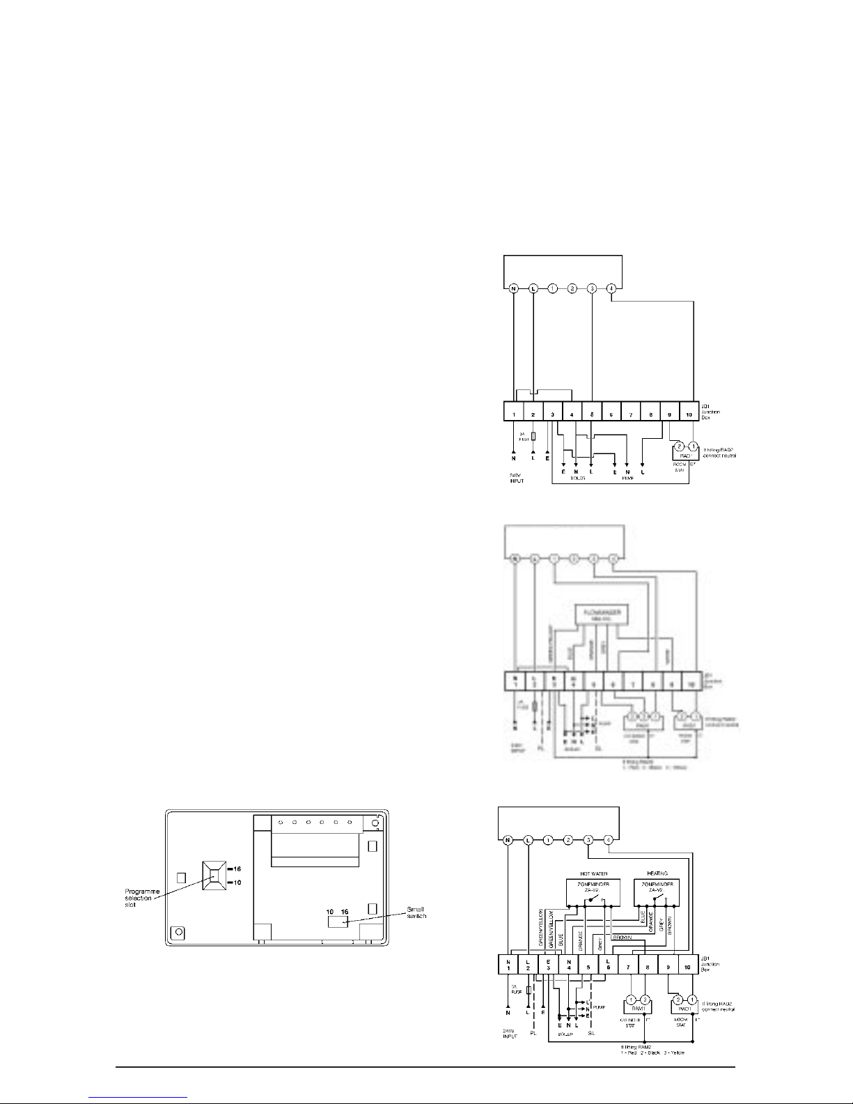
1. Select 10 or 16 way programme before clipping
unit onto backplate. (See Fig. 6).
2. Complete wiring to backplate, clip programmer
onto backplate,
power up
and rotate dial
through a full 24 hour rotation.
Fig 2.
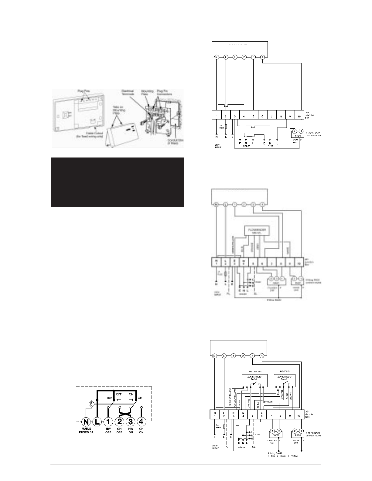
RWB2 ProgrammerWiring Diagrams
Pumped Central Heating with Gravity Hot Water
RWB2 BACKPLATE
Fig 3.
Mid-position System
RWB2 BACKPLATE
Fig 4.
Zone Valve System
RWB2 BACKPLATE
Fig 5.
PAGE 2
INSTALLATION AND USER INSTRUCTIONS - RWB2
It is good wiring practice that the supply to the unit
should be via a two pole disconnection providing at least
3mm air gap.
Line voltage applied to terminals 3 and 4 when the
programmer is in the ON position for HW and CH and to
terminals 1 and 2 when it is in the OFF position.Terminals
N, L, 1, 2, 3 and 4 connect the controls for domestic hot
water and central heating applications. (See
Figs. 3,4 and 5).
The programmers are factory set to give 10 combinations
of HW and CH, the 10 programme position is normally
used when the hot water is on a gravity system. In this
case it is not possible to have CH without HW (See
Fig. 3
for wiring diagram). If 16 programmes are required then
refer to programme selection. (
Fig. 6).
The 16 programme position is normally used on a fully
pumped system using 2 or 3 port valves, thus allowing
independent control of HW and CH. (See
Figs. 4 and 5 for
wiring diagrams).
NOTE: All external wiring must comply with current IEE
regulations. Wiring of this unit should be carried out by a
qualified electrician.Whilst every effort is made to ensure
accuracy of the instructions given, you will appreciate
that discrepancies may occur due to a variety of reasons
outside our control. If, after wiring your system, you find
that it does not work properly you should:-
• Check that you have used the correct system
and wired it correctly.
• Ensure no wiring links have been missed and
all screws are tight.
• Check with Landis & Staefa - there may be a
simple explanation.
Technical Helpline:01952 602048 – Monday to Friday 9am - 5pm.
NB: This unit must not be used for control of immersion
heaters.
Programmer range selectors
This programmer is supplied in the 10 position mode
suitable for the system as in
Fig. 3. When using systems
shown in
Figs. 4 and 5 you should carry out the following:
1. Selector sliders must be in the following position:
HW - OFF
CH - OFF
2. Insert a small, flat bladed screwdriver into the
square opening with the flat end horizontal, then
push fully up to the top of the slot opening.
3. Also move switch from 10 to 16 position, i.e. from
left to right.
Fig 6.
Technical Data RWB2
Supply: 200/240V 50Hz
Frequency: 50Hz
Contact rating: 6A (resistive)
2A (inductive)
Switching voltage: 24 to 240V
Ambient temperature range: 0 to 30°C
Environmental humidity: 90% RH
Housing: ABS resistant to fire
as EN60730 standard
Safety Standard: Conforms to EN60730,
Class A for use in normal
pollution situation.
Pumped Central Heating with Gravity Hot Water
RWB2 BACKPLATE
Fig 3.
Mid-position System
RWB2 BACKPLATE
Fig 4.
Zone Valve System
RWB2 BACKPLATE
Fig 5.
Fitting the Unit to the Backplate
Tilt the bottom of the case away from the wall, locate the
two slots in the top of the case over the two tabs at the
top of the backplate. Push the bottom of the case towards
the wall, slotting the two backplate screws into the
bottom of the case, and tighten the screws.This enables
the contacts in the unit to engage with those in the
backplate.
 Loading...