

Siemens RVS41.813, AVS37.294, AVS75.390, AVS37.290, QAA75.610 User Manual
...
Albatros
2
Heat pump controller
User manual
RVS41.813
RVS61.843
AVS75..
AVS37..
QAA75..
QAA78..
QAA55..
Edition 2.1
Controller series B
CE1U235
5en_02
28. September 2009
Siemens Switzerland Ltd
HVAC Products

2/258
Siemens Switzerland Ltd User manual RVS61.843, RVS41.813 CE1U2355en_02
HVAC Products 28. September 2009
ID A6V10084543 (doc)
ID A6V10084545 (pdf)

Contents
1 Overview........................................................................................................ 10
1.1 Product range overview.................................................................................11
1.1.1 Topology........................................................................................................11
1.1.2 Operation options .......................................................................................... 12
2 Safety notes................................................................................................... 13
2.1 Notes on product liability ...............................................................................13
3 Mounting and installation...............................................................................14
3.1 Regulations.................................................................................................... 14
3.2 Heat pump controller RVS.............................................................................14
Engineering ...................................................................................................14
Mounting method...........................................................................................14
Dimensions and drilling plan.......................................................................... 15
3.2.1 Connection terminals RVS61.843 .................................................................16
Terminal markings:RVS41.813...................................................................... 16
3.2.2 Connection terminals of RVS41.813 .............................................................19
Terminal markings RVS41.813...................................................................... 19
3.3 Extension module AVS75.390.......................................................................21
Dimensions and drilling plan.......................................................................... 21
3.3.1 Connection terminals AVS75.390.................................................................. 21
Terminal markings .........................................................................................22
Assignment of terminals ................................................................................ 22
3.4 Operator unit AVS37.294 ..............................................................................23
Mounting method...........................................................................................23
3.5 Operator unit AVS37.390 ..............................................................................24
Connections................................................................................................... 24
Dimensions....................................................................................................24
3.6 Room unit QAA55… ......................................................................................25
Engineering ...................................................................................................25
Dimensions and drilling plan.......................................................................... 25
3.7 Room unit QAA75… ......................................................................................26
Engineering ...................................................................................................26
Dimensions and drilling plan.......................................................................... 27
3.8 RF components ............................................................................................. 28
3.8.1 RF module AVS71.390..................................................................................28
3.8.2 Room unit QAA78.610................................................................................... 29
Engineering ...................................................................................................29
Mounting with the base.................................................................................. 29
Connections / power supply ..........................................................................30
Radio connection...........................................................................................30
Dimensions and drilling plan.......................................................................... 31
3.8.3 Wireless outside sensor AVS13.399 ............................................................. 32
Mounting method...........................................................................................32
Radio connection...........................................................................................33
Dimensions and drilling plan.......................................................................... 33
3/258
Siemens Switzerland Ltd User manual RVS61.843, RVS41.813 CE1U2355en_02
HVAC Products Contents 28. September 2009

3.8.4 RF repeater AVS14.390.................................................................................34
Mounting method ...........................................................................................34
Connections ...................................................................................................34
Radio connection ...........................................................................................34
Dimensions and drilling plan ..........................................................................34
3.8.5 Checking the RF components........................................................................35
4 Commissioning ..............................................................................................36
4.1 Heat pump controller......................................................................................36
5 Handling.........................................................................................................37
5.1 QAA75.. / QAA78… / AVS37.. .......................................................................37
5.1.1 Operation .......................................................................................................37
Operating elements........................................................................................37
Display choices ..............................................................................................38
Selecting pace heating mode.........................................................................38
Selecting cooling mode..................................................................................39
Selecting DHW heating mode........................................................................39
Adjusting the room temperature setpoint .......................................................40
Occupancy button ..........................................................................................40
Displaying information....................................................................................40
Manual defrost of HP / reset ..........................................................................42
5.1.2 Programming the QAA75... / QAA78… / AVS37.. .........................................43
Setting principle .............................................................................................43
Example "Setting the time of day"..................................................................43
5.1.3 User levels .....................................................................................................44
Setting structure "End user"...........................................................................45
Setting structure "Heating engineer"..............................................................45
5.1.4 Overview of the settings.................................................................................46
5.2 QAA55... ........................................................................................................77
5.2.1 Operation .......................................................................................................77
Operating elements........................................................................................77
Display choices ..............................................................................................77
Selecting pace heating mode.........................................................................77
Indication of cooling mode .............................................................................78
Adjusting the room temperature setpoint .......................................................78
Occupancy button ..........................................................................................78
5.2.2 Programming .................................................................................................79
6 The settings in detail ......................................................................................80
6.1 Time of day and date .....................................................................................80
6.2 Operator section ............................................................................................80
Operation and display ....................................................................................80
Heating circuit assignment.............................................................................82
Room sensor..................................................................................................82
Device data ....................................................................................................83
6.3 Radio links .....................................................................................................83
Binding ...........................................................................................................83
List of RF devices ..........................................................................................83
6.4 time programs ................................................................................................84
4/258
Siemens Switzerland Ltd User manual RVS61.843, RVS41.813 CE1U2355en_02
HVAC Products Contents 28. September 2009

Switching points............................................................................................. 84
Standard program.......................................................................................... 84
6.5 Holidays.........................................................................................................84
6.6 Heating circuits ..............................................................................................85
Operating mode.............................................................................................85
Setpoints........................................................................................................ 85
Heating curve ................................................................................................86
ECO functions ...............................................................................................87
Flow temperature setpoint limits....................................................................88
Room influence.............................................................................................. 89
Room temperature limitation .........................................................................90
Boost heating................................................................................................. 90
Quick setback ................................................................................................91
Optimum start / stop control ..........................................................................91
Raising the Reduced setpoint........................................................................ 92
Overtemp prot pump heating circuit ..............................................................92
Mixing valve control .......................................................................................93
Floor curing function ......................................................................................93
Excess heat draw .......................................................................................... 96
Buffer storage tank / primary controller .........................................................96
Remote control .............................................................................................. 97
Frost protection for the heating circuit ........................................................... 97
6.7 Cooling circuit 1 .............................................................................................97
Operating mode.............................................................................................98
Setpoints........................................................................................................ 98
Release .........................................................................................................98
Cooling curve................................................................................................. 99
ECO...............................................................................................................99
Summer compensation................................................................................ 100
Flow temperature setpoint limits..................................................................100
Room influence............................................................................................ 101
Room temperature limitation .......................................................................102
Mixing valve control .....................................................................................102
Dewpoint monitoring....................................................................................103
Buffer storage tank / primary controller .......................................................104
Remote control ............................................................................................ 104
Frost protection for the heating circuit ......................................................... 105
6.8 Domestic hot water......................................................................................105
Overview...................................................................................................... 105
Setpoints...................................................................................................... 105
Release .......................................................................................................106
Charging priority .......................................................................................... 107
Legionella function....................................................................................... 107
Circulating pump.......................................................................................... 109
6.9 Hx pumps ....................................................................................................109
Overview...................................................................................................... 109
Hx pumps ....................................................................................................110
6.10 Swimming pool ............................................................................................ 111
Overview...................................................................................................... 111
Setpoints...................................................................................................... 111
Priority .........................................................................................................111
Plant hydraulics ........................................................................................... 112
6.11 Primary controller / system pump ................................................................112
5/258
Siemens Switzerland Ltd User manual RVS61.843, RVS41.813 CE1U2355en_02
HVAC Products Contents 28. September 2009

Overview ......................................................................................................112
Primary controller / system pump ................................................................112
6.12 Heat pump ...................................................................................................112
Function diagrams .......................................................................................113
Condenser pump .........................................................................................114
Source pump................................................................................................115
Compressor control in plants without buffer or combi storage tank .............116
Overview of setpoint and control sensor selection.......................................117
Compressor control in plants with buffer or combi storage tank ..................118
Compressor settings ....................................................................................119
Compressor 2 ..............................................................................................122
Electric immersion heater in the flow ...........................................................124
Heat pump protection during DHW charging ...............................................126
General parameters .....................................................................................127
Heat pump protection during DHW charging ...............................................128
Defrost function for air-to-water heat pumps................................................130
Automatic defrost function ...........................................................................131
Frost protection for the heat pump...............................................................134
Cooling.........................................................................................................134
Sensor calibration. .......................................................................................137
6.13 Energy meter ...............................................................................................139
Heat volume meter.......................................................................................141
Energy counter electricity/natural gas..........................................................143
Counter/performance factor .........................................................................144
Fixed day storage (yearly performance factor) ............................................145
6.14 Cascade.......................................................................................................148
Control .........................................................................................................148
Heat source sequence .................................................................................148
Electric immersion heaters in the cascade ..................................................149
6.15 Supplementary source (only RVS41...)........................................................150
Operating mode ...........................................................................................150
Overtemperature protection .........................................................................150
Control .........................................................................................................150
6.16 Solar.............................................................................................................152
Overview ......................................................................................................152
Charging controller (dT) ...............................................................................152
Priority..........................................................................................................153
Start function................................................................................................154
Collector frost protection ..............................................................................154
Overtemperature protection for the collector ...............................................154
Medium’s evaporation temperature .............................................................155
Speed control...............................................................................................155
Yield measurement ......................................................................................155
6.17 Buffer storage tank.......................................................................................156
Overview ......................................................................................................156
Forced charging ...........................................................................................156
Automatic locks............................................................................................157
Stratification protection ................................................................................159
Overtemperature protection .........................................................................159
Recooling .....................................................................................................160
Electric immersion heater ............................................................................160
Solar integration...........................................................................................161
6.18 DHW storage tank........................................................................................161
6/258
Siemens Switzerland Ltd User manual RVS61.843, RVS41.813 CE1U2355en_02
HVAC Products Contents 28. September 2009

Abortion of DHW charging...........................................................................161
Charging control .......................................................................................... 161
Overtemperature protection......................................................................... 162
Recooling..................................................................................................... 163
electric immersion heater ............................................................................163
Excess heat draw ........................................................................................ 164
Plant hydraulics ........................................................................................... 165
Speed-controlled pump ...............................................................................165
Transfer ....................................................................................................... 167
6.19 Instantaneous DHW heater (only RVS61.843)............................................167
Overview...................................................................................................... 167
Configuration ............................................................................................... 168
Setpoints...................................................................................................... 168
Speed-controlled pump ...............................................................................168
Mixing valve control .....................................................................................168
6.20 Configuration ............................................................................................... 168
Procedure ....................................................................................................168
Preselection of plant diagram .....................................................................169
Manual setting / adjustment of partial diagrams .........................................169
Heating/cooling circuit 1 ..............................................................................169
Heating circuit 2...........................................................................................170
DHW controlling element Q3 .......................................................................171
Separate DHW circuit ..................................................................................171
Heat pump ...................................................................................................172
Solar ............................................................................................................ 173
Buffer storage tank ...................................................................................... 174
Output relay QX...........................................................................................174
Function output QX4-Mod ...........................................................................179
Sensor input BX1, BX2, BX3, BX4, BX5 .....................................................179
Input H1, H3 ................................................................................................180
Input EX1, EX2, EX3, EX4, EX5, EX6, EX7 ................................................ 186
Mixing group ................................................................................................188
Extension module ........................................................................................189
Frost protection on the extension module ...................................................189
QX extension module .................................................................................. 190
BX extension module................................................................................... 191
H2 extension module...................................................................................191
10V output UX ............................................................................................. 192
Types of sensor / readjustment ................................................................... 193
Building and room model.............................................................................193
Frost protection for the plant........................................................................ 194
Air dehumidifier............................................................................................ 194
Sensors .......................................................................................................195
Parameters ..................................................................................................195
Plant diagram ..............................................................................................195
Device data.................................................................................................. 198
6.21 LPB..............................................................................................................198
Address / power supply ............................................................................... 198
Central functions.......................................................................................... 199
Clock............................................................................................................ 201
6.22 Errors........................................................................................................... 201
Reset ........................................................................................................... 201
Error message functions.............................................................................. 202
Error history .................................................................................................202
7/258
Siemens Switzerland Ltd User manual RVS61.843, RVS41.813 CE1U2355en_02
HVAC Products Contents 28. September 2009

Error list........................................................................................................202
6.23 Service / special operation...........................................................................206
Maintenance functions .................................................................................206
Other maintenance messages .....................................................................208
Economy mode ............................................................................................208
Emergency operation...................................................................................209
Simulation ....................................................................................................209
Manual defrost .............................................................................................210
Definition of responsibilities .........................................................................210
6.24 Input / output test .........................................................................................210
Output test relays.........................................................................................210
Output test UX .............................................................................................211
Input test sensors.........................................................................................211
Input test E...................................................................................................212
6.25 State of plant................................................................................................213
Messages.....................................................................................................213
History..........................................................................................................217
6.26 Diagnostics cascade ....................................................................................217
Priority/state .................................................................................................217
6.27 Diagnostics heat source...............................................................................217
Brine-to-water heat pump ............................................................................217
Setpoints and actual values .........................................................................218
Time / start counter ......................................................................................219
Heat pump air ..............................................................................................219
Solar.............................................................................................................220
6.28 Diagnostics consumers................................................................................221
Outside temperature ....................................................................................221
Room ...........................................................................................................221
Heating circuits 1, 2, P .................................................................................222
Cooling circuit 1 ...........................................................................................222
Domestic hot water ......................................................................................223
Swimming pool.............................................................................................223
Primary controller.........................................................................................223
Common flow ...............................................................................................223
Buffer storage tank.......................................................................................223
Input H1 .......................................................................................................224
Water pressure ............................................................................................224
States multifunctional relays ........................................................................224
States of relays extension modules 1 and 2 ................................................224
6.29 Pump kick ....................................................................................................225
7 Plant diagrams .............................................................................................226
7.1 Basic diagrams ............................................................................................226
Legend (catalog of plant diagrams and extra functions) ..............................241
8 Technical data..............................................................................................242
8.1 Basic units RVS61.843 and RVS41.813......................................................242
8.2 Extension module AVS75.390 .....................................................................243
8.3 Operator and room unit AVS37... / QAA7x… / QAA55.. ..............................244
8.4 RF module AVS71.390 ................................................................................245
8.5 Wireless outside sensor AVS13.399............................................................246
8/258
Siemens Switzerland Ltd User manual RVS61.843, RVS41.813 CE1U2355en_02
HVAC Products Contents 28. September 2009

9/258
Siemens Switzerland Ltd User manual RVS61.843, RVS41.813 CE1U2355en_02
HVAC Products Contents 28. September 2009
8.6 RF repeater AVS14.390 .............................................................................. 247
8.7 Sensor characteristics ................................................................................. 248
8.7.1 NTC 1k ........................................................................................................248
8.7.2 NTC 10k ......................................................................................................249
8.7.3 Pt1000 ......................................................................................................... 249
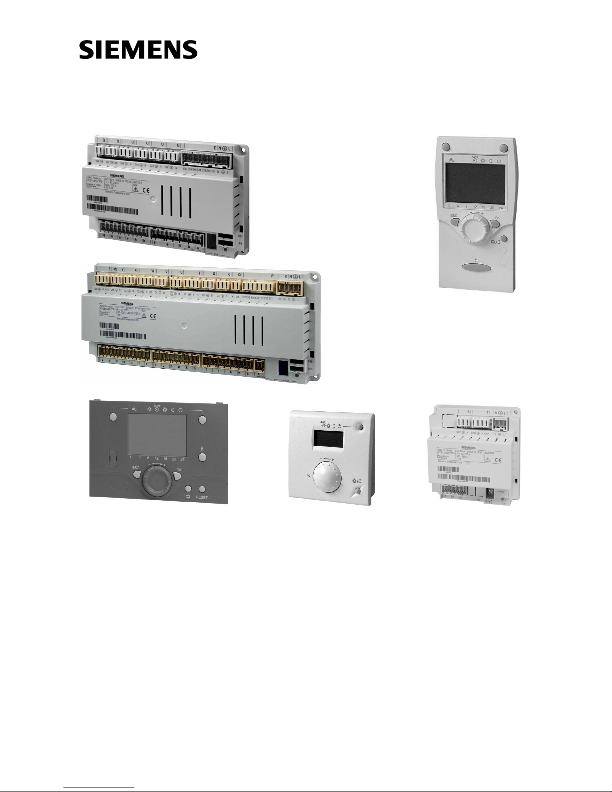
1 Overview
The present User Manual describes the products listed in the following table and covers
handling and configuration of the controls for readers ranging from endusers to heating
engineers.
Product No. (ASN) Name
RVS41.813 Basic unit heat pump
RVS61.843 Basic unit heat pump
AVS75.390 Extension module
AVS37.290 Operator unit without text display (PCB version)
AVS37.294 Operator unit with text display
QAA75.610 Room unit, for wiring
QAA75.611 Room unit, for wiring, with backlit display
QAA78.610 Room unit, wireless
QAA55.110 Room unit
RDX33.21
RDX43.2 Room thermostat with LCD to release heat pump
AVS38.291 Dummy cover (96 x 144 mm)
AVS71.390 RF module
AVS14.390 RF repeater
AVS13.399 Outside sensor with RF module
AVS82.490 Ribbon cable for extension module
AVS82.491 Ribbon cable for operator unit
The following training / demonstration cases are available:
KF8921 Demo case for RVS61.843
KF8920 Demo case for RVS41.813
The following products are described in separate pieces of documentation:
QAC34 Outside sensor
QAD36 Strap-on temperature sensor
QAZ36 Immersion temperature sensor
10/258
Siemens Switzerland Ltd User manual RVS61.843, RVS41.813 CE1U2355en_02
HVAC Products 1 Overview 28. September 2009
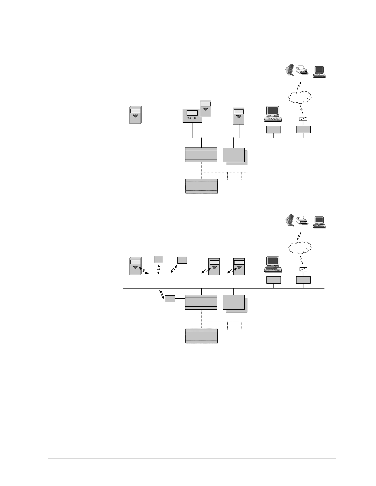
1.1 Product range overview
1.1.1 Topology
Remote
Service Tool
Mobile, SMS, Pager, Fax,
WEB,
Telephone
Network
Telephone
SMS
OCI611
OCI700
ACS700
BSB :
Boiler System Bus
Room
Unit
Service Unit
(RU)
HMI
HMI
(RU)
wired
wired
wired
Basic Unit
RVSxx
Extension
mod. AVS75…
(max. 2)
BSB-W
LPB : Local Process Bus
Basic Unit
RVS...
LPB
Wired
Remote
Service Tool
Mobile, SMS, Pager, Fax,
WEB,
Telephone
Network
Telephone
SMS
OCI611
OCI700
RF
module
ACS700
BSB :
Boiler System Bus
Room
Unit
RF
Repeater
RF
Toutside
BSB-RF
Service Unit
(RU)
HMI
(RU)
wireless
wireless
wireless
Basic Unit
RVSxx
Extension
mod. AVS75…
(max. 2)
BSB-W
LPB : Local Process Bus
Basic Unit
RVS...
LPB
Wireless
11/258
Siemens Switzerland Ltd User manual RVS61.843, RVS41.813 CE1U2355en_02
HVAC Products 1 Overview 28. September 2009
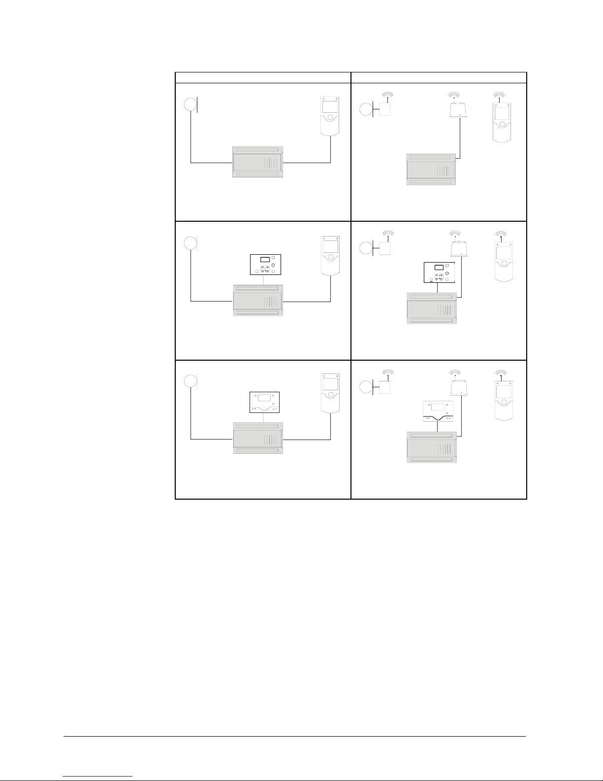
1.1.2 Operation options
Wired Wireless
C
D
A
2359Z01
T
C
D
F
A
2359Z03
T
Operation w
ith room
unit
C
E1
D
A
2359Z66
T
C
D
F
A
2359Z67
T
E1
Operation w
ith operator
unit "basic"
(optionally with additional
room unit)
C
E
D
A
2359Z02
T
C
D
F
A
E
2359Z04
T
Operation w
ith "cleartext"
operator unit
(optionally with additional room
unit)
A Basic unit RVS…
C Room unit QAA75… / 78… / QAA55..
D Outside sensor AVS13…
E Operator unit AVS37.294 (clear text)
E1 Operator unit AVS37.390 (basic)
F RF module AVS71…
12/258
Siemens Switzerland Ltd User manual RVS61.843, RVS41.813 CE1U2355en_02
HVAC Products 1 Overview 28. September 2009

2 Safety notes
2.1 Notes on product liability
• The products may only be used in building services plant and on applications as
described in this document
• When using the products, all requirements specified in the chapters on "Handling"
and "Technical data" must be satisfied
• Local regulations (for installation, etc.) must be complied with
• Do not open the units. If not observed, warranty becomes void.
13/258
Siemens Switzerland Ltd User manual RVS61.843, RVS41.813 CE1U2355en_02
HVAC Products 2 Safety notes 28. September 2009
14/258
Siemens Switzerland Ltd User manual RVS61.843, RVS41.813 CE1U2355en_02
HVAC Products 3 Mounting and installation 28. September 2009
2359Z09
3 Mounting and installation
3.1 Regulations
• Prior to installing the units, power must be turned off
• The connections for mains and low-voltage are separated
• For wiring, the requirements of safety class II must be satisfied.
• One and the same sensor cannot be connected to several inputs
Sensor and power cables must not be run in the same cable duct
3.2 Heat pump controller RVS..
Engineering
• Air circulation around the controller must be ensured, allowing the unit to emit the
heat produced by it.
A clearance of at least 10 mm must be provided for the unit's cooling slots at the top
and bottom of the housing.
That space should not be accessible and no objects should be placed there. If the
controller is enclosed in another (insulating) casing, a clearance of up to 100 mm
must be observed around the cooling slots
• The controller is designed conforming to the directives for safety class II devices
mounted in compliance with these regulations
• Power to the controller may only be supplied when completely fitted. If this is not
observed, there is a risk of electric shock hazard near the terminals and through the
cooling slots
• The controller must not be exposed to dripping water
• Permissible ambient temperature when mounted and when ready to
operate: 0…50 °C
• Power cables must be clearly separated from low-voltage cables (sensors) observing
a distance of at least 100 mm
• Heat pump
• Control panel
• Housing for wall mounting
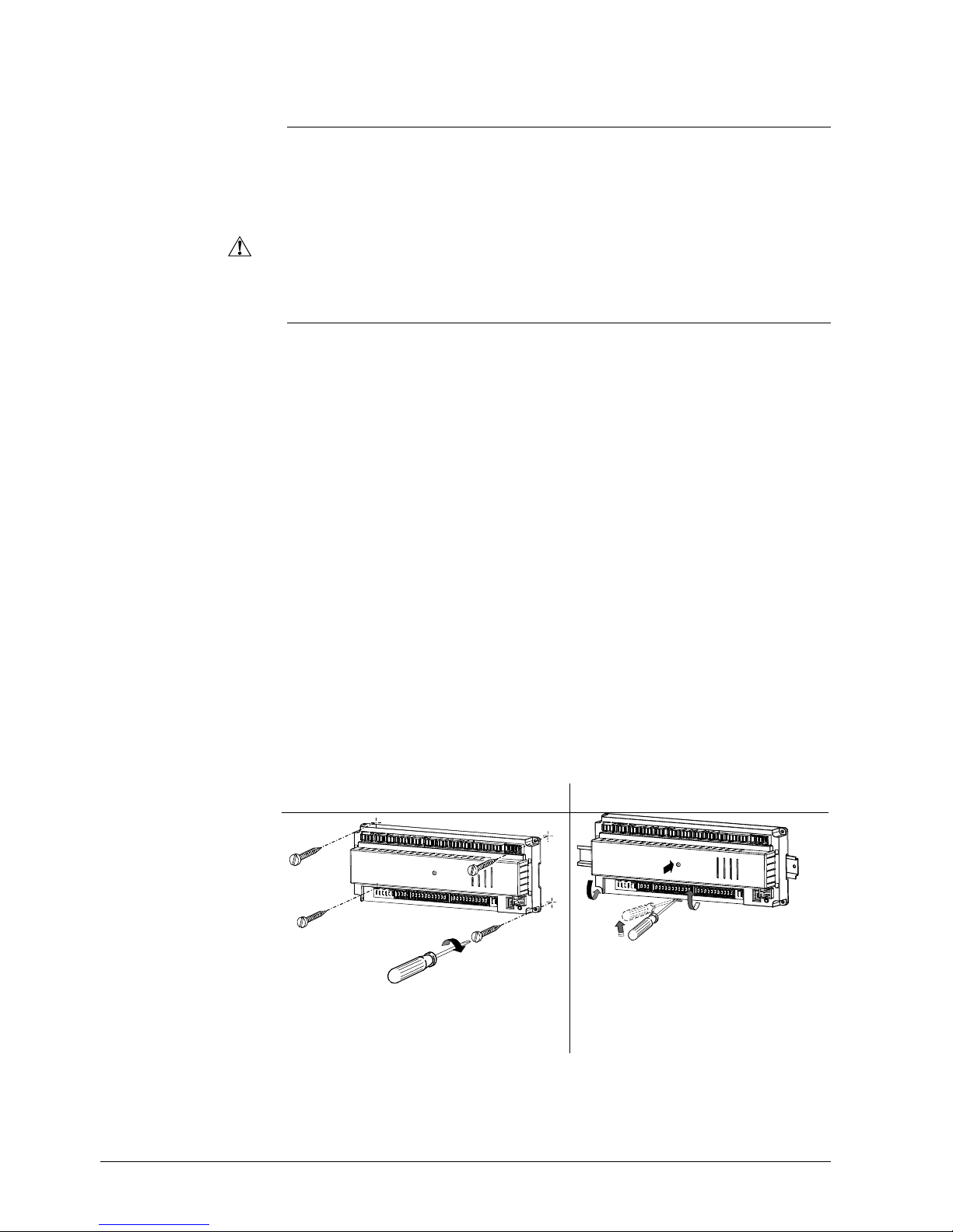
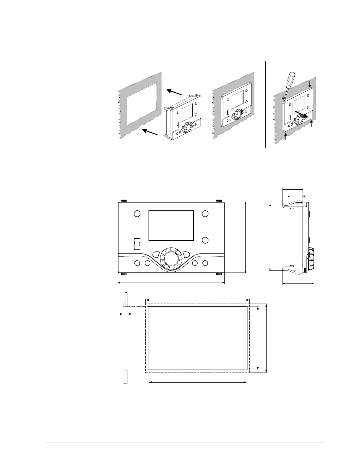
Mounting method
Scre
wed
On DIN rail
A: Mounting / B: Removal
Note:
To mount the controller on a DIN rail, a mounting
clip is required!
Electrical installation
Mounting location
A1
A2
B1
B2
2359Z11
15/258
Siemens Switzerland Ltd User manual RVS61.843, RVS41.813 CE1U2355en_02
HVAC Products 3 Mounting and installation 28. September 2009
2359Z10
x
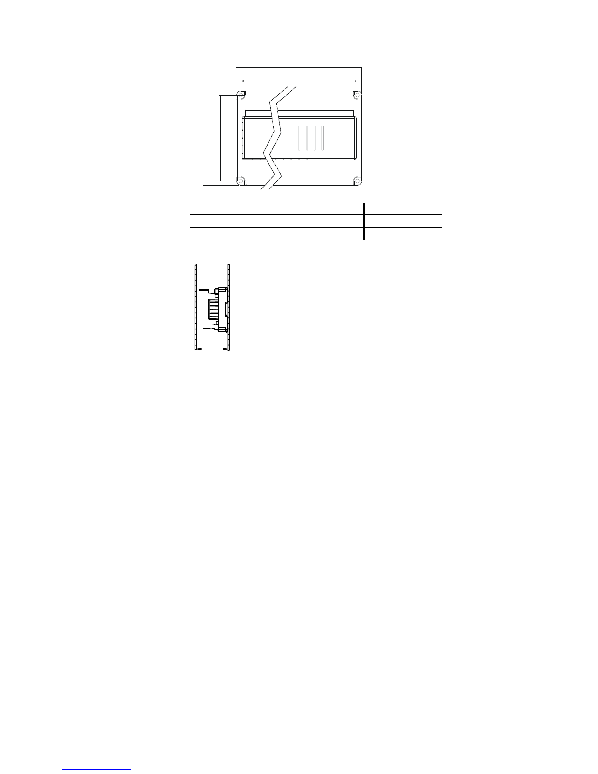
Dimensions and drilling plan
L
BL1B1
2358M01
L B H L1 B1
RVS61.843
281 121 52 270 110
RVS41.813
181 121 52 170 110
Dimension X:
Connectors with tongues, minimum 70 mm
Connector without tongues, minimum 60 mm
Total height required
Dimensions in mm
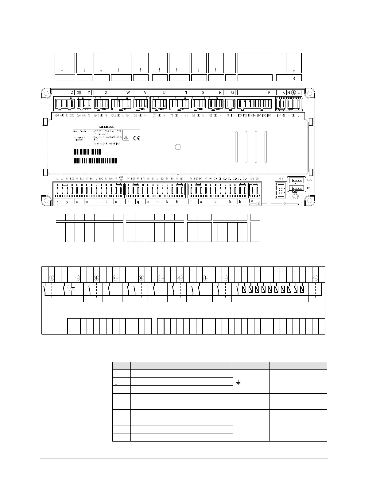
3.2.1 Connection terminals RVS61.843
QX4
N
QX3
N
QX2NQX1
Q9
N
Q8/K19
N
Y2NY1
Q2NQ3NK1
E11
EX6
EX5
EX4
EX3
EX2
EX1
E10E9N
L
N
M
B91MB71MB1MB21MB9MB3
H3MH1G+CL-
CL+
CL-
CL+
CL-
CL+
Y XW
V
UTSRQ P
rqepn
kh
b
K
L
235
5
Z09
QX6NQX5
Z
EX7
M
BX5MBX4MBX3MBX2
M
BX1MB84/B92
yxw
ut s
M
UX
z
MB
DB
a
M
B81
f
070621A
000020RVS61. 843/109
1PRVS61.843/ 109
S070621000020
Connection diagram
QX6
N
QX5
QX4
N
QX3
N
QX2
N
QX1
Q9
N
Q8
N
Y2
NY1Q2
N
Q3NK1
E11
EX7
EX6
EX5
EX4
EX3
EX2
EX1
E10E9N
L
2355Z 02
MUXM
BX 5MBX 4MBX 3MBX 2MBX 1
M
M
B91MB71MB1MB21MB9MB3MB81H3MH1G+
CL-
CL+
CL-
CL+
CL-
CL+MBDB
B84/B92
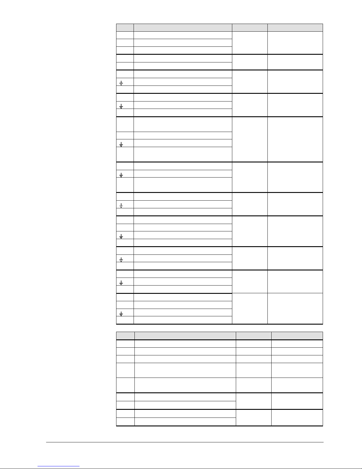
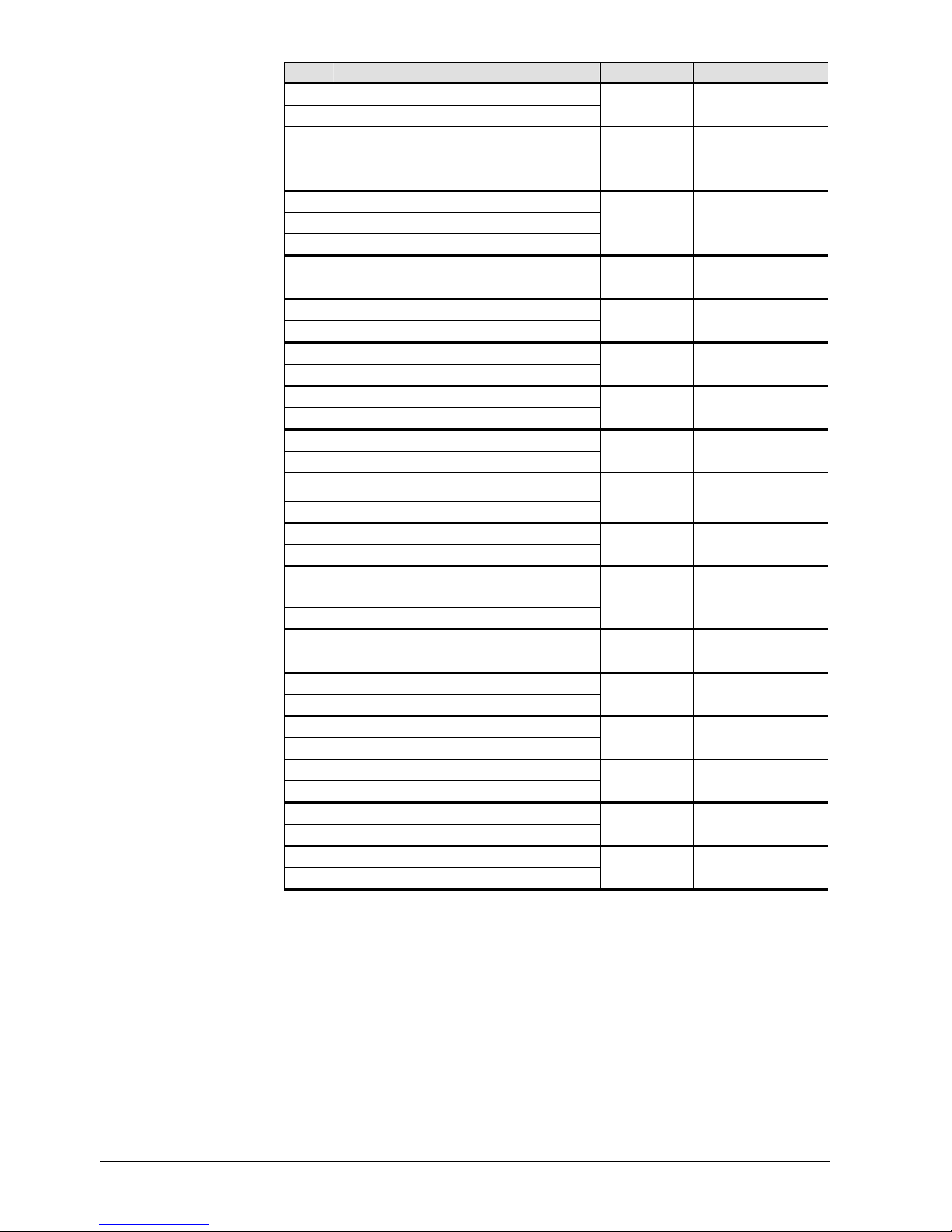
Terminal markings:RVS41.813
Use Terminal Connector type
L Mains connection, live AC 230 V
Mains connection, protective earth
N Mains connection, neutral conductor
L
N
AGP4S.03E/109
E9
Low-pressure
E10
High-pressure
K
AGP4S.02J/109
EX1 Multifunctional input EX1
EX2 Multifunctional input EX2
EX3 Multifunctional input EX3
EX4 Multifunctional input EX4
P
AGP8S.07A/109
Mains voltage
16/258
Siemens Switzerland Ltd User manual RVS61.843, RVS41.813 CE1U2355en_02
HVAC Products 3 Mounting and installation 28. September 2009
17/258
Siemens Switzerland Ltd User manual RVS61.843, RVS41.813 CE1U2355en_02
HVAC Products 3 Mounting and installation 28. September 2009
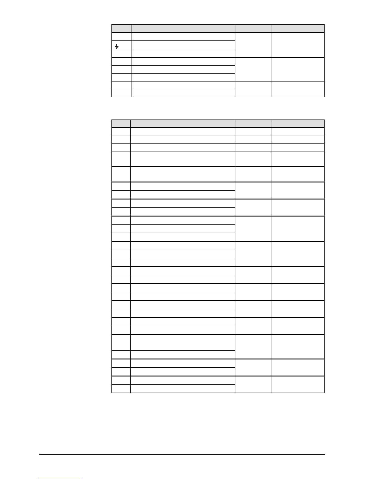
Use Terminal Connector type
EX5 Multifunctional input EX5
EX6 Multifunctional input EX6
EX7 Multifunctional input EX7
E11
Compressor 1 overload E11
K1
Compressor stage 1
Q
AGP8S.02E/109
N Neutral conductor
Protective earth
Q3 DHW charging pump / diverting valve
R
AGP8S.03A/109
N Neutral conductor
Protective earth
Q2 1. 1st heating circuit pump
S
AGP8S.03B/109
Y1 1. 1st heating circuit mixing valve
opening
N Neutral conductor
Protective earth
Y2 1. 1st heating circuit mixing valve
closing
T
AGP8S.04B/109
N Neutral conductor
Protective earth
Q8
K19
Source pump
Fan
U
AGP8S.03C/109
N Neutral conductor
Protective earth
Q9 Condenser pump
V
AGP8S.03D/109
QX1 1. Multifunctional output
N Neutral conductor
Protective earth
QX2 2. Multifunctional output
W
AGP8S.04E/109
N Neutral conductor
Protective earth
QX3 3. Multifunctional output
X
AGP8S.03E/109
N Neutral conductor
Protective earth
QX4 4. Multifunctional output
Y
AGP8S.03G/109
QX5 5. Multifunctional output
N Neutral conductor
Protective earth
QX6 6. Multifunctional output
Z
AGP8S.04C/109
Use Terminal Connector type
Service tool LPB LPB Service tool BSB BSB RF module AVS71.390 X60 Extension module AVS75.390 X50
AVS82.490/109
(cable)
Operator unit (HMI) X30
AVS82.491/109
(cable)
DB
LPB data bus
MB
LPB ground bus
a
AGP4S.02H/109
CL+ BSB data bus
CL- BSB ground bus
b
AGP4S.02A/109
Low-voltage
18/258
Siemens Switzerland Ltd User manual RVS61.843, RVS41.813 CE1U2355en_02
HVAC Products 3 Mounting and installation 28. September 2009
Use Terminal Connector type
CL+ Data bus room unit 2
CL- Ground bus room unit 2
b
AGP4S.02 A /109
CL+ Data bus room unit 1
CL- Ground bus room unit 1
G+ Power supply optional lighting
b
AGP4S.03D/109
H1 Digital / DC 0...10 V input H1
M Ground
H3 Digital / DC 0...10 V input H3
e
AGP4S.03G/109
B81 Hot-gas temperature sensor 1
M Ground
f
AGP4S.02B/109
B3 DHW temperature sensor
M Ground
h
AGP4S.02C/109
B9 Outside sensor
M Ground
k
AGP4S.02D/109
B21
Flow temperature sensor heat pump
M
Ground
n
AGP4S.02F/109
B1 Flow temperature sensor HC1
M Ground
p
AGP4S.02G/109
B71 Return temperature sensor heat pump
M Ground
q
AGP4S.02K/109
B91
Source inlet temperature
M Ground
r
AGP4S.02L/109
B84
B92
Evaporator temperature sensor
Source outlet temperature sensor
M Ground
s
AGP4S.02S/109
BX1
Multifunctional sensor input BX1
M Ground
t
AGP4S.02M/109
BX2
Multifunctional sensor input BX2
M Ground
u
AGP4S.02N/109
BX3
Multifunctional sensor input BX3
M Ground
w
AGP4S.02P/109
BX4
Multifunctional sensor input BX4
M Ground
x
AGP4S.02R/109
BX5
Multifunctional sensor input BX5
M Ground
Y
AGP4S.02T/109
UX
Multifunctional analog output UX
M Ground
z
AGP4S.02U/109

3.2.2 Connection terminals of RVS41.813
U R
BQ
X S LNE
071029A
000020RVS41.81 3/109
235 5Z01
B
X
S R
QX8LQX7
QX6
QX5
QX4
QX3NN
QX2NQX1NEX7
EX6
EX5
EX4
EX3
EX2
EX1
N
L
2355Z03
B91
M
BX5MBX4
M
MB9M
M
UX1H3MH1G+
CL-
CL+
CL-
CL+MBDB
B84/B92
Connection diagram
Terminal markings RVS41.813
Use Terminal Connector type
L Mains connection, live AC 230 V
Mains connection, protective earth
N Mains connection, neutral conductor
L
N
AGP4S.03E/109
EX1
Multifunctional input EX1
EX2
Multifunctional input EX2
EX3
Multifunctional input EX3
EX4
Multifunctional input EX4
EX5
Multifunctional input EX5
EX6
Multifunctional input EX6
EX7
Multifunctional input EX7
E AGP4S.07A/109
N
Neutral conductor
Protective earth
QX1
Multifunctional output
R
AGP8S.03A/109
N
Neutral conductor
Protective earth
QX2
Multifunctional output
U
AGP8S.03C/109
N
Neutral conductor
Protective earth
QX3
Multifunctional output
S
AGP8S.03B/109
Mains voltage
19/258
Siemens Switzerland Ltd User manual RVS61.843, RVS41.813 CE1U2355en_02
HVAC Products 3 Mounting and installation 28. September 2009
20/258
Siemens Switzerland Ltd User manual RVS61.843, RVS41.813 CE1U2355en_02
HVAC Products 3 Mounting and installation 28. September 2009
Use Terminal Connector type
N
Neutral conductor
Protective earth
QX4
Multifunctional output
X
AGP8S.03E/109
QX5
Multifunctional output
QX6
Multifunctional output
QX7
Multifunctional output
B AGP8S.03H/109
L
Potentialfree contact 230 V
QX8
Multifunctional output
Q
AGP8S.02E/109
Use Terminal Connector type
Service tool LPB LPB Service tool BSB BSB RF module AVS71.390 X60 Extension module AVS75.390 X50
AVS82.490/109
(cable)
Operator unit (HMI) X30
AVS82.491/109
(cable)
DB
LPB data bus
MB
LPB ground bus
a AGP4S.02H/109
CL+ BSB data bus
CL- BSB ground bus
b AGP4S.02A/109
CL+ Data bus room unit 1
CL- Ground bus room unit 1
G+ Power supply optional lighting
b AGP4S.03D/109
H1 Digital / DC 0...10 V input H1
M Ground
H3 Digital / DC 0...10 V input H3
e AGP4S.03G/109
UX
Multifunctional analog output
M Ground
z AGP4S.02U/109
BX1
Multifunctional sensor input
M Ground
h AGP4S.02C/109
B9 Outside sensor
M Ground
k AGP4S.02D/109
B91
Source inlet temperature
M Ground
r AGP4S.02L/109
B84/92
Evaporator temperature sensor
Source outlet temperature sensor
M Ground
s AGP4S.02S/109
BX4
Multifunctional sensor input
M Ground
n AGP4S.02F/109
BX5
Multifunctional sensor input
M Ground
q AGP4S.02K/109
Low-voltage
3.3 Extension module AVS75.390
For planning, mounting location and mounting method, refer to the information given for
the basic mod
ules.
Dimensions and drilling plan
L
BL1B1
2358M01
Dimensions in mm
L
B H L1 B1
AVS75.390
109 121 52 98 110
The AVS75.390 extension module must be connected to terminal
X50 of the basic unit
using the AVS83.490/109 connecting cable. The connectors are coded.
Connections
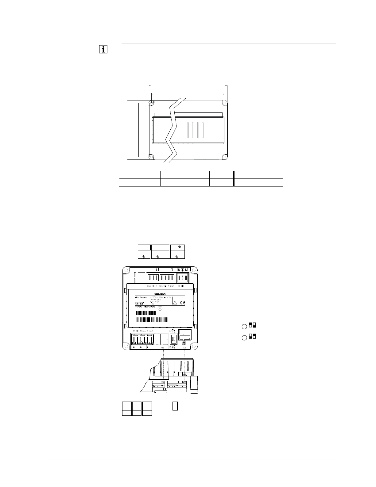
3.3.1 Connection terminals AVS75.390
S T N L
- - -
QX2
3
N
QX2
2
N
QX21
N L
050110A
000020
AVS75.390/109
1PAVS75.390/109
S050110000020
2359Z49
1
12
= module 2
2
1
2
= module 1
M
H2 M BX22 M BX21 - - - -
X30
n n n
21/258
Siemens Switzerland Ltd User manual RVS61.843, RVS41.813 CE1U2355en_02
HVAC Products 3 Mounting and installation 28. September 2009
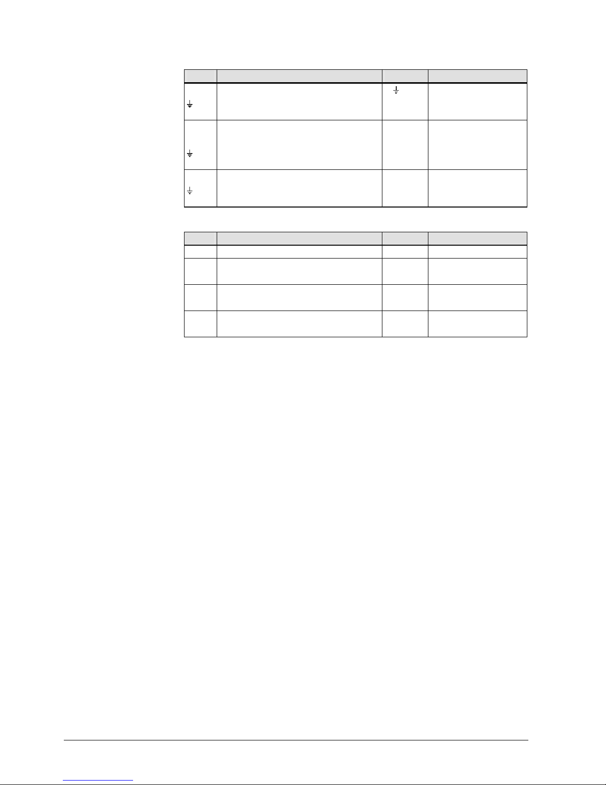
Terminal markings
Use Space Connector type
L Live AC 230 V basic unit N L AGP4S.03E/109
Protective earth
N Neutral conductor
QX21 Assignment according to function T AGP8S.04B/109
N Neutral conductor
Protective earth
QX22 Assignment according to function
N Neutral conductor S AGP8S.03B/109
Protective earth
QX23 Assignment according to function
Mains voltage
Use Space Connector type
Operator unit X30
AVS82.491/109
BX21 Assignment according to function AGP4S.02F/109
M Ground n
BX22 Assignment according to function AGP4S.02F/109
M Ground n
H2 Digital / 0...10 V input AGP4S.02F/109
M Ground n
Low
-voltage
Assignment of terminals
The 2 parameters
•
Function extension module 1 (operating line 6020)
• Function extension module 2 (6021)
are used to define usage of the respective module.
22/258
Siemens Switzerland Ltd User manual RVS61.843, RVS41.813 CE1U2355en_02
HVAC Products 3 Mounting and installation 28. September 2009
3.4 Operator unit AVS37.294
Mounting method
Mounting
Removal
2358Z30
2358Z31
2358Z32
Connections
The AVS37.2
94 operator unit must be connected to terminal X30 of the basic unit using
the AVS82.491/109 connecting cable.
The connectors are coded.
2358M03
144
96
90
27
42.4
17
Dim
ensions
(144)
0.5...3.0
92
+0.8
0
138
+1
0
2358M05
(96)
Panel cutout
23/258
Siemens Switzerland Ltd User manual RVS61.843, RVS41.813 CE1U2355en_02
HVAC Products 3 Mounting and installation 28. September 2009
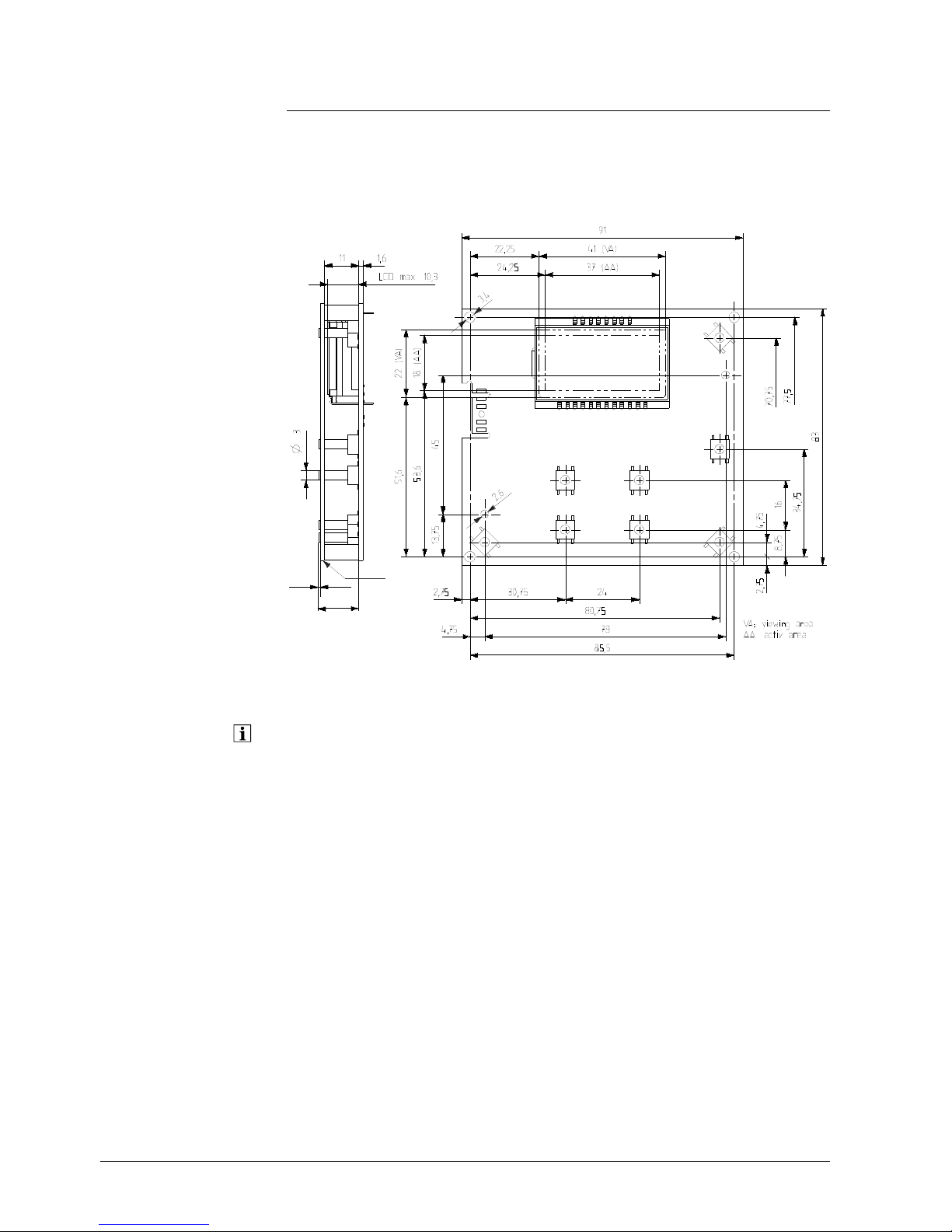
3.5 Operator unit AVS37.390
Connections
The AVS37.390 operator unit must be connected to terminal X30 of the basic unit using
the AVS82.491/109 connecting cable. The connectors are coded.
Dimensions
235 4M 01
13
0,5
A
A Control panel, front
The AVS37.3
90 operator unit is a PCB version without casing, supplied by Siemens.
24/258
Siemens Switzerland Ltd User manual RVS61.843, RVS41.813 CE1U2355en_02
HVAC Products 3 Mounting and installation 28. September 2009
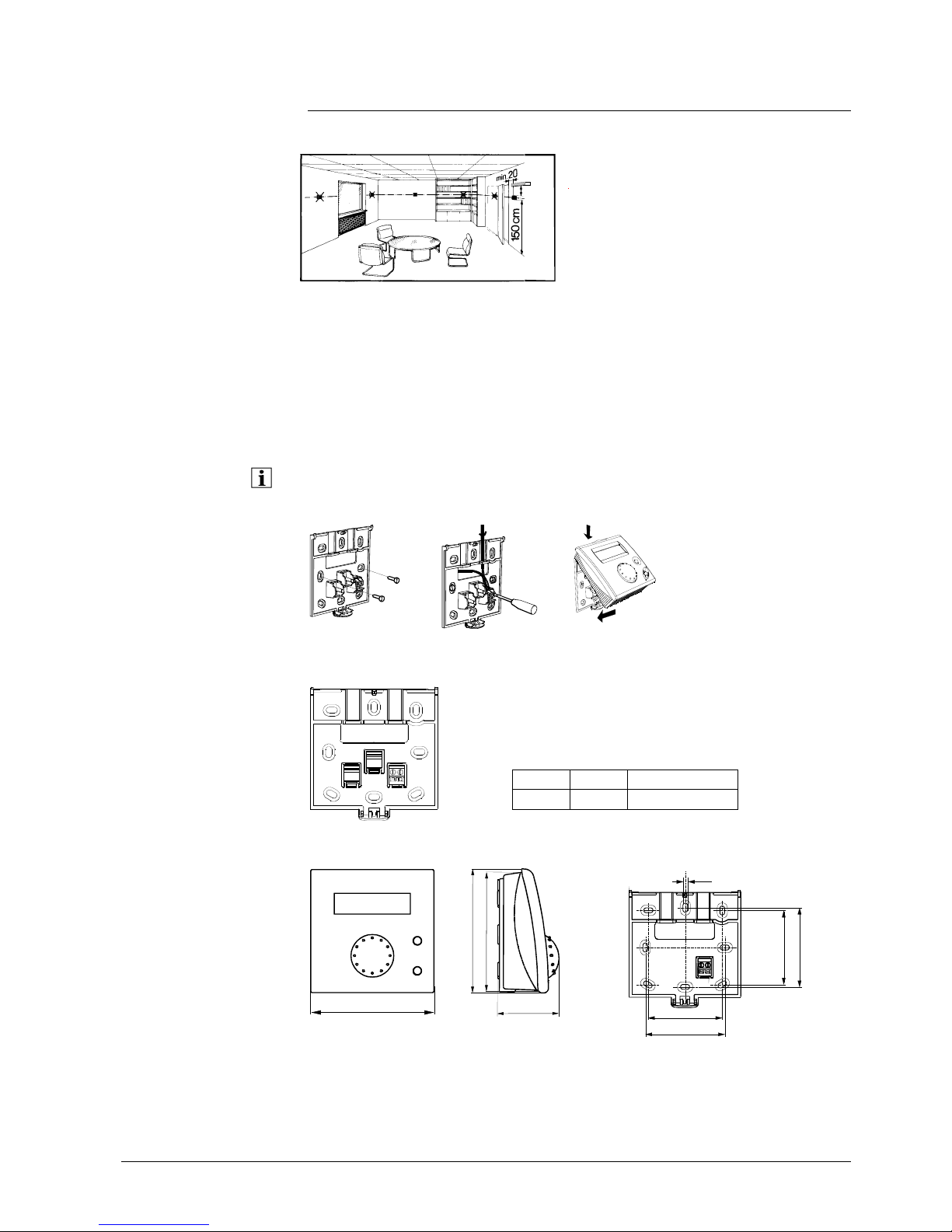
3.6 Room unit QAA55…
Engineering
min.
10 cm
2261Z03
The room unit should be located in the main living room while giving consideration to
the following criteria:
• The place of installation should be chosen so that the sensor can capture the room
temperature as accurately as possible without getting adversely affected by direct
solar radiation or other heat or refrigeration sources (about 1.5 meters above the
floor)
• In the case of wall mounting, there must be sufficient clearance above the unit,
enabling it to be fitted and removed
When the unit
is removed from its base, power is cut off so that the unit is out of
operation.
2284Z33a
2284Z34a
2284Z35a
Mounti
ng
•
The controller must not be exposed to dripping water
1
34
562
2284Z40
Connections
1 CL+ BSB data
2 CL- BSB ground
Dimensions and drilling plan
2284M02
96
9
6
9
1
4
7
12
2359Z27
4,2
56
60
56
60
25/258
Siemens Switzerland Ltd User manual RVS61.843, RVS41.813 CE1U2355en_02
HVAC Products 3 Mounting and installation 28. September 2009
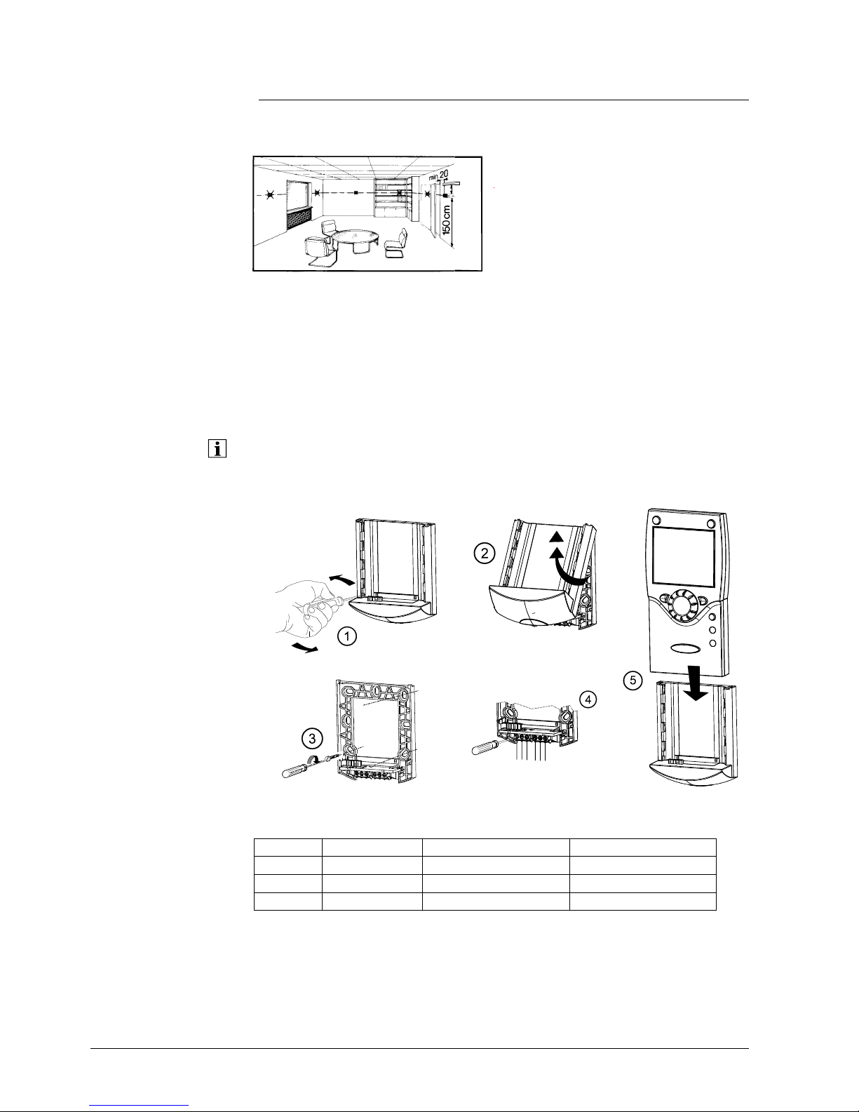
3.7 Room unit QAA75…
Engineering
min.
10 cm
2261Z03
The room unit should be located in the main living room while giving consideration to
the following criteria:
• The place of installation should be chosen so that the sensor can capture the room
temperature as accurately as possible without getting adversely affected by direct
solar radiation or other heat or refrigeration sources (about 1.5 meters above the
floor)
• In the case of wall mounting, there must be sufficient clearance above the unit,
enabling it to be fitted and removed
When the unit
is removed from its base, power is cut off so that the unit is out of
operation.
Mounti
ng method
2359Z21
2359Z25
2359Z20
2359Z26
2359Z24
Connections
Terminal Designation
QAA75.610 QAA75.611
1 CL+ BSB data BSB data
2 CL- BSB ground BSB ground
3 G+ Reserved Power supply DC 12 V
26/258
Siemens Switzerland Ltd User manual RVS61.843, RVS41.813 CE1U2355en_02
HVAC Products 3 Mounting and installation 28. September 2009
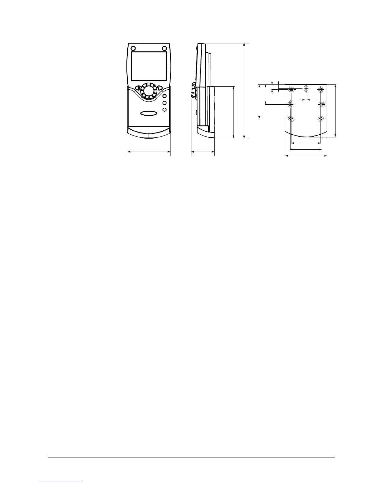
Dimensions and drilling plan
42
185
2359Z12
100
82
2359Z50
4,2
9
56
60
100
80
11
39
67
27/258
Siemens Switzerland Ltd User manual RVS61.843, RVS41.813 CE1U2355en_02
HVAC Products 3 Mounting and installation 28. September 2009
3.8 RF components
The wireless components should be located such that transmission is as interferencefree as possible. The following criteria must be observed:
• Not in the vicinity of electrical cables, strong magnetic fields or equipment, such as
PCs, TV sets, microwave ovens, etc.
• Not near larger metal structures or constructional elements with fine metal meshes,
such as special glass or special concrete
• The distance to the transmitter should not exceed 30 meters or 2 floors
3.8.1 RF module AVS71.390
The RF module extends the product range by introducing wireless communication. With
this type of device, the system components, such as room units, transmit data with no
need for laying cables.
E
ngineering Do not install t
he RF module inside metal casings (e.g. inside the heat pump).
2359Z23
Mounti
ng method
2359Z57
A
B
LED
Button
Connection The prefabricated cable is to
be connected to terminal X60 of the controller.
Prior to conne
cting the module, the basic unit must be disconnected from power!
Radio conne
ction Establishment
of the wireless connection is described in the following sections which
cover the relevant RF components.
43
2354Z11
Dimensions and drilling
plan
28/258
Siemens Switzerland Ltd User manual RVS61.843, RVS41.813 CE1U2355en_02
HVAC Products 3 Mounting and installation 28. September 2009
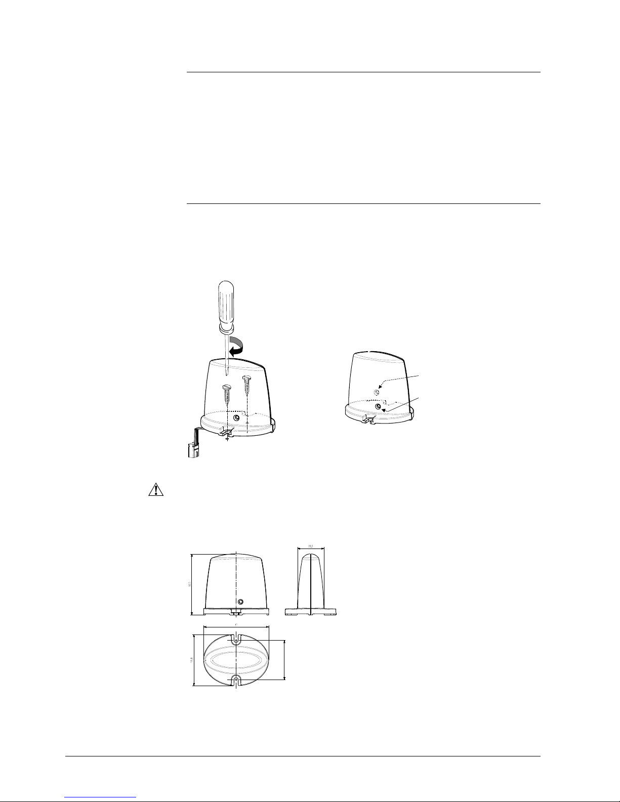
3.8.2 Room unit QAA78.610
Engineering
min.
10 cm
2261Z03
The room unit should be located in the main living room while giving consideration to
the following criteria:
• The place of installation should be chosen so that the sensor can capture the room
temperature as accurately as possible without getting adversely affected by direct
solar radiation or other heat or refrigeration sources (about 1.5 meters above the
floor)
• In the case of wall mounting, there must be sufficient clearance above the unit,
enabling it to be fitted and removed
Mounting with the
base
2359Z26
2359Z25
2359Z20
2359Z21
2359Z22
29/258
Siemens Switzerland Ltd User manual RVS61.843, RVS41.813 CE1U2355en_02
HVAC Products 3 Mounting and installation 28. September 2009
Mounting without the
base
2359Z61
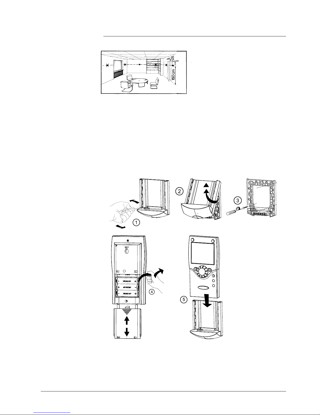
Connections / power supply
The room unit is po
wered by three 1.5 V Alkali batteries type AA (LR06).
Radio connection
Make the radio connection in the vicinity o
f the RF module prior to mounting so that all
system components are within easy reach.
Prerequisite for the radio connection is that all components receive power, which
means that the RF module must be correctly connected to the controller and the
batteries must be correctly installed in the room unit.
Establishment
1.
Press the button on the installed RF module for at least 8 seconds until the LED
on the module starts blinking at high frequency.
2. Press the OK button on the room unit to switch to programming.
3. Press the info button for at least 3 seconds and select operating level
"Commissioning" with the setting knob. Then, press the OK button.
4. Select menu "Wireless" and press the OK button.
5. Select operating line "Used as" (40) and make the appropriate selection. Then,
press the OK button.
6. Set the setting knob to "YES" and press the OK button. The process of opening
the connection is started.
7. The display shows the progress of opening the connection in %. This process
can take 2 to 120 seconds.
8. The connection is established when "Device ready" appears and the LED on the
RF module extinguishes
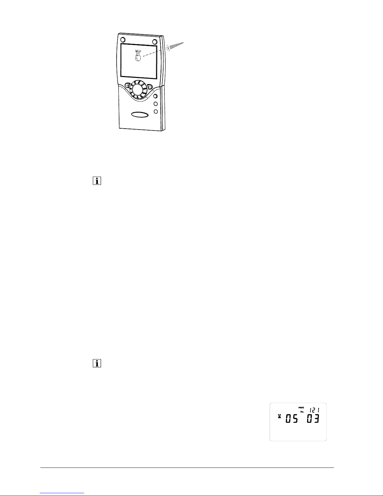
The test is made to check the quality of the radio link. Testing
• The test can be aborted by pressing the ESC button.
• While the radio link can be opened on the controller, the test should be made at the
location where the room unit will be installed
On the room unit, as described above (points 2 through 4), select menu "Radio" and
activate the test mode on setting line "Test mode" (121).
Example of a display during the test:
The digits on the left show telegrams that have
been sent, the digits on the right telegrams that
have been received. The test will be ended
after 24 telegrams. The test is considered
2359Z140
Oper ator s ect ion
Testmode
30/258
Siemens Switzerland Ltd User manual RVS61.843, RVS41.813 CE1U2355en_02
HVAC Products 3 Mounting and installation 28. September 2009
 Loading...