

Siemens RVP550,RVP540 Installation Instructions Manual
Siemens Building Technologies / HVAC Products 74 319 0312 0 a 19.08.2002 1/28
74 319 0312 0
G2488
en
Installation Instructions
Energy Manager / Heating Controller
RVP540
RVP550
Installation
Place of installation
• In a dry room, e.g. the boiler room
• Installation choices:
- Control panel (in the panel front, on the inner wall, or
on a DIN rail)
- Control cabinet
- Sloping front of a control desk
• Permissible ambient temperature: 0...50 °C
Electrical installation
• The local regulations for electrical installations must
be complied with
• Cable strain relief must be ensured
• Cables from the controller to the actuators and
pumps carry mains voltage
• Sensor cables should not be run parallel to mains car-
rying cables
• To protect the solar collector sensor from voltage
surges (caused by lightning for example), the separately
available conduit box for overvoltage protection
(AGS2S.200/109) should be installed
Permissible cable lengths
• For all sensors, thermostats and external contacts:
Copper cable 0.6 mm dia. max. 20 m
Copper cable 1.0 mm
2
max. 80 m
Copper cable 1.5 mm
2
max. 120 m
• For room units:
Copper cable 0.25 mm
2
max. 25 m
Copper cable 0.5 mm
2
max. 50 m
• For the data bus:
0.75...2.5 mm
2
according to Data Sheets
N2030E and N2032E
Mounting and wiring the base
Wall mounting
1. Separate base from the controller.
2. Hold base against the wall. Marking TOP must be at
the top!
3. Mark fixing holes on the wall.
4. Drill holes.
5. If required, knock out holes on the base for the cable
entry glands.
6. Screw base to the wall.
7. Wire up the base.
DIN rail mounting
1. Fit rail.
2. Separate base from the controller.
3. If required, knock out holes on the base for the cable
entry glands.
4. Fit base to the rail. Marking TOP must be at the top!
5. If required, secure the base (depending on the type of
rail).
6. Wire up the base.
Flush panel mounting
• Panel cutout required: 92 x 138 mm
• Maximum thickness: 3 mm
1. Separate base from the controller.
2. If required, knock out holes on the base for the cable
entry glands.
3. Insert base in the panel cutout from behind until stop
is reached. Marking TOP must be at the top!
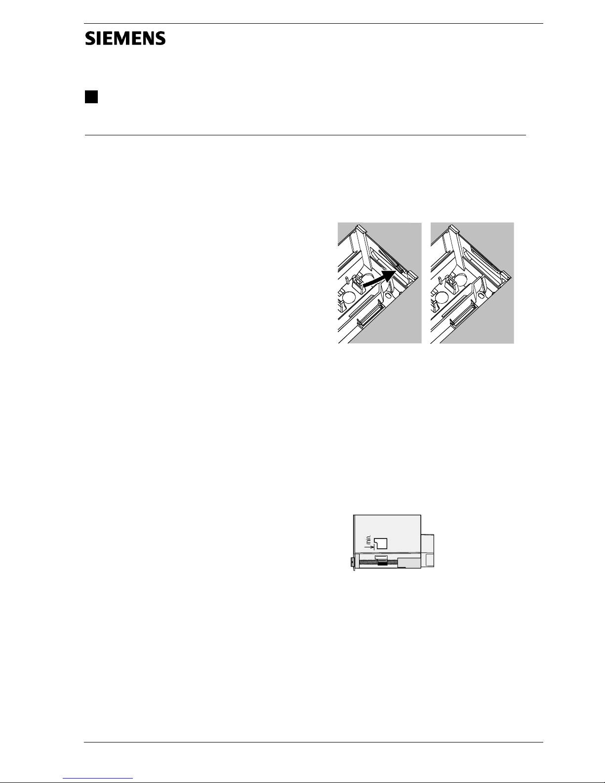
4. Push lateral tongues behind the front panel (refer to
illustration below).
2462Z06
Wrong Correct
Place tongues on both sides correctly – they may not be
located inside the cutout!
5. Wire up the base. Make sure the cable lengths are
such that there is sufficient space to open the control
panel door.
Commissioning
Preparatory checks
1. DO NOT switch on power yet.
2. Check wiring according to the plant connection diagram.
3. Ensure correct position and location of the levers by
turning the fixing screws (refer to illustration on the lateral wall of the unit).
2522Z13
4. Insert controller in the base until stop is reached.
Marking TOP must be at the top!
5. Tighten fixing screws alternately.
6. Check the motorized valves: See if
− they are correctly installed (observe direction of flow
as indicated on the valve body)
− the manual lever is disengaged.
7. Note with underfloor and ceiling heating systems:
The limit thermostat must be correctly adjusted. During
the functional test, the flow temperature may not exceed the maximum permissible level (usually 55 °C). If
it does, proceed immediately as follows:
- Either close the valve manually, or
- Switch off the pump, or
- Close the pump isolating valve
2/28 19.08.2002 74 319 0312 0 a Siemens Building Technologies / HVAC Products
8. Switch on power. The display must show something
(e.g. time of day). If not, the reason may be one of the
following:
- No mains voltage
- Main fuse blown
- Mains isolator or main switch not set to ON
9. If one of the operating mode buttons flashes, a room
unit or contact H1 overrides the controller. Select operating mode
on the room unit; switch off contact
H1.
General information about operation
• Setting elements:
− Setting knob
− Display; an operating line is assigned to each setting
− Buttons for selecting and adjusting setting values:
Next operating line below
Next operating line above
Decrease the displayed value
Increase the displayed value
• Adopting a setting value:
The setting value is adopted by selecting the next operating line (or by pressing one of the operating mode
buttons)
• Entering --.- / --:-- / --- (deactivating a function):
Keep
or depressed until the required display
appears
• Block jump function:
To select a single operating line quickly, 2 button
combinations can be used:
Press and to select the next line block above.
Press
and to select the next line block below.
Setting procedure
1. Make settings on the operating lines according to the
instructions provided by your local Siemens HVAC
Products sales office.
2. Select plant type on operating line 100.
3. Make the required settings on the controller. All functions and operating lines required for the selected type
of plant will be activated and can be set. Operating
lines that are not used will be hidden.
4. Enter the adjusted values in the table!
5. Set the general functions (independent of the type of
plant).
Commissioning and functional check
• Specific operating lines for the functional check:
200 = output test
201 = input test
296 = functional test oil- / gas-fired boiler
345 = functional test solar
395 = functional test wood-fired boiler
545 = functional test d.h.w. storage tank
745 = functional test heating circuit
888 = output test P1
894 = output test Ux
• If Er (ERROR) appears on the display: Refer to operating
line 50 to find the fault
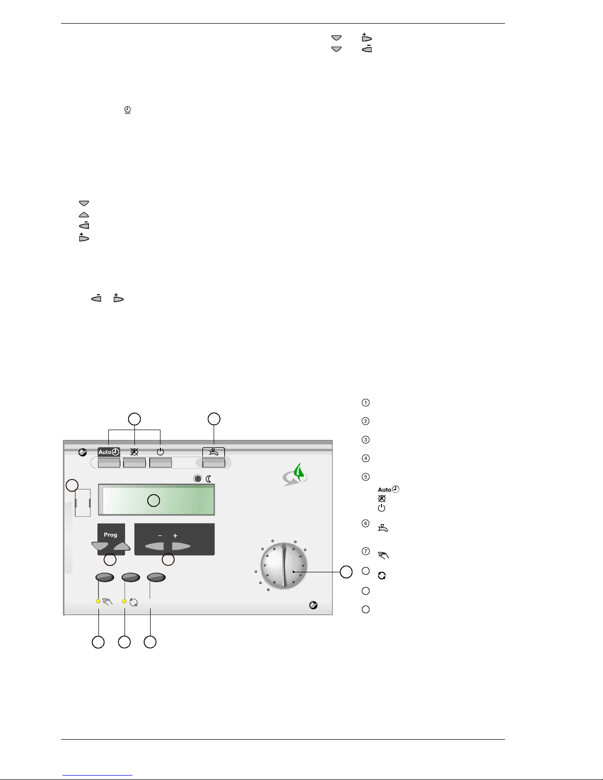
Operating elements
Room temperature setpoint knob
Adjustment of nominal room temperature setpoint
Setting buttons
Parameter settings (+ / -)
Operating line selection buttons (Prog)
Selection of parameters / switching operating lines
Display
Showing actual values and settings
Operating mode buttons heating circuit
Operating mode changes to:
Automatic operation
Continuous operation
Standby
Operating mode button d.h.w.
D.h.w. heating ON / OFF
Manual d.h.w. push
Function button with LED for manual operation
Manual operation ON / OFF
8
Green button with signal lamp
Green operation ON / OFF
9
Info button
Display of plant values
10
Connection facility for PC tool
Diagnostics and service with OCI69 / ACS69
An illuminated button or signal lamp indicates that the
relevant function is activated.
C
0 4 8 12 16 20 24
1 2 3 4 5 6 7 8 9 10
°C
20
26
14
Info
RVP540
6
5
4
1
7
8 9
2392 Z54a
10
3
2
Front of RVP540 and RVP550
Siemens Building Technologies / HVAC Products 74 319 0312 0 a 19.08.2002 3/28
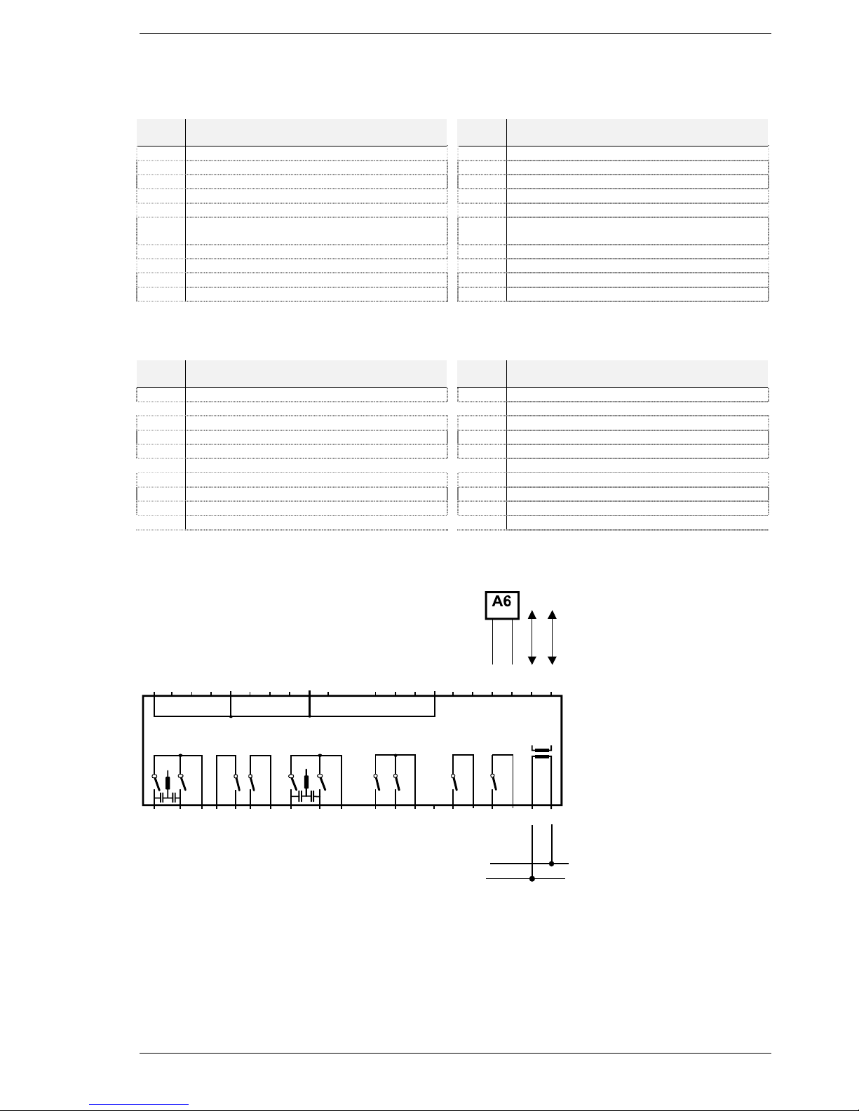
Connection diagrams
Markings of connection terminal on the low-voltage side
Terminal
Terminals Termi-
nal
Terminals
M Ground H1 Input H1 (contact or DC 0…10 V)
Ux Output DC 0…10 V B104 Temperature sensor
P1 PWM output B103 Temperature sensor
B109 Temperature sensor M Ground sensors
M Ground sensors B102 Temperature sensor
B108 Temperature sensor B101 Temperature sensor NTC / LG-Ni 1000
with automatic identification
B107 Temperature sensor MD Ground PPS (room unit, BMU)
B106 Temperature sensor A6 Data PPS (room unit, BMU)
M Ground sensors MB Ground bus (LPB)
B105 Temperature sensor DB Data bus (LPB)
Markings of connection terminal on the mains voltage side
Terminal
Terminals Termi-
nal
Terminals
Q110 Multifunctional output Q104 Multifunctional output
Q109 Multifunctional output Q103 Multifunctional output
F3 Phase Q109 / Q110 F1 Phase Q103 / Q104
F7 Phase Q108 E1 AC 230 V input
Q108 Multifunctional output Q102 Multifunctional output
Q107 Multifunctional output F5 Phase Q102
F6 Phase Q107 Q101 Multifunctional output
Q106 Multifunctional output F4 Phase Q101
Q105 Multifunctional output L Live conductor AC 230 V
F2 Phase Q105 / Q106 N Neutral conductor
Electrical connections
2392A03
M
B108
M
B105
H1
B104
B103
M
B106
B101
MD
A6
MB
DB
F2
N
Q105
Q106
F6
Q107
L
F4
Q101
F5
Q102
E1
F1
Q103
B107
Q104
B102
B109
Ux
M
Q108
F7
F3
Q109
Q110
P1
N
N
LPB
D1 D2
4/28 19.08.2002 74 319 0312 0 a Siemens Building Technologies / HVAC Products
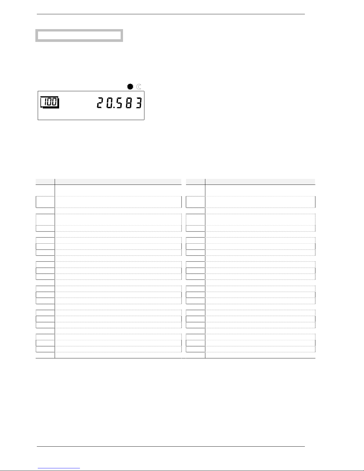
Selection
Selecting the plant type:
Select the required type of plant (basic diagram number) on operating line 100 (refer to page 8). The selection activates all
functions that are required for the specific plant and shows the operating lines needed.
In addition, operating parameters 120 through 173 will be set to their default values required for the basic plant.
During the setting procedure, the basic diagram number on the display flashes. The required number must be confirmed by
pressing the + / - buttons twice for 3 seconds. Then, the basic diagram number will stop flashing.
Example:
2392a04
04
8 12162024
123
4567
89
10
Plant type
The basic plant diagram for the required type of plant and additional setting information will be provided by your local
Siemens Building Technologies / HVAC Products sales office.
Designations of relays and sensors
The relay designations used in the supplied basic diagram have the following meaning:
Relays Function (use) Relays Function (use)
K1 Heat pump stage 1 Y7 Maintained boiler return temperature, oil / gas
OPEN
K2 Heat pump stage 2 Y8 Maintained boiler return temperature, oil / gas
CLOSED
K3 Release of external wood-fired boiler Y9 Maintained boiler return temperature, wood OPEN
K4 Oil- / gas-fired boiler, stage 1 Y10 Maintained boiler return temperature, wood
CLOSED
K5 Oil- / gas-fired boiler, stage 2 Y14 Diverting valve partial storage tank charging
K6 Electric immersion heater for d.h.w. Y¯14 Inverted Y14 signal
K8 Solar collector pump or diverting valve heat exchanger 2 Y15 Diverting valve for return
K¯8 Inverted K8 signal Y¯15 Inverted Y15 signal
K9 Solar bypass valve or heat exchanger pump Q1 Boiler pump of oil- / gas-fired boiler
K¯9 Inverted K9 signal Q2 Heating circuit pump
K10 Alarm output Q3 D.h.w. charging pump
K11 Overtemperature protection Q¯3 Inverted Q3 signal
K¯11 Inverted K11 signal Q4 D.h.w. circulating pump
K12 Solar collector pump or diverting valve heat exchanger 1 Q5 Solar collector pump 1
K13 Output K13 for free time switch program Q9 Heat pump circulator
K14 Release of external oil- / gas-fired boiler Q10 Pump of wood-fired boiler
K15 Release of external heat pump Q11 Storage tank heat transfer pump
K16 Electric immersion heater for buffer storage tank Q12 Oil / gas bypass pump
K17 Flue gas temperature sensor function Q13 D.h.w. storage tank heat transfer pump
K18 Output for solar swimming pool heating Q14 System pump
K¯18 Inverted K18 signal Q15 Pump H1
Y1 Heating circuit mixing valve OPEN Q16 Solar collector pump 2
Y2 Heating circuit mixing valve CLOSED Q17 Additional pump Q17 for heat pump stage 2
Y3 Diverting valve d.h.w. E1 Mains input
Y4 Heat generation lock L Live conductor (mains connection)
Y¯4 Inverted Y4 signal N Neutral conductor (mains connection)
Siemens Building Technologies / HVAC Products 74 319 0312 0 a 19.08.2002 5/28
Sensor designations
The sensor designations used in the supplied basic diagram have the following meaning:
Sensor Function (use) Types of
sensors
Sensor Function (use) Types of sen-
sors
B1 Heating circuit flow sensor LG-Ni 1000 B7 Return sensor oil / gas LG-Ni 1000
B2 Sensor of oil- / gas-fired boiler LG-Ni 1000 B71 Return sensor heat pump LG-Ni 1000
B21 Heat pump flow sensor LG-Ni 1000 B72 Return sensor wood LG-Ni 1000
B22 Sensor of wood-fired boiler LG-Ni 1000 B73 Return sensor heating circuit LG-Ni 1000
B3 D.h.w. sensor 1 LG-Ni 1000 B8 Flue gas sensor Pt 1000
B31 D.h.w. sensor 2 LG-Ni 1000 B9 Outside sensor LG-Ni 1000
NTC 600
B32 D.h.w. sensor 3 LG-Ni 1000 B10 Common flow sensor LG-Ni 1000
B33 D.h.w. sensor 4 LG-Ni 1000 B13 Sensor for solar swimming pool
heating
LG-Ni 1000
B4 Buffer storage tank sensor 1 LG-Ni 1000 M Ground sensors H1, U1, P1 –
B41 Buffer storage tank sensor 2 LG-Ni 1000 H1 Contact or DC 0…10 V input –
B42 Buffer storage tank sensor 3 LG-Ni 1000 U1 DC 0…10 V output –
B43 Buffer storage tank sensor 4 LG-Ni 1000 P1 PWM output –
B6 Solar collector sensor 1 LG-Ni 1000 /
Pt 1000
A6 PPS data –
B61 Solar collector sensor 2 LG-Ni 1000 /
Pt 1000
MD PPS ground –
B62 Solar collector flow sensor DB LPB data
B63 Solar flow sensor for yield measurement LG-Ni 1000 MB LPB ground
B64 Solar return sensor for yield measure-
ment
LG-Ni 1000 –
Parameter list
Settings to be made on the «Enduser» level
Settings that meet individual enduser needs.
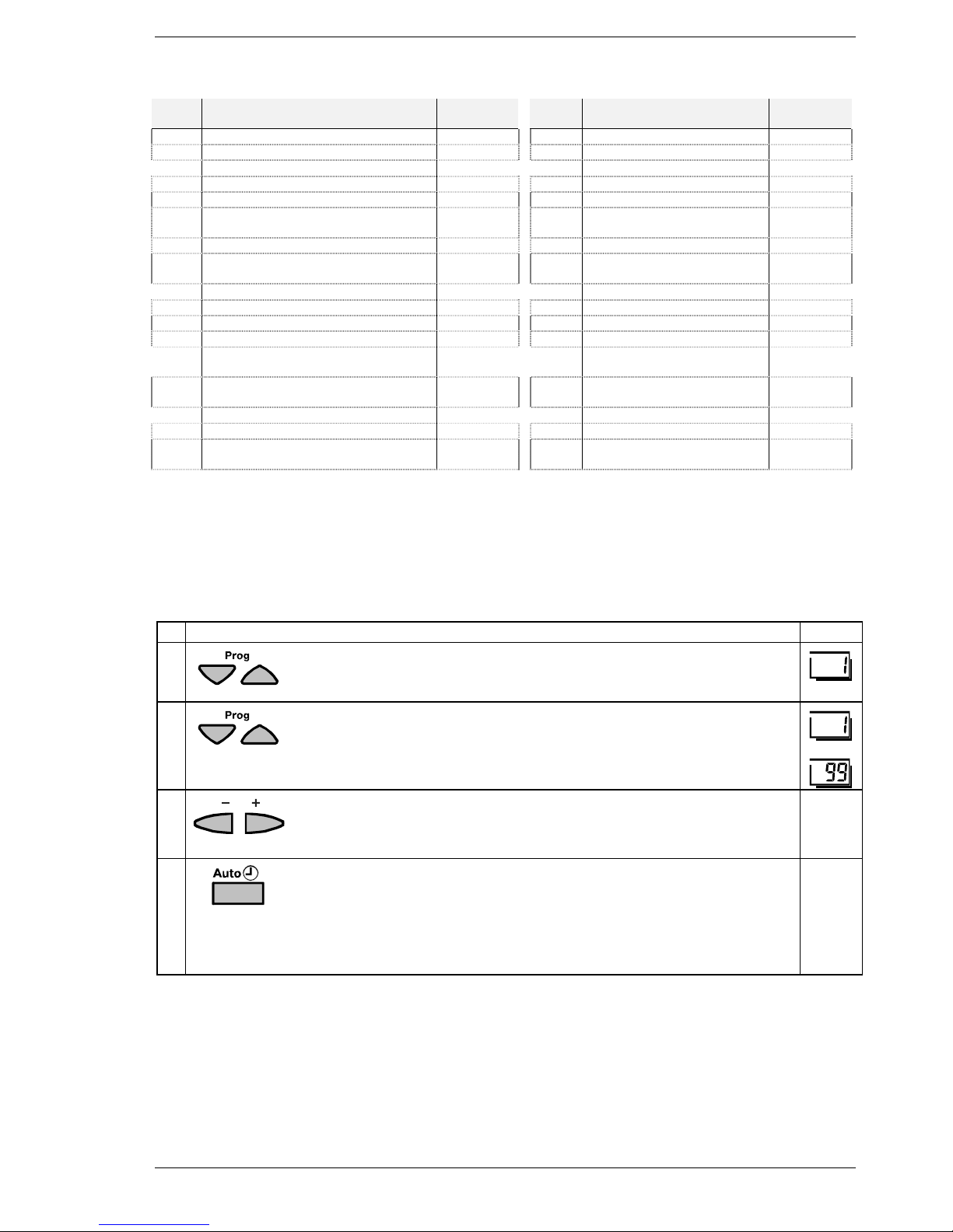
Buttons Explanation Line
1
Press one of the operating line selection buttons.
This will take you directly to programming mode “Enduser“.
2
Press the operating line selection buttons to select the required operating line.
The following parameter list contains all settings that can be made.
• • •
3
Press the + or – button to set the required value.
The setting will be stored as soon as you leave the programming mode or
change to another line.
4
To leave programming mode “Enduser“, press any of the operating mode buttons.
è Note:
If no button is pressed for about 8 minutes, the controller will automatically return to the operating mode selected last.
Continuous
display

6/28 19.08.2002 74 319 0312 0 a Siemens Building Technologies / HVAC Products
Overview of the enduser parameters
Line Function Range Unit Resolution Factory
setting
Setting the clock
1 Time of day 00:00...23:59 h / min .... : .... –
2 Weekday 1...7 Day ...... day –
3 Date 01.01...31.12 Day /
month
.... : .... –
4 Year 2001...2094 Year ...... year –
Time switch program for the heating circuit
5 Weekday – preselection heating circuit
1-7 7-day block
1...7 Individual days
1-7 / 1...7 Day ...... day –
6 Switch-on time 1st period heating circuit 00:00...24:00 h / min .... : ....
h / min
06:00
7 Switch-off time 1st period heating circuit 00:00...24:00 h / min .... : ....
h / min
22:00
8 Switch-on time 2nd period heating circuit 00:00...24:00 h / min .... : ....
h / min
- -:- -
9 Switch-off time 2nd period heating circuit 00:00...24:00 h / min .... : ....
h / min
- -:- -
10 Switch-on time 3rd period heating circuit 00:00...24:00 h / min .... : ....
h / min
- -:- -
11 Switch-off time 3rd period heating circuit 00:00...24:00 h / min .... : ....
h / min
- -:- -
Free time switch program
12 Weekday – preselection free time switch program
1-7 7-day lock
1...7 Individual days
1-7 / 1...7 Day ...... day –
13 Switch-on time 1st period free time switch pr. 00:00...24:00 h / min .... : ....
h / min
06:00
14 Switch-off time 1st period free time switch pr. 00:00...24:00 h / min .... : ....
h / min
22:00
15 Switch-on time 2nd period free time switch pr. 00:00...24:00 h / min .... : ....
h / min
- -:- -
16 Switch-off time 2nd period free time switch pr. 00:00...24:00 h / min .... : ....
h / min
- -:- -
17 Switch-on time 3rd period free time switch pr. 00:00...24:00 h / min .... : ....
h / min
- -:- -
18 Switch-off time 3rd period free time switch pr. 00:00...24:00 h / min .... : ....
h / min
- -:- -
Time switch program for d.h.w. heating
19 Weekday – preselection d.h.w.
1-7 7-day block
1...7 Individual days
1-7 / 1...7 Day ...... day –
20 Switch-on time 1st period d.h.w. 00:00...24:00 h / min .... : ....
h / min
06:00
21 Switch-off time 1st period d.h.w. 00:00...24:00 h / min .... : ....
h / min
22:00
22 Switch-on time 2nd period d.h.w. 00:00...24:00 h / min .... : ....
h / min
- -:- -
23 Switch-off time 2nd period d.h.w. 00:00...24:00 h / min .... : ....
h / min
- -:- -
24 Switch-on time 3rd period d.h.w. 00:00...24:00 h / min .... : ....
h / min
- -:- -
25 Switch-off time 3rd period d.h.w. 00:00...24:00 h / min .... : ....
h / min
- -:- -

Siemens Building Technologies / HVAC Products 74 319 0312 0 a 19.08.2002 7/28
Line Function Range Unit Resolution Factory
setting
D.h.w. values
26 Nominal setpoint of the d.h.w. temperature (TBWw)
TBWR Line 770
TBWmax Line 750
EXP
TBWR...TBW
max
°C ...... °C 55
Heating circuit values
27 Reduced setpoint of the room temperature (TRRw)
TRF Line 28
TRN Setpoint knob
TRF...TRN °C ...... °C 16
28 Frost protection setpoint of the room temperature
(TRFw)
TRR Line 27
4...TRR °C ...... °C 10
29 Summer / winter changeover temperature 8...30 °C ...... °C 17
30 Slope of the heating curve 1.0...40 – ...... 15
33 Actual value of the room temperature (TRx) 0...50 °C – –
General
34 Actual value of the outside temperature (TAx)
To set the attenuated outside temperature to Tax, press the + / buttons simultaneously for 3 s
-50...+50 °C – –
38 Resetting the enduser parameters
To reset the parameters of the enduser level to their standard
values, press the + / - buttons simultaneously for 3 s
0 / 1 – – 0
39 Resetting the heating circuit and d.h.w. time switch
programs
To reset the time switch programs of the enduser level to their
standard values, press the + / - buttons simultaneously for 3 s
0 / 1 – – 0
Holiday program
40 Preselection of the holiday period 1...8 – ...... 1
41 Beginning of the holiday period
--.-- Inactive
To deactivate the set holiday period, press the + / - buttons simultaneously for 3 s
--.-- /
01.01...31.12
Day /
month
.... . ....
day /
month
--.--
42 End of the holiday period
--.-- Inactive
To deactivate the set holiday period, press the + / - buttons simultaneously for 3 s
--.-- /
01.01...31.12
Day /
month
.... . ....
day /
month
--.--
General / service
50 Indication of error signals
No display = no fault
10 = fault outside sensor
20 = fault boiler sensor oil / gas B2
25 = fault boiler sensor wood B22
26 = fault common flow sensor B10
28 = fault flue gas sensor B8
30 = fault flow sensor heating circuit B1
33 = fault flow sensor heat pump B21
40 = fault return sensor oil / gas B7
43 = fault return sensor wood B72
44 = fault return sensor heat pump B71
47 = fault common return sensor B73
50 = fault storage tank sensor / thermostat B3
52 = fault storage tank sensor / thermostat B31
55 = fault storage tank sensor / thermostat B32
56 = fault storage tank sensor / thermostat B33
61 = fault room unit
70 = fault storage tank sensor B4
71 = fault storage tank sensor B41
72 = fault storage tank sensor B42
73 = fault collector sensor B6
74 = fault collector sensor B61
75 = fault solar flow sensor B62
76 = fault storage tank sensor B43
79 = fault water / brine sensor B11
81 = short-circuit data bus (LPB)
82 = same bus address exists several times
86 = short-circuit PPS
100 = 2 clock time masters on the data bus (LPB)
127 = legionella temperature not reached
130 = maximum flue gas temperature exceeded
8/28 19.08.2002 74 319 0312 0 a Siemens Building Technologies / HVAC Products
Line Function Range Unit Resolution Factory
setting
134 = fault heat pump at input H1
135 = water / brine temperature too low
137 = fault heat pump at input E1
138 = fault control sensor heat pump (operating line 420)
145 = wrong PPS unit (BMU / room unit)
146 = configuration error (operating line 202)
147 = external heat source missing (PPS / LPB)
150 = fault BMU
171 = alarm signal at input H1
172 = alarm signal at input E1
211 = fault wood-fired boiler
231-239 = fault sensor input B101 - B109
241 = fault flow sensor yield measurement B63
242 = fault return sensor measurement B64
243 = fault swimming pool sensor B13
Oil- or gas-fired boiler
60 Chimney sweep
0 = OFF
1 = ON
Outside the programming level, the + / - buttons can be used to
activate / deactivate the second burner stage
0 / 1 – – 0
Solar collectors
65 24-hour yield solar energy 0...999.9 kWh – 0
66 Total yield solar energy
To reset the total yield to 0, press the + / - buttons simultaneously
for 3 s
0...9999999.9 kWh – 0
Heat pump
75 Acknowledgement of heat pump error messages
135 and 137
To reset the error messages to 0, press the + / - buttons simultaneously for 3 s
0 / 1 – – 0
Settings to be made on the «Heating engineer» level
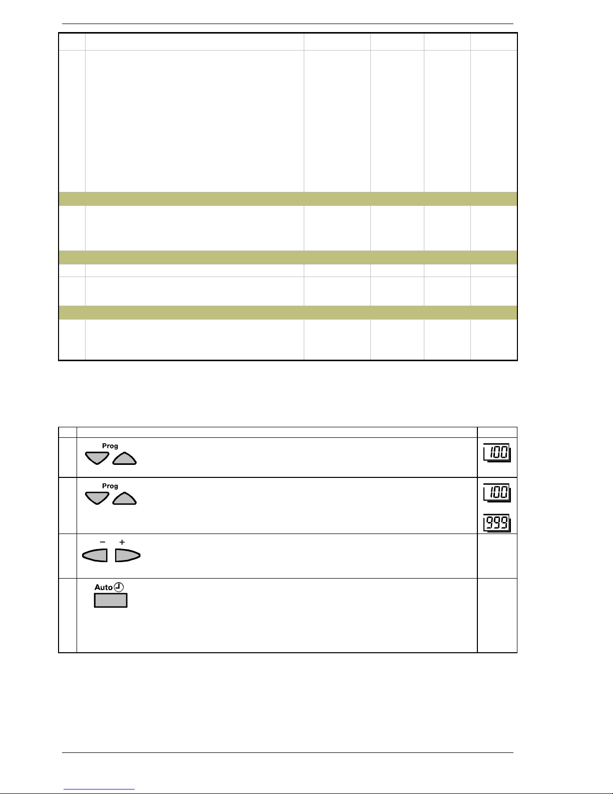
Settings required for the configuration and parameterization by the heating engineer.
Buttons Explanation Line
1
Press both operating line selection buttons for at least 3 seconds.
This will take you to programming level “Enduser”.
2
Press the operating line selection buttons to select the required operating line.
The parameter list on the next pages contains all operating lines on which settings can be made.
• • •
3
Press the + or – button to set the required value.
The setting will be stored as soon as you leave the programming mode or
change to another operating line.
4
To leave programming level “Heating engineer“, press one of the operating
mode buttons.
è Note:
If no button is pressed for about 8 minutes, the controller will automatically return
to the operating mode selected last.
Continuous
display

Siemens Building Technologies / HVAC Products 74 319 0312 0 a 19.08.2002 9/28
Overview of the heating engineer parameters
Line Function Range Unit Resolution Factory
setting
General / service
Basic diagrams
100 Selection of the basic diagram
0
No basic diagram selected
1...99.998 Basic diagrams
To adopt the selected diagram number, press the + / - buttons simultaneously for 3 s
0...99.998 – ...... 0
Configuration
Partial diagrams
120 Selection of partial diagram oil- / gas-fired boiler
0
Partial diagram inactive (OeG0)
1...9 Partial diagrams OeG1 through OeG9
0...9 – ...... 0
121 Selection of partial diagram solar collectors
0
Partial diagram inactive (OeG0)
1...16 Partial diagrams Sol1 through Sol16
0...16 – ...... 0
122 Selection of partial diagram wood-fired boiler
0 Partial diagram inactive (Ho0)
1...5 Partial diagrams Ho1 through Ho5
0...5 – ...... 0
123 Selection of partial diagram heat pump
0 Partial diagram inactive (Wp0)
1...5
Partial diagrams Wp1 through Wp5
0...5 – ...... 0
124 Display of partial diagram buffer storage tank
0 Partial diagram inactive (Sp0)
1...3 Partial diagrams Sp1 through Sp3
0...3 – ...... 0
125 Display of partial diagram d.h.w. storage tank
0 Partial diagram inactive (BwSp0)
1...10 Partial diagrams BwSp1 through BwSp10
0...10 – ...... 0
126 Selection of partical diagram combi storage tank
0 Partial diagram inactive (KoSp0)
1...6 Partial diagrams KoSp1 through KoSp6
0...6 – ...... 0
127 Selection of partial diagram heating circuit
0 Partial diagram inactive (Rh0)
1...3 Partial diagrams Rh1 through Rh3
0...3 – ...... 0
Hiding sensors that are not required
130 Source outside sensor
0 Signal via bus (PPS or LPB)
1 Signal via terminal
0 / 1 – ...... 0
131 Reduction 1st d.h.w. sensor B3
0 Without sensor B3
1 With sensor B3
0 / 1 – ...... 0
132 Reduction 2nd d.h.w. sensor B31
0 Without sensor B31
1 With sensor B31
0 / 1 – ...... 0
133 Reduction 2nd buffer storage tank sensor B41
0 Without sensor B41
1 With sensor B41
0 / 1 – ...... 0
135 Reduction wood-fired boiler return sensor B72
0 Without sensor B72
1 With sensor B72
0 / 1 – ...... 0
136 Reduction heat pump flow sensor B21
0 Without sensor B21
1 With sensor B21
0 / 1 – ...... 0
137 Reduction heat pump return sensor B71
0 Without sensor B71
1 With sensor B71
0 / 1 – ...... 0
138 Reduction water / brine sensor B11
0 Without sensor B11
1 With sensor B11
0 / 1 – ...... 0
 Loading...