

Page 1
Siemens Building Technologies / HVAC Products 74 319 0312 0 a 19.08.2002 1/28
74 319 0312 0
G2488
en
Installation Instructions
Energy Manager / Heating Controller
RVP540
RVP550
Installation
Place of installation
• In a dry room, e.g. the boiler room
• Installation choices:
- Control panel (in the panel front, on the inner wall, or
on a DIN rail)
- Control cabinet
- Sloping front of a control desk
• Permissible ambient temperature: 0...50 °C
Electrical installation
• The local regulations for electrical installations must
be complied with
• Cable strain relief must be ensured
• Cables from the controller to the actuators and
pumps carry mains voltage
• Sensor cables should not be run parallel to mains car-
rying cables
• To protect the solar collector sensor from voltage
surges (caused by lightning for example), the separately
available conduit box for overvoltage protection
(AGS2S.200/109) should be installed
Permissible cable lengths
• For all sensors, thermostats and external contacts:
Copper cable 0.6 mm dia. max. 20 m
Copper cable 1.0 mm
2
max. 80 m
Copper cable 1.5 mm
2
max. 120 m
• For room units:
Copper cable 0.25 mm
2
max. 25 m
Copper cable 0.5 mm
2
max. 50 m
• For the data bus:
0.75...2.5 mm
2
according to Data Sheets
N2030E and N2032E
Mounting and wiring the base
Wall mounting
1. Separate base from the controller.
2. Hold base against the wall. Marking TOP must be at
the top!
3. Mark fixing holes on the wall.
4. Drill holes.
5. If required, knock out holes on the base for the cable
entry glands.
6. Screw base to the wall.
7. Wire up the base.
DIN rail mounting
1. Fit rail.
2. Separate base from the controller.
3. If required, knock out holes on the base for the cable
entry glands.
4. Fit base to the rail. Marking TOP must be at the top!
5. If required, secure the base (depending on the type of
rail).
6. Wire up the base.
Flush panel mounting
• Panel cutout required: 92 x 138 mm
• Maximum thickness: 3 mm
1. Separate base from the controller.
2. If required, knock out holes on the base for the cable
entry glands.
3. Insert base in the panel cutout from behind until stop
is reached. Marking TOP must be at the top!
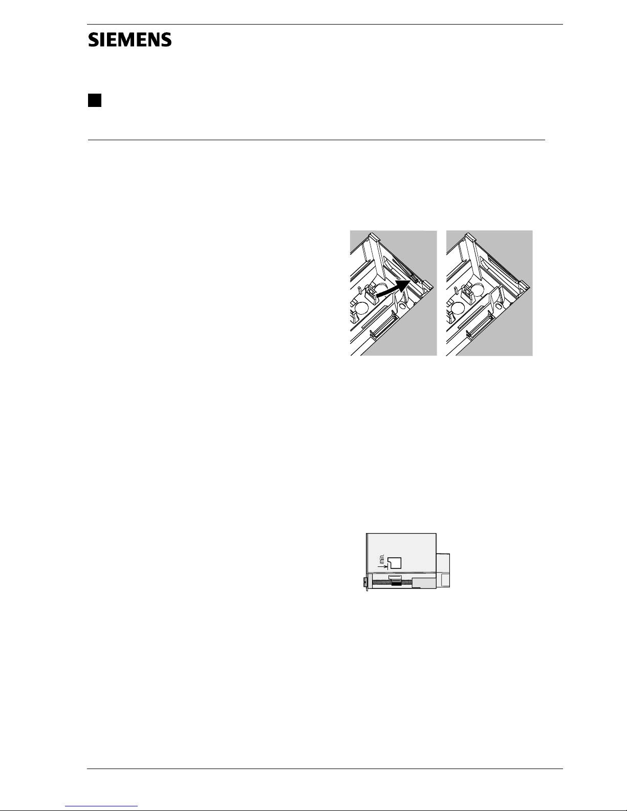
4. Push lateral tongues behind the front panel (refer to
illustration below).
2462Z06
Wrong Correct
Place tongues on both sides correctly – they may not be
located inside the cutout!
5. Wire up the base. Make sure the cable lengths are
such that there is sufficient space to open the control
panel door.
Commissioning
Preparatory checks
1. DO NOT switch on power yet.
2. Check wiring according to the plant connection diagram.
3. Ensure correct position and location of the levers by
turning the fixing screws (refer to illustration on the lateral wall of the unit).
2522Z13
4. Insert controller in the base until stop is reached.
Marking TOP must be at the top!
5. Tighten fixing screws alternately.
6. Check the motorized valves: See if
− they are correctly installed (observe direction of flow
as indicated on the valve body)
− the manual lever is disengaged.
7. Note with underfloor and ceiling heating systems:
The limit thermostat must be correctly adjusted. During
the functional test, the flow temperature may not exceed the maximum permissible level (usually 55 °C). If
it does, proceed immediately as follows:
- Either close the valve manually, or
- Switch off the pump, or
- Close the pump isolating valve
Page 2
2/28 19.08.2002 74 319 0312 0 a Siemens Building Technologies / HVAC Products
8. Switch on power. The display must show something
(e.g. time of day). If not, the reason may be one of the
following:
- No mains voltage
- Main fuse blown
- Mains isolator or main switch not set to ON
9. If one of the operating mode buttons flashes, a room
unit or contact H1 overrides the controller. Select operating mode
on the room unit; switch off contact
H1.
General information about operation
• Setting elements:
− Setting knob
− Display; an operating line is assigned to each setting
− Buttons for selecting and adjusting setting values:
Next operating line below
Next operating line above
Decrease the displayed value
Increase the displayed value
• Adopting a setting value:
The setting value is adopted by selecting the next operating line (or by pressing one of the operating mode
buttons)
• Entering --.- / --:-- / --- (deactivating a function):
Keep
or depressed until the required display
appears
• Block jump function:
To select a single operating line quickly, 2 button
combinations can be used:
Press and to select the next line block above.
Press
and to select the next line block below.
Setting procedure
1. Make settings on the operating lines according to the
instructions provided by your local Siemens HVAC
Products sales office.
2. Select plant type on operating line 100.
3. Make the required settings on the controller. All functions and operating lines required for the selected type
of plant will be activated and can be set. Operating
lines that are not used will be hidden.
4. Enter the adjusted values in the table!
5. Set the general functions (independent of the type of
plant).
Commissioning and functional check
• Specific operating lines for the functional check:
200 = output test
201 = input test
296 = functional test oil- / gas-fired boiler
345 = functional test solar
395 = functional test wood-fired boiler
545 = functional test d.h.w. storage tank
745 = functional test heating circuit
888 = output test P1
894 = output test Ux
• If Er (ERROR) appears on the display: Refer to operating
line 50 to find the fault
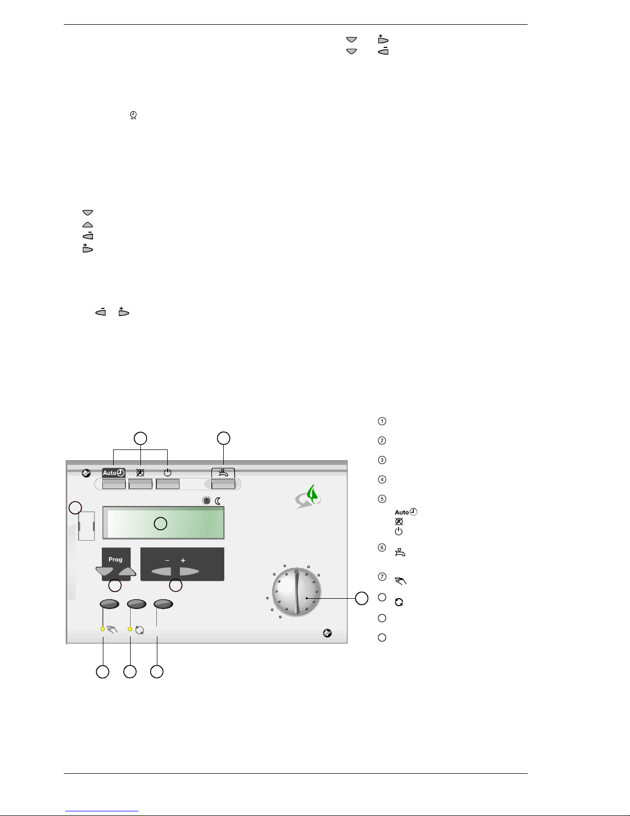
Operating elements
Room temperature setpoint knob
Adjustment of nominal room temperature setpoint
Setting buttons
Parameter settings (+ / -)
Operating line selection buttons (Prog)
Selection of parameters / switching operating lines
Display
Showing actual values and settings
Operating mode buttons heating circuit
Operating mode changes to:
Automatic operation
Continuous operation
Standby
Operating mode button d.h.w.
D.h.w. heating ON / OFF
Manual d.h.w. push
Function button with LED for manual operation
Manual operation ON / OFF
8
Green button with signal lamp
Green operation ON / OFF
9
Info button
Display of plant values
10
Connection facility for PC tool
Diagnostics and service with OCI69 / ACS69
An illuminated button or signal lamp indicates that the
relevant function is activated.
C
0 4 8 12 16 20 24
1 2 3 4 5 6 7 8 9 10
°C
20
26
14
Info
RVP540
6
5
4
1
7
8 9
2392 Z54a
10
3
2
Front of RVP540 and RVP550
Page 3
Siemens Building Technologies / HVAC Products 74 319 0312 0 a 19.08.2002 3/28
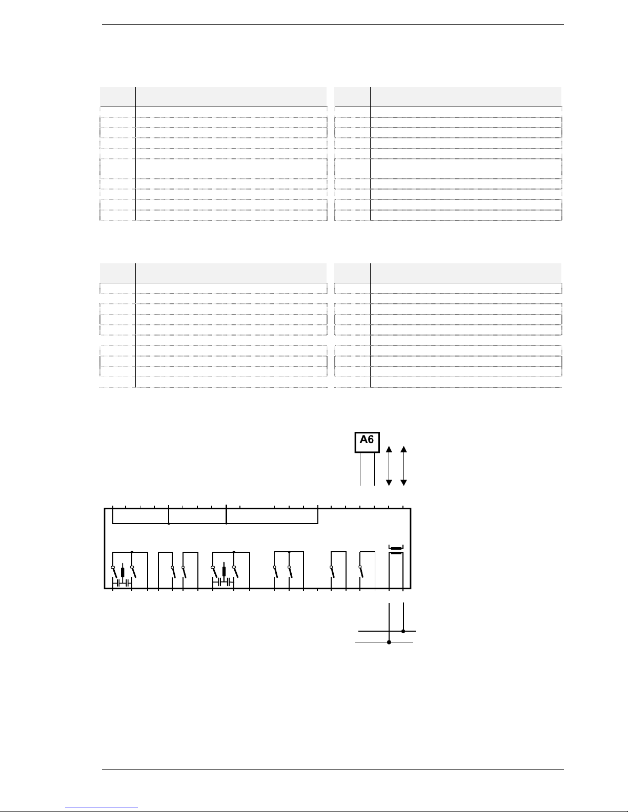
Connection diagrams
Markings of connection terminal on the low-voltage side
Terminal
Terminals Termi-
nal
Terminals
M Ground H1 Input H1 (contact or DC 0…10 V)
Ux Output DC 0…10 V B104 Temperature sensor
P1 PWM output B103 Temperature sensor
B109 Temperature sensor M Ground sensors
M Ground sensors B102 Temperature sensor
B108 Temperature sensor B101 Temperature sensor NTC / LG-Ni 1000
with automatic identification
B107 Temperature sensor MD Ground PPS (room unit, BMU)
B106 Temperature sensor A6 Data PPS (room unit, BMU)
M Ground sensors MB Ground bus (LPB)
B105 Temperature sensor DB Data bus (LPB)
Markings of connection terminal on the mains voltage side
Terminal
Terminals Termi-
nal
Terminals
Q110 Multifunctional output Q104 Multifunctional output
Q109 Multifunctional output Q103 Multifunctional output
F3 Phase Q109 / Q110 F1 Phase Q103 / Q104
F7 Phase Q108 E1 AC 230 V input
Q108 Multifunctional output Q102 Multifunctional output
Q107 Multifunctional output F5 Phase Q102
F6 Phase Q107 Q101 Multifunctional output
Q106 Multifunctional output F4 Phase Q101
Q105 Multifunctional output L Live conductor AC 230 V
F2 Phase Q105 / Q106 N Neutral conductor
Electrical connections
2392A03
M
B108
M
B105
H1
B104
B103
M
B106
B101
MD
A6
MB
DB
F2
N
Q105
Q106
F6
Q107
L
F4
Q101
F5
Q102
E1
F1
Q103
B107
Q104
B102
B109
Ux
M
Q108
F7
F3
Q109
Q110
P1
N
N
LPB
D1 D2
Page 4
4/28 19.08.2002 74 319 0312 0 a Siemens Building Technologies / HVAC Products
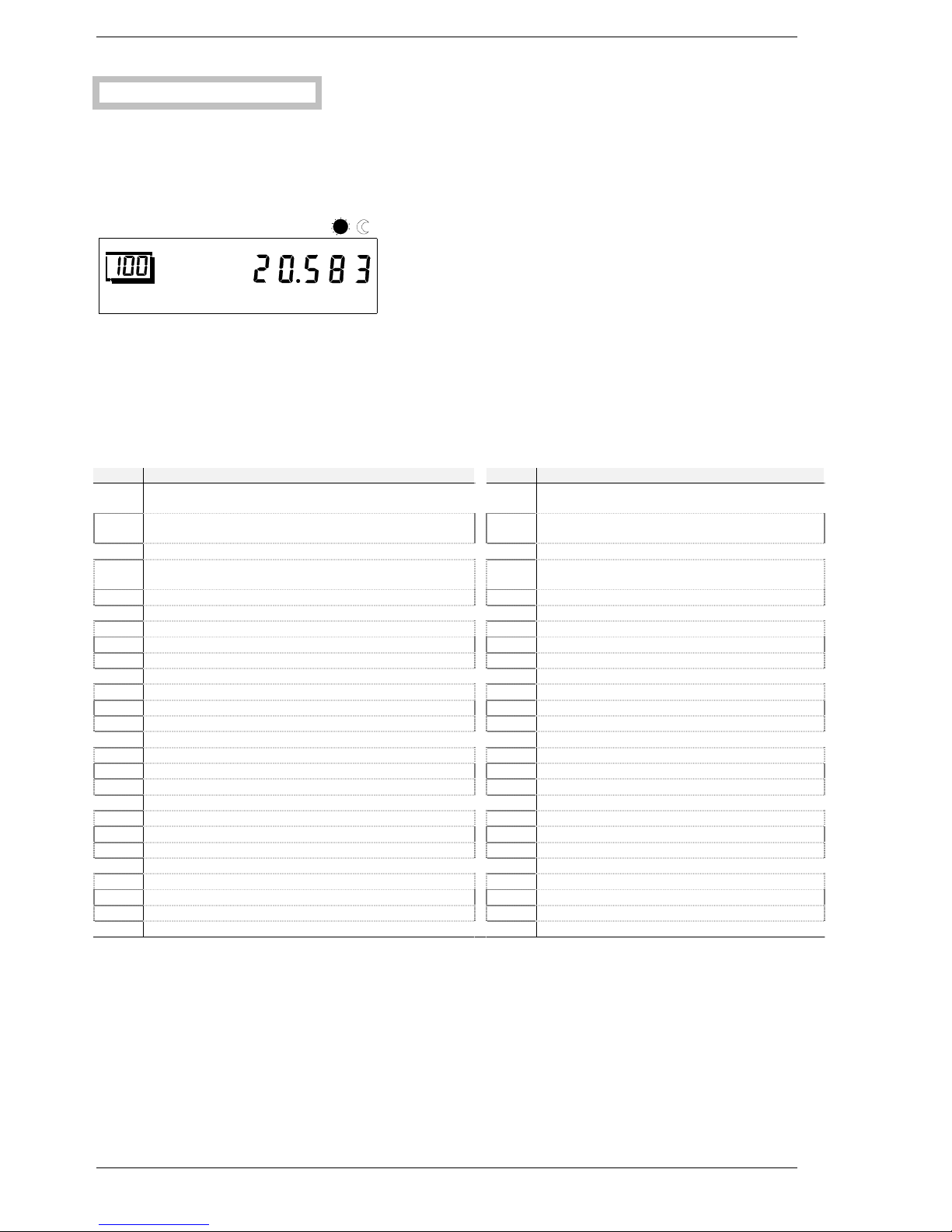
Selection
Selecting the plant type:
Select the required type of plant (basic diagram number) on operating line 100 (refer to page 8). The selection activates all
functions that are required for the specific plant and shows the operating lines needed.
In addition, operating parameters 120 through 173 will be set to their default values required for the basic plant.
During the setting procedure, the basic diagram number on the display flashes. The required number must be confirmed by
pressing the + / - buttons twice for 3 seconds. Then, the basic diagram number will stop flashing.
Example:
2392a04
04
8 12162024
123
4567
89
10
Plant type
The basic plant diagram for the required type of plant and additional setting information will be provided by your local
Siemens Building Technologies / HVAC Products sales office.
Designations of relays and sensors
The relay designations used in the supplied basic diagram have the following meaning:
Relays Function (use) Relays Function (use)
K1 Heat pump stage 1 Y7 Maintained boiler return temperature, oil / gas
OPEN
K2 Heat pump stage 2 Y8 Maintained boiler return temperature, oil / gas
CLOSED
K3 Release of external wood-fired boiler Y9 Maintained boiler return temperature, wood OPEN
K4 Oil- / gas-fired boiler, stage 1 Y10 Maintained boiler return temperature, wood
CLOSED
K5 Oil- / gas-fired boiler, stage 2 Y14 Diverting valve partial storage tank charging
K6 Electric immersion heater for d.h.w. Y¯14 Inverted Y14 signal
K8 Solar collector pump or diverting valve heat exchanger 2 Y15 Diverting valve for return
K¯8 Inverted K8 signal Y¯15 Inverted Y15 signal
K9 Solar bypass valve or heat exchanger pump Q1 Boiler pump of oil- / gas-fired boiler
K¯9 Inverted K9 signal Q2 Heating circuit pump
K10 Alarm output Q3 D.h.w. charging pump
K11 Overtemperature protection Q¯3 Inverted Q3 signal
K¯11 Inverted K11 signal Q4 D.h.w. circulating pump
K12 Solar collector pump or diverting valve heat exchanger 1 Q5 Solar collector pump 1
K13 Output K13 for free time switch program Q9 Heat pump circulator
K14 Release of external oil- / gas-fired boiler Q10 Pump of wood-fired boiler
K15 Release of external heat pump Q11 Storage tank heat transfer pump
K16 Electric immersion heater for buffer storage tank Q12 Oil / gas bypass pump
K17 Flue gas temperature sensor function Q13 D.h.w. storage tank heat transfer pump
K18 Output for solar swimming pool heating Q14 System pump
K¯18 Inverted K18 signal Q15 Pump H1
Y1 Heating circuit mixing valve OPEN Q16 Solar collector pump 2
Y2 Heating circuit mixing valve CLOSED Q17 Additional pump Q17 for heat pump stage 2
Y3 Diverting valve d.h.w. E1 Mains input
Y4 Heat generation lock L Live conductor (mains connection)
Y¯4 Inverted Y4 signal N Neutral conductor (mains connection)
Page 5
Siemens Building Technologies / HVAC Products 74 319 0312 0 a 19.08.2002 5/28
Sensor designations
The sensor designations used in the supplied basic diagram have the following meaning:
Sensor Function (use) Types of
sensors
Sensor Function (use) Types of sen-
sors
B1 Heating circuit flow sensor LG-Ni 1000 B7 Return sensor oil / gas LG-Ni 1000
B2 Sensor of oil- / gas-fired boiler LG-Ni 1000 B71 Return sensor heat pump LG-Ni 1000
B21 Heat pump flow sensor LG-Ni 1000 B72 Return sensor wood LG-Ni 1000
B22 Sensor of wood-fired boiler LG-Ni 1000 B73 Return sensor heating circuit LG-Ni 1000
B3 D.h.w. sensor 1 LG-Ni 1000 B8 Flue gas sensor Pt 1000
B31 D.h.w. sensor 2 LG-Ni 1000 B9 Outside sensor LG-Ni 1000
NTC 600
B32 D.h.w. sensor 3 LG-Ni 1000 B10 Common flow sensor LG-Ni 1000
B33 D.h.w. sensor 4 LG-Ni 1000 B13 Sensor for solar swimming pool
heating
LG-Ni 1000
B4 Buffer storage tank sensor 1 LG-Ni 1000 M Ground sensors H1, U1, P1 –
B41 Buffer storage tank sensor 2 LG-Ni 1000 H1 Contact or DC 0…10 V input –
B42 Buffer storage tank sensor 3 LG-Ni 1000 U1 DC 0…10 V output –
B43 Buffer storage tank sensor 4 LG-Ni 1000 P1 PWM output –
B6 Solar collector sensor 1 LG-Ni 1000 /
Pt 1000
A6 PPS data –
B61 Solar collector sensor 2 LG-Ni 1000 /
Pt 1000
MD PPS ground –
B62 Solar collector flow sensor DB LPB data
B63 Solar flow sensor for yield measurement LG-Ni 1000 MB LPB ground
B64 Solar return sensor for yield measure-
ment
LG-Ni 1000 –
Parameter list
Settings to be made on the «Enduser» level
Settings that meet individual enduser needs.
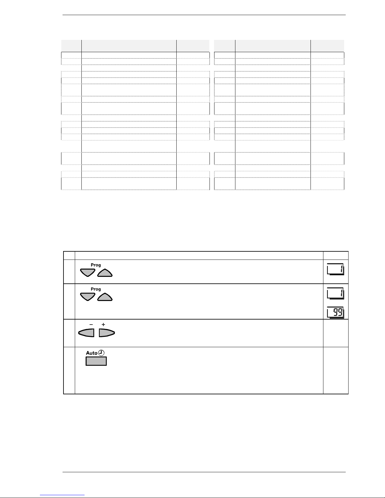
Buttons Explanation Line
1
Press one of the operating line selection buttons.
This will take you directly to programming mode “Enduser“.
2
Press the operating line selection buttons to select the required operating line.
The following parameter list contains all settings that can be made.
• • •
3
Press the + or – button to set the required value.
The setting will be stored as soon as you leave the programming mode or
change to another line.
4
To leave programming mode “Enduser“, press any of the operating mode buttons.
è Note:
If no button is pressed for about 8 minutes, the controller will automatically return to the operating mode selected last.
Continuous
display
Page 6

6/28 19.08.2002 74 319 0312 0 a Siemens Building Technologies / HVAC Products
Overview of the enduser parameters
Line Function Range Unit Resolution Factory
setting
Setting the clock
1 Time of day 00:00...23:59 h / min .... : .... –
2 Weekday 1...7 Day ...... day –
3 Date 01.01...31.12 Day /
month
.... : .... –
4 Year 2001...2094 Year ...... year –
Time switch program for the heating circuit
5 Weekday – preselection heating circuit
1-7 7-day block
1...7 Individual days
1-7 / 1...7 Day ...... day –
6 Switch-on time 1st period heating circuit 00:00...24:00 h / min .... : ....
h / min
06:00
7 Switch-off time 1st period heating circuit 00:00...24:00 h / min .... : ....
h / min
22:00
8 Switch-on time 2nd period heating circuit 00:00...24:00 h / min .... : ....
h / min
- -:- -
9 Switch-off time 2nd period heating circuit 00:00...24:00 h / min .... : ....
h / min
- -:- -
10 Switch-on time 3rd period heating circuit 00:00...24:00 h / min .... : ....
h / min
- -:- -
11 Switch-off time 3rd period heating circuit 00:00...24:00 h / min .... : ....
h / min
- -:- -
Free time switch program
12 Weekday – preselection free time switch program
1-7 7-day lock
1...7 Individual days
1-7 / 1...7 Day ...... day –
13 Switch-on time 1st period free time switch pr. 00:00...24:00 h / min .... : ....
h / min
06:00
14 Switch-off time 1st period free time switch pr. 00:00...24:00 h / min .... : ....
h / min
22:00
15 Switch-on time 2nd period free time switch pr. 00:00...24:00 h / min .... : ....
h / min
- -:- -
16 Switch-off time 2nd period free time switch pr. 00:00...24:00 h / min .... : ....
h / min
- -:- -
17 Switch-on time 3rd period free time switch pr. 00:00...24:00 h / min .... : ....
h / min
- -:- -
18 Switch-off time 3rd period free time switch pr. 00:00...24:00 h / min .... : ....
h / min
- -:- -
Time switch program for d.h.w. heating
19 Weekday – preselection d.h.w.
1-7 7-day block
1...7 Individual days
1-7 / 1...7 Day ...... day –
20 Switch-on time 1st period d.h.w. 00:00...24:00 h / min .... : ....
h / min
06:00
21 Switch-off time 1st period d.h.w. 00:00...24:00 h / min .... : ....
h / min
22:00
22 Switch-on time 2nd period d.h.w. 00:00...24:00 h / min .... : ....
h / min
- -:- -
23 Switch-off time 2nd period d.h.w. 00:00...24:00 h / min .... : ....
h / min
- -:- -
24 Switch-on time 3rd period d.h.w. 00:00...24:00 h / min .... : ....
h / min
- -:- -
25 Switch-off time 3rd period d.h.w. 00:00...24:00 h / min .... : ....
h / min
- -:- -
Page 7

Siemens Building Technologies / HVAC Products 74 319 0312 0 a 19.08.2002 7/28
Line Function Range Unit Resolution Factory
setting
D.h.w. values
26 Nominal setpoint of the d.h.w. temperature (TBWw)
TBWR Line 770
TBWmax Line 750
EXP
TBWR...TBW
max
°C ...... °C 55
Heating circuit values
27 Reduced setpoint of the room temperature (TRRw)
TRF Line 28
TRN Setpoint knob
TRF...TRN °C ...... °C 16
28 Frost protection setpoint of the room temperature
(TRFw)
TRR Line 27
4...TRR °C ...... °C 10
29 Summer / winter changeover temperature 8...30 °C ...... °C 17
30 Slope of the heating curve 1.0...40 – ...... 15
33 Actual value of the room temperature (TRx) 0...50 °C – –
General
34 Actual value of the outside temperature (TAx)
To set the attenuated outside temperature to Tax, press the + / buttons simultaneously for 3 s
-50...+50 °C – –
38 Resetting the enduser parameters
To reset the parameters of the enduser level to their standard
values, press the + / - buttons simultaneously for 3 s
0 / 1 – – 0
39 Resetting the heating circuit and d.h.w. time switch
programs
To reset the time switch programs of the enduser level to their
standard values, press the + / - buttons simultaneously for 3 s
0 / 1 – – 0
Holiday program
40 Preselection of the holiday period 1...8 – ...... 1
41 Beginning of the holiday period
--.-- Inactive
To deactivate the set holiday period, press the + / - buttons simultaneously for 3 s
--.-- /
01.01...31.12
Day /
month
.... . ....
day /
month
--.--
42 End of the holiday period
--.-- Inactive
To deactivate the set holiday period, press the + / - buttons simultaneously for 3 s
--.-- /
01.01...31.12
Day /
month
.... . ....
day /
month
--.--
General / service
50 Indication of error signals
No display = no fault
10 = fault outside sensor
20 = fault boiler sensor oil / gas B2
25 = fault boiler sensor wood B22
26 = fault common flow sensor B10
28 = fault flue gas sensor B8
30 = fault flow sensor heating circuit B1
33 = fault flow sensor heat pump B21
40 = fault return sensor oil / gas B7
43 = fault return sensor wood B72
44 = fault return sensor heat pump B71
47 = fault common return sensor B73
50 = fault storage tank sensor / thermostat B3
52 = fault storage tank sensor / thermostat B31
55 = fault storage tank sensor / thermostat B32
56 = fault storage tank sensor / thermostat B33
61 = fault room unit
70 = fault storage tank sensor B4
71 = fault storage tank sensor B41
72 = fault storage tank sensor B42
73 = fault collector sensor B6
74 = fault collector sensor B61
75 = fault solar flow sensor B62
76 = fault storage tank sensor B43
79 = fault water / brine sensor B11
81 = short-circuit data bus (LPB)
82 = same bus address exists several times
86 = short-circuit PPS
100 = 2 clock time masters on the data bus (LPB)
127 = legionella temperature not reached
130 = maximum flue gas temperature exceeded
Page 8
8/28 19.08.2002 74 319 0312 0 a Siemens Building Technologies / HVAC Products
Line Function Range Unit Resolution Factory
setting
134 = fault heat pump at input H1
135 = water / brine temperature too low
137 = fault heat pump at input E1
138 = fault control sensor heat pump (operating line 420)
145 = wrong PPS unit (BMU / room unit)
146 = configuration error (operating line 202)
147 = external heat source missing (PPS / LPB)
150 = fault BMU
171 = alarm signal at input H1
172 = alarm signal at input E1
211 = fault wood-fired boiler
231-239 = fault sensor input B101 - B109
241 = fault flow sensor yield measurement B63
242 = fault return sensor measurement B64
243 = fault swimming pool sensor B13
Oil- or gas-fired boiler
60 Chimney sweep
0 = OFF
1 = ON
Outside the programming level, the + / - buttons can be used to
activate / deactivate the second burner stage
0 / 1 – – 0
Solar collectors
65 24-hour yield solar energy 0...999.9 kWh – 0
66 Total yield solar energy
To reset the total yield to 0, press the + / - buttons simultaneously
for 3 s
0...9999999.9 kWh – 0
Heat pump
75 Acknowledgement of heat pump error messages
135 and 137
To reset the error messages to 0, press the + / - buttons simultaneously for 3 s
0 / 1 – – 0
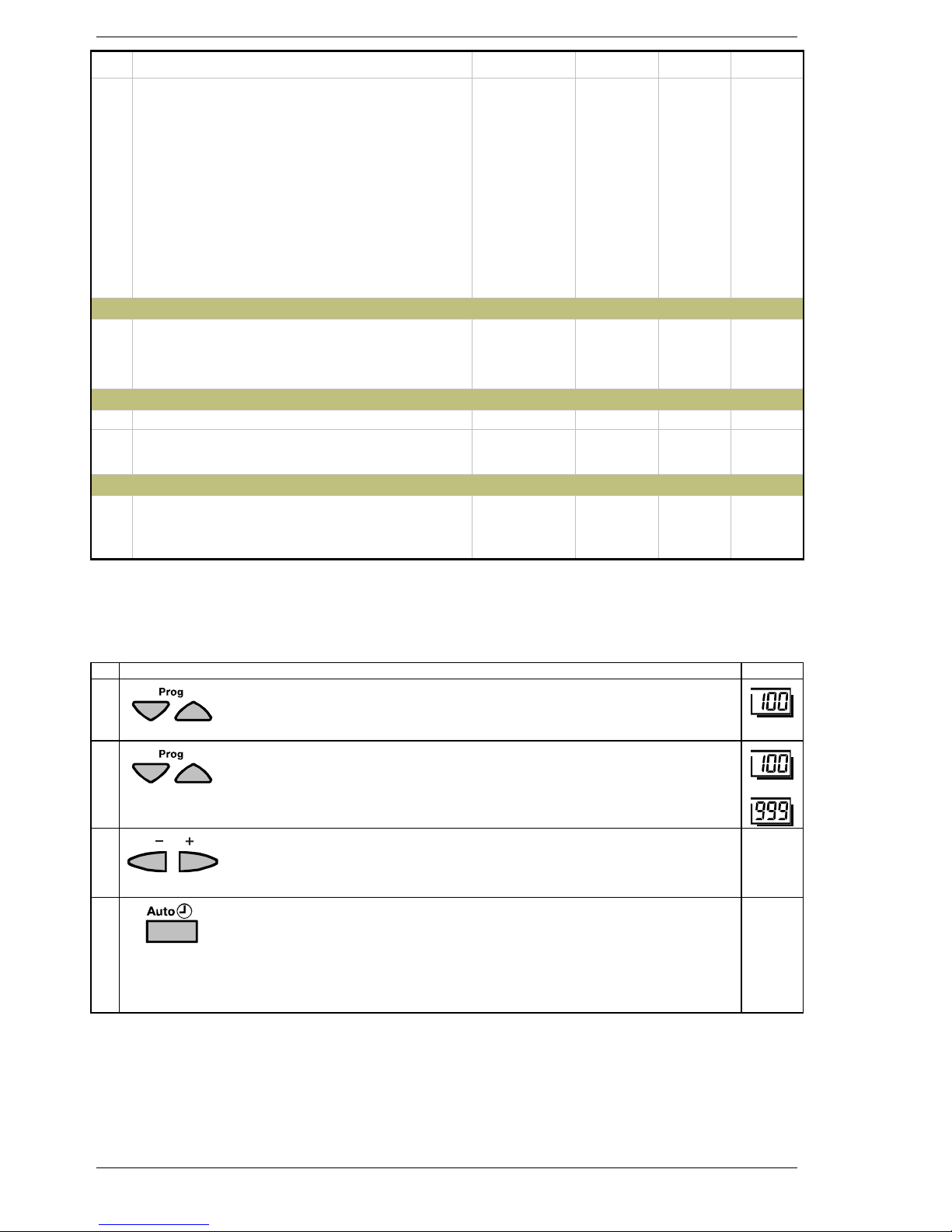
Settings to be made on the «Heating engineer» level
Settings required for the configuration and parameterization by the heating engineer.
Buttons Explanation Line
1
Press both operating line selection buttons for at least 3 seconds.
This will take you to programming level “Enduser”.
2
Press the operating line selection buttons to select the required operating line.
The parameter list on the next pages contains all operating lines on which settings can be made.
• • •
3
Press the + or – button to set the required value.
The setting will be stored as soon as you leave the programming mode or
change to another operating line.
4
To leave programming level “Heating engineer“, press one of the operating
mode buttons.
è Note:
If no button is pressed for about 8 minutes, the controller will automatically return
to the operating mode selected last.
Continuous
display
Page 9

Siemens Building Technologies / HVAC Products 74 319 0312 0 a 19.08.2002 9/28
Overview of the heating engineer parameters
Line Function Range Unit Resolution Factory
setting
General / service
Basic diagrams
100 Selection of the basic diagram
0
No basic diagram selected
1...99.998 Basic diagrams
To adopt the selected diagram number, press the + / - buttons simultaneously for 3 s
0...99.998 – ...... 0
Configuration
Partial diagrams
120 Selection of partial diagram oil- / gas-fired boiler
0
Partial diagram inactive (OeG0)
1...9 Partial diagrams OeG1 through OeG9
0...9 – ...... 0
121 Selection of partial diagram solar collectors
0
Partial diagram inactive (OeG0)
1...16 Partial diagrams Sol1 through Sol16
0...16 – ...... 0
122 Selection of partial diagram wood-fired boiler
0 Partial diagram inactive (Ho0)
1...5 Partial diagrams Ho1 through Ho5
0...5 – ...... 0
123 Selection of partial diagram heat pump
0 Partial diagram inactive (Wp0)
1...5
Partial diagrams Wp1 through Wp5
0...5 – ...... 0
124 Display of partial diagram buffer storage tank
0 Partial diagram inactive (Sp0)
1...3 Partial diagrams Sp1 through Sp3
0...3 – ...... 0
125 Display of partial diagram d.h.w. storage tank
0 Partial diagram inactive (BwSp0)
1...10 Partial diagrams BwSp1 through BwSp10
0...10 – ...... 0
126 Selection of partical diagram combi storage tank
0 Partial diagram inactive (KoSp0)
1...6 Partial diagrams KoSp1 through KoSp6
0...6 – ...... 0
127 Selection of partial diagram heating circuit
0 Partial diagram inactive (Rh0)
1...3 Partial diagrams Rh1 through Rh3
0...3 – ...... 0
Hiding sensors that are not required
130 Source outside sensor
0 Signal via bus (PPS or LPB)
1 Signal via terminal
0 / 1 – ...... 0
131 Reduction 1st d.h.w. sensor B3
0 Without sensor B3
1 With sensor B3
0 / 1 – ...... 0
132 Reduction 2nd d.h.w. sensor B31
0 Without sensor B31
1 With sensor B31
0 / 1 – ...... 0
133 Reduction 2nd buffer storage tank sensor B41
0 Without sensor B41
1 With sensor B41
0 / 1 – ...... 0
135 Reduction wood-fired boiler return sensor B72
0 Without sensor B72
1 With sensor B72
0 / 1 – ...... 0
136 Reduction heat pump flow sensor B21
0 Without sensor B21
1 With sensor B21
0 / 1 – ...... 0
137 Reduction heat pump return sensor B71
0 Without sensor B71
1 With sensor B71
0 / 1 – ...... 0
138 Reduction water / brine sensor B11
0 Without sensor B11
1 With sensor B11
0 / 1 – ...... 0
Page 10

10/28 19.08.2002 74 319 0312 0 a Siemens Building Technologies / HVAC Products
Line Function Range Unit Resolution Factory
setting
Auxiliary functions
140 Return diversion Y15 (ZuFu1)
- - - None
101..110 Relay Y15 at relay terminal Q101...110
101...110 – ...... - - -
141 Return diversion valve inverted Y¯15 (ZuFu1)
- - - None
101..110 Relay Y15 at relay terminal Q101...110
101...110 – ...... - - -
142 Return diversion sensor B73 (ZuFu1)
--- None
101..109 Sensor at sensor terminal B101...B109
101...109 – ...... - - -
143 Partial storage tank charging Y14 (ZuFu2)
- - - None
101..110 Relay Y14 at relay terminal Q101...110
101...110 – ...... - - -
144 Partial storage tank charging valve inverted Y¯14
(ZuFu2)
- - - None
101..110 Relay Y
¯
14 at relay terminal Q101...110
101...110 – ...... - - -
145 Partial storage tank charging sensor B43 (ZuFu2)
- - - None
101..109 Sensor B43 at sensor terminal B101...109
101...109 – ...... - - -
146 Storage tank heat transfer pump Q11 (ZuFu3)
- - - None
101..110 Relay Q11 at relay terminal Q101...110
101...110 – ...... - - -
147 D.h.w. circulating pump Q4 (ZuFu4)
- - - None
101..110 Relay Q4 at relay terminal Q101...110
101...110 – ...... - - -
148 Additional pumpe Q17 for heat pump stage 2
(ZuFu5)
- - - None
101..110 Relay Q17 at relay terminal Q101...110
101...110 – ...... - - -
149 System pump Q14 (ZuFu6)
- - - None
101..110 Relay Q14 at relay terminal Q101...110
101...110 – ...... - - -
150 Pump H1 Q15 (ZuFu7)
- - - None
101..110 Relay Q15 at relay terminal Q101...110
101...110 – ...... - - -
151 Alarm output K10 (ZuFu8)
- - - None
101..110 Relay K10 at relay terminal Q101...110
101...110 – ...... - - -
152 Output overtemperature protection K11 (ZuFu9)
- - - None
101..110 Relay K11 at relay terminal Q101...110
101...110 – ...... - - -
153 Output overtemperature protection inverted K¯11
(ZuFu9)
- - - None
101..110 Relay K
¯
11 at relay terminal Q101...110
101...110 – ...... - - -
154 Relay for flue gas temperature function K17 (ZuFu10)
- - - None
101..110 Relay K17 at relay terminal Q101...110
101...110 – ...... - - -
155 Flue gas sensor B8 (ZuFu10)
- - - None
101..109 Sensor B8 at sensor terminal B101...109
101...109 – ...... - - -
156 3rd buffer storage tank sensor B42 (ZuFu11)
- - - None
101..109 Sensor B42 at sensor terminal B101...109
101...109 – ...... - - -
157 Common flow sensor B10 (ZuFu12)
- - - None
101..109 Sensor B10 at sensor terminal B101...109
101...109 – ...... - - -
158 Solar flow sensor B62 (ZuFu13)
- - - None
101..109 Sensor B62 at sensor terminal B101...109
101...109 – ...... - - -
159 Solar flow sensor B63 for yield measurement (ZuFu14)
- - - None
101..109 Sensor B63 at sensor terminal B101...109
101...109 – ...... - - -
Page 11

Siemens Building Technologies / HVAC Products 74 319 0312 0 a 19.08.2002 11/28
Line Function Range Unit Resolution Factory
setting
160 Solar return sensor B64 for yield measurement
(ZuFu14)
- - - None
101..109 Sensor B64 at sensor terminal B101...109
101...109 – ...... - - -
161 Solar heat exchanger diverting valve inverted K¯8
(ZuFu15)
- - - None
101..110 Relay K
¯
8 at relay terminal Q101...110
101...110 – ...... - - -
162 Solar diverting valve inverted K¯9 (ZuFu16)
- - - None
101..110 Relay K
¯
9 at relay terminal Q101...110
101...110 – ...... - - -
169 Output K13 for free time switch program (ZuFu23)
- - - None
101..110 Relay K13 to relay terminal Q101...110
101...110 – ...... - - -
170 Electric immersion heater buffer storage tank K16
(ZuFu24)
- - - None
101..110 Relay K16 at relay terminal Q101...110
101...110 – ...... - - -
171 Electric immersion heater d.h.w. storage tank K6
(ZuFu25)
- - - None
101..110 Relay K6 at relay terminal Q101...110
101...110 – ...... - - -
172 D.h.w. diverting valve inverted Q¯3 (ZuFu26)
- - - None
101..110 Valve / pump Q
¯
3 at relay terminal Q101...110
101...110 – ...... - - -
173 Heat generation lock Y4 (ZuFu27)
- - - None
101..110 Relay Y4 to relay terminal Q101...110
101...110 – ...... - - -
174 Heat generation lock inverted Y¯4 (ZuFu27)
- - - None
101..110 Relay Y
¯
4 at relay terminal Q101...110
101...110 – ...... - - -
175 Solar swimming pool heating K18 (ZuFu28)
- - - None
101..110 Relay K18 at relay terminal Q101...110
101...110 – ...... - - -
176 Solar swimming pool heating inverted K¯18 (ZuFu28)
- - - None
101..110 Relay K
¯
18 at relay terminal Q101...110
101...110 – ...... - - -
177 Solar swimming pool heating sensor B13 (ZuFu28)
- - - None
101..109 Sensor B13 at sensor terminal B101...109
101...109 – ...... - - -
Miscellaneous
193 D.h.w. heating with charging pump or diverting valve
(Q3)
0 Charging pump
1 Diverting valve
0 / 1 – ...... - - -
194 Setpoint and time switch program for d.h.w. heating
with BMU
0 No
1Yes
0 / 1 – ...... 0
195 Function of system pump Q14
1 For heating circuit only
2 For heating circuit and d.h.w.
3 With external heat demand
1...3 – ...... 1
General
Diagnosis configuration
200 Display of relay terminal assignment
Query with the + / - buttons
101...110 – – –
201 Display of sensor terminal assignment
Query with the + / - buttons
101...109 – – –
Page 12

12/28 19.08.2002 74 319 0312 0 a Siemens Building Technologies / HVAC Products
Line Function Range Unit Resolution Factory
setting
202 Display of configuration errors
No display = no error
1-10 = terminals Q101 - Q110 used beyond capacity
11-19 = terminals B101 - B109 used beyond capacity
24 = B73, Y15 or Y¯15 missing
26 = B43, Y14 or Y¯14 missing
33 = B62 incompatible with partial diagram "Solar"
34 = d.h.w. heating BMU incompatible with partial diagram “D.h.w. /
combi storage tank"
38 = external heat source incompatible with partial diagram "Oil / gas"
39 = inadmissible reduction B72
40 = B13 or K18 / K¯18 missing
41 = B8 missing for function with K17
42 = Q17 incompatible with partial diagram "Heat pump"
43 = Q¯3 incompatible with partial diagram "D.h.w. / combi storage
tank"
45 = K¯9 incompatible with partial diagram "Solar"
51 = inadmissible reduction of B21 and B71
54 = d.h.w. heating BMU incompatible with partial diagram "Oil / gas"
55 = inadmissible reduction of B3 without d.h.w. heating BMU
1...99 – – –
203 Display of plant diagram identification number part 1 0...99‘999‘999 – – –
204 Display of plant diagram identification number part 2 0...99‘999‘999 – – –
205 Display of plant diagram identification number part 3 0...99‘999‘999 – – –
206 Display of plant diagram identification number part 4 0...99‘999‘999 – – –
Terminal test
210 Output test (relay test)
--- Control mode according to the operating state
0 All outputs deactivated
1 Q101 ON
2 Q102 ON
3 Q103 ON
4 Q104 ON
5 Q105 ON
6 Q106 ON
7 Q107 ON
8 Q108 ON
9 Q109 ON
10 Q110 ON
0...10 – – –
211 Input test (sensor test)
1 Sensor at B101
2 Sensor at B102
3 Sensor at B103
4 Sensor at B104
5 Sensor at B105
6 Sensor at B106
7 Sensor at B107
8 Sensor at B108
9 Sensor at B109
10 Room sensor (PPS room unit)
11 Input H1 (ontact or DC 0…10 V)
12 Input E1 (AC 230 V)
1...12 – – –
212 Display of PPS communication
Query with the + / - buttons
- - - No communication
1...12 PPS device address
0...255 Identification code
--- / 1..12 /
0..255
–– –
Setpoint / actual value of common flow
220 Display of the common flow temperature setpoint
--- No value available
0.0...140.0 °C – –
221 Actual value of the common flow temperature
--- No value available
0...140 °C – –
Flue gas temperature
222 Actual value of the flue gas temperature B8
--- No value available
–50...350 °C – –
223 Maximum value of the flue gas temperature display B8
--- No value available
To reset the maximum value to the actual value, press the + / - buttons simultaneously for 3 s
–50...350 °C – 0
Page 13

Siemens Building Technologies / HVAC Products 74 319 0312 0 a 19.08.2002 13/28
Line Function Range Unit Resolution Factory
setting
224 Maximum limitation of the flue gas temperature
--.- Function deactivated
--.- / 0...350 °C ...... °C --.-
225 Switch-on temperature flue gas sensor function
(ZuFu10)
0...350 °C ...... °C 60
226 Switch-off temperature flue gas sensor function
(ZuFu10)
0...350 °C ...... °C 40
Oil- / gas-fired boiler
Setpoints / actual values
250 Display of the boiler temperature setpoint (TKw)
(internal or external PPS-BMU)
--- No values available
0...140 °C – –
251 Actual value of the boiler temperature (TKx)
B2 or external PPS-BMU
--- No values available
–50...350 °C – –
252 Setpoint minimum limitation of the return temperature
Line 280
EXP
...95
°C ...... 8
253 Actual value of the return temperatur B7
--- No value present
–50...350 °C – –
Burner hours run counter / start counter
256 Burner operating hours stage 1 or PPS-BMU
Output K4 or PPS
To make a reset to 0, press the - / + buttons simultaneously for 3 s
0...999‘999 h – 0
257 Burner operating hours stage 2
Output K5
To make a reset to 0, press the - / + buttons simultaneously for 3 s
0...999‘999 h – 0
258 Number of burner starts stage 1
Output K4
To make a reset to 0, press the - / + buttons simultaneously for 3 s
0...999‘999 – – 0
259 Number of burner starts stage 2
Output K5
To make a reset to 0, press the - / + buttons simultaneously for 3 s
0...999‘999 – – 0
Functions
270 Minimum limitation of the boiler temperature (TKmin) 250
EXP
...
251
EXP
(max. 95°C)
°C ......°C 40
271 Frost protection for the plant with the boiler pump
0 General frost protection for the plant does not act on this pump
1 General frost protection for the plant acts on this pump
0 / 1 – ...... 1
Diagnosis
295 Display of BMU error code 0...255 – – –
296 Function test oil- / gas-fired boiler
--- No test
0 Everything OFF
1 Boiler pump ON (Q1)
2 In addition, burner stage 1 ON (Q1+K4)
3 In addition, burner stage 2 ON (Q1+K4+K5)
4 Maintained boiler return temperaturre fixed ON
(Q1+K4+K5+Q12/Y7)
5 Maintained boiler return temperature fixed OFF
(Q1+K4+K5+Q12+Y8)
--- / 0...5 – – - - -
Solar collectors
Setpoints / actual values
300 Actual value of collector temperature B6
--- No value available
–50...350 °C – –
301 Actual value of collector temperature B61
--- No value available
–50...350 °C – –
302 Actual value of collector flow temperature B62
--- No value available
–50...350 °C – –
303 Maximum value of collector temperature 1 (B6)
To make a reset to the actual value, press the + / - buttons simultaneously for 3 s
–50...350 °C – 0
304 Maximum value of collector temperature 2 (B61)
To make a reset to the actual value, press the + / - buttons simultaneously for 3 s
–50...350 °C – 0
Page 14

14/28 19.08.2002 74 319 0312 0 a Siemens Building Technologies / HVAC Products
Line Function Range Unit Resolution Factory
setting
Temperature differential collector / heat exchanger
305 Display of the temperature differential collector 1 / heat
exchanger 1
--- No value available
–50...350 K – –
306 Display of the temperature differential collector 1 / heat
exchanger 2
--- No value available
–50...350 K – –
307 Display of temperature differential collector 2 / heat ex-
changer 1
--- No value available
–50...350 K – –
308 Display of temperature differential collector 2 / heat ex-
changer 2
--- No value available
–50...350 K – –
309 Temperature differential collector 1 / swimming pool
--- No value available
–50...350 K – 1
310 Temperature differential collector 2 / swimming pool
--- No value available
–50...350 K – 1
Hours run counter
311 Operating hours collector pump 1 (output Q5)
To make a reset to 0, press the - / + buttons simultaneously for 3 s
0...999‘999 h – 0
312 Operating hours collector pump 2 (output Q16)
To make a reset to 0, press the - / + buttons simultaneously for 3 s
0...999‘999 h – 0
313 Operating hours pump K12
To make a reset to 0, press the - / + buttons simultaneously for 3 s
0...999‘999 h – 0
314 Operating hours diverting valve K8
To make a reset to 0, press the - / + buttons simultaneously for 3 s
0...999‘999 h – 0
315 Operating hours swimming pool heating K188
To make a reset to 0, press the - / + buttons simultaneously for 3 s
0...999‘999 h – 0
Swimming pool heating
317 Setpoint temperature swimming pool 0...line 321 °C ...... °C 25
318 Actual value of swimming pool temperature B13
--- No value available
–50...350 °C – –
319 Temperature differential swimming pool ON Line 320...40 K ...... K 8
320 Temperature differential swimming pool OFF 0...line 319 K ...... K 4
321 Maximum swimming pool charging temperature 20...95 °C ...... °C 35
322 Heat exchanger pump operation for swimming pool
1 Alternatively
2 Parallel
1 / 2 – ...... 1
323 Measured value correction swimming pool sensor B13 –10.0...10.0 K ...... K 0.0
Functions
324 Selection of collector sensor B6 / B61
1 LG-Ni 1000
2 Pt 1000
1...2 – ...... 1
325 Measured value correction of collector sensor 1 B6 –10.0...10.0 K ...... K 0.0
326 Measured value correction of collector sensor 2 B61 –10.0...10.0 K ...... K 0.0
327 Measured value correction of collector flow sensor B62 –10.0...10.0 K ...... K 0.0
328 Heat exchanger pump operation partial diagram Sol5
1 Alternative operation
2 Parallel operation
1...2 – ...... 2
329 Temperature differential ON heat exchanger 1 Line 330...40 °C ...... °C 8
330 Temperature differential OFF heat exchanger 1 0...line 329 °C ...... °C 4
331 Temperature differential ON heat exchanger 2 Line 332...40 °C ...... °C 8
332 Temperature differential OFF heat exchanger 2 0...line 331 °C ...... °C 4
333 Priotity with 2 heat exchangers
1 No priority
2 Relative priority buffer storage tank (het exchanger 1)
3 Absolute priority buffer storage tank (heat exchanger 1)
4 Relative priority d.h.w. storage tank (heat exchanger 2)
5 Absolute priority d.h.w. storage tank (heat exchanger 2)
1...5 – ...... 4
Solar yield / recooling measurement
338 Type of antifreeze agent used
1 None (only water)
2 Ethylenglycol
3 Propylenglycol
4 Mixture of Ethylen- and Propylenglycol
1...4 – ...... 1
Page 15

Siemens Building Technologies / HVAC Products 74 319 0312 0 a 19.08.2002 15/28
Line Function Range Unit Resolution Factory
setting
339 Concentration of antifreeze agent 1...100 % ...... % 30
340 Pulse value flow meter
(supports 1, 2.5, 10, 25, 100 liters / pulse)
1.0 / 2.5 / 10 /
25 / 100
– ...... 10.0
341 Volumetric flow solar pump 10...1500 Liters/h ......
Liters/h
200
342 Selection of sensor for solar yield measurement
(B63 and B64)
1 LG-Ni 1000
2 Pt 1000
1 / 2 – ...... 2
343 Actual value of solar flow temperature B63
--- No value available
–50...350 °C – –
344 Actual value of solar return temperature B64
--- No value available
–50...350 °C – –
Speed-controlled pump
345 Display of speed of solar pump Q5 / K9 0...100 % – –
346 Minimum speed of the solar pump 0...line 347 % ...... % 40
347 Maximum speed of the solar pump Line 346
...100
% ...... % 100
Diagnosis
349 Functional test solar
--- No test
0 Everything OFF
1 Q5 ON
2 Q5/K12 + Q16 ON
3 Q5/K12 + Q16 + K9 ON
4 Q5/K12 + Q16 + K9 + K8 ON
--- / 0...4 – – - - -
Wood-fired boiler
Setpoints / actual values
350 Display of the boiler temperature setpoint 0...140 °C – –
351 Display of actual value of boiler temperature B22
--- No value available
–50...350 °C – –
352 Display of the boiler return temperature setpoint 0...140 °C – –
353 Display of actual value of return temperature B72
--- No value available
–50...350 °C – –
Hours run counter
354 Operating hours pump of wood-fired boiler
(output Q10)
To make a reset to 0, press the - / + buttons simultaneously for 3 s
0...999‘999 h – 0
355 Operating hours wood-fired boiler (output K3)
To make a reset to 0, press the - / + buttons simultaneously for 3 s
0...999‘999 h – 0
356
Number of releases of wood-fired boiler (output K3)
To make a reset to 0, press the - / + buttons simultaneously for 3 s
0...999‘999 – – 0
Functions
369 Minimum temperature differential of the wood-fired
boiler
0...20 K ...... K 4
370 Minimum temperature of the wood-fired boiler for re-
lease of the pump
20...80 °C ...... °C 60
371 Switching differential for minimum temperature of the
wood-fired boiler for release of the pump
1...30 K ...... K 12
372 Pump overrun time
--- No pump overrun time
--- / 4...120 min ...... min 20
373 Strategy of wood-fired boiler
0 Constant
1 Depending on demand
0 / 1 – ...... 1
376 Wood-fired boiler locks all other heat sources
0 No
1 Yes
0 / 1 – ...... 1
378 Frost protection for the plant with pump of the wood-
fired boiler
0 General frost protection for the plant does not act on this pump
1 General frost protection for the plant acts on this pump
0 / 1 – ...... 1
Page 16

16/28 19.08.2002 74 319 0312 0 a Siemens Building Technologies / HVAC Products
Line Function Range Unit Resolution Factory
setting
Residual heat function
385 Maximum duration of the residual heat function
--- Function deactivated
--- / 5...60 min ...... min - - -
386 Perform residual heat function once / several times
0Once
1 Several times
0 / 1 – ...... 0
387 Residual heat function with buffer stratification protec-
tion
0No
1Yes
0 / 1 – ...... 0
388 Residual heat function directly for the consumers
0No
1Yes
0 / 1 – ...... 0
Speed-controlled pump
390 Display of speed of pump Q10 of the wood-fired boiler 0...100 % – –
391 Minimum speed of pump of the wood-fired boiler 0...line 392 % ...... % 50
392 Maximum speed of pump of the wood-fired boiler Line 91...100 % ...... % 100
Diagnosis
395 Functional test of the wood-fired boiler
--- No test
0 Everything OFF
1 Boiler pump ON (Q10)
2 In addition, burner ON (Q10 + K3)
3 In addition, maintained boiler return temperature ON (Q10 + K3
+ Y10)
4 In addition, maintained boiler return temperature OFF (Q10 +
K3 + Y9)
--- / 0...4 – – - - -
Heat pump
Setpoints / actual values
400 Display of setpoint of the heat pump flow temperature 0...140 °C – –
401 Actual value of heat pump flow temperature B21
--- No value available
–50...350 °C – –
402 Display of setpoint of the heat pump return temperature 0...140 °C – –
403 Actual value of heat pump return temperature B71
--- No value available
–50...350 °C – –
404 Actual value of water / brine flow temperature B11
--- No value available
–50...350 °C – –
Hours run counter
410 Operating hours stage 1 (output K1)
To make a reset to 0, press the - / + buttons simultaneously for 3 s
0...999‘999 h – 0
411 Operating hours stage 2 (output K2)
To make a reset to 0, press the - / + buttons simultaneously for 3 s
0...999‘999 h – 0
412 Number of starts of stage 1 (output K1)
To make a reset to 0, press the - / + buttons simultaneously for 3 s
0...999‘999 – – 0
413 Number of starts of stage 2 (output K2)
To make a reset to 0, press the - / + buttons simultaneously for 3 s
0...999‘999 – – 0
Functions
420 Control sensor for the heat pump:
1 Flow sensor (B21)
2 Return sensor (B71)
3 Common flow sensor (B10)
4 Mean value ((B21+B71)/2)
5 ON with flow sensor (B21) / OFF with return sensor (B71)
6 ON with flow sensor (B21) / OFF with buffer sensor
(B42 / B41 / B4)
7 ON with common flow sensor (B10) / OFF with buffer sensor
(B42 / B41 / B4)
8 ON with return sensor (B71) / OFF with buffer sensor
(B42 / B41 / B4)
9 On with buffer sensor (B4)
OFF with return sensor (B71)
1...9 – ...... 2
421 Heat pump switching differential ON (SDWp) 1...20 K ...... K 2
422 Heat pump switching differential OFF (SDWp) 1...20 K ...... K 2
423 Flow / return temperature differential at –10 °C 1...30 K ...... K 8
424 Compensation of mixing valve boost
--- Function deactivated
--- / 0...50 K ...... K - - -
426 Frost protection for the heat pump circulator
0 Frost protection does not act on this circulator
1 Frost protection acts on this circulator
0 / 1 – ...... 1
Page 17

Siemens Building Technologies / HVAC Products 74 319 0312 0 a 19.08.2002 17/28
Line Function Range Unit Resolution Factory
setting
427 Additional pump kick for water / brine pump
0No
1Yes
0 / 1 – ...... 0
428 Control of the heat pump circulator 0 / 1 – ...... 1
Diagnosis
445 Functional test of the heat pump
--- No test
0 Everything OFF
1 Q8 ON (solar pump),
2 Q8+Q9 ON (plus heat pump circulator)
3 Q8+Q9+K1 ON (plus 1
st
stage),
4 Q8+Q9+K1+K2 ON (plus 2
nd
stage)
--- / 0...4 – – ---
Buffer storage tank
Setpoints / actual values
450 Actual value of buffer storage tank temperature B4 at
the top
--- No value available
–50...350 °C – –
451 Actual value of buffer storage tank temperature B41 at
the bottom
--- No value available
–50...350 °C – –
452 Actual mean value of buffer storage tank temperature
B42
--- No value available
–50...350 °C – –
453 Actual value of buffer storage tank temperature B43 for
partial charging
--- No value available
–50...350 °C – –
454 Maximum value of buffer storage temperature B4
To make a reset to the actual value, press the + / - buttons simultaneously for 3 s
–50...350 °C – 0
455 Display of actual value of return temperature B73
--- No value available
–50...350 °C – –
456 Display of setpoint of the buffer storage tank tempera-
ture
To adjust the setpoint of the buffer storage tank temperature to the
current heat demand, press the + / - buttons simultaneously for 3 s
0...140 °C – 0
Functions
470 Recharge control buffer storage tank with the wood-
fired boiler
0 With sensor B4 (switching differential)
1 With sensors B4 / B41 (start / stop)
0 / 1 – ...... 0
471 Minimum buffer storage tank level when charging with
the collector (TPmin)
0...line 472 °C ...... °C 0
472 Maximum buffer storage tank charging temperature Line 471...
line 450
EXP
°C ...... °C 80
473 Automatic heat generation lock
--- OFF
0 With B4
1 With B4 and B41 / B42
--- / 0...1 – ...... 0
474 ∆T between buffer storage tank and heat demand of the
heating circuit (for automatic heat generation lock)
–20...20 K ...... K -2
475 Forced charging of buffer storage tank with heat pump
0 None
1 Slave pointer / B4,
2 Slave pointer / B41 or B42,
3 Max. buffer storage tank charging temperature / B4,
4 Max. buffer storage tank charging temperature / B41 or B42
0...4 – ...... 0
Return diversion (ZuFu 1)
480 Return diversion temperature differential ON Line 481...40 K ...... K 10
481 Return diversion temperature differential OFF 0...Zeile 480 K ...... K 5
482 Operating action of return diversion
1 As return temperature setback
2 As return temperature boost
1...2 – ...... 1
483 Storage tank sensor for return diversion
1 Sensor B4
2 Sensor B41
3 Sensor B42
1...3 – ...... 2
Page 18

18/28 19.08.2002 74 319 0312 0 a Siemens Building Technologies / HVAC Products
Line Function Range Unit Resolution Factory
setting
Electric immersion heater
484 Release outside temperature for electric immersion
heater buffer storage tank
--- Function deactivated
--- / –30...30 °C ...... °C –5
485 Selection of control sensor for electric immersion heater
of the buffer storage tank
0 Common flow sensor B10
1 Buffer storage tank sensor B4
0 / 1 – ...... 1
Overtemperature protection
489 Differential of maximum storage tank temperature
(MSP) and buffer storage tank safety temperature
1...50 K ...... K 5
490 Hysteresis for buffer storage tank cooling function with
priority 1
1...20 °C ...... °C 5
491 Priority buffer storage tank cooling with heat transfer
pump
--- Function deactivated
1 Priority 1
2 Priority 2
--- / 1...2 – ...... - - -
492 Priority buffer storage tank cooling with collector pump
--- Function deactivated
1 Priority 1
2 Priority 2
--- / 1...2 – ...... - - -
493 Priority buffer storage tank cooling with heat source
pump
--- Function deactivated
1 Priority 1
2 Priority 2
--- / 1...2 – ...... - - -
494 Priority buffer storage tank cooling with overtempera-
ture protection output
--- Function deactivated
1 Priority 1
2 Priority 2
--- / 1...2 – ...... - - -
495 Priority buffer storage tank cooling by delivering heat for
space heating
--- Function deactivated
1 Priority 1
2 Priority 2
--- / 1...2 – ...... - - -
Storage tank temperature
Functions
520 D.h.w. heating with electric immersion heater K6
1 Frost protection for the storage tank
2 Only in summer operation
3 Always
1...3 – ...... 2
521 Recharge control d.h.w. storage tank
0 With sensor B3 (switching differential)
1 With sensors B3 and B31 (start / stop)
2 D.h.w. heating like setting 0, legionella function like setting 1
0...2 – ...... 0
522 Minimum d.h.w. storage tank level when charging with
collector (TBmin)
0...line 523 °C ...... °C 0
523 Maximum d.h.w. storage tank charging temperature Line 522...
line 500
EXP
°C ...... °C 80
Heat transfer d.h.w. storage tank
530 Heat transfer with d.h.w. sensor
0 With sensor B3
1 With sensor B31
0 / 1 – ...... 0
531 Automatic heat transfer from the buffer to the d.h.w.
storage tank
--- Function deactivated
1 With Q3
2 With Q11
--- / 1...2 – ...... 1
532 Heat transfer strategy in the summer
0 Only for frost protection
1 According to d.h.w. release
2 Always
0...2 – ...... 2
533 Heat transfer strategy in the winter
0 Only for frost protection
1 According to d.h.w. release
2 Always
0...2 – ...... 2
Page 19

Siemens Building Technologies / HVAC Products 74 319 0312 0 a 19.08.2002 19/28
Line Function Range Unit Resolution Factory
setting
534 Temperature differential ON heat transfer Line 535...40 °C ...... °C 6
535 Temperature differential OFF heat transfer 0...line 534 °C ...... °C 4
Overtemperature protection d.h.w. storage tank
539 Differential of maximum storage tank temperature
(MSB) and d.h.w. storage tank safety temperature
1...50 K ...... K 5
540 Hysteresis of the d.h.w. cooling function with priority 1 1...20 °C ...... °C 5
541 Priority of d.h.w. storage tank cooling with transfer
pump
--- Function deactivated
1 Priority 1
2 Priority 2
--- / 1...2 – ...... - - -
542 Priority of d.h.w. storage tank cooling with collector
pump
--- Function deactivated
1 Priority 1
2 Priority 2
--- / 1...2 – ...... - - -
544 Priority of d.h.w. storage tank cooling with overtem-
perature protection output K11
--- Function deactivated
1 Priority 1
2 Priority 2
--- / 1...2 – ...... - - -
Diagnosis
545 Functional test of d.h.w. storage tank
--- No test
0 Everything off
1 Charging pump ON (Q3)
2 In addition, diverting valve ON (Q3 + Y3)
3 Transfer pump ON (Q11)
--- / 0...3 – ...... - - -
Combi storage tank
570 B4 delivers temperature for functionality B31
0No
1Yes
0 / 1 – ...... 0
Bivalent operation
Heat source sequence
620 Lead heat source
1 Oil- / gas-fired boiler
2 Heat pump
3 Wood-fired boiler
1...3 – ...... –
621 Switch-on delay lag heat source 1...255 min ...... min 10
622 Release limit for lag heat source 0...500 K*min .....K*min 200
623 Reset limit for lag heat source 0...500 K*min .....K*min 50
Release according to the outside temperature
630 Release of oil- / gas-fired boiler below the outside tem-
perature threshold
--- Boiler always released
--- / –30...30 °C ...... °C - - -
631 Release of heat pump above the outside temperature
threshold
--- Heat pump always released
--- / –30...30 °C ...... °C - - -
632 Release of wood-fired boiler below the outside tem-
perature threshold
--- Boiler always released
--- / –30...30 °C ...... °C - - -
D.h.w. heating
640 Heat source strategy for d.h.w. heating
1 D.h.w. according to the current heat source sequence.
2 D.h.w. with lag heat source, lead heat source maintains the
room temperature setpoint during d.h.w. heating.
3 D.h.w. with lag heat source, lead heat source is shut down
during d.h.w. heating.
4 D.h.w. with lag heat source if released, lead heat source
maintains the room temperature setpoint during d.h.w. heating.
5 D.h.w. with lag heat source if released, lead heat source is shut
down during d.h.w. heating.
1...5 – ...... 1
Page 20

20/28 19.08.2002 74 319 0312 0 a Siemens Building Technologies / HVAC Products
Line Function Range Unit Resolution Factory
setting
Heating circuit / space heating
Setpoints / actual values
700 Display of the nominal room temperature setpoint
Nominal setpoint plus readjustment made on the room unit
0.0...35.0 °C – –
701 Display of the room temperature setpoint (TRw) 0.0...35.0 °C – –
702 Display of heatign circuit flow temperature setpoint TVw 0...140 °C – –
703 Display of actual value of heating circuit flow tempera-
ture TVx B1
--- No value available
--- / -50...350 °C – –
704 Attenuated outside temperature (TAged) –50.0...50.0 °C – 0
705 Composite outside temperature (TAgem) –50.0...50.0 °C – –
706 Measured value correction of outside sensor B9 –10.0...10.0 K ...... K 0
Functions
720 Parallel displacement of heating curve -4.5...+4.5 K ...... K 0.0
721 Room influence
0 Inactive
1 Active
0 / 1 – ...... 1
722 Switching differential of the room temperature (SDR)
- - . - Inactive
0.5...4.0 Active
- - . - /
0.5...4.0
K ...... K - - . -
723 Min. limitation of the flow temperature setpoint (TVmin)
Tvmax Line 724
8...TVmax °C ...... °C 8
724 Max. limitation of the flow temperature setpoint (TVmax)
Tvmin Line 723
TVmin...95 °C ...... °C 80
725 Type of building construction
0 Heavy
1 Light
0 / 1 – ...... 1
726 Adaption of the heating curve
0 Inactive
1 Active
0 / 1 – ...... 1
727 Maximum forward shift of optimum start control 00:00...06:00 hh:mm .... : ....
hh:mm
00:00
728 Maximum forward shift of optimum stop control 00:00...06:00 hh:mm .... : ....
hh:mm
00:00
730 Locking signal gain heating circuit 0...200 % ...... % 100
732 Frost protection for the plant with the heating circuit
0 General frost protection for the plant does not act on this pump
1 General frost protection for the plant acts on this pump
0 / 1 – ...... 1
733 Outside temperature for start of the room temperature
setpoint boost
Line 734...10 °C 1 - - -
734 Outside temperature for end of the room temperature
setpoint boost
–30... line 733 °C 1 -10
Floor curing function
738 Floor curing dates
0OFF
1 Functional heating
2 Floor curing heating
3 Functional and floor curing heating
0...3 – ...... 0
739 Floor curing data 0...32 / 0...95 Day /°C––
Speed-controlled pump
740 Display of speed heating circuit pump Q2 0...100 % – –
741 Minimum speed of the heating circuit pump 0...line 742 % ...... % 100
742 Maximum speed of the heating circuit pump Line 741
...100
% ...... % 100
743 Speed reduction heating circuit pump
0 According to the heating circuit operating level
1 According to the characteristic
0 / 1 – ...... 1
Page 21

Siemens Building Technologies / HVAC Products 74 319 0312 0 a 19.08.2002 21/28
Line Function Range Unit Resolution Factory
setting
Diagnosis
745 Functional test of the heating circuit
--- No test
0 Everything OFF
1 Heating circuit pump ON (Q2)
2 In addition, mixing valve CLOSED (Q2 + Y2)
3 In addition, mixing valve OPEN (Q2 + Y1)
--- / 0...3 – – - - -
D.h.w. values
Setpoints / actual values
750 Display of the d.h.w. temperature setpoint (TBWw) 0...140 °C – –
751 Actual value of d.h.w. temperature sensor B3 / BMU
--- No value available
--- / -50...350 °C – –
752 Actual value of d.h.w. temperature sensor B31
--- No value available
--- / -50...350 °C – –
753 Actual value of d.h.w. temperature sensor B32
--- No value available
--- / -50...350 °C – –
754 Actual value of d.h.w. temperature sensor B33
--- No value available
--- / -50...350 °C – –
755 Maximum value of d.h.w. temperature B3
To make a reset to the actual value, press the - / + buttons simultaneously for 3 s
--- No value available
--- / -50...350 °C – –
756 Maximum value of d.h.w. temperature B32
To make a reset to the actual value, press the - / + buttons simultaneously for 3 s
--- No value available
--- / -50...350 °C – –
Functions
770 Reduced setpoint of the d.h.w. temperature (TBWR)
TBWwLine 26
8...TBWw °C ...... °C 40
771 Release of d.h.w. heating
0 24 h / day
1 According to the heating circuit time switch program(s) with
forward shift
2 According to the d.h.w. time switch program (lines 19…25)
0...2 – ...... 1
772 Selection of program for the circulating pump
0 According to the heating circuit time switch program
1 According to the release of d.h.w. heating (line 771)
2 According to a free time switch program
3 According to the d.h.w time switch program
0...3 – ...... 1
773 Assignment of d.h.w. heating
0 For local consumer only
1 For all consumers in the same segment
2 For all consumers in the system
0...2 – ...... 2
774 Number of d.h.w. charging cylces
0 Once per day (forward shift 2.5 h)
1 Several times per day (forward shift 1h)
0 / 1 – ...... 1
775 Type of d.h.w. demand
0 Sensor
1 Control thermostat
0 / 1 – ...... 0
776 Boost of the flow temperature setpoint for d.h.w. 0...30 K ...... K 16
777 D.h.w. priority
0 MC + PC absolute
1 MC + PC shifting
2 None (parallel)
3 MC shifting, PC absolute
0...3 1 ...... 1
778 D.h.w. priority when charging with the buffer storage
tank
0 Absolute priority
1 Shifting priority
2 No priority
0...2 – ...... 1
779 Automatic d.h.w. push
0 No
1 Yes
0 / 1 – ...... 0
780 Limitation of the d.h.w. charging time
--- OFF
--- / 5...250 min ...... min 150
Page 22

22/28 19.08.2002 74 319 0312 0 a Siemens Building Technologies / HVAC Products
Line Function Range Unit Resolution Factory
setting
781 Changeover to d.h.w. charging with electric immersion
heater
--- OFF
--- / 20...80 °C ...... °C - - -
Legionella function
790 Periodicity of the legionella function
--- OFF
1...7 Duration / weekday
--- / 1...7 – ...... 7
791 Legionella function strategy
1 Maximum period
2 Fixed period
3 Fixed weekday
1...3 – ...... 1
792 Setpoint of the legionella function 60...95 °C ...... °C 65
793 Time for the legionella function 00:00...24:00 hh:mm .... : ....
hh:mm
18:00
794 Dwelling time at legionella function setpoint
--- Function deactivated
--- / 10...360 min. ...... min 30
795 Circulating pump operation during the legionella func-
tion
0No
1Yes
0 / 1 – ...... 1
General functions
801 Effect of the green button
1 During d.h.w. heating
2 When space heating is active
3 In both situations
1...3 – ...... 2
803 Frost protection for the plant with the system pump
0 General frost protection for the plant does not act on this pump
1 General frost protection for the plant acts on this pump
0 / 1 – ...... 1
804 Central setpoint compensation
--- Function deactivated
1...100 K ...... K - - -
LPB / system
850 LPB device address
0 Standalone
1 Device number
0 / 1 – ...... 1
851 LPB segment address
0 Heat generation segment
1...14 Consumer segments
0...14 – ...... 0
852 LPB power supply
0 OFF (central bus power supply)
1 AUTOMATIC (controller – bus power supply)
0 / 1 – ...... 1
853 Display LPB power supply ON / OFF – – –
855 Range of action of central changeover
0 In the segment
1 In the system (if segment address = 0)
0 / 1 – ...... 1
856 Automatic summer / winter changeover
0 Effect on local heating circuit only
1 Central changeover of all heating circuits
0 / 1 – ...... 0
857 Central standby switch
0 OFF (inactive)
1 ON (all units on standby)
0 / 1 – ...... 0
860 Ouside temperature source
--.-- No signal
00.01 Segment / device address
--.--/
00.01...14.16
–– –
Clock
865 Clock mode
0 Autonomous clock
1 System time without remote adjustment
2 System time with remote adjustment
3 System clock (master)
0...3 – ...... 3
866 Changeover date winter- / summertime 01.01...31.12 tt.mm .... : ....
dd.mm
25.03
867 Changeover date summer- / wintertime 01.01...31.12 tt.mm .... : ....
dd.mm
25.10
Page 23

Siemens Building Technologies / HVAC Products 74 319 0312 0 a 19.08.2002 23/28
Line Function Range Unit Resolution Factory
setting
Input H1
870 Function selection input H1
1 Changeover of operating mode (HC standby / d.h.w. OFF)
2 Changeover of operating mode (only HC standby)
3 Minimum setpoint of flow temperature
(setting on line 871)
4 Heat generation lock oil / gas or heat pump
5 Heat demand DC 0...10 V
6 Error signal / alarm
7 Green mode
8 Charging priority d.h.w. wood firing
9 Reserved
10 Reserved
11 Heat generation lock heat pump
12 Fault heat pump
13 Fault wood-fired boiler
14 Yield mesurement solar
1...14 – – 1
871 Min. setpoint of flow temperature contact H1 (TVHw)
If activated at input H1 (setting 3)
8...TKmax °C ...... °C 70
872 Max. value of heat demand signal DC 0…10 V (H1)
If activated at input H1 (setitng 5)
5...130 °C ...... °C 100
873 Operating action of the contact connected to H1
0 N.C. contact
1 N.O. contact
0 / 1 – ...... 1
Input E1
877 Display of operating hours input E1
To make a reset to 0, press the - / + buttons simultaneously for 3 s
0...999‘999 h – 0
878 Display of number of starts input E1
To make a reset to 0, press the -/+ buttons simultaneously for 3 s
0...999‘999 – – 0
880 Function selection input E1
1 Hours run and start counter
2 Heat generation lock oil / gas
3 Error / alarm message
4 Reserved
5 Heat generation lock heat pump
6 Operating signal for heat pump, hours run and start counter
7 Release of return temperature control of wood-fired boiler
8 Forced charging of buffer storage tank with heat pump
1...8 – ...... 1
881 Oprating action of voltage signal at input E1
0 0 V switches ON
1 230 V switches OFF
0 / 1 – ...... 1
Output P1 (PWM)
885 Assignment of pump P1
1 Solar pump Q5 / K9
2 Pump Q10 of wood-fired boiler
3 Heating circuit pump Q2
4 Reserved
1...4 – ...... 1
886 PWM signal logic
0 Standard
1 Inverted
0 / 1 – ...... 0
887 Display PWM output P1 0...100 % – –
888 Output test P1
--- No test
0-100 PWM setpoint in %
--- / 0...100 % – - - -
Output Ux (0...10 V)
890 Function selection Ux
1 Solar pump Q5 / K9
2 Pump Q10 of wood-fired boiler
3 Heating circuit pump Q2
4 Reserved
5 Setpoint of heat generation
6 Temperature setpoint heat pump
7 Temperature setpoint oil- / gas-fired boiler
8 Temperature setpoint wood-fired boiler
1...8 – ...... 1
891 Maximum value of heat demand
(when used as the temperature setpoint)
5...130 °C 1 100
892 Voltage signal logic
0 Standard
1 Inverted
0 / 1 – ...... 0
Page 24

24/28 19.08.2002 74 319 0312 0 a Siemens Building Technologies / HVAC Products
Line Function Range Unit Resolution Factory
setting
893 Displaying voltage output Ux 0...100 % – –
894 Output test Ux
--- No test
0-100 Voltage setpoint DC 0…10 V (0...100 %)
--- / 0...100 % – - - -
Reset
899 Resetting the heating engineer parameters to the de-
fault values
To reset the parameters of the heating engineer level to the default
values, press the + / - buttons simultaneously for 3 s
0 / 1 – – 0
Parameter settings on the «Experts» level
Settings and protective functions for the experts.
Buttons Explanation Line
1
Press one of the operating line selection buttons.
This will first take you to programming level “Enduser“.
2
9 s
Press both operating line selection buttons for at least 9 seconds. The heating
engineer level will appear after 3 seconds and then – after another 6 seconds –
the EXP programming level with a special display for entering the code.
3 CODE
Press buttons and to enter the required combination of the access
code.
If the combination of buttons is correct, you reach programming mode “EXP“.
è Wrong code:
If the code has been entered incorrectly, the display will return to “Parameterization
heating engineer”.
4
Press the operating line selection buttons to select the required line.
The following parameter list contains all operating lines on which settings can
be made.
• • •
5
Press the + / - button to set the required value.
The setting will be stored as soon as you leave the programming mode or
change to another operating line.
6
To leave the EXP programming level, press any of the operating mode buttons.
è Note:
If no button is pressed for about 8 minutes, the controller will automatically return to the operating mode selected last.
Continuous
display
Access code
2392Z04c
1
2
3456
7
8910
0
48
12 16
20
24
Whether correct or incorrect, each push of a button represents irrevocably a digit of the code.
As a confirmation, the respective digit changes to 1.
You receive the code from your local Siemens Building Technologies / HVAC Products sales office.
Page 25

Siemens Building Technologies / HVAC Products 74 319 0312 0 a 19.08.2002 25/28
Overview of the EXP parameters
Line Function Range Unit Resolution Factory
setting
General EXP
180 General frost protection
0 Inactive
1 Active
0 / 1 – ...... 1
Oil- / gas-fired boiler EXP
250 Minimum limitation of boiler temperature setpoint EXP
(TKminEXP)
8...95 °C ...... °C 40
251 Max. limitation of the boiler temperature setpoint (TKmax) 8...120 °C ...... °C 80
252 Switching differential of the boiler temperature (SDK) 0...20 K ...... K 8
253 Minimum limitation of the burner running time 0...10 min ...... min 4
254 Release limit of burner stage 2 0...500 K*min ......
K*min
50
255 Reset limit of burner stage 2 0...500 K*min ......
K*min
10
256 Pump overrun time
(after burner OFF)
0...20 min ...... min 5
257 Operating mode of the boiler
0 Continuous operation (without extended burner running time)
1 Automatic operation (without extended burner running time)
2 Automatic operation (with extended burner running time)
0...2 – ...... 1
259 Protective boiler startup
0 None
1 With effect on the consumers and on the boiler pump
2 With effect on the consumers
3 With effect on the boiler pump
0...3 – ...... 1
261 Control of the boiler pump
0 According to heat demand
1 Parallel to burner operation
0 / 1 – ...... 0
Minimum limitation of the return temperature
280 Minimum limitation of boiler return temperature EXP 8...line
252
°C ...... °C 8
281 Maintained boiler return temperature with consumer
influence
0 With no effect on the consumers
1 With effect on the consumers
0 / 1 – ...... 1
283 Switching differential of the bypass pump (SDBP) 0...20 K ...... K 6
284 Control of the bypass pump
0 Parallel to burner operation
1 According to the boiler return temperature
0...2 – ...... 0
285 P-band of minimum limitation of the return temperature
oil / gas (Xp)
1...100 K ...... K 24
286 Integral action time for minimum limitation of the
return temperature oil / gas (Tn)
10...873 s ...... s 90
287 Actuator running time minimum limitation of the return
temperature oil / gas
30...873 s ...... s 120
Solar heating plant EXP
300 Maximum temperature collector 1
--- Overtemperature protection OFF
20...350 °C ...... °C 120
301 Maximum temperature controller 2
--- Overtemperature protection OFF
20...350 °C ...... °C 120
302 Hysteresis of maximum limitation of the collector tem-
perature
1...20 °C ...... °C 5
303 Frost protection temperature collector 1 + 2
--- Frost protection OFF
–20...5 °C ...... °C - - -
304 Maximum storage tank charging time 1...60 min ...... min 20
305 Maximum waiting time 1...40 min ...... min 5
307 Changeover / startup delay bypass valve / charging
pump K9
1...15 min ...... min 3
Page 26

26/28 19.08.2002 74 319 0312 0 a Siemens Building Technologies / HVAC Products
Line Function Range Unit Resolution Factory
setting
Collector pump protection
310 Evaporation temperature of heat conducting medium
--- Function deactivated
--- /
80...350
°C ...... °C ---
311 Switching differential to evaporation temperature of
heat conducting medium
1...50 K ...... K 15
Wood-fired boiler EXP
351 Protective boiler startup
0 No
1 Yes
0 / 1 – ...... 0
Minimum limitation of the return temperature
380 Minimum limitation of the boiler return temperature 8...140 °C ...... °C 60
381 P-band of minimum limitation of the return temperature 1...100 K ...... K 24
382 Integral action time of minimum limitation of the return
temperature
10...873 s ...... s 90
383 Running time of actuator for minimum limitation of the
return temperature
30...873 s ...... s 120
Heat pump EXP
400 Maximum switch-off temperature 20...140 °C ...... °C 55
401 Minimum switch-on temperature
--- Function deactivated
--- / 8...95 °C ...... °C - - -
410 Prerun time heat pump pump and water / brine pump 5...240 s ...... s 15
411 Overrun time heat pump pump and water / brine pump 5...240 s ...... s 15
413 Minimum compressor running time 0...60 min ...... min 15
414 Minimum compressor off time 0...60 min ...... min 15
415 Automatic switch-on attempt after heat pump errors 135
and 137
0No
1Yes
0 / 1 – ...... 1
416 Compensation of surplus heat / heat deficit due to run-
ning time
0 Inactive
1 Active
0 / 1 – ...... 1
Second heat pump stage
420 Locking time heat pump stage 2 1...60 min. ...... min 10
421 Release limit heat pump stage 2 0...500 K*min ......
K*min
50
422 Reset limit heat pump stage 2 0...500 K*min ......
K*min
10
423 Changeover of stage sequence
--- Function deactivated
10...990 Automatic changeover based on hours
--- /
10...990
h ...... h - - -
Water / brine temperature
425 Minimum water / brine temperature
--- Function deactivated
--- / –
20...20
°C ...... °C 3
426 Switchung differential for min. water / brine temperature 1...10 K ...... K 3
Buffer storage tank EXP
450 Buffer storage tank safety temperature 20...95 °C ...... °C 90
D.h.w. storage tank EXP
500 D.h.w. storage tank safety temperature 20...95 °C ...... °C 90
Heating circuit EXP
700 Boost of flow temperature setpoint mixing valve (UEM) 0...50 K ...... K 10
701 Gain factor of room influence (KORR) 0...20 – ...... 4
702 Constant for quick setback (KON)
(without room sensor)
0...20 – ...... 2
703 Boost of the room temperature setpoint
(with boost heating)
0...20 K ...... K 5
705 Control mode of mixing valve
0 2-position
1 3-position
0 / 1 – ...... 1
Page 27

Siemens Building Technologies / HVAC Products 74 319 0312 0 a 19.08.2002 27/28
Line Function Range Unit Resolution Factory
setting
706 Switching differential mixing valve
(for 2-position mixing valves)
0...20 K ...... K 2
707 Overtemperature protection for the pump heating circuit
0 Inactive
1 Active
0 / 1 – ...... 1
708 Heat gains -2...4 K ...... K 0
709 Adaption sensitivity 1 1...15 – ...... 15
710 Adaption sensitivity 2 1...15 – ...... 15
711 P-band heating circuit (Xp) 1...100 K ...... K 24
712 Integral action time heating circuit (Tn) 10...873 s ...... s 90
713 Actuator running time heating circuit 30...873 s ...... s 120
D.h.w. EXP
750 Maximum nominal setpoint of the d.h.w. temperature
(TBWmax)
8...80 °C ...... °C 60
751 Switching differential of the d.h.w. temperature (SDBW) 0...20 K ...... K 5
752 D.h.w. discharge protection when charging with the
wood-fired boiler
1 Supervision of sensor of the wood-fired boiler
2 Supervision of sensor of the wood-fired boiler and buffer
storage tank
1 / 2 – ...... 1
753 D.h.w. discharge protection when charging with the oil- /
gas-fired boiler
0 Inactive
1 Supervision of sensor of the oil- / gas-fired boiler
2 Supervision of sensor of the oil- / gas-fired boiler and buffer
storage tank
0...2 – ...... 1
General / service EXP
800 Software version 00.0...99.9 – – –
801 Device operating hours 0...999‘999h––
802 Resetting the OEM parameters
To reset the parameters of the OEM level to their default values,
press the + / - buttons simultaneously for 3 s
0 / 1 – – 0
803 Display version table with basic diagrams 0...32‘767 – – –
Dimensions
19
26 26 26 26
15
96
144
106,8
12
60,4
14
56
112
4,5
138
+1
0
92
+0.8
0
2474M01
9
3
max. 3
Dimensions in mm
Page 28

28/28 19.08.2002 74 319 0312 0 a Siemens Building Technologies / HVAC Products
ã 2002 Siemens Building Technologies Ltd.
 Loading...