

Page 1
74 319 0817 0
G2546
Siemens Building Technologies 74 319 0817 0 a CE1G2546en 28.02.2011 1/12
en
Installation Instructions
Heating controller for
2 heating circuits and d.h.w.
RVP36..
Keep these instructions with the controller!
Installation
Place of installation
• In a dry room (e.g. in the boiler room)
• Installation choices:
– In a compact station
– In a control panel (panel front, inner wall,
or on a top hat rail)
– In a control cabinet
– In the sloping front of a control desk
• Permissible ambient temperature: 0...50 °C
Electrical installation
• Local regulations for electrical installations must be
complied with
• Only qualified personnel may carry out the electrical
installation
• Cable strain relief must be ensured
• Cable glands must be made of plastic
• Cables from the controller to the actuating devices
and pumps carry mains voltage
• Sensor cables must not be run parallel to mains
carrying cables
• A defective or apparently damaged unit must
immediately be disconnected from power
Permissible cable lengths
• For all sensors and thermostats:
Copper cable 0.6 mm dia. max. 20 m
Copper cable 1.0 mm
2
max. 80 m
Copper cable 1,5 mm
2
max. 120 m
• For room units:
Copper cable 0.25 mm
2
max. 25 m
Copper cable from 0.5 mm
2
max. 50 m
• For data buses: As per Siemens specification in
Basic System Data N2030 and
Basic Engineering Data N2032
Mounting and wiring the base
Wall mounting
1. Remove base from controller.
2. Hold base against the wall. Marking TOP must
be at the top!
3. Mark fixing holes on the wall.
4. Drill holes.
5. If required, knock out holes on the base to fit
the cable glands.
6. Screw base to the wall.
7. Wire up the base.
Rail mounting
1. Fit top hat rail.
2. Remove base from controller.
3. If required, knock out holes on the base to fit the
cable glands.
4. Fit base to the rail. Marking TOP must be at the top!
5. If required, secure the base (depending on type
of rail used).
6. Wire up the base.
Flush-panel mounting
• Maximum thickness of front panel: 3 mm.
• Required panel cutout: 138 × 92 mm.
1. Remove base from controller.
2. If required, knock out holes on the base to fit the
cable glands.
3. Insert base in the panel cutout from behind until
stop is reached. Marking TOP must be at the top!
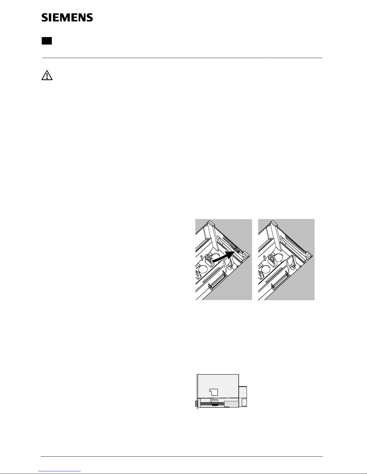
4. Push lateral tongues behind the front panel (see
illustration).
2462Z06
Wrong Correct
Place left and right tongue correctly – must not protrude
inside the cutout!
5. Wire up the base. Cable lengths should be chosen
such that sufficient space is left to open the control
panel door.
Securing the controller to the base
1. Ensure correct position and location of the levers
by turning the fixing screws. Symbol on lateral wall
of the controller:
2540Z04
2. Insert controller in the base until stop is reached.
Marking TOP must be at the top!
3. Tighten fixing screws alternately.
Page 2
Commissioning
Preparatory checks
1. Do NOT turn on power yet.
2. Check wiring to ensure it accords with the plant’s
connection diagram.
3. Check each actuating device to see if …
– it is correctly installed (observe direction of
flow indicated on valve body),
– manual control is disengaged.
4. Exercise caution in connection with floor and
ceiling heating systems!
The limit thermostat must be correctly set. During
the function check, the flow temperature must not
exceed the maximum permissible level (usually
55 °C); if it does, proceed immediately as follows:
– Either close the valve manually, or
– Switch off the pump, or
– Shut the pump isolating valve .
5. Turn on power. The display shows the time of day.
If not, the reason may be one of the following:
– No mains voltage
– Main fuse defective
– Main switch not set to ON
6. Addressing the room units:
– Room unit heating circuit 1 = address 1
(factory setting)
– Room unit heating circuit 2 = address 2
General information about operation
• Setting elements for commissioning:
– Readjustment of room temperature: Via setting knob,
separately for heating circuits 1 and 2!
– Other variables: On the display; each setting is
assigned an operating line. If required, make
separate settings for heating circuits 1 and 2!
• Buttons for selection and adjustment of values:
2/12 28.02.2011 CE1G2546en 74 319 0817 0 a Siemens Building Technologies
Press to select the next lower operating line
Press to select the next higher operating line
Press to decrease the display
ed value
Press to increase the displayed value
• Adopting a setting value:
Setting value is adopted by selecting a new operating
line or by pressing one of the operating mode buttons
• Enter --.- / --:-- / --- (deactivation of function):
Keep or
depressed until the desired display
appears
• Block jump function:
To select an individual operating line quickly,
2 button combinations can be used:
Keep depressed and press
to select the next
higher line block
Keep
depressed and press to select the next
lower line block
• When pressing one of the buttons, the display lighting
is switched on for a certain time
Setting procedure
1. Make the required settings on the "End-user" level
(operating lines 1…50).
2. Configure plant type on operating line 51.
3. Enter the relevant settings on the parameter list
below. All functions and operating lines required for
the configured plant type are activated and adjustable; all operating lines that are not required cannot
be accessed.
4. Make the required settings on the "Heating engineer"
level (operating lines 61…208).
Commissioning and function check
• Operating lines especially for the function check:
161 = simulation of outside temperature
162 = relay test
163 = sensor test
164 = display of setpoint
• If Er (error) appears on the display: Query operating
line 50 to pinpoint the fault
• If no operating line is selected for 30 minutes, or if
one of the operating mode buttons is pressed, the
controller switches to the "non-operated" state
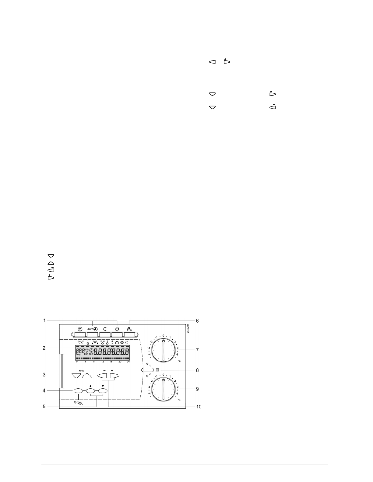
Setting elements
1 Buttons for selectiong the operating mode
2 Display (LCD)
3 Buttons for selecting the operating lines
4 Button for manual control ON / OFF
5 Buttons for valve OPEN / CLOSE when manual
control ON
6 Button for d.h.w. heating ON / OFF
7 Setting knob for readjusting the room temperature
of heating circuit 1
8 Button for switching between the heating circuits
9 Setting knob for readjusting the room temperature
of heating circuit 2
10 Buttons for adjusting values
Page 3
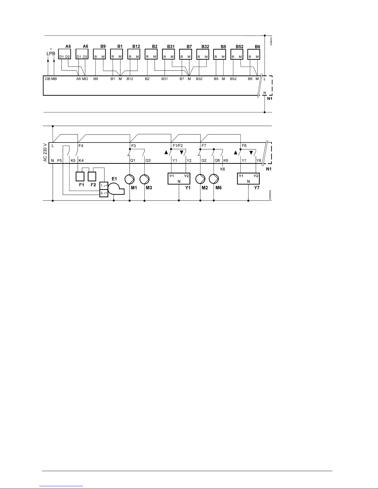
Connection diagrams
Low-voltage side
* LPB only RVP360
Mains voltage side
A6 Room unit F1 Thermal reset limit thermostat
B1 Flow sensor heating circuit 1 F2 Safety limit thermostat
B12 Flow sensor heating circuit 2 K6 Multifunctional output
B2 Boiler sensor LPB Data bus (only RVP360)
B31 D.h.w. storage tank sensor / thermostat M1 Circulating pump
B32 D.h.w. storage tank sensor / thermostat M2 Heating circuit pump heating circuit 1
B5 Room sensor heating circuit 1 M3 Storage tank charging pump
B52 Room sensor heating circuit 2 M6 Heating circuit pump heating circuit 2
B6 Collector sensor N1 Controller RVP36..
B7 Return sensor Y1 Actuator heating circuit 1
B9 Outside sensor Y7 Actuator heating circuit 2
E1 2-stage burner
Siemens Building Technologies 74 319 0817 0 a CE1G2546en 28.02.2011 3/12
Page 4

"End-user" level
To activate the "End-user" level, press or .
Note: The settings made on the controller should be entered on the following parameter list and the Installation
Instructions should be kept with the controller or in a suitable place.
Operating lines highlighted in grey require settings for heating circuit 1 (HC 1) and heating circuit 2
(HC 2)!
Line
Function, display Factory setting
(range)
HC 1
HC 2
Explanations, notes and tips
1 Room temp. setpoint for 20.0 °C .................°C
4/12 28.02.2011 CE1G2546en 74 319 0817 0 a Siemens Building Technologies
NORMAL heating (0.0…35.0) .................°C
2 Room temp. setpoint for 14.0 °C .................°C
REDUCED heating (0.0…35.0) .................°C
3 Room temp. setpoint for 10.0 °C .................°C
holiday / protection mode (0.0…35.0) .................°C
4 Weekday, for entering the Current weekday 1 = Monday
heating program (1…7 / 1-7) 2 = Tuesday, etc.
1-7 = entire week
5 1st heating phase,
start of NORMAL heating
6:00
(--:-- / 00:00…24:00)
........................
........................
6 1st heating phase,
end of NORMAL heating
22:00
(--:-- / 00:00…24:00)
........................
........................
7 2nd heating phase,
start of NORMAL heating
--:--
(--:-- / 00:00…24:00)
........................
........................
8 2nd heating phase,
end of NORMAL heating
--:--
(--:-- / 00:00…24:00)
........................
........................
9 3rd heating phase,
start of NORMAL heating
--:--
(--:-- / 00:00…24:00)
........................
........................
10 3rd heating phase,
end of NORMAL heating
--:--
(--:-- / 00:00…24:00)
Scheduler program for heating circuit
--:-- = phase deactivated
........................
........................
12 Date of first day of holiday --.--
(01.01…31.12)
........................
........................
13 Date of last day of holiday --.--
(01.01…31.12)
dd.mm
--.-- = holiday period deactivated
........................
........................
14 Heating curve, flow tempera- 30 °C .................°C
ture setpoint at an outside
temperature of 15 °C
(20…70) .................°C
15 Heating curve, flow tempera- 60 °C .................°C
ture setpoint at an outside
temperature of -5 °C
(20…120) .................°C
26 Setpoint for NORMAL
d.h.w. temperature
55 °C
(20…100)
.................°C
27 Display of current
d.h.w. temperature
Display function
28 Setpoint for REDUCED
d.h.w. temperature
40 °C
(8…80)
.................°C
31 Weekday, for entering
scheduler program 2
Current weekday
(1…7 / 1-7)
1 = Monday
2 = Tuesday, etc.
1-7 = entire week
32 Start of 1st ON phase 5:00
(--:-- / 00:00…24:00)
........................
33 End of 1st ON phase 22:00
(--:-- / 00:00…24:00)
........................
34 Start of 2nd ON phase --:--
(--:-- / 00:00…24:00)
........................
35 End of 2nd ON phase --:--
(--:-- / 00:00…24:00)
........................
36 Start of 3rd ON phase --:--
(--:-- / 00:00…24:00)
........................
37 End of 3rd ON phase --:--
(--:-- / 00:00…24:00)
........................
Scheduler program 2
--:-- = phase deactivated
Page 5

38 Time of day hh:mm
(00:00…23:59)
........................
39 Weekday Display function 1 = Monday
2 = Tuesday, etc.
40 Date dd.mm
(01.01…31.12)
........................
41 Year yyyy
(2009…2099)
........................
Display function
Example:
Interconnected system
Siemens Building Technologies 74 319 0817 0 a CE1G2546en 28.02.2011 5/12
20 = error code
06 = segment number (LPB)
02 = device number (LPB)
50 Faults
10 = fault outside sensor B9
20 = fault boiler sensor B2
30 = fault flow sensor B1, heating circuit 1
32 = fault flow sensor B12, heating circuit 2
40 = fault primary return sensor B7
50 = fault storage tank sensor B31
52 = fault storage tank sensor B32
60 = fault room sensor B5, heating circuit 1
61 = fault room unit A6, heating circuit 1
62 = device with wrong PPS identification
connected, heating circuit 1
65 = fault room sensor B52, heating circuit 2
66 = fault room unit A6, heating circuit 2
67 = device with wrong PPS identification
connected, heating circuit 2
73 = fault collector sensor B6
81 = short-circuit on data bus (LPB)
82 = 2 devices with the same bus
address (LPB)
86 = short-circuit PPS
100 = 2 clock time masters (LPB)
140 = inadmissible bus address (LPB)
Page 6

"Heating engineer" level
To activate the "Heating engineer" level, press and simultaneously for 3 seconds. This level is used to
configure the plant type and to set the plant-specific variables.
• The "End-user" level also remains activated when on the "Heating engineer" level.
Note: The heating engineer should enter the function of "Scheduler program 2" in the Operating Instructions.
Configuring the plant type:
Select the required plant type on operating line 51 (see the following plant diagrams). This activates all functions
needed for the particular type of plant and the required operating lines appear.
Example:
2477Z02
Display for plant type 5-1
51 Operating line
5 Heating circuit type
1 D.h.w. type
Plant types
For meaning of symbols, refer to "Connection diagrams".
Plant types 4-x
Plant types 5-x
6/12 28.02.2011 CE1G2546en 74 319 0817 0 a Siemens Building Technologies
Page 7

Plant types 6-x
Function block "Plant configuration"
51 Plant type 5-1
(4-0...6-1)
........................
See the plant diagrams above
Function block "Space heating"
61 Heating limit NORMAL 17.0 °C .................°C
--- = function deactivated
Siemens Building Technologies 74 319 0817 0 a CE1G2546en 28.02.2011 7/12
(ECO day) (--- / –5.0…25.0) .................°C
62 Heating limit REDUCED 5.0 °C .................°C
--- = function deactivated
(ECO night) (--- / –5.0…25.0) .................°C
63 Building time constant 20 h
(0…50)
....................h
10 h = light building construction
20 h = medium building construction
50 h = heavy building construction
64 Quick setback 1 0 = without quick setback
........................
(0 / 1) 1 = with quick setback
........................
65 Room temperature source A 0 = no room sensor available
........................
(0…3 / A) 1 = room unit connected to terminal A6
........................
2 = room sensor connected to terminal B5
3 = mean value of both devices connected to
terminals A6 and B5 (heating circuit 1)
and / or A6 and B52 (heating circuit 2)
A = automatic selection
66 Type of optimization 0 0 = optimization with room model
........................
(0 / 1) 1 = optimization with room unit / room sensor
........................
(setting 0 only provides optimum start control)
67 Maximum heating up period 0:00 h .....................h Maximum forward shift for switching on
(0:00...42:00) .....................h before occupancy starts
0:00 = no optimum start control
68 Maximum early shutdown 0:00 h .....................h Maximum forward shift for switching off
(0:00...6:00) .....................h before occupancy ends
0:00 = no optimum stop control
69 Maximum limitation of room --.- °C .................°C --- = limitation deactivated,
temperature (--.- / 0.0…35.0) .................°C function can only be provided with
room unit / room sensor
70 Influence of room 4 Function can only be provided with
........................
temperature (gain factor) (0…20) room unit / room sensor
........................
71 Boost of room temperature 5 °C .................°C
setpoint on boost heating (0…20) .................°C
Page 8

Function block "Pump heating circuit"
75 Overtemperature protection
for the pump heating circuit
1
(0 / 1)
.......................
0 = without overtemperature protection
1 = with overtemperature protection
Note: Can only be set for heating circuit 1
Function block "Actuator heating circuit"
81 Maximum limitation --- °C .................°C --- = function deactivated
8/12 28.02.2011 CE1G2546en 74 319 0817 0 a Siemens Building Technologies
flow temperature (--- / 0…140) .................°C
Caution: This is not a safety function!
82 Minimum limitation --- °C .................°C --- = function deactivated
flow temperature (--- / 0…140) .................°C
Caution: This is not a safety function!
83* Maximum rate of --- K/h ...............K/h
--- = function deactivated
flow temperature increase (--- / 1...600) ...............K/h
84* Setpoint boost mixing valve 10 K ....................K
(0…50) ....................K
85* Actuator running time 120 s
(30…873)
.....................s
.....................s
86* P-band of control 32.0 K
(1.0…100.0)
....................K
....................K
87* Integral action time of control 120 s
(10…873)
Settings only required for 3-postion control
.....................s
.....................s
88* Type of actuator 1 0 = 2-position control
.......................
.......................
(0 / 1) 1 = 3-position control
89* Switching differential 2 K ....................K
Setting only required for 2-postion control
(1…20) ....................K
* Note: Operating lines 83 through 89 with plant type 6-x can only be set for heating circuit 2!
Function block "Boiler"
91 Boiler operating mode 0
(0…2)
.......................
0 = with manual shutdown (button )
1 = with automatic shutdown (OFF when
there is no demand for heat)
2 = without shutdown
92 Maximum limitation boiler
temperature
95 °C
(25…140)
.................°C
Caution: This is not a safety function!
93 Minimum limitation boiler
temperature
10 °C
(5…140)
.................°C
94 Switching differential boiler 6 K
(1…20)
....................K
95 Minimum limitation burner
running time
4 min
(0…10)
..............min
96 Burner stage 2
release integral
50 °Cxmin
(0…500)
.......................
°Cxmin
97 Burner stage 2
reset integral
10 °Cxmin
(0…500)
.......................
°Cxmin
98 Burner stage 2
locking time
20 min
(0…40)
..............min
99 Operating mode pump M1 1
(0 / 1)
........................
0 = without shutdown on protective boiler
startup
1 = with shutdown on protective boiler startup
Function block "Limitation of return temperature"
101 Setpoint return temperature
limitation, constant value
--- °C
(--- / 0…140)
.................°C
--- = function deactivated
Page 9

Siemens Building Technologies 74 319 0817 0 a CE1G2546en 28.02.2011 9/12
Function block "D.h.w."
121 Assignment of d.h.w.
(only RVP360)
0
(0…2)
.......................
D.h.w. heating for
0 = locally
1 = all controllers in the interconnected
system having the same segment
number
2 = all controllers in the interconnected
system
123 Release of d.h.w. heating 2
(0…2)
........................
0 = always (24 h/day)
1 = according to heating program(s),
depending on setting made on
operating line 121
Start of release is shifted forward by
1 hour
2 = according to scheduler program 2
Note: This setting is to be entered in the
Operating Instructions.
Priority of d.h.w. Flow temperature
setpoint according to:
0 = absolute D.h.w.
1 = shifting D.h.w.
2 = shifting Maximum selection
3 = none (parallel) D.h.w.
124 D.h.w. priority 0
(0…4)
........................
4 = none (parallel) Maximum selection
126 D.h.w. storage tank
sensor / thermostat
0
(0…5)
........................
0 = one sensor
1 = two sensors
2 = one thermostat
3 = two thermostats
4 = one sensor with solar d.h.w. heating
5 = two sensors with solar d.h.w. heating
127 Boost d.h.w. charging
temperature
10 K
(0…50)
....................K
128 Switching differential d.h.w. 8 K
(1…20)
....................K
129 Maximum period d.h.w.
charging
60 min
(--- / 5…250)
..............min
--- = no limitation of charging time
130 Setpoint legionella function --- °C
(--- / 20…100)
.................°C
--- = function deactivated
131 Forced charging 0
(0 / 1)
........................
0 = without forced charging
1 = with daily forced charging on first
release
Function block "Multifunctional relay"
141 Function multifunctional
relay K6
RVP360
Plant types x-0
0
(0…2)
Plant types x-1
0
(0…9)
RVP361
Plant types x-0
0
(0…2)
Plant types x-1
0
(0…7)
........................
0 = no function
1 = relay energized in the event of fault
2 = relay energized when there is demand
for heat
3 = circulating pump ON 24 hours per day
4 = circulating pump ON according to the
heating program(s), depending on the
setting made on operating line 121
5 = circulating pump ON according to
scheduler program 2
6 = collector pump
7 = electric immersion heater, changeover
heating / electric according to own
controller
8 = electric immersion heater, changeover
heating / electric according to all
controllers in the interconnected system
having the same segment number
9 = electric immersion heater, changeover
heating / electric according to all
controllers in the interconnected system
Caution:
Wrong configurations will not be prevented!
Page 10

10/12 28.02.2011 CE1G2546en 74 319 0817 0 a Siemens Building Technologies
Function block "Legionella function"
147 Periodicity of
legionella function
1
(0…7)
........................
0 = daily
1 = Mondays
2 = Tuesdays, etc.
148 Starting point legionella func-
tion
05:00
(00:00…23:50)
.......................
hh:mm
149 Dwelling time at legionella
setpoint
30 min
(0…360)
..............min
150 Circulating pump runs during
legionella function
1
(0 / 1)
.......................
0 = no
1 = yes
Function block "Service functions and general settings"
161 Simulation of outside tempera-
ture
--.- °C
(--.- / –50.0...50.0)
.................°C
Simulation is automatically ended after
30 minutes
--.- = no simulation
162 Relay test 0
(0…12)
0 = normal operation (no test)
1 = all relays deenergized
2 = relay K4 energized
3 = relays K4 and K5 energized
4 = relay Q1 energized
5 = relay Q3 energized
6 = relay Y1 energized
7 = relay Y2 energized
8 = relay Q2 energized
9 = relay Q6 energized
10 = relay K6 energized
11 = Relay Y7 energized
12 = Relay Y8 energized
Ending the relay test:
• Select another operating line
• Press an operating mode button
• Automatically after 30 minutes
Caution: Before making the relay test,
always close the main valve!
163 Sensor test
Sensor:
– – –
= interruption /
no sensor
o o o
= short-circuit
Thermostat:
– – –
= contact open
o o o
= contact closed
0
(0…11)
0 = B9 outside sensor
1 = B1 Flow sensor
2 = B5 room sensor
3 = A6 room unit sensor
4 = B7 return sensor
5 = B31 d.h.w. storage tank sensor /
thermostat
6 = B32 d.h.w. storage tank sensor /
thermostat
7 = B6 collector sensor
8 = B2 Boiler sensor
9 = B12 Flow sensor heating circuit 2
10 = B52 Room sensor heating circuit 2
11 = A6 room unit sensor, heating circuit 2
164 Display of setpoint
– – –
= no setpoint
available
0
(0…11)
0 = no function
1 = B1 flow temperature setpoint
2 = B5 room temperature setpoint
3 = A6 room temperature setpoint
4 = B7 return temperature setpoint
5 = B31 d.h.w. temperature setpoint
6 = B32 d.h.w. temperature setpoint
7 = B6 collector setpoint
8 = B2 boiler temperature setpoint
(switch-off point)
9 = B12 flow temperature setpoint
heating circuit 2
10 = B52 room temperature setpoint
heating circuit 2
11 = A6 room temperature setpoint
heating circuit 2
Page 11

Siemens Building Technologies 74 319 0817 0 a CE1G2546en 28.02.2011 11/12
167 Outside temperature for
frost protection for the plant
2.0 °C
(--.- / 0.0...25.0)
................°C
--.- = no frost protection for the plant
168 Flow temperature setpoint for
frost protection for the plant
15 °C
(0...140)
................°C
169 Device number 0
(0...16)
......................
Data bus address (LPB)
0 = device without bus
170 Segment number 0
(0...14)
......................
Data bus address (LPB)
173 Locking signal gain 100%
(0...200)
..................%
..................%
Response to locking signals
174 Pump overrun time 6 min
(0…40)
..............min
175 Pump kick 0
(0 / 1)
.......................
0 = without periodic pump run
1 = with weekly pump run
176 Changeover
winter- / summertime
25.03
(01.01...31.12)
.......................
Setting:
Earliest possible changeover date
177 Changeover
summer- / wintertime
25.10
(01.01...31.12)
.......................
Setting:
Earliest possible changeover date
178 Clock mode 0
(0...3)
......................
0 = autonomous clock in the controller
1 = clock from bus (slave),
without remote readjustment
2 = clock from bus (slave),
with remote readjustment
3 = controller is the central clock (master)
179 Bus power supply, operating
mode and status indication
A
(0 / 1 / A)
......................
0 = OFF (no bus power supply)
1 = bus power supply ON
A = automatic bus power supply
180 Outside temperature source A
(A / 00.01…14.16)
......................
A = automatic or segment and device number
194 Hours run counter
Display function
195 Software version
Display function
Function block "Solar d.h.w."
201 Temperature differential
solar ON
8 K
(0…40)
...................K
Temperature differential of collector and
storage tank
202 Temperature differential
solar OFF
4 K
(0…40)
...................K
Temperature differential of collector and
storage tank
203 Fost protection temperature
for collector
--- °C
(--- / –20…5)
................°C
--- = no frost protection for the collector
204 Overtemperature protection
for collector
105 °C
(--- / 30…240)
................°C
--- = no overtemperature protection for
the collector
205 Evaporation temperature of
heat conducting medium
140 °C
(--- / 60…240)
...............°C
--- = no protection for the collector pump
206 Maximum limitation of
charging temperature
80 °C
(8…100)
...............°C
207 Maximum limitation of
storage tank temperature
90 °C
(8…100)
...............°C
Caution: This is not a safety function!
208 Collector start function
gradient
--- min/K
(--- / 1…20)
..........min/K
--- = function deactivated
Page 12

12/12 28.02.2011 CE1G2546en 74 319 0817 0 a Siemens Building Technologies
Dimensions
[mm]
2011 Siemens Switzerland Ltd Subject to change
 Loading...