

Page 1
RVL471
Heating and Domestic Hot Water Controller
Basic Documentation
Edition: 2.2
Controller series: C
CE1P2524E
23.10.2002
Siemens Building Technologies
HVAC Products
Page 2

2/118
Siemens Building Technologies Basic Documentation RVL471 CE1P2524E
HVAC Products 23.10.2002
Page 3

Contents
1 Summary........................................................................................................11
1.1 Brief description and key features .................................................................11
1.2 Type summary...............................................................................................11
1.3 Equipment combinations................................................................................11
1.3.1 Suitable sensors ............................................................................................11
1.3.2 Suitable room units........................................................................................12
1.3.3 Suitable actuators..........................................................................................12
1.3.4 Communication..............................................................................................12
1.3.5 Passing on of heat demand signal.................................................................12
1.3.6 Documentation...............................................................................................12
2 Use.................................................................................................................13
2.1 Types of plant ................................................................................................13
2.2 Types of houses and buildings ......................................................................13
2.3 Types of heating systems..............................................................................13
2.4 Functions .......................................................................................................13
3 Fundamentals................................................................................................15
3.1 Key technical features ...................................................................................15
3.1.1 Plant types with regard to heating circuit.......................................................15
3.1.2 Plant types with regard to d.h.w. heating.......................................................15
3.1.3 Function blocks..............................................................................................15
3.2 Plant types.....................................................................................................16
3.2.1 Selectable combinations................................................................................16
3.2.2 Heating circuit type 1 – space heating with mixing valve...............................17
3.2.3 Heating circuit type 2 – space heating with boiler..........................................17
3.2.4 Heating circuit type 3 – space heating with district heat................................18
3.2.5 Heating circuit type 4 – precontrol with mixing valve.....................................18
3.2.6 Heating circuit type 5 – precontrol with boiler................................................18
3.2.7 Heating circuit type 6 – precontrol with district heat ......................................19
3.2.8 D.h.w. plant type 0 – no d.h.w........................................................................19
3.2.9 D.h.w. plant type 1 – d.h.w. storage tank with charging pump.......................19
3.2.10 D.h.w. plant type 2 – d.h.w. storage tank with mixing valve...........................19
3.2.11 D.h.w. plant type 3 – storage tank with diverting valve..................................20
3.2.12 D.h.w. plant type 4 – instantaneous d.h.w. heating via heat exchanger........20
3.2.13 D.h.w. plant type 5 – only electric immersion heater .....................................20
3.2.14 Summary of plant types and plant combinations...........................................21
3.3 Setting levels, function blocks and plant types..............................................22
3.4 Heating circuit operating modes ....................................................................23
3.4.1 Automatic operation.......................................................................................23
3/118
Siemens Building Technologies Basic Documentation RVL471 CE1P2524E
HVAC Products Contents 23.10.2002
Page 4

3.4.2 Continuously REDUCED heating.................................................................. 23
3.4.3 Continuously NORMAL heating .................................................................... 23
3.4.4 STANDBY ..................................................................................................... 23
3.5 D.h.w. operating modes ................................................................................ 23
3.6 Manual operation...........................................................................................24
3.7 Plant type and operating mode ..................................................................... 24
3.8 Operating state and operational level ...........................................................25
4 Acquisition of measured values ....................................................................26
4.1 Room temperature (A6, B5)...........................................................................26
4.1.1 Measurement ................................................................................................ 26
4.1.2 Handling faults ..............................................................................................26
4.1.3 Room model.................................................................................................. 26
4.2 Flow and boiler temperature (B1)..................................................................26
4.2.1 Measurement ................................................................................................ 26
4.2.2 Handling faults ..............................................................................................27
4.3 Outside temperature (B9).............................................................................. 27
4.3.1 Measurement ................................................................................................ 27
4.3.2 Handling faults ..............................................................................................27
4.4 Primary return temperature (B7) ...................................................................27
4.4.1 Measurement ................................................................................................ 27
4.4.2 Handling faults ..............................................................................................27
4.5 Secondary return temperature (B71)............................................................. 28
4.5.1 Measurement ................................................................................................ 28
4.5.2 Handling faults ..............................................................................................28
4.6 D.h.w. flow temperature (B3).........................................................................28
4.6.1 Measurement ................................................................................................ 28
4.6.2 Handling faults ..............................................................................................28
4.7 D.h.w. storage tank temperature (B31, B32)................................................. 28
4.7.1 Measurement ................................................................................................ 28
4.7.2 Handling faults ..............................................................................................28
5 Function block "Enduser space heating"....................................................... 30
5.1 Operating lines..............................................................................................30
5.2 Setpoints ....................................................................................................... 30
5.2.1 General..........................................................................................................30
5.2.2 Frost protection for the building..................................................................... 30
5.3 Heating program............................................................................................30
5.4 Holiday program............................................................................................ 31
6 Function block "Enduser d.h.w."....................................................................32
6.1 Operating lines..............................................................................................32
6.2 Setpoint.........................................................................................................32
4/118
Siemens Building Technologies Basic Documentation RV L471 CE1P2524E
HVAC Products Contents 23.10.2002
Page 5

6.3 Actual value ...................................................................................................32
7 Function block "Enduser general"..................................................................33
7.1 Operating lines...............................................................................................33
7.2 Switching program 2......................................................................................33
7.3 Time of day and date.....................................................................................33
7.4 Indication of errors.........................................................................................34
8 Function block "Plant type"............................................................................35
8.1 Operating line.................................................................................................35
8.2 General..........................................................................................................35
9 Function block "Cascade slave".....................................................................36
9.1 Operating lines...............................................................................................36
9.2 Mode of operation..........................................................................................36
9.2.1 Boiler sequence release integral (KFI)...........................................................36
9.2.2 Boiler sequence reset integral (KRI)..............................................................36
10 Function block "Space heating".....................................................................37
10.1 Operating lines...............................................................................................37
10.2 ECO function .................................................................................................37
10.2.1 Compensating variables and auxiliary variables............................................37
10.2.2 Heating limits .................................................................................................38
10.2.3 Mode of operation..........................................................................................38
10.2.4 Operating modes and operating states..........................................................39
10.3 Room temperature source.............................................................................39
10.4 Optimization...................................................................................................39
10.4.1 Definition and purpose...................................................................................39
10.4.2 Fundamentals................................................................................................39
10.4.3 Process..........................................................................................................40
10.4.4 Room model temperature..............................................................................40
10.4.5 Optimum stop control.....................................................................................41
10.4.6 Quick setback ................................................................................................41
10.4.7 Optimum start control.....................................................................................42
10.4.8 Boost heating.................................................................................................42
10.5 Room functions..............................................................................................43
10.5.1 Maximum limitation of the room temperature.................................................43
10.5.2 Room influence..............................................................................................43
10.6 Heating curve.................................................................................................44
10.6.1 Purpose..........................................................................................................44
10.6.2 Basic setting ..................................................................................................44
10.6.3 Deflection.......................................................................................................45
10.6.4 Parallel displacement of heating curve..........................................................46
5/118
Siemens Building Technologies Basic Documentation RVL471 CE1P2524E
HVAC Products Contents 23.10.2002
Page 6

10.6.5 Display of setpoints.......................................................................................46
10.7 Generation of setpoint................................................................................... 47
10.7.1 Weather-compensated control......................................................................47
10.7.2 Demand-compensated control......................................................................47
11 Function block "3-position actuator heating circuit".......................................48
11.1 Operating lines..............................................................................................48
11.2 Limitations.....................................................................................................48
11.2.1 Flow temperature limitations ......................................................................... 48
11.2.2 Setpoint rise .................................................................................................. 49
11.3 3-position control........................................................................................... 49
11.4 Auxiliary variables in interconnected plants .................................................. 49
11.4.1 Excess mixing valve or heat exchanger temperature.................................... 49
11.5 Pulse lock...................................................................................................... 50
12 Function block "Boiler" .................................................................................. 51
12.1 Operating lines..............................................................................................51
12.2 Operating mode.............................................................................................51
12.3 Limitations.....................................................................................................51
12.3.1 Maximum limitation of the boiler temperature ...............................................51
12.3.2 Minimum limitation of the boiler temperature ................................................52
12.3.3 Actions during d.h.w. heating........................................................................52
12.4 2-position control........................................................................................... 52
12.4.1 Control with a single-stage burner ................................................................52
12.4.2 Control with a 2-stage burner........................................................................ 53
12.4.3 Frost protection for the boiler ........................................................................ 54
12.4.4 Protective boiler startup ................................................................................55
12.4.5 Protection against boiler overtemperatures................................................... 55
12.5 Operating mode of pump M1.........................................................................56
13 Function block "Setpoint of return temperature limitation" ............................57
13.1 Operating line................................................................................................ 57
13.2 Description .................................................................................................... 57
13.3 Minimum limitation of the return temperature................................................57
13.3.1 Acquisition of measured values ....................................................................57
13.3.2 Mode of operation ......................................................................................... 57
13.3.3 Mode of operation with a single device (with no bus) ...................................58
13.3.4 Mode of operation in interconnected plants .................................................. 58
14 Function block "District heat"......................................................................... 59
14.1 Operating lines..............................................................................................59
14.2 Limitations.....................................................................................................59
14.2.1 Maximum limitation of the primary return temperature..................................59
6/118
Siemens Building Technologies Basic Documentation RV L471 CE1P2524E
HVAC Products Contents 23.10.2002
Page 7

14.2.2 Maximum limitation of return temperature differential (DRT limitation)..........60
14.2.3 Integral action time.........................................................................................61
14.2.4 Minimum stroke limitation (suppression of hydraulic creep) ..........................61
14.2.5 Limitation of the volumetric flow.....................................................................61
15 Function block "Maximum limitation of the return temperature, d.h.w.".........62
15.1 Operating line.................................................................................................62
15.2 Purpose..........................................................................................................62
15.3 Function.........................................................................................................62
16 Function block "Basic settings d.h.w." ...........................................................64
16.1 Operating lines...............................................................................................64
16.2 Assignment of d.h.w. heating.........................................................................64
16.3 Program for the circulating pump...................................................................64
16.3.1 General mode of operation............................................................................64
16.3.2 Operation of circulating pump during the holiday period...............................65
16.4 Frost protection for d.h.w...............................................................................66
16.4.1 Frost protection in the d.h.w. storage tank.....................................................66
16.4.2 Frost protection in the d.h.w. storage tank flow .............................................66
16.4.3 Frost protection for the secondary d.h.w. flow...............................................66
17 Function block "Release of d.h.w. heating"....................................................67
17.1 Operating line.................................................................................................67
17.2 Release..........................................................................................................67
17.2.1 Function.........................................................................................................67
17.2.2 Release programs..........................................................................................67
17.2.3 D.h.w heating during the holiday period.........................................................68
18 Function block "D.h.w. priority and flow temperature setpoint"......................69
18.1 Operating line.................................................................................................69
18.2 Settings..........................................................................................................69
18.3 D.h.w. priority.................................................................................................69
18.3.1 Absolute priority.............................................................................................69
18.3.2 Shifting priority...............................................................................................70
18.3.3 No priority.......................................................................................................70
18.4 Flow temperature setpoint .............................................................................70
18.4.1 Maximum selection........................................................................................70
18.4.2 D.h.w..............................................................................................................71
19 Function block "D.h.w. storage tank".............................................................72
19.1 Operating lines...............................................................................................72
19.2 D.h.w. charging..............................................................................................72
19.2.1 D.h.w. charging with hot water.......................................................................72
19.2.2 Alternate d.h.w. charging with hot water and electricity.................................72
7/118
Siemens Building Technologies Basic Documentation RVL471 CE1P2524E
HVAC Products Contents 23.10.2002
Page 8

19.3 D.h.w. temperature and d.h.w. switching differential.....................................73
19.4 Boost of the d.h.w. charging temperature ..................................................... 74
19.5 Maximum d.h.w. charging time......................................................................74
19.6 Setpoint of legionella function .......................................................................74
19.7 Forced charging ............................................................................................ 75
19.8 Protection against discharging......................................................................75
19.8.1 Purpose......................................................................................................... 75
19.8.2 Mode of operation ......................................................................................... 75
19.9 Manual d.h.w. charging.................................................................................76
20 Function block "3-position actuator for d.h.w.".............................................. 77
20.1 Operating lines..............................................................................................77
20.2 Function ........................................................................................................77
20.2.1 Flow temperature boost.................................................................................77
20.2.2 D.h.w temperature control............................................................................. 77
20.3 Pulse lock...................................................................................................... 77
21 Function block "Derivative action time d.h.w. heating via heat exchanger" .. 78
21.1 Operating line................................................................................................ 78
21.2 Description .................................................................................................... 78
22 Function block "Multi-functional relay"........................................................... 79
22.1 Operating lines..............................................................................................79
22.2 Functions....................................................................................................... 79
22.2.1 No function....................................................................................................79
22.2.2 Outside temperature switch ..........................................................................79
22.2.3 ON / OFF according to the time switch .........................................................80
22.2.4 Relay energized in the event of fault............................................................. 80
22.2.5 Relay energized during occupancy time ....................................................... 80
22.2.6 Relay energized during occupancy time (including optimizations)................80
22.2.7 Relay energized, if there is demand for heat ................................................80
22.2.8 Manually ON / OFF ....................................................................................... 80
23 Function block "Legionella function" .............................................................81
23.1 Operating lines..............................................................................................81
23.1.1 Periodicity of legionella function.................................................................... 81
23.1.2 Time of legionella function ............................................................................81
23.1.3 Dwelling time at the legionella setpoint.........................................................81
23.1.4 Circulating pump operation during the legionella function ............................81
23.2 Mode of operation ......................................................................................... 81
24 Function block "Switching program 3"...........................................................83
24.1 Operating lines..............................................................................................83
24.2 Function ........................................................................................................83
8/118
Siemens Building Technologies Basic Documentation RV L471 CE1P2524E
HVAC Products Contents 23.10.2002
Page 9

25 Function block "Service functions and general settings" ...............................84
25.1 Operating lines...............................................................................................84
25.2 Display functions............................................................................................84
25.2.1 Flow temperature setpoint .............................................................................84
25.2.2 Heating curve.................................................................................................85
25.2.3 Hours run counter..........................................................................................85
25.2.4 Software version............................................................................................85
25.2.5 Identification number of room unit..................................................................86
25.2.6 Radio clock, elapsed time since last reception..............................................86
25.3 Commissioning aids.......................................................................................86
25.3.1 Simulation of the outside temperature...........................................................86
25.3.2 Relay test.......................................................................................................87
25.3.3 Sensor test.....................................................................................................87
25.3.4 Test of H-contacts..........................................................................................88
25.4 Auxiliary functions..........................................................................................88
25.4.1 Frost protection for the plant..........................................................................88
25.4.2 Flow alarm .....................................................................................................89
25.4.3 Manual overriding of operating mode (contact H1)........................................90
25.4.4 Pump overrun ................................................................................................90
25.4.5 Pump kick ......................................................................................................90
25.4.6 Winter- / summertime changeover.................................................................90
25.4.7 Gain of locking signal.....................................................................................91
25.5 Entries for LPB...............................................................................................92
25.5.1 Source of time of day.....................................................................................92
25.5.2 Outside temperature source ..........................................................................92
25.5.3 Addressing the devices..................................................................................93
25.5.4 Bus power supply...........................................................................................93
25.5.5 Bus loading number.......................................................................................94
25.6 Heat demand output DC 0...10 V...................................................................94
26 Function block "Locking functions" ................................................................95
26.1 Operating line.................................................................................................95
26.2 Locking the settings on the software side......................................................95
26.3 Locking the settings for district heat on the hardware side............................95
27 Communication..............................................................................................96
27.1 Combination with room units..........................................................................96
27.1.1 General..........................................................................................................96
27.1.2 Combination with room unit QAW50..............................................................96
27.1.3 Combination with room unit QAW70..............................................................96
27.1.4 Combination with SYNERGYR central unit OZW30......................................98
27.2 Communication with other devices................................................................98
27.2.1 Data bus.........................................................................................................98
9/118
Siemens Building Technologies Basic Documentation RVL471 CE1P2524E
HVAC Products Contents 23.10.2002
Page 10

27.2.2 Heat demand signal ...................................................................................... 99
28 Handling......................................................................................................100
28.1 Operation.....................................................................................................100
28.1.1 General........................................................................................................100
28.1.2 Analog operating elements .........................................................................101
28.1.3 Digital operating elements........................................................................... 102
28.1.4 Setting levels and access rights.................................................................. 103
28.2 Commissioning............................................................................................ 103
28.2.1 Installation instructions................................................................................ 103
28.2.2 Operating lines............................................................................................103
28.3 Installation...................................................................................................104
28.3.1 Mounting location........................................................................................104
28.3.2 Mounting choices ........................................................................................ 104
28.3.3 Electrical installation.................................................................................... 104
29 Engineering.................................................................................................105
29.1 Connection terminals ..................................................................................105
29.1.1 Low-voltage side ......................................................................................... 105
29.1.2 Mains voltage side ......................................................................................105
29.2 Connection diagrams .................................................................................. 106
29.2.1 Low-voltage side ......................................................................................... 106
29.2.2 Mains voltage side ......................................................................................106
30 Mechanical design ......................................................................................107
30.1 Basic design................................................................................................ 107
30.2 Dimensions .................................................................................................107
31 Technical data............................................................................................. 108
10/118
Siemens Building Technologies Basic Documentation RV L471 CE1P2524E
HVAC Products Contents 23.10.2002
Page 11

1 Summary
1.1 Brief description and key features
• The RVL471 is a multifunctional heating controller for use in residential and non-residential buildings that have their own d.h.w. heating facility
• Suited for:
− Heating zone control with or without room influence via weather-compensated flow
temperature control
− Precontrol via demand-compensated control of the main / secondary flow tem-
perature
− Precontrol via demand-compensated boiler temperature control. Suited for integra-
tion into heat source cascades or heat generation systems (heat pump, solar,
wood)
• For use in plants with own heat generation or with a district heat connection
• With regard to d.h.w. heating, the RVL471 is suited for plants with d.h.w. storage tanks,
electric immersion heaters and instantaneous systems with own heat exchangers
• The RVL471 has 29 plant types preprogrammed. When a certain type of plant is selected, all functions and settings required for that plant will be activated
• A scalable voltage output DC 0...10 V is used to pass the heat demand signal to other
systems
• A multifunctional relay provides additional control functions, if required
• For direct adjustment of the heating curve, the well known “bar" is used. Digital ad-
justment of the heating curve is possible also. A setting knob is used for making room
temperature readjustments
• All the other parameters are set digitally based on the operating line principle
• The RVL471 is capable of communicating with other units via LPB (Local Process Bus)
• Key design features: Operating voltage AC 230 V, CE conformity, overall dimensions
to DIN 43700 (144 x 144 mm)
1.2 Type summary
The RVL471 is a compact controller that requires no plug-in modules.
1.3 Equipment combinations
1.3.1 Suitable sensors
• For water temperatures:
Suitable are all types of temperature sensors that use a sensing element
LG-Ni 1000
− Strap-on temperature sensor QAD22
− Immersion temperature sensors QAE22...
− Immersion temperature sensor QAP21.3 complete with connecting cable
• For the room temperature:
Suitable are all types of temperature sensors that use a sensing element
LG-Ni
− Room temperature sensor QAA24
• For the outside temperature:
− 2XWVLGHVHQVRU4$&VHQVLQJHOHPHQW/*1L
− Outside sensor QAC32 (sensing element NTC 575)
7KHIROORZLQJW\SHVDUHSUHVHQWO\DYDLODEOH
7KHIROORZLQJW\SHVDUHSUHVHQWO\DYDLODEOH
11/118
Siemens Building Technologies Basic Documentation RVL471 CE1P2524E
HVAC Products 1 Summary 23.10.2002
Page 12

1.3.2 Suitable room units
• Room unit QAW50
• Room unit QAW70
1.3.3 Suitable actuators
All types of actuators from HVAC Products with the following features can be used:
• Electromotoric or electrohydraulic actuators with a running time of 0.5...14.5 minutes
• 3-position control
• Operating voltage AC 24... 230 V
1.3.4 Communication
Communication is possible with the following units:
• All LPB-compatible controllers supplied by HVAC Products
• SYNERGYR central unit OZW30 (software version 3.0 or higher)
1.3.5 Passing on of heat demand signal
The scalable DC 0...10 V signal can be used to pass the heat demand signal to other
devices in the system.
1.3.6 Documentation
Type of documentation Ordering number (for English)
Data Sheet RVL471 CE1N2524E
Operating Instructions RVL471 4 319 2779 0
Installation Instructions RVL471 4 319 2770 0
Data Sheet QAW50 CE2N1635E
Data Sheet QAW70 CE2N1637E
Data Sheet "LPB Basic System Data" CE1N2030E
Data Sheet "LPB Basic Engineering
Data"
CE1N2032E
12/118
Siemens Building Technologies Basic Documentation RVL471 CE1P2524E
HVAC Products 1 Summary 23.10.2002
Page 13

2 Use
2.1 Types of plant
The RVL471 is suitable for all types of heating plant that use weather-compensated
flow temperature control. In addition, it can be used for demand-compensated control of
the main flow.
With regard to d.h.w. heating, the RVL471 is suited for plants with storage tanks or
d.h.w. heating via heat exchangers (instantaneous d.h.w. heating).
Main applications:
• Heating zones and d.h.w. heating with own heat generation
• Heating zones and d.h.w. heating with a district heat connection
• Interconnected plants consisting of heat generation, several heating zones and central
or decentral d.h.w. heating
2.2 Types of houses and buildings
Basically, the RVL471 is suited for use in all types of houses and buildings It has been
designed especially for:
• Multi-family houses
• Single-family homes
• Small to medium-size nonresidential buildings
2.3 Types of heating systems
The RVL471 is suited for use with all standard heating systems, such as:
• Radiators
• Convectors
• Underfloor heating systems
• Ceiling heating systems
• Radiant panels
2.4 Functions
The RVL471 is used if one or several of the following functions is / are required:
• Weather-compensated flow temperature control
• Flow temperature control via a modulating seat or slipper valve, or boiler temper a t ur e
control through direct control of a single- or 2-stage burner
• D.h.w. storage tank charging through control of a mixing valve, charging pump or diverting valve, with or without circulating pump
• D.h.w. heating via heat exchanger (instantaneous d.h.w. heating), with or without circulating pump
• Optimum start / stop control according to the selected 7-day program
• Quick setback and boost heating according to the selected 7-day program
• ECO function: demand-dependent switching of the heating system based on the type
of building construction and the outside temperature
• Voltage output DC 0...10 V for passing on the heat demand signal
• Multifunctional relay
• 7-day program for building occupancy with a maximum of 3 setback periods per day
and daily varying occupancy schedules
• Own 7-day switching program for the release of d.h.w. heating
13/118
Siemens Building Technologies Basic Documentation RVL471 CE1P2524E
HVAC Products 2 Use 23.10.2002
Page 14

• Third 7-day switching program
• Input of 8 holiday periods per year
• Automatic summer- / wintertime changeover
• Display of parameters, actual values, operating state and error messages
• Communication with other units via LPB
• Remote operation via room unit and external switches
• Service functions
• Frost protection for the plant, the boiler and the house or building
• Minimum or maximum limitation of the return temperature
• DRT limitation
• Minimum and maximum limitation of the flow temperature
• Maximum limitation of the room temperature
• Periodic pump run
• Pump overrun
• Maximum limitation of the rate of setpoint increase
• Flow alarm
• Legionella function
• Manual d.h.w. charging
For the preprogrammed heating and d.h.w. heating circuits and their possible combinations, refer to section 3.2 ”Plant types”.
14/118
Siemens Building Technologies Basic Documentation RVL471 CE1P2524E
HVAC Products 2 Use 23.10.2002
Page 15

3 Fundamentals
3.1 Key technical features
The RVL471 offers 2 key technical features:
• The RVL471 has 6 heating circuit plant types and 5 d.h.w. plant types preprogrammed.
When making use of all possible or practical combinations, there is a total of 29 plant
types available
• All functions and their settings are combined in the form of function blocks
3.1.1 Plant types with regard to heating circuit
In terms of heating circuit, the following plant types are available:
• Heating circuit plant type 1 – space heating with mixing valve
• Heating circuit plant type 2 – space heating with boiler
• Heating circuit plant type 3 – space heating with district heat
• Heating circuit plant type 4 – precontrol with mixing valve
• Heating circuit plant type 5 – precontrol with boiler
• Heating circuit plant type 6 – precontrol with district heat
Heating circuit plant type 5 is suited for integration into heat source cascades or heat
generation systems.
3.1.2 Plant types with regard to d.h.w. heating
In terms of d.h.w., the following plant types are available:
• D.h.w. plant type 0 – no d.h.w.
• D.h.w. plant type 1 – storage tank with charging pump
• D.h.w. plant type 2 – storage tank with mixing valve
• D.h.w. plant type 3 – storage tank with diverting valve
• D.h.w. plant type 4 – instantaneous d.h.w. heating via heat exchanger
• D.h.w. plant type 5 – only electric immersion heater
3.1.3 Function blocks
The following function blocks are available:
• Function block “Enduser space heating”
• Function block “Enduser d.h.w.”
• Function block “Enduser general”
• Function block “Plant type”
• Function block “Cascade slave”
• Function block "Space heating"
• Function block “3-position actuator heating circuit”
• Function block “Boiler”
• Function block “Setpoint return temperature limitation”
• Function block “District heat”
• Function block "Maximum limitation of the return temperature d.h.w."
• Function block "Basic settings d.h.w."
• Function block "Release of d.h.w. heating"
• Function block "Priority and flow temperature setpoint d.h.w."
• Function block "D.h.w. storage tank"
• Function block "3-position actuator d.h.w."
• Function block “Derivative action time d.h.w. heating via heat exchanger”
15/118
Siemens Building Technologies Basic Documentation RVL471 CE1P2524E
HVAC Products 3 Fundamentals 23.10.2002
Page 16

• Function block “Multifunctional relay”
• Function block “Legionella function"
• Function block "Switching program 3"
• Function block “Service functions and general settings”
• Function block “Locking functions”
For each function block, the required settings are available in the form of operating
lines. On the following pages, a description of the individual functions per block and line
is given.
3.2 Plant types
The RVL471 has 29 plant types preprogrammed; the functions required for each type of
plant are ready assigned. When commissioning the installation, the relevant plant type
must be selected.
Each plant type consists of a heating circuit and a d.h.w. circuit. When making use of all
possible or practical combinations, there is a total of 29 plant types available.
3.2.1 Selectable combinations
&RPELQDWLRQV Type of heating circuit Type of d.h.w. heating
1–0
1–1
1–2
1–4
1–5
2–0
2–1
2–2
2–3
2–5
3–0
3–1
3–2
3–3
3–4
3–5
4–0
4–1
4–2
4–5
5–0
5–1
5–2
5–4
5–5
6–0
6–1
6–2
6–5
Space heating with mixing valve No d.h.w.
Space heating with mixing valve Storage tank with charging pump
Space heating with mixing valve Storage tank with mixing valve
Space heating with mixing valve Instantaneous d.h.w. heating via heat
exchanger
Space heating with mixing valve Only electric immersion heater
Space heating with boiler No d.h.w.
Space heating with boiler Storage tank with charging pump
Space heating with boiler Storage tank with mixing valve
Space heating with boiler Storage tank with diverting valve
Space heating with boiler Only electric immersion heater
Space heating with district heat No d.h.w.
Space heating with district heat storage tank with charging pump
Space heating with district heat Storage tank with mixing valve
Space heating with district heat Storage tank with diverting valve
Space heating with district heat Instantaneous d.h.w. heating via heat
exchanger
Space heating with district heat Only electric immersion heater
Precontrol with mixing valve No d.h.w.
Precontrol with mixing valve Storage tank with charging pump
Precontrol with mixing valve Storage tank with mixing valve
Precontrol with mixing valve Only electric immersion heater
Precontrol with boiler No d.h.w.
Precontrol with boiler Storage tank with charging pump
Precontrol with boiler Storage tank with mixing valve
Precontrol with boiler Instantaneous d.h.w. heating via heat
exchanger
Precontrol with boiler Only electric immersion heater
Precontrol with district heat No d.h.w.
Precontrol with district heat Storage tank with charging pump
Precontrol with district heat Storage tank with mixing valve
Precontrol with district heat Only electric immersion heater
16/118
Siemens Building Technologies Basic Documentation RVL471 CE1P2524E
HVAC Products 3 Fundamentals 23.10.2002
Page 17
Notes on the plant diagrams with the different types of space heating and d.h.w. circuits
are given in the following sections:
• Symbols
and indicate where and how the space heating circuit is connected to
the d.h.w. circuit. where:
representing the flow
representing the return
• The numbers beneath these symbols indicate the type of d.h.w. circuit with which the
heating circuit can be combined
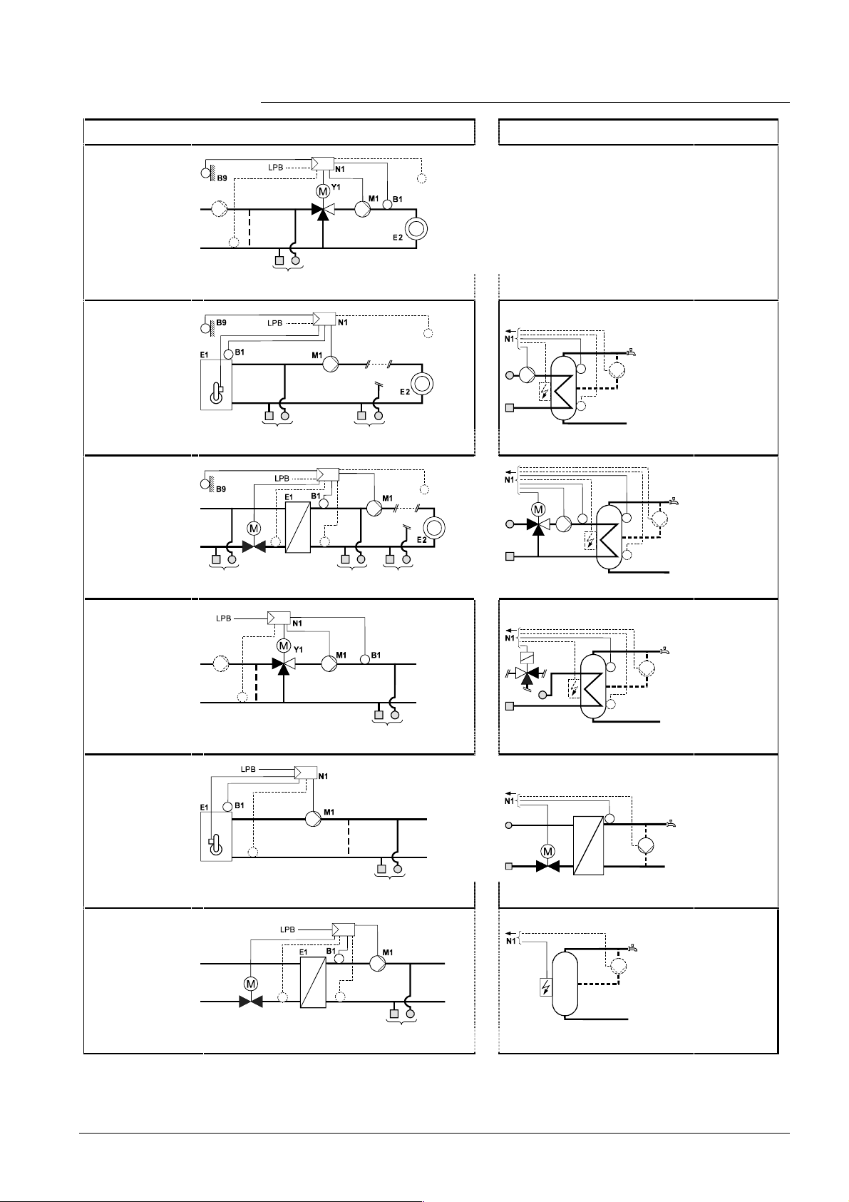
3.2.2 Heating circuit type 1 – space heating with mixing
valve
A6/B5
B7
2524S01
1, 2, 4 0, 5
Space heating with weather-compensated flow temperature control. 3-position control
acting on the mixing valve of the heating zone.
Outside temperature signal from own sensor or data bus. With or without room influence. Heating up and setback according to the heating program.
3.2.3 Heating circuit type 2 – space heating with boiler
A6/B5
2524S02
1, 2 3 0, 5
Space heating with own boiler, with weather-compensated boiler temperature control.
2-position control acting on the burner.
Outside temperature signal from own sensor or data bus. With or without room influence. Heating up and setback according to the heating program.
17/118
Siemens Building Technologies Basic Documentation RVL471 CE1P2524E
HVAC Products 3 Fundamentals 23.10.2002
Page 18
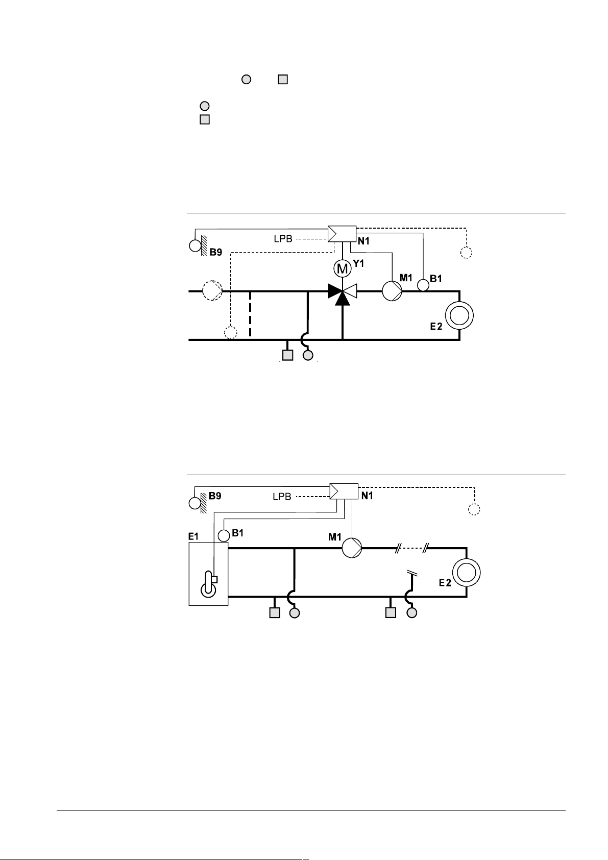
3.2.4 Heating circuit type 3 – space heating with district heat
N1
A6/B5
Y1
B7
B71
2524S03
2, 4 1 3 0, 5
Space heating with district heat connection, with weather-compensated flow temperature control acting on the valve in the primary return of the district heat connection.
Outside temperature signal from own sensor or data bus. With or without room influence. Heating up and setback according to the heating program.
3.2.5 Heating circuit type 4 – precontrol with mixing valve
B7
2524S04
1, 2 0, 5
Precontrol with demand-dependent control of the main flow temperature. 3-position
control acting on the mixing valve in the main flow.
Heat demand signal from data bus. No heating program.
3.2.6 Heating circuit type 5 – precontrol with boiler
B7
1, 2, 4 0, 5
Precontrol with demand-compensated control of the boiler temperature. 2-position control acting on the burner.
Heat demand signal from data bus. No heating program.
2524S05
18/118
Siemens Building Technologies Basic Documentation RVL471 CE1P2524E
HVAC Products 3 Fundamentals 23.10.2002
Page 19
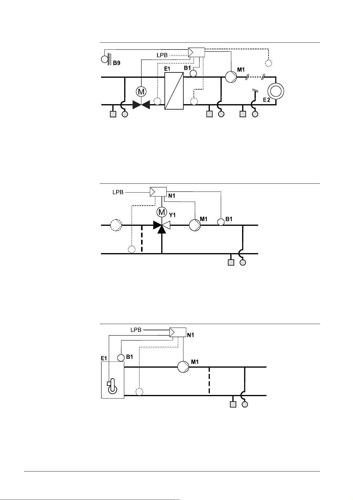
3.2.7 Heating circuit type 6 – precontrol with district heat
N1
Y1
2524S06
B7
Precontrol with district heat connection, with demand-compensated control of the secondary flow temperature acting on the valve in the primary return.
Heat demand signal from data bus. No heating program.
B71
1, 2 0, 5
3.2.8 D.h.w. plant type 0 – no d.h.w.
The RVL471 does not provide d.h.w. heating.
3.2.9 D.h.w. plant type 1 – d.h.w. storage tank with charging
pump
M3
B31
M4
K6
B32
Charging of d.h.w. storage tank through control of the charging pump. Acquisition of the
d.h.w. temperature with one or 2 sensors or thermostats. Circulating pump and electric
immersion heater are optional.
2524S07
3.2.10 D.h.w. plant type 2 – d.h.w. storage tank with mixing
valve
Y7
M3
B3
K6
B31
M4
B32
Charging of d.h.w. storage tank through control of the mixing valve according to own
temperature sensor in the storage tank flow. Acquisition of the d.h.w. temperature with
one or 2 sensors or thermostats. Circulating pump and electric immersion heater are
optional.
Siemens Building Technologies Basic Documentation RVL471 CE1P2524E
HVAC Products 3 Fundamentals 23.10.2002
2524S08
19/118
Page 20

3.2.11 D.h.w. plant type 3 – storage tank with diverting valve
Y3
B31
M4
K6
B32
2524S09
Charging of the d.h.w. storage tank through control of the diverting valve. Acquisition of
the d.h.w. temperature with one or 2 sensors or thermostats. Circulating pump and
electric immersion heater are optional.
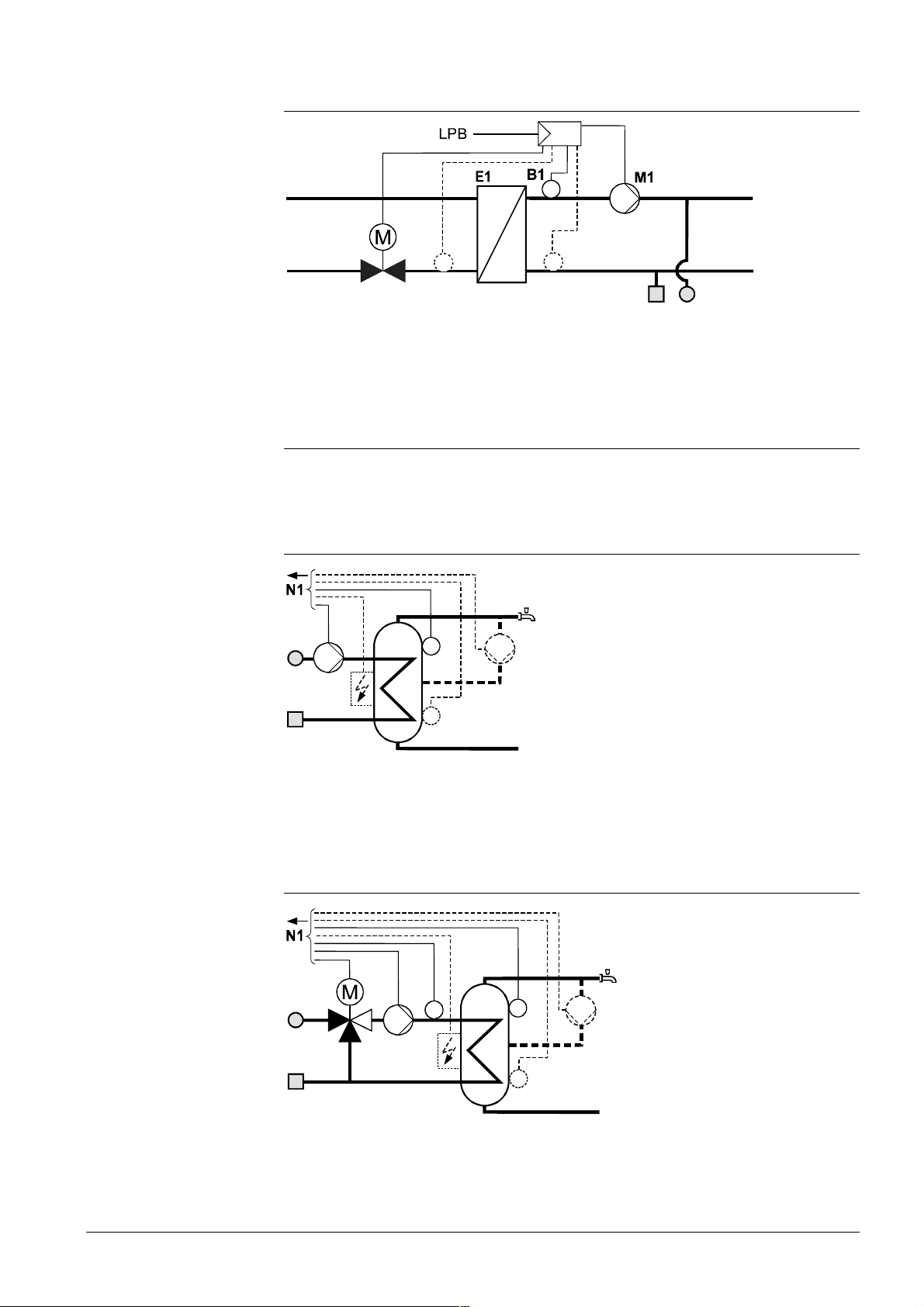
3.2.12 D.h.w. plant type 4 – instantaneous d.h.w. heating via
heat exchanger
N1
B3
Y7
D.h.w. heating via heat exchanger (instantaneous d.h.w. heating) through control of the
2-port valve in the heat exchanger’s primary return. Acquisition of the d.h.w. temperature in the heat exchanger’s secondary flow. Circulating pump is optional, but strongly
recommended.
M4
2524S10
3.2.13 D.h.w. plant type 5 – only electric immersion heater
M4
K6
2524S11
Charging of d.h.w. storage tank only through release of the electric immersion heater.
No control of d.h.w. heating by the controller. Circulating pump is optional.
A6 Room unit QAW50 or QAW70 E2 Consumer (space)
B1 Flow / boiler sensor LPB Data bus
B3 D.h.w. flow sensor K6 Electric immersion heater
B31 Storage tank sensor / thermostat 1 M1 Heating circuit pump / circulating pump
B32 Storage tank sensor / thermostat 2 M3 Charging pump
B5 Room sensor M4 Circulating pump
B7 Return sensor (primary circuit) N1 Controller RVL471
B71 Return sensor (secondary circuit) Y1 Heating circuit mixing valve
B9 Outside sensor Y3 Diverting valve
E1 Heat source (boiler / heat converter) Y7 D.h.w. mixing valve
20/118
Siemens Building Technologies Basic Documentation RVL471 CE1P2524E
HVAC Products 3 Fundamentals 23.10.2002
Page 21
3.2.14 Summary of plant types and plant combinations
0, 5
0, 5
0, 5
0, 5
Plant types with regard to heating circuit D.h.w. plant types
1
Space heating with
mixing zone 3position control,
acting on mixing
valve
Space heating with
own boiler:
2
Space heating with
own boiler 2-position
contro l, acting on
burner
Possible d.h.w. combinations:
3
Space heating with
district heat
3-position control,
acting on valve
Possible d.h.w. combinations:
A6/B5
B7
2524S01
Õ 1, 2, 4
A6/B5
2524S02
Õ 1, 2 3 0, 5
N1
Y1
B7
B71
2, 4 1 3 0, 5
A6/B5
2524S03
--
--
--
0
No d.h.w. heating
1
D.h.w. heating
M3
B31
M4
K6
B32
2524S07
through control
of the charging
pump.
2
M4
2524S08
D.h.w. heating
through control
of the mixing
valve.
Y7
B3
M3
K6
B31
B32
4
Precontrol with mixing zone, heat demand signal via data
bus
Possible d.h.w. combinations:
5
Precontrol with
boiler, heat demand
signal v ia data bus
Possible d.h.w. combinations:
6
Precontrol with district heat, heat demand signal via data
bus
Possible d.h.w. combinations:
B7
Õ 1, 2
B7
Õ 1, 2, 4
N1
Y1
B7
B71
Õ 1, 2
--
Y3
B31
2524S04
K6
B32
M4
--
B3
2524S05
Y7
M4
--
M4
2524S06
K6
2524S11
3
D.h.w. heating
through control
of the diverting
valve
2524S09
4
D.h.w. heating
via heat exchanger
through control
of the valve
2524S10
5
D.h.w. heating
via electric
immersion
heater only
21/118
Siemens Building Technologies Basic Documentation RVL471 CE1P2524E
HVAC Products 3 Fundamentals 23.10.2002
Page 22
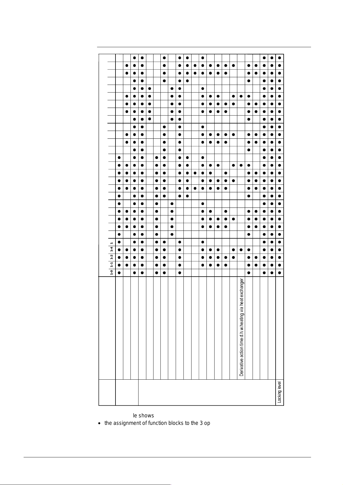
3.3 Setting levels, function blocks and plant
types
Combination of plants
2524T01e
1-0 1-1 1-2 1-4 1-5 2-0 2-1 2-2 2-3 2-5 3-0 3-1 3-2 3-3 3-4 3-5 4-0 4-1 4-2 4-5 5-0 5-1 5-2 5-4 5-5 6-0 6-1 6-2 6-5
Enduser general
Plant type
Function block
Enduser space heating
Enduser d.h.w.
Level
Enduser
Cascad e s l ave
Space heating
Setpoint limitation of return temperatu re
District heating
3-positio n actu ato r heati ng ci rc uit
Boiler
Max. limitat i on of d.h . w. re turn te mperature
Basic settings d.h.w.
Release of d.h.w. charging
D.h.w. s to rage tank
D.h.w. priority and flow temperature setpoint
3-position d.h.w. actuator
Heating
engineer
The above table shows
• the assignment of function blocks t o t he 3 op erat ing leve ls
• the function blocks activ at ed wit h the d ifferen t p lan t ty pes
U
H
J
Q
D
K
F
[
H
W
D
H
K
D
L
Y
J
Q
L
W
D
H
K
Z
K
G
H
P
L
W
Q
R
L
W
F
D
H
Y
L
W
D
Y
L
U
H
Multifunctional relay
Time switch pro gram 3
Legionella function
'
Service fu nct io ns and gene ra l set tin gs
Locking function s
O
H
Y
H
O
J
Q
L
N
F
R
/
22/118
Siemens Building Technologies Basic Documentation RVL471 CE1P2524E
HVAC Products 3 Fundamentals 23.10.2002
Page 23

3.4 Heating circuit ope rating modes
The heating circuit operating mode is selected on the controller by pressing the respective button. Also, the operating mode can be changed by bridging terminals H1-M.
3.4.1 Automatic operation
• Automatic changeover from NORMAL to REDUCED temperature, and vice versa,
according to the 7-day program entered
• Automatic changeover to holiday mode, and back, according to the holiday schedule
entered
• Demand-dependent switching of the heating system according to the room and outside
temperature while giving consideration to the building’s thermal inertia (ECO function)
• Remote operation via room unit (optional)
• Frost protection is ensured
3.4.2 Continuously REDUCED heating
• Continuous heating to the REDUCED temperature
• With ECO function
• No holiday mode
• Remote operation from a room unit not possible
• Frost protection is ensured
3.4.3 Continuously NORMAL heating
• Continuous heating to NORMAL temperature
• No ECO function
• No holiday mode
• Remote operation via room unit not possible
• Frost protection is ensured
3.4.4 STANDBY
• Heating is switched off, but is ready to operate
• Frost protection is ensured
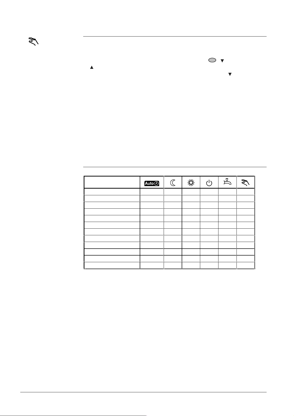
3.5 D.h.w. operati ng modes
D.h.w. heating is switched on and off by pressing the respective button:
• ON (button
operating mode and control. D.h.w. heating to the NORMAL or REDUCED setpoint
can be provided as follows:
− According to the entered switching program 2
− According to the entered heating circuit program (–1 h)
− Continuously (24 hours a day)
During the entered holiday period, d.h.w. heating and the circulating pump are deactivated when using controllers with no bus connection (with data bus, depending on
the setting made).
• OFF (button
tion of plant types x–4 and x–5)
is lit): D.h.w. heating takes place independent of the heating circuit’s
dark): No d.h.w. heating. Frost protection is ensured (with the excep-
23/118
Siemens Building Technologies Basic Documentation RVL471 CE1P2524E
HVAC Products 3 Fundamentals 23.10.2002
Page 24
3.6 Manual operation
The RVL471 can be switched to manual operation. In this case, the control will be
switched off. In manual operation, the various actuating devices behave as follows:
• Heating circuit mixing valve: This mixing valve is not under voltage, but can be manually driven to any position by pressing the manual buttons
= opening). The heating circuit pump / circulating pump is continuously running.
• Boiler: The 2 burner stages are continuously on. The manual button
switch the second stage on and off. Pump M1 is continuously running
• D.h.w. charging pump: The charging pump is continuously running
• D.h.w. changeover valve: The diverting valve is always in the ”Heating circuit” position
• D.h.w. slipper / seat valve: This valve is driven to the fully closed position, in which
case the closing time is five times the set running time. Then, it is deactivated
• Circulating pump M4: Continuously running
• Electric immersion heater K6: Continuously released
• Multifunctional relay: Continuously energized
Manual operation also negates any overriding of the controller's operating mode
(bridging of H1–M).
( = closing,
can be used to
3.7 Plant type and operating mode
Depending on the selected type of plant, the following operating modes are available:
Plant type
1–0 YES YES YES YES NO YES
1–1, 1–2, 1–4, 1–5 YES YES YES YES YES YES
2–0 YES YES YES YES NO YES
2–1, 2–2, 2–3, 2–5 YES YES YES YES YES YES
3–0 YES YES YES YES NO YES
3–1, 3–2, 3–3, 3–4, 3–5 YES YES YES YES YES YES
4–0 YES NO NO NO NO YES
4–1, 4–2, 4–5 YES NO NO NO YES YES
5–0 YES NO NO *) NO YES
5–1, 5–2, 5–4, 5–5 YES NO NO *) YES YES
6–0 YES NO NO NO NO YES
6–1, 6–2, 6–5 YES NO NO NO YES YES
*)
Depending on the boiler's operating mode:
Boiler with automatic shutdown: NO
Boiler with manual shutdown: YES
24/118
Siemens Building Technologies Basic Documentation RVL471 CE1P2524E
HVAC Products 3 Fundamentals 23.10.2002
Page 25
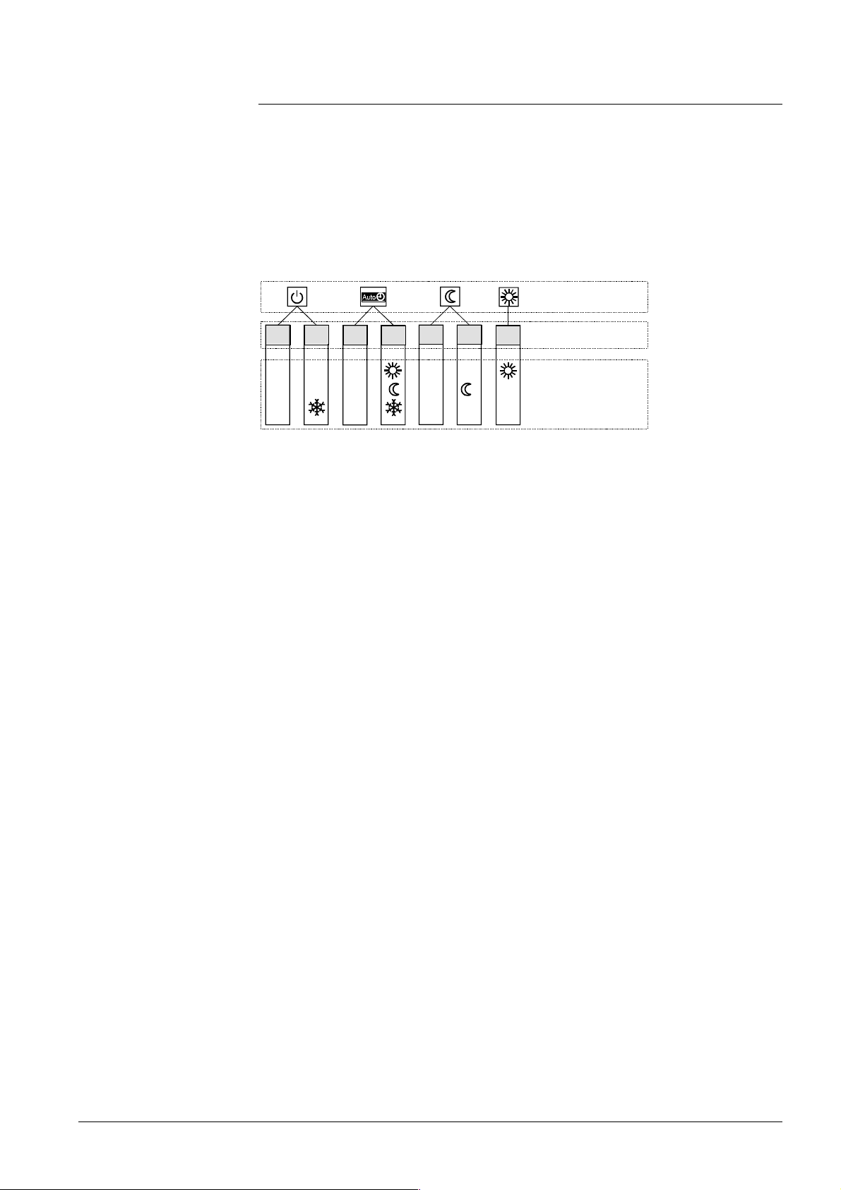
3.8 Operating state and operational level
The user selects the required heating circuit operating mode by pressing the respective
button. Each operating state has a maximum of 2 operating states – with the exception
of operating mode "Continuously NORMAL heating" (only one operating state possible).
When the ECO function is active, and in the case of quick setback, the operating state
is always OFF.
When the operating state is ON, there is a maximum of 3 operational levels, depending
on the operating mode. The operational level is determined by the heating program and
the holiday program.
Operat i n g mo de
OFF
ON
OFF
ON
OFF ON
ON
Operating stat e
Operational le v e l
2522B03e
25/118
Siemens Building Technologies Basic Documentation RVL471 CE1P2524E
HVAC Products 3 Fundamentals 23.10.2002
Page 26

4 Acquisition of measured values
4.1 Room temperature (A6, B5)
4.1.1 Measurement
The following choices exist:
• A room temperature sensor QAA24 can be connected to terminal B5
• A room unit QAW50 or QAW70 can be connected to terminal A6
• 2 units can be connected to the terminals. In this case, the RVL471 can ascertain the
average of the 2 measurements. The other room unit functions will not be affected by
averaging
4.1.2 Handling faults
If there is a short-circuit or open-circuit in one of the 2 measuring circuits, the control
responds as follows, depending on the room temperature source (setting on operating
line 65):
• No sensor (operating line 65 = 0):
A short-circuit or open-circuit has no impact on the control. An error message will not
be generated
• Room unit sensor QAW... (operating line 65 = 1):
In the event of a short-circuit or open-circuit, the control continues to operate with the
room model, depending on the function. An error message will be generated
• Room temperature sensor QAA24 (operating line 65 = 2):
In the event of a short-circuit or open-circuit, the control continues to operate with the
room model, depending on the function. An error message will be generated
• Average value (operating line 65 = 3):
In the event of a short-circuit or open-circuit in one of the 2 measuring circuits, the
control continues to operate with the normally working measuring circuit. An error
message will be generated.
In the case of a short-circuit or open-circuit in both measuring circuits, the control continues to operate with the room model, depending on the function. 2 error messages
will be generated
• Automatic mode (operating line 65 = A):
Since the controller itself decides how it acquires the room temperature, error messages cannot be generated.
4.1.3 Room model
The RVL471 features a room model. It simulates the progression of the room temperature. In plants with no measurement of the room temperature, it can provide certain
room functions (e.g. quick setback).
For more detailed information, refer to section 10.4.4, "Room model temperature".
4.2 Flow and boiler temperatur e (B1)
4.2.1 Measurement
The flow or boiler temperature is acquired with one or 2 sensors. 2 sensors connected
in parallel are used to ascertain the average value. The temperature sensors used must
always have a sensing element LG-Ni
26/118
Siemens Building Technologies Basic Documentation RVL471 CE1P2524E
HVAC Products 4 Acquisition of measured values 23.10.2002
Page 27

4.2.2 Handling faults
A short-circuit or open-circuit in the measuring circuit is identified and indicated as a
fault. In that case, the plant responds as follows:
• Plants with 3-position control:
Heating circuit pump / circulating pump M1 continues to run and the mixing valve will
close
• Plants with 2-position control:
The heating circuit pump / circulating pump M1 continues to run and the burner will
shut down
4.3 Outside temperature (B9)
4.3.1 Measurement
The outside temperature is acquired with the outside sensor. This can be a QAC22 or
QAC32:
• QAC22: Sensing element LG-Ni 1000
• QAC32: Sensing element NTC 575 at 20 °C
The controller automatically identifies the type of sensor used.
In interconnected plants, the outside temperature signal is made available via LPB.
Controllers having their own sensor pass the outside temperature signal to the data
bus.
DW&
4.3.2 Handling faults
If there is a short-circuit or open-circuit in the measuring circuit, the controller responds
as follows, depending on the outside temperature source:
• Controller not connected to the data bus (LPB):
The control operates with a fixed value of 0 °C outside t emperature. An error message
will be generated
• Controller connected to the data bus (LPB):
If the outside temperature is available via data bus, it will be used. An error message
will not be generated (this is the normal state in interconnected plants!). If there is no
outside temperature available on the data bus, however, the control uses a fixed value
of 0 °C outside temperature. In that case, an error message will be generated.
4.4 Primary return temperature (B7)
4.4.1 Measurement
The primary return temperature is acquired with a sensor having a sensing element LGNi 1000
primary return temperature and for limitation of the temperature differential (DRT limitation).
In interconnected plants, the primary return temperature with plant type 1–x can be
acquired via data bus. Controllers with plant type 1–0 and connected sensor pass the
return temperature signal to the data bus.
7KLVPHDVXUHGYDOXHLVUHTXLUHGIRUPLQLPXPDQGPD[LPXPOLPLWDWLRQRIWKH
4.4.2 Handling faults
If there is a short-circuit or open-circuit in the measuring circuit, and if the controller
requires the return temperature, it responds as follows:
27/118
Siemens Building Technologies Basic Documentation RVL471 CE1P2524E
HVAC Products 4 Acquisition of measured values 23.10.2002
Page 28

• If there is a return temperature from a controller of the same segment available on the
data bus, it is used (only with plant type 1–x). No error message will be generated
since this is the normal state in interconnected plants
• However, if there is no return temperature available on the data bus, the return temperature limitation functions will be deactivated and an error message generated
4.5 Secondary return temperature (B71)
4.5.1 Measurement
The secondary return temperature is acquired with a sensor having a sensing element
LG-Ni 1000
6–x), together with the primary return temperature.
7KLVPHDVXUHGYDOXHLVUHTXLUHGIRU'57OLPLWDWLRQSODQWW\SHV±[DQG
4.5.2 Handling faults
If there is a short-circuit or open-circuit in the measuring circuit, and if the controller
requires the return temperature, DRT limitation will be deactivated. An error message
will be generated
4.6 D.h.w. flow temperatu re (B 3)
4.6.1 Measurement
The d.h.w. flow temperature is acquired with a sensor having a sensing element
LG-Ni 1000
4.6.2 Handling faults
If there is a short-circuit or open-circuit in the measuring circuit, the d.h.w. will no longer
be heated. The charging pump is deactivated and the actuating device (slipper or seat
valve) is shut.
An error message will be generated.
4.7 D.h.w. storage tank temperature (B31, B32)
4.7.1 Measurement
The storage tank temperature can be acquired as follows:
• With one or 2 sensors having a sensing element LG-Ni 1000
• With one or 2 thermostats
This means that there are 2 measuring circuits.
RU
4.7.2 Handling faults
The controller's response to faults in the measuring circuits depends on the type of
d.h.w. demand (setting on operating line 126):
• One d.h.w. storage tank temperature sensor (operating line 126 = 0):
In the event of a short-circuit or open-circuit in one of the 2 measuring circuits, the
controller continues to work with the other measuring circuit, if possible. An error message will not be generated.
28/118
Siemens Building Technologies Basic Documentation RVL471 CE1P2524E
HVAC Products 4 Acquisition of measured values 23.10.2002
Page 29

If no valid measured value is obtained from either of the measuring circuits, an error
message will be generated. The d.h.w. will no longer be heated and the charging pump
is deactivated.
Exception: With plant type x–2, the d.h.w. storage tank is always charged when sensor
B3 (d.h.w. flow) works normally
• 2 d.h.w. storage tank temperature sensors (operating line 126 = 1):
In the event of a short-circuit or open-circuit in one of the 2 measuring circuits, the
controller continues to work with the other measuring circuit. An error message will be
generated.
If no valid measured value is obtained from either of the measuring circuits, 2 error
messages will be generated. The d.h.w. will no longer be heated and the charging
pump is deactivated.
Exception: With plant type x–2, the d.h.w. storage tank is always charged when sensor
B3 (d.h.w. flow) works normally
• One d.h.w. storage tank thermostat (operating line 126 = 2):
If, in measuring circuit B31, there is neither an open-circuit (thermostat open) nor a
short-circuit (thermostat closed), an error message will be generated. The d.h.w. will no
longer be heated and the charging pump is deactivated.
Exception: With plant type x–2, the d.h.w. storage tank is always charged when sensor
B3 (d.h.w. flow) works normally
• 2 d.h.w. storage tank thermostats (operating line 126 = 3):
If, in the measuring circuits, there is neither an open-circuit (thermostat open) nor a
short-circuit (thermostat closed), an error message will be generated. The controller
will continue to work with the measuring circuit that operates correctly.
If, in both measuring circuits, there is neither an open-circuit (thermostat open) nor a
short-circuit (thermostat closed), 2 error messages will be generated. The d.h.w. will no
longer be heated and the charging pump is deactivated.
Exception: With plant type x–2, the d.h.w. storage tank is always charged when sensor
B3 (d.h.w. flow) works normally
29/118
Siemens Building Technologies Basic Documentation RVL471 CE1P2524E
HVAC Products 4 Acquisition of measured values 23.10.2002
Page 30

5 Function block "Enduser space heat-
ing"
This function block contains settings that the enduser himself can make.
5.1 Operating lines
Line Function, par amet er Unit Factory
1 Setpoint of NORMAL heating °C 20.0 0...35
2 Setpoint of REDUCED heating °C 14.0 0...35
3 Setpoint of holiday mode / frost protection °C 10.0 0...35
4 Weekday for th e heating program 1-7 1...7, 1-7
5 1. Third heating period, start of NORMAL heating hh:mm 06:00 --:-- / 00:00...24:00
6 1. Third heat i ng per i od, start of REDUCED heating hh:mm 22:00 --:-- / 00:00...24:00
7 2. Third heating period, start of NORMAL heating hh:mm --:-- --:-- / 00:00...24:00
8 2. Third heat i ng per i od, start of REDUCED heating hh:mm --:-- --:-- / 00:00...24 :00
9 3. Third heating period, start of NORMAL heating hh:mm --:-- --:-- / 00:00...24:00
10 3. Third he at i ng per i od, start of REDUCED heating hh:mm --:-- --:-- / 00:00...24 :00
11 Holiday period 1...8
12 Date of first day of holiday dd:MM --:-- --:-- / 01.01. ... 31.12.
13 Date of last day of holiday dd:MM --:-- --:-- / 01.01. ... 31.12.
14 Heat i ng cu rv e, f low tem pe r at ure s et poin t TV 1 at
an outside temperature of 15 °C
15
Heating cu rv e, flo w tem pe rat ur e set po in t TV2 at
an outside temperature of –5 °C
°C 30 20...70
°C 60 20...120
setting
Range
5.2 Setpoints
5.2.1 General
The setpoints of the NORMAL and the REDUCED room temperature and of frost protection for the plant / holiday mode are entered directly in °C room temperature. They
are independent of whether or not the control uses a room temperature sensor.
Caution
5.2.2 Frost protection for the building
The lowest valid room temperature setpoint always corresponds to at least the setpoint
of holiday mode / frost protection (setting on operating line 3), even if lower values have
been entered as the setpoints of the NORMAL and the REDUCED room temperature
(settings on operating lines 1 and 2).
If a room sensor is used and the room temperature falls below the holiday / frost protection setpoint, ECO – if available – will stop OFF until the room temperature has risen
1 °C above the holiday / frost protection setpoint.
5.3 Heating program
The heating program of the RVL471 provides a maximum of 3 heating periods per day;
also, every weekday may have different heating periods.
The entries to be made are not the switching times, but the periods of time during which
the NORMAL room temperature shall apply. Usually, these periods of time are identical
to the building's occupancy times. The actual switching times for the change from the
REDUCED to the NORMAL room temperature, and vice versa, are calculated by the
optimization function. (Precondition: Optimization is activated).
30/118
Siemens Building Technologies Basic Documentation RVL471 CE1P2524E
HVAC Products 5 Function block "Enduser space heating" 23.10.2002
Page 31

Using the setting "1-7" on operating line 4, it is possible to enter a heating program that
applies to all weekdays. This simplifies the settings: If the weekend times differ, enter
the times for the entire week first, and then change days 6 and 7 as required.
The settings are sorted and overlapping heating periods combined.
5.4 Holiday program
A maximum of 8 holiday periods per year can be programmed. At 00:00 of the first day
of the holiday period, changeover to the setpoint for frost protection / holiday mode
takes place. At 24:00 of the last day of the holiday period, the RVL471 will change to
NORMAL or REDUCED heating in accordance with the time switch settings.
The settings of each holiday period will be cleared as soon as the respective period has
elapsed.
Holiday periods may overlap. It is not necessary to observe a certain order. Depending
on the entry made on operating line 121, the holiday function will switch off d.h.w.
heating and the circulating pump.
The holiday program is only active in AUTO mode.
31/118
Siemens Building Technologies Basic Documentation RVL471 CE1P2524E
HVAC Products 5 Function block "Enduser space heating" 23.10.2002
Page 32

6 Function block "Enduser d.h.w."
This function block contains settings for d.h.w. heating that the enduser himself can
make.
6.1 Operating lines
Line Function, par amet er Unit
26 Setpoint of NORMAL d.h.w. temperature °C 55 20...100
27 D.h.w. temperature Display function
28 Setpoint of REDUCED d.h.w. temperature °C 40 8...80
Factory
setting
Range
6.2 Setpoint
The NORMAL and REDUCED d.h.w. temperature setpoints are to be entered in °C.
When using thermostats, it must be made certain that the NORMAL setpoint entered
here agrees with the setpoint of the thermostat or – if 2 thermostats are used – of both
thermostats. If there is a deviation, the charging temperature cannot be correctly calculated (charging temperature = NORMAL setpoint [operating line 26] + boost of
charging temperature [operating line 127]).
If d.h.w. heating is switched to the electric immersion heater, the setpoint adjustment is
inactive in that case, since the thermostat of the electric immersion heater will ensure
temperature control of the storage tank.
6.3 Actual value
The d.h.w. temperature is displayed in °C as follows, depending on the type of plant:
Plant type Display
x–1, x–2, x–3 B31 or maximum selection of the 2 storage tank sensors B31 and
B32
x-4 D.h.w. flow temperature sensor B3
If the measurement is made with one or 2 thermostats, it is not possible to display the
actual value. In that case, the display shows ---.
32/118
Siemens Building Technologies Basic Documentation RVL471 CE1P2524E
HVAC Products 6 Function block "Enduser d.h.w." 23.10.2002
Page 33

7 Function block "Enduser general"
This function block contains settings that the enduser himself can make, as well as
indication of faults.
7.1 Operating lines
Line Function, par amet er Unit
31 Weekday for switching program 2 1-7 1...7, 1-7
32 Start of first ON period hh: mm 05:00 --:-- / 00:00...24:00
33 End of first ON period hh:mm 22:00 --:-- / 00:00...24:00
34 Start of second ON period hh:mm --:-- --:-- / 00:00...24:00
35 End of second ON period hh:mm --:-- --:-- / 00:00...24:00
36 Start of third ON period hh:mm --:-- --:-- / 00:00...24:00
37 End of third ON period hh:mm --:-- --:-- / 00:00...24:00
38 Time of day hh:mm 00:00...23:59
39 Weekday 1...7
40 Date dd:MM 01.01. ... 31.12.
41 Year jjjj 1995...2094
50 Indication of errors 0...255
Factory
setting
Range
7.2 Switching program 2
Switching program 2 can be used for one or several of the following functions:
• As a time switch program for the circulating pump
• As a time switch program for the release of d.h.w. heating
• As a time switch program for the multi-functional relay
Switching program 2 of the RVL471 affords a maximum of three ON periods per day.
Also, every day of week may have different ON periods.
As with the heating program, it is not the "switching times" that are to be entered, but
the periods of time during which the program or the controlled function shall be active.
Using setting "1-7" on operating line 31, it is possible to enter a switching program that
applies to all weekdays. This simplifies the settings: if the weekend times are different,
first enter the times for the entire week, then change days 6 and 7 as required.
The entries are sorted and overlapping ON periods combined.
7.3 Time of day and date
The RVL471 has a yearly clock to enter the time of day, weekday and date.
The changeover from summer- to wintertime, and vice versa, takes place automatically.
Should the respective standards change, the changeover dates can be adjusted (refer
to chapter "25 Function block "Service functions and general settings"
33/118
Siemens Building Technologies Basic Documentation RVL471 CE1P2524E
HVAC Products 7 Function block "Enduser general" 23.10.2002
Page 34

7.4 Indication of errors
The following errors are indicated:
Number Fault
10 Open-circuit or short-circuit in the outside sensor’s measuring circuit (B9)
30 Open-circuit or short-circuit in the measuring circuit of the flow / boiler
sensor (B1)
40 Open-circuit or short-circuit in the measuring circuit of the return tem-
perature sensor on the primary side (B7)
42 Open-circuit or short-circuit in the measuring circuit of the return tem-
perature sensor on the secondary side (B71)
50 Fault in the measuring circuit of the d.h.w. storage tank sensor / thermo-
stat 1 (B31)
52 Fault in the measuring circuit of the d.h.w. storage tank sensor / thermo-
stat 2 (B32)
54 Open-circuit or short-circuit in the measuring circuit of the d.h.w. sensor
(B3)
60 Open-circuit or short-circuit in the measuring circuit of the room sensor
(B5)
61 Open-circuit or short-circuit in the measuring circuit of the room unit’s
sensor (A6)
62 Wrong room unit connected
81 Short-circuit on data bus (LPB)
82 Bus address on the data bus (LPB) exists several times
100 2 clock masters on the data bus (LPB)
120 Flow alarm (for explanation, refer to function block "Service functions and
general settings")
140 Inadmissible bus address or inadmissible plant type
If a fault occurs, the LCD displays ERROR.
In interconnected plants, the address (device and segment number) of the controller
causing the fault is indicated on all the other controllers. No address will appear on the
controller causing the fault.
Example of display in interconnected plants:
50
= operat ing line
10
= error number
2
= segment number
03
= device number
The error message disappears only after rectification of the fault. There will be no acknowledgement!
34/118
Siemens Building Technologies Basic Documentation RVL471 CE1P2524E
HVAC Products 7 Function block "Enduser general" 23.10.2002
Page 35

8 Function block "Plant type"
This function block only contains the selection of the plant type.
8.1 Operating line
Line Function, par amet er Unit
51 Plant type 1−1 1−0 ... 6−5
Factory
setting
Range
8.2 General
When commissioning the plant, the respective plant type must be entered first. This
ensures that the functions required for the specific type of plant, the parameters and
operating lines for the settings and displays will be activated.
All plant-specific variables and operating lines existing for the other plant types will then
be hidden. They will not be displayed.
Example for an entry (selection of plant type 1–2)
12= heating circuit type 1
= d.h.w. circuit type 2
35/118
Siemens Building Technologies Basic Documentation RVL471 CE1P2524E
HVAC Products 8 Function block "Plant type" 23.10.2002
Page 36

9 Function block "Cascade slave"
This function block facilitates integration of the controller as a cascade slave into a heat
source cascade. A heat source cascade is the combined operation of several oil- / gasfired boilers.
9.1 Operating lines
Line Function, par amet er Unit Factory
setting
59 Release integral for boiler sequence °C*min 200 0...500
60 Reset integral of boiler sequence °C*min 50 0...500
Range
9.2 Mode of operation
The surplus heat or heat deficit of the boiler is ascertained with the help of the boiler
sequence integral and communicated to the cascade master via LPB.
9.2.1 Boiler sequence release integral (KFI)
The boiler sequence release integral is a variable generated from the progression of
the cascade flow temperature and time (t). If the variable falls below the setpoint, the
difference will be communicated to the cascade master as the heat deficit.
t
KFI =
TVKw Flow temperature setpoint of the cascade
TVKx Actual value of cascade flow temperature
SD Switching differential of the boiler
tTime
∆Tdt
∫
0
where: ∆T = ( T
− 0,5 * SD − T
VKw
VKx
) > 0
Note
9.2.2 Boiler sequence re set integral (KRI)
The boiler sequence reset integral is a variable generated from the progression of the
cascade flow temperature and time (t). If the variable exceeds the setpoint, the difference will be communicated to the cascade controller as surplus heat.
t
KRI =
Automatic boiler sequence changeover according to the number of burner operating
hours is not possible with the RVL471 since this controller does not acquire the number
of burner operating hours. Boiler management functions must be provided in the cascade master.
∆Tdt
∫
0
where: ∆T = ( T
VKx
− T
+ 0.5 * SD ) > 0
VKw
36/118
Siemens Building Technologies Basic Documentation RVL471 CE1P2524E
HVAC Products 9 Function block "Cascade slave" 23.10.2002
Page 37

10 Function block "Space heating"
This function block performs the ECO function, the optimization functions with boost
heating and quick setback, as well as the room influence.
10.1 Operating lines
Line Function, par amet er Unit
61 Heating limit for NORMAL heating (ECO day) °C 17.0 --.- / −5...+25
62 Heati ng l im it for REDUCED h eating (ECO night) °C 5.0 --.- / –5...+25
63 Building time constant h 20 0...50
64 Quick setback 1 0 / 1
65 Room temperature source A 0 / 1 / 2 / 3 / A
66 Type of optimization 0 0 / 1
67 Maximum heating up time hh:mm 00:00 00:00...42:00
68 Maximum early shutdown hh:mm 0:00 0:00...6:00
69 Maximum limitation of room temperature °C --.- --.- / 0...35
70 Gain factor of room influence 4 0...20
71 Boost of room temperature setpoint °C 5 0...20
72 Parallel di s placeme nt of the heat ing curve °C 0.0 −4.5...+4.5
73 Heating curve slope 0 0...2
Factory
setting
Range
10.2 ECO function
The ECO function controls space heating depending on demand. It gives consideration
to the progression of the room temperature depending on the type of building construction as the outside temperature varies. If the amount of heat stored in the house or
building is sufficient to maintain the room temperature setpoint currently required, the
ECO function will switch the heating off.
When using the ECO function, the heating system operates only, or consumes energy
only, when required.
10.2.1 Compensating variables and auxiliary variables
As compensating and auxiliary variables, the ECO function takes into account the development of the outside temperature and the heat storage capacity of the building.
The following variables are taken into consideration:
• The building time constant: this is a measure of the type of building construction and
indicates how quickly the room temperature would change if the outside temperature
was suddenly changed. The following guide values can be used for setting the building
time constant: 10 hours for light, 25 hours for medium, and 50 hours for heavy building
structures
• The actual outside temperature (T
• The composite outside temperature (T
− the actual outside temperature, and
− the outside temperature filtered by the building time constant
Compared with the actual outside temperature, the composite outside temperature is
attenuated. Hence, it represents the effects of short-time outside temperature variations on the room temperature as they often occur during intermediate seasons
(spring and autumn)
• The attenuated outside temperature (T
outside temperature by the building time constant. This means that, compared with the
actual outside temperature, the attenuated outside temperature is considerably dampened. This ensures that no heating will take place in the summer when, under normal
circumstances, the heating would be switched on because the outside temperature
drops for a few days
)
A
), which is the mean value of:
AM
): it is generated by filtering twice the actual
AD
37/118
Siemens Building Technologies Basic Documentation RVL471 CE1P2524E
HVAC Products 10 Function block "Space heating" 23.10.2002
Page 38

TA (B9 rsp. BUS)
T
A
k
k
t
t
T
AM
2522B02
T
AD
Generation of the composite and attenuated outside temperature
TAActual outside temperature
T
Attenuated outside temperature
AD
T
Composite outside temperature
AM
Building time constant
k
t
T
A
25
20
15
10
T
AD
5
0
T
A
T
AM
2522D17
t
Switching the heating off
Progression of the actual, composite and attenuated outside temperature
TAActual outside temperature
T
Attenuated outside temperature
AD
T
The comp osite outside tempe rature
AM
tTime
10.2.2 Heating limits
The following heating limits can be set:
• "ECO day" for NORMAL heating
• "ECO night" for the lower temperature level. This can be REDUCED heating or OFF
(holidays / frost protection)
In both cases, the heating limit is the outside temperature at which the heating shall be
switched on and off. The switching differential is 1 °C.
10.2.3 Mode of operation
The heating will be switched off when one of the 3 following conditions is satisfied:
• The actual outside temperature exceeds the current ECO heating limit
• The composite outside temperature exceeds the current ECO heating limit
• The attenuated outside temperature exceeds the "ECO day" heating limit
In all these cases, it is assumed that the amount of heat entering the building envelope
from outside or the amount of heat stored in the building structure will be sufficient to
maintain the required room temperature level.
When the ECO function has switched the heating off, the display shows
ECO.
Switching the heating on
The heating will be switched on again only when all 3 of the following conditions are
satisfied:
38/118
Siemens Building Technologies Basic Documentation RVL471 CE1P2524E
HVAC Products 10 Function block "Space heating" 23.10.2002
Page 39

• The actual outside temperature has fallen 1 °C below the current ECO heating limit
• The composite outside temperature has fallen 1 °C below the current ECO heating
limit
• The attenuated outside temperature has fallen 1 °C below the "ECO day" heating limit
10.2.4 Operating modes and operating states
The ECO function is performed depending on the operating mode:
Operating mode or operating state
Automatic operation active ECO day or ECO night
Continuously REDUCED heating active ECO night
Continuously NORMAL heating inactive –
STANDBY
Frost protection / holiday mode active ECO night
Manual operation
ECO function Current heating limit
active ECO night
inactive –
10.3 Room temperature source
The outside temperature source can be selected on operating line 65.
The following settings are available:
Operating line 65 SET
0 No room sensor
1 Room unit at terminal A6
2 Room sensor connected to terminal B5
3 Average of devices connected to A6 and B5
A Automatic selection
Operating line 65 also displays the room temperature source actually used by the controller (ACTUAL).
ACTUAL = 0 = controller operates without a sensor
ACTUAL = 1 = controller operates with a room unit connected to terminal A6
ACTUAL = 2 = controller operates with a room sensor connected to terminal B5
ACTUAL = 3 = controller operates with the mean value of the devices connected to
A6 and B5
Room temperature source
10.4 Optimization
10.4.1 Definition and purpose
Operation of the heating system is optimized. According to EN 12 098, optimization is
the "automatic shifting of the switch-on and switch-off points aimed at saving energy".
This means that:
• Switching on and heating up as well as switching off are controlled such that during
building occupancy times the required room temperature level will always be ensured
• The smallest possible amounts of energy will be used to achieve this objective
10.4.2 Fundamentals
It is possible to select or set:
• The type of optimization: either with a room sensor / room unit or based on the room
model
39/118
Siemens Building Technologies Basic Documentation RVL471 CE1P2524E
HVAC Products 10 Function block "Space heating" 23.10.2002
Page 40

• The maximum limit value for the heating-up time
• The maximum limit value for optimum shutdown
• Quick setback: Yes or no
To perform the optimization function, the controller makes use of the actual room temperature – acquired by a room temperature sensor or room unit – or the room model.
With room sensor
Without room sensor
Using a room sensor or room unit, it is possible to have optimum start and optimum
stop control.
To be able to optimally determine the switch-on and switch-off points, optimization
needs to "know" the building's heating up and cooling down characteristics, always as a
function of the prevailing outside temperature. For this purpose, optimization continually
acquires the room temperature and the respective outside temperature. It captures
these variables via the room temperature sensor and the outside sensor and continually adjusts the forward shift of the switching points. In this ways, optimization can also
detect changes made to the house or building and to take them into consideration.
The learning process always concentrates on the first heating period per day.
When no room temperature sensor is used, the room model only allows optimum start
control.
Optimization operates with fixed values (no learning process), based on the set maximum heating up time and the room model.
10.4.3 Process
T
Rw
T
Rw
T
Rw
T
Rw
T
Rx
HP
HP Heating program
Room temperature
T
R
tTime
t
Forward shift for early shutdown
1
t
Forward shift for the start of heating up
2
t
Quick setback
3
TRw Room temperature setpoint
T
Setpoint of NORMAL room temperature
Rw
T
Setpoint of REDUCED room temperature
Rw
∆TRw Boost of room temperature setpoint (with boost heating)
TRx Actual value of the room temperature
10.4.4 Room model temperature
To ascertain the room temperature generated by the room model, a distinction must be
made between 2 cases:
• The RVL471 is not in quick setback mode:
The room temperature generated by the room model is identical to the current room
temperature setpoint
40/118
Siemens Building Technologies Basic Documentation RVL471 CE1P2524E
HVAC Products 10 Function block "Space heating" 23.10.2002
Page 41

• The RVL471 is in setback mode:
The room temperature generated by the room model is determined according to the
following formula:
t
Room model temperature TRM [ °C ] = (TRw - TAM )
T
Rw
T
T
Rw
T
Rw
RM
t
1
3 * kt
e
*
2522D18
+ T
AM
Progression of room temperature generated by the room model
where:
e 2.71828 (basis of natural logarithms)
k
Building time constant in hours
t
t Time in hours
t
Quick setback
1
Composite outside temperature
T
AM
T
Room temperature
R
Room model temperature
T
RM
Setpoint of NORMAL room temperature
T
Rw
Setpoint of REDUCED room temperature
T
Rw
10.4.5 Optimum stop control
During the building's occupancy time, the RVL471 maintains the setpoint of NORMAL
heating. Towards the end of the occupancy time, the control switches to the REDUCED
setpoint. Optimization calculates the changeover time such that, at the end of occupancy, the room temperature will lie 0.5 °C below the setpoint of NORMAL heating
(optimum shutdown).
By entering 0 hours as the maximum optimum shutdown, optimum stop control can be
deactivated.
10.4.6 Quick setback
When changing from the NORMAL temperature to a lower temperature level
(REDUCED or holidays / frost), the heating will be shut down. And it will remain shut
down until the setpoint of the lower temperature level is reached.
• When using a room temperature sensor, the effective actual value of the room temperature is taken into account
• When using no room sensor, the actual value is simulated by the room model.
The duration is determined according to the following formula:
T
– T
t [ h ] = 3 * kt
(– ln
*
Rw
T
Rw
where:
ln Natural logarithm T
k
Building time constant in hours
t
t Duration of quick setback
– T
AM
AM
)
Composite outside temperature
AM
Setpoi nt of NORMAL room temperature
T
Rw
Setpoint of REDUCED room temperature
T
Rw
41/118
Siemens Building Technologies Basic Documentation RVL471 CE1P2524E
HVAC Products 10 Function block "Space heating" 23.10.2002
Page 42

10.4.7 Optimum start control
During the building’s non-occupancy times, the RVL471 maintains the setpoint of
REDUCED heating. Toward the end of the non-occupancy time, optimization switches
the control to boost heating. This means that the selected boost will be added to the
room temperature setpoint. Optimization calculates the changeover time such that, at
the start of occupancy, the room temperature will have reached the setpoint of
NORMAL heating.
When the room temperature is simulated by the room model, that is, when using no
room temperature sensor, the forward shift in time is calculated as follows:
t [ min ] = ( T
- TRM ) 3
Rw
* kt
where:
tForward shift
T
T
k
Setpoint of NORMAL room temperature
Rw
Room model temperature
RM
Building time constant in hours
t
Optimum start control with the room model takes place only if, previously, quick setback
took place.
Optimum start control can be deactivated by entering 0 hours as the maximum heating
up period.
10.4.8 Boost heating
For boost heating, a room temperature setpoint boost can be set.
After changeover to the NORMAL temperature, the higher room temperature setpoint
applies, resulting in an appropriately higher flow temperature setpoint.
D.h.w. heating during boost heating does not affect the latter.
T
R
T
Rw
T
Rw
T
T
Rw
Rx
T
Rw
2522D08
t
tTime
T
Room temperature
R
T
Setpoint of NORMAL room temperature
Rw
T
Setpoint of REDUCED room temperature
Rw
TRx Actual value of the room temperature
TRw Room temperature setpoint
∆TRw Boost of room temperature setpoint (with boost heating)
Duration of boost:
• When using a room temperature sensor, boost heating is maintained until the room
temperature has reached the setpoint of NORMAL heating. Then, that setpoint will be
used again
• When using no room temperature sensor, the room model calculates how long boost
heating will be maintained. The duration is determined according to the following formula
t1 [ h ] = 2 *
T
Rw TRM1
T
Rw
– T
Rw
k
t
*
20
The duration of the boost is limited to 2 hours.
42/118
Siemens Building Technologies Basic Documentation RVL471 CE1P2524E
HVAC Products 10 Function block "Space heating" 23.10.2002
Page 43

T
R
T
Rw
T
Rw
T
Rw
T
RM
T
RM1
t
1
T
Rw
2522D19
t
where:
k
Building time constant in hours
t
tTime
t
Duration of room temperature setpoint boost with boost heating
1
T
Room temperature
R
T
Setpoint of NORMAL room temperature
Rw
T
Setpoint of REDUCED room temperature
Rw
Room model temperature
T
RM
T
Room model temperature at the beginning of boost heating
RM1
TRw Room temperature setpoint
∆TRw Boost of room temperature setpoint (with boost heating)
10.5 Room functions
10.5.1 Maximum limitation of the room temperature
For the room temperature, it is possible to have an adjustable maximum limitation. For
that purpose, a room sensor is required (sensor or room unit).
If the room temperature lies 1 °C above the limit value, the room temperature setpoint
will be lowered by 4 °C.
Maximum limitation of the room temperature is independent of the setting used for the
room influence.
If the room temperature lies above the limit value, the display shows
The reduction of the flow temperature setpoint ∆T
[K] = ∆TRw * ( 1 + s )
∆T
Vw
T
Rw
-0,5 0,5 1 1,5 2 2,5 3
-1
s Heating curve slope
∆TRw Reduction of the room temperature setpoint
∆T
Deviat ion of the room temperature
R
∆TVw Reduction of the flow temperature setpoint
is calculated as follows:
Vw
T
R
.
10.5.2 Room influence
The room temperature is included in the control process. For that purpose, a room
sensor is required (sensor or room unit).
The gain factor of the room temperature influence on the flow temperature control can
be adjusted. This indicates to what extent deviations of the actual room temperature
from the setpoint have an impact on the flow temperature control:
0 = room temperature deviations have no impact on the generation of the setpoint
20 = room temperature deviations have a maximum impact on the generation of the
setpoint
43/118
Siemens Building Technologies Basic Documentation RVL471 CE1P2524E
HVAC Products 10 Function block "Space heating" 23.10.2002
Page 44

The change of the room temperature setpoint ∆TRw is calculated according to the following formula:
∆T
[ K ] =
Rw
VF
( TRw – TRx )
2
T
Rw
T
R
T
Rw
The change of the flow temperature setpoint ∆TVw resulting from the change of the
room temperature setpoint is calculated as follows:
∆T
[K] = ∆TRw * ( 1 + s )
Vw
where:
s Heating curve slope
TRw Room temperature setpoint
∆TRw Change of room temperature setpoint
−∆TRw Decrease of room temperature setpoint
+∆TRw I ncrease of room temperature s etpoint
TRx Actual value of the room temperature
∆T
Room temperature deviation (TRw - TRx)
R
∆TVw Change of flow temperature setpoint
VF Gain factor
10.6 Heating curve
10.6.1 Purpose
With the space heating systems (plant types 1–x, 2–x, and 3–x), flow temperature control is always weather-compensated. The assignment of the flow temperature setpoint
to the prevailing outside temperature is made via the heating curve.
10.6.2 Basic setting
The setting of the heating curve is made via the bar or 2 operating lines. The following
settings are required:
• Flow temperature setpoint at an outside temperature of −5 °C
• Flow temperature setpoint at an outside temperature of +15 °C
The basic setting during commissioning is made according to the planning documentation or in agreement with local practices.
44/118
Siemens Building Technologies Basic Documentation RVL471 CE1P2524E
HVAC Products 10 Function block "Space heating" 23.10.2002
Page 45

Setting with the bar
2522Z11
Setting on the operating
lines
Selection of setting
The setting is to be made on operating lines 14 and 15.
Operating line Setpoint
14 TV1, current flow temperature setpoint at an outside temperature of
15 °C
15 TV2, current flow temperature setpoint at an outside temperature of
–5 °C
The type of setting is to be entered on operating line 73.
Operating line73Bar Operating line 14 Operating line 15
0 Acting No action No action
1 No action Acting Acting
2 No action Display function only,
adjustment only via LPB
Display function only,
adjustment only via LPB
10.6.3 Deflection
The heat losses of a building are proportional to the difference between room temperature and outside temperature. By contrast, the heat output of radiators does not
increase proportionally when the difference between radiator and room temperature
increases. For this reason, the radiators' heat exchanger characteristic is deflected. The
heating curve's deflection takes these characteristics into consideration.
In the range of small slopes (e.g. with underfloor heating systems), the heating curve is
practically linear – due to the small flow temperature range – and therefore corresponds
to the characteristic of low temperature heating systems.
The slope ”s” is determined according to the following formula:
T
– T
s =
Vw(−5)
Vw(+15)
20 K
s Heating curve slop e
T
Vw(−5)
T
Vw(+15)
Flow temperature setpoint at an outside temperature of −5 °C
Flow temperature setpoint at an outside temperature of +15 °C
On the controller, the heating curve is shown as a straight line. This straight line corresponds exactly to the deflected heating curve, because the non-linear outside temperature scale corresponds to the deflection.
The heating curve is valid for a room temperature setpoint of 20 °C.
45/118
Siemens Building Technologies Basic Documentation RVL471 CE1P2524E
HVAC Products 10 Function block "Space heating" 23.10.2002
Page 46

10.6.4 Parallel displacement of heating curve
The heating curve can be displaced parallel:
• Manually with the setting knob for room temperature readjustments. The readjustment
can be made by the enduser and covers a maximum range of −4.5...+4.5 °C room
temperature
• Manually on operating line 72
The parallel displacement of the heating curve is calculated as follows:
Parallel displacement ∆T
T
V
100
90
80
70
60
50
40
= ( ∆T
Flow
Knob
+ ∆T
operating line 72
) * ( 1 + s )
30
30
20
10
0
10 0 -10 -20
10
T
R
w
0
-30
2522D10
T
A
Parallel displacement of heating curve
s Slope
TA Outside temperature
TV Flow temperature
TRw Room temperature setpoint
10.6.5 Display of setpoints
2 current setpoints result from the basic setting, the position of the setting knob and - if
made - the entry on operating line 72, which can be called up on operating line 166:
• TV1, resultant flow temperature setpoint at an outside temperature of +15 °C
• TV2, resultant flow temperature setpoint at an outside temperature of
These 2 current setpoints determine the actual heating curve from which – as a function of the composite outside temperature – the current flow temperature setpoint is
generated. It can be called up on operating line 165 (also refer to chapter “25 Function
block "Service functions and general settings"").
−5 °C
46/118
Siemens Building Technologies Basic Documentation RVL471 CE1P2524E
HVAC Products 10 Function block "Space heating" 23.10.2002
Page 47

10.7 Generation of setpoint
10.7.1 Weather-compensated control
Weather-compensated control is used with plant types 1−x, 2−x and 3−x. The setpoint is
generated via the heating curve as a function of the outside temperature. The temperature used is the composite outside temperature.
SYNERGYR
OZW30
20 °C
2524B01e
Knob on
room unit *
Room set p oi n t
or
Operating line
1, 2 or 3
1 + s
Flow temperature
Composite outside
temperature
LPB Data bus
OZW30 SYNERGYR central unit
s Slope
* Active only with room unit level
s
Heating curve
Knob on
controller
1 + s
setpoint T
Setpoint on
operating line 165
Parallel displacement of
heating curve, operating line 72
LPB
Vw
The impact of the central unit OZW30 is described in section “27.1.4 Combination with
SYNERGYR central unit OZW30 described.
10.7.2 Demand-compensated control
Demand-compensated control is used with plant types 4−x, 5−x, and 6−x.
The setpoint is delivered to the RVL471 via the data bus (LPB) in the form of a heat
demand signal. In that case, the outside temperature will not be taken into consideration.
47/118
Siemens Building Technologies Basic Documentation RVL471 CE1P2524E
HVAC Products 10 Function block "Space heating" 23.10.2002
Page 48

11 Function block "3-position actuator
heating circuit"
This function block provides 3-position control of the heating circuit. Depending on the
plant type, it acts as follows:
• Weather-compensated, on the mixing valve of a space heating system (plant type 1–x)
• Weather-compensated, on the valve in the primary return of a space heating system
with a district heat connection (plant type 3–x)
• Demand-compensated, on the mixing valve of a main flow (plant type 4–x)
• Demand-compensated, on the valve in the primary return of a main flow with district
heat connection (plant type 6–x)
11.1 Operating lines
Settings
Line Function, par amet er Unit
81 Maximum limitation of flow temperature °C --- --- / 0...140
82 Minimum limitation of flow temperature °C --- --- / 0...140
83 Maximum rate of flow temperature increase °C --- --- / 1...600
84 Flow temperature boost mixing valve / heat exchanger °C 10 0...50
85 Actuator running time s 120 30...873
86 P-band of control (Xp) °C 32.0 1...100
87 Integral action time of control (Tn) s 120 30...873
Factory
setting
Range
11.2 Limitations
11.2.1 Flow temperature limitations
The following settings can be made:
• Maximum limitation of the flow temperature. At the limit value, the heating curve runs
horizontally. This means that the flow temperature setpoint cannot exceed the maximum value
• Minimum limitation of the flow temperature: At the limit value, the heating curve runs
horizontally. This means that the flow temperature setpoint cannot fall below the minimum value (exception: with locking signals)
If the setpoint is limited, the display shows:
= for maximum limitation
= for minimum limitation
Both limitations can be deactivated (setting ---).
Impact on d.h.w. heating
48/118
Siemens Building Technologies Basic Documentation RVL471 CE1P2524E
HVAC Products 11 Function block "3-position actuator heating circuit" 23.10.2002
Minimum limitation is also active during storage tank charging, depending on the kind of
priority.
With plant types 3–1 and 3-3, where maximum limitation is not active during storage
tank charging.
Page 49

11.2.2 Setpoint rise
Function
Effect on d.h.w. heating
T
Vw
Maximum rise: = ––––––––
∆TVw
∆t
T
Vw
t
2522D07
t
tTime
∆t Unit of time
TVw Flow temperature setpoint
∆TVw Rate of setpoint increase per unit of time
The rate of increase of the flow temperature setpoint can be limited to a maximum. In
that case, the maximum rate of increase of the flow temperature setpoint is the selected
temperature per unit of time (°C per hour). This function:
• prevents cracking noises in the piping
• protects objects and construction materials that are sensitive to quick temperature
increases (e.g. antiquities)
• prevents excessive loads on heat generating equipment
This function can be deactivated (setting ---).
During d.h.w. heating, limitation of the rate of increase acts as follows:
Plant type Effect
1–x
3–0
3–2
3–4
Limitation of the rate of increase is always active
3–5
4–x
6–x
3–1
3–3
Limitation of the rate of increase only acts with shifting or parallel d.h.w.
priority
11.3 3-position control
3-position control operates as weather- or demand-compensated PI flow temperature
control. The flow temperature is controlled through a modulating actuating device (slipper or seat valve). Owing to the I-part, there is no control offset.
The controller’s positioning commands to the actuator of the actuating device are fed to
the output relays and indicated by LEDs.
11.4 Auxiliary variables in interconnected plants
11.4.1 Excess mixing valve or heat exchanger temperature
In interconnected plants, an excess mixing valve or heat exchanger temperature can be
entered on the RVL471. This is a boost of the respective heating zone's flow temperature setpoint. The higher setpoint is delivered to the heat source as the heat demand
signal.
The excess mixing valve or heat exchanger temperature is set on the controller that
drives the mixing valve (controller N2 in the example below) (operating line 84).
49/118
Siemens Building Technologies Basic Documentation RVL471 CE1P2524E
HVAC Products 11 Function block "3-position actuator heating circuit" 23.10.2002
Page 50

Example
w
w
w
= wN2 + w
N1
N2 +
w
N2
w
N2
2522S07
N1 Boiler temperature controller (heat generation)
N2 Flow temperature controller (heating zone)
Setpoint of boiler temperature controller
w
N1
w
Setpoint of flow temperature controller
N2
∆w Excess mixing valve temperature (set on controller N2)
11.5 Pulse lock
If, during a period of time that equals five times the running time, the actuator has received only closing pulses, additional closing pulses delivered by the controller will be
locked. This minimizes the strain on the actuator.
For safety reasons, the controller delivers a one-minute closing pulse at 10-minute
intervals.
An opening pulse negates the pulse lock.
50/118
Siemens Building Technologies Basic Documentation RVL471 CE1P2524E
HVAC Products 11 Function block "3-position actuator heating circuit" 23.10.2002
Page 51

12 Function block "Boiler"
Function block "Boiler" acts as a 2-position controller and is used for direct burner control. Depending on the type of plant, it acts as a:
• boiler temperature controller for weather-compensated control of a space heating system (plant type 2–x)
• boiler temperature controller for demand-compensated control of a main flow (plant
type 5–x)
12.1 Operating lines
Line Function, par amet er Unit Factory
setting
91 Operating mode of the boiler 0 0 / 1
92 Ma x imum limit ation of the boiler temperature °C 95 25...140
93 Minimum limitation of the boiler temperature °C 10 5...140
94 Switching differential of the boiler °C 6 1...20
95 Minimum limitation of the burner running time min 4 0...10
96 Release limit for second burner stage °C*min 50 0...500
97 Reset limit for second burner stage °C*min 10 0...500
98 Waiting time for second burner stage min 20 0...40
99 Operating mode pump M1 1 0 / 1
Range
12.2 Operating mode
The boiler’s operating mode for situations when there is no demand for heat (e.g. due
to the ECO function),can be selected: 3 operating modes are available:
• With manual shutdown: The boiler will be shut down when there is no demand for heat
and operating mode standby
• With automatic shutdown: The boiler will be shut down when there is no demand for
heat, irrespective of the selected operating mode (setting 1 on operating line 91)
Boiler operating modes, when there is no demand for heat:
Controller's operat-
ing mode
With manual shutdown With automatic shutdown
Standby Boiler OFF Boiler OFF
is selected (setting 0 on operating line 91)
Boiler operating mode
AUTO Boiler at minimum limit value Boiler OFF
REDUCED Boiler at minimum limit value Boiler OFF
NORMAL Boiler at minimum limit value Boiler OFF
With plant types 5–x, it is not possible to select all operating modes (refer to section
“3.7 Plant type and operating mode").
When there is demand for heat, the boiler always supplies heat, which means that the
boiler's operating mode in that case is always ON.
12.3 Limitations
12.3.1 Maximum limitation of the boiler temperature
For maximum limitation of the boiler temperature, the maximum limit value can be adjusted. The switch-off point cannot exceed the maximum limit value. The switch-on
point will then be lower by the amount of the set switching differential.
If the return temperature is limited, the display shows
This maximum limitation cannot be used as a safety function; for that purpose, thermostats, thermal reset limit thermostats, etc., must be used.
Siemens Building Technologies Basic Documentation RVL471 CE1P2524E
HVAC Products 12 Function block "Boiler" 23.10.2002
.
51/118
Page 52

12.3.2 Minimum limitation of the boiler temperature
For minimum limitation of the boiler temperature, the minimum limit value can be adjusted. The switch-on point cannot fall below the minimum limit value. The switch-off
point will then be higher by the amount of the set switching differential
If the return temperature is limited, the display shows
.
12.3.3 Actions during d.h.w. heating
Both the maximum and the minimum limitation also act during d.h.w. heating.
12.4 2-position control
2-position control maintains the required boiler temperature by switching a single- or 2stage burner on and off.
The controller’s commands to the burner or burner stages are delivered via the output
relays and indicated by LEDs.
12.4.1 Control with a single-stage burner
For 2-position control with a single-stage burner, the variables that can be set are the
switching differential and the minimum burner running time.
The controller compares the actual value of the boiler temperature with the setpoint. If
the boiler temperature falls below the setpoint by half the switching differential, the
burner will be switched on. If the boiler temperature exceeds the setpoint by half the
switching differential, the burner will be switched off.
SD2SD
2
ON
OFF
T
Kw
SD Switching differential
TK Boiler temperature
TKw Boiler temperature setpoint
2524D06
T
K
If there is no more deviation before the minimum burner running time has elapsed, the
burner will nevertheless continue to operate until that period of time is completed
(burner cycling protection). This means that the minimum burner running time has priority. Maximum limitation of the boiler temperature will be maintained, however, which
always leads to burner shutdown.
52/118
Siemens Building Technologies Basic Documentation RVL471 CE1P2524E
HVAC Products 12 Function block "Boiler" 23.10.2002
Page 53

T
K
T
Kx
TKw + 0,5
T
Kw
SD
*
Note
Setting parameters
Y
B
1
0
SD Switching differential
tTime
TKx Boiler temperature
TKw Boiler temperature setpoint
TKx Actual value of boiler temperature
Y
Burner control signal
B
TKw - 0,5
t
SD
*
2522D14
When controlling a single-stage burner, the reset limit of the second stage should be
set to zero.
12.4.2 Control with a 2-stage burner
For 2-position control with a 2-stage burner, the variables that can be set are the
switching differential and the minimum burner running time – which now apply to both
stages – plus the following variables:
• The release integral (FGI) for the second stage. This is the variable generated from the
temperature (T) and time (t). If the maximum limit is exceeded, the second burner
stage is released and can switch on, provided the minimum waiting time for the second
stage has elapsed. Prerequisite is that the minimum locking time for the second stage
has elapsed.
t
FGI =
• The reset limit (RSI). This is the variable generated from the temperature (T) and time
(t). If the maximum limit is exceeded, the burner will be locked and switches off
RSI =
• The minimum locking time for the second stage, which is the period of time on completion of which the second stage can switch on at the earliest
∆Tdt
∫
0
t
∆Tdt
∫
0
where: ∆T = ( w − 0.5 * SD − x ) > 0
where: ∆T = ( x − w + 0.5 * SD ) > 0
Control process
The controller compares the actual value of the flow temperature with the setpoint. If it
falls below the setpoint by half the switching differential (x < w
− 0.5
SD), the first
*
burner stage will be switched on. At the same time, the minimum waiting time for the
second burner stage commences and the release integral is being generated. The
controller ascertains for how long and by how much the flow temperature remains below w
− 0.5
SD. It continually generates the integral based on the time and the pro-
*
gression of temperature.
If, on completion of the minimum locking time, the flow temperature is below
w
− 0.5
SD, and if the release limit reaches the set maximum limit, the second burner
*
stage will be released and switched on. The flow temperature starts rising.
When the flow temperature has exceeded the setpoint by half the switching differential
(x = w + 0.5
SD), the second burner stage is switched off again, but will remain re-
*
leased. The first stage continues to operate. If the flow temperature drops, the second
stage will be switched on again at x < w
− 0.5
SD. The setpoint is now maintained by
*
the second burner stage.
53/118
Siemens Building Technologies Basic Documentation RVL471 CE1P2524E
HVAC Products 12 Function block "Boiler" 23.10.2002
Page 54

If, however, the flow temperature continues to rise (x > w + 0.5 * SD), the controller
starts generating the reset integral. It determines for how long and to what extent the
flow temperature stays above the setpoint by half the switching differential. It continually generates the integral based on time and the progression of temperature. When the
reset limit reaches the set maximum limit, the second burner stage will be locked and
the first stage switched off.
− 0.5
The minimum locking time and calculation of the release integral at x < w
SD are
*
started when the switch-on command for the first burner stage is given.
Due to the time-temperature integral, it is not only the duration of the deviation that is
considered, but also its extent, when deciding whether the second stage shall be
switched on or off.
SD Switching differential
w Boiler temperature setpoint
x Actual value of boiler temperature
T
Kx
TKw + 0,5
SD
*
T
- 0,5
SD
*
Kw
Y
B1
1
0
INT
max.
FGI
FG
0
B2
1
0
Y
B2
1
0
FGB2Release of burner stage 2
FGI Release integral
INT Integral
RSI Reset integral
SD Switching differential
tTime
TKw Boiler temperature setpoint
TKx Actual value of boiler temperature
Y
Control signal for burner stage 1
B1
Y
Control signal for burner stage 2
B2
RSI
t
t
max.
RSI
t
t
2522D09
t
12.4.3 Frost protection for the boiler
Frost protection for the boiler operates with fixed values:
• Switch-on point: 5 °C boiler temperature
• Switch-off point: Minimum limit of the boiler temperature plus switching differential
If the boiler temperature falls below 5 °C, the burner will always be switched on until the
boiler temperature has crossed the minimum limit by the amount of the switching differential.
54/118
Siemens Building Technologies Basic Documentation RVL471 CE1P2524E
HVAC Products 12 Function block "Boiler" 23.10.2002
Page 55

12.4.4 Protective boiler startup
If the boiler temperature falls below the minimum limit of the boiler temperature while
the burner is running, the differential (minimum limit value minus actual value) will be
integrated. From this, a critical locking signal will be generated and transmitted to the
connected loads. This causes the loads to reduce their setpoints, thus consuming less
energy. If the critical locking signal exceeds a defined value, the boiler pump will be
deactivated also.
If the boiler temperature returns to a level above the minimum limit, the integral will be
reduced, resulting in a reduction of the critical locking signal. If the integral falls below a
defined level, the circulating pump will be activated again if it had been switched off.
The connencted loads rise their setpoint values.
When the integral reaches the value of zero, protective boiler startup will be deactivated, in which case the critical locking signal is zero.
Protective boiler startup can be interrupted to ensure that, in the event of a burner fault,
for instance, frost protection for the plant will be provided.
In the case of protective boiler startup and simultaneous frost protection for the plant,
the boiler temperature gradient must turn positive within 15 minutes. Otherwise, the
locking signal will become invalid for at least 15 minutes. On completion of the 15 minutes, protective boiler startup will become active again as soon as the boiler temperature gradient turns positive.
If the boiler carries out protective boiler startup, the boiler temperature controller’s display shows
Protective boiler startup cannot be deactivated.
Section “25.4. 7 Ga i n of locking signal” provides information on who receives the boiler
temperature controller's critical locking signal and how the consumers respond to it.
.
Individual unit:
Controller 1
Plant type 2-1
Interconnected plant:
Controller 1
Plant type 5-0
Controller 1 swit ch es
boiler pump off
Controller 1 generates a critical locking
signal which deactivates the heating circuit
pump and the d.h.w. charging pump
Critical lockin g signal
LPB
Critical lockin g signal
2524B02e
Controller 2
Controller 3
12.4.5 Protection against boiler overtemperatures
To prevent heat from building up in the boilers (protection against overtemperatures),
the RVL471 offers a protective function.
When the first burner stage is switched off, the controller allows pump M1 to overrun for
the set pump overrun time (operating line 174 on the boiler temperature controller),
generating at the same time a forced signal to all loads (inside the controller on the
data bus). If the boiler temperature controller is located in segment “0”, the forced signal will be delivered to all loads in all segments. By contrast, if the boiler temperature
controller is located in segment 1...14, the signal will only be sent to the loads in the
same segment.
55/118
Siemens Building Technologies Basic Documentation RVL471 CE1P2524E
HVAC Products 12 Function block "Boiler" 23.10.2002
Page 56

Boiler controller, stage 1
Pump
Y
Off
Forced signal
tTime
Y Control signal boiler pump
Overrun time
of boiler pump
2522D13e
t
All loads (heating and d.h.w. circuits) and heat converters that abruptly reduce their
demand for heat watch the data bus during the set pump overrun time to see if a forced
signal is being sent by the boiler.
• If no forced signal is received, the consumers and heat converters only allow pump
overrun to take place (refer to section “25.4.4 Pump overrun“)
• If, in this time window, a forced signal is received, the loads continue to draw heat from
the boiler in the following manner:
− Plant types with heating circuits using a mixing valve maintain the previous set-
point
− Plant types with pump heating circuits allow the pumps to continue running
D.h.w. plant type 4 (instantaneous d.h.w. heating via heat exchanger) does not respond
to forced signals since it can draw heat from the boiler only if there is demand for d.h.w.
If the boiler sets the forced signal to zero, the loads and heat exchanges that have
responded to the forced signal respond as follows:
• They close their mixing valves
• Their pumps run for the set pump overrun time and then stop
D.h.w. discharging protection has priority over protection against boiler overtemperatures.
12.5 Operating mode of pump M1
The operating mode during protective boiler start-up of pump M1 must be selected on
operating line 99:
• Circulating pump with no deactivation (setting 0):
The circulating pump runs when one of the consumers calls for heat and when burner
stage 1 is switched on, that is, also during protective boiler startup.
• Circulating pump with deactivation (setting 1):
The circulating pump runs when one of the consumers calls for heat. It is deactivated
during protective boiler startup.
56/118
Siemens Building Technologies Basic Documentation RVL471 CE1P2524E
HVAC Products 12 Function block "Boiler" 23.10.2002
Page 57

13 Function block "Setpoint of return
temperature limitation"
On the function block "Setpoint of return temperature limitation”, the setpoint of minimum limitation of the return temperature or the constant value for shifting maximum
limitation of the return temperature can be adjusted.
13.1 Operating line
Line Function, par amet er Unit
101 Setpoin t o f return temp erature limitation – Con stant valu e °C --- --- / 0...140
Factory
setting
Range
13.2 Description
On operating line 101, the setpoint of minimum limitation of the return temperature or
the constant value for shifting maximum limitation of the return temperature can be
adjusted.
When entering ---, the function is deactivated, which means that the return temperature
will not be limited.
For more detailed information about the function “Maximum limitation of the return temperature”, refer to section “14 Function block "District heat"”.
If the settings of this function block have been locked (contact H3, or on operating line
198; refer to the respective sections), the display shows
and .
when pressing buttons
13.3 Minimum limitation of the return temperature
This function block ensures minimum limitation of the boiler return temperature where
possible or required. This applies to the following plant types:
• Plant type 1–x – space heating with mixing valve
• Plant type 4–x – precontrol with mixing valve
• Plant type 5–x – precontrol with boiler
Minimum limitation of the return temperature prevents boiler corrosion due to flue gas
condensation.
13.3.1 Acquisition of measured values
$WHPSHUDWXUHVHQVRUZLWKDVHQVLQJHOHPHQW/*1L DW&LVUHTXLUHGLQWKH
return. With plant type 1–x, the return temperature can also be delivered via LPB. In
interconnected plants, only one return temperature sensor per segment may be used.
13.3.2 Mode of operation
If the return temperature falls below the set minimum limit value, the temperature differential between minimum limit value and actual value will be integrated. From this, a
critical locking signal will be generated and transmitted to the connected loads. This
causes the loads to reduce their setpoints, thus consuming less energy.
If the return temperature returns to a level above the minimum limit, the integral will be
reduced, resulting in a reduction of the critical locking signal. The connencted loads rise
their setpoint values.
57/118
Siemens Building Technologies Basic Documentation RVL471 CE1P2524E
HVAC Products 13 Function block "Setpoint of return temperature limitation" 23.10.2002
Page 58

When the integral reaches the value of zero, the minimum return temperature limitation
will be deactivated, in which case the critical locking signal is zero.
If minimum limitation of the return temperature is active, the display shows
.
Minimum limitation of the return temperature can be deactivated.
Section “25.4.7 Gain of locking signal” provides information on who the critical locking
signal is sent to and how the consumers respond to it.
The minimum limit value is to be set on operating line 101. Setting --- = (inactive)
13.3.3 Mode of operation with a single device (with no bus)
Variant 1 – central action
of limitation
Controller 1
Boiler controller
With no possibility of minimum
return temperature limitation
Controller 2
2524B03e
Plant type 1-1
Operating line 101 = 50 °C
return temperature sensor
connected
Controller 2 generates a critical
locking signal which shuts the
heating circuit mixing valve and
deactivates the charging pump
13.3.4 Mode of operation in interconnected plants
Critical locking signal
Controller 2 shu ts the
heating circuit mixing
valve
Controller 3 shuts the heating
circuit mixing valve and deactivates the d.h.w. charging pump
Controller 1
Plant type 5-0
Setting operating
line10 1 = 50 °C,
return sensor connected
2524B07e
Critical locking signal
LPB
Controller 2
Plant type 1-0
Setting operating line 101 = - - - , no own
return s en s or connecte d
Controller 3
Plant type 1-1
Setting operating line 101 = - - - , no own
return s en s or connecte d
Variant 2 – local action
of limitation
Controller 1
Boiler controller
(With no possibility of
minimum limitatio n of
LPB
Controller 2
Plant ty pe 1-0
Setting operating line 101 = 50 °C,
return sensor connected
Controller 2 limits the
return t em pera t ure
to 50 °C min.
the return temperature)
Controller 3 limits the
return temperature
to 40 °C min.
2524B08e
Return temperature signal
Controller 3
Plant ty pe 1-0
Setting operating line 101 = 40 °C, on own
return sensor connected
The zone controller with its own return temperature sensor (plant type 1–x) passes the
return temperature to the other zone controllers in the same segment, which can provide
minimum limitation of the return temperature on a local basis, depending on the settings
made. This means they generate a critical locking signal internally. For response to critical locking signals, refer to section “25.4.7 Gain of locking signal“.
58/118
Siemens Building Technologies Basic Documentation RVL471 CE1P2524E
HVAC Products 13 Function block "Setpoint of return temperature limitation" 23.10.2002
Page 59

14 Function block "District heat"
Together with function block "3-position actuator heating circuit", this function block
provides flow temperature control in plants with an indirect (heat exchanger) or direct
district heat connection.
Depending on the type of plant, if acts as a
• flow temperature controller for weather-compensated control of space heating with a
district heat connection (plant type 3–x)
• primary controller for demand-compensated control of a main flow (plant type 6–x)
If the settings of this function block have been locked (contact H3, or on operating line
198; refer to the respective sections), the display shows
and .
14.1 Operating lines
when pressing buttons
Purpose
Generation of the maximum limit value
Line Function, par amet er Unit
112 Slope of maximum limitation of return temperature 0.7 0.0...40
113
Start of shifting limitation of maximum limitation of return
temperature
114 Integral action time of maximum limitation of return tem-
perature
115 Maximum limitation of return temperature differential °C --.- --.- / 0,5. . .50
116 Minimum stroke limitation (Ymin function) min 6 -- / 1...20
°C 10 −50...+50
min 30 0...60
Factory
setting
Range
14.2 Limitations
14.2.1 Maximum limitation of the primary return temperature
The primary return temperature uses maximum limitation to
• make certain that too hot water will not be fed back to the district heating network
• minimize piping losses of the district heating utility
• comply with the regulations of the utility
The maximum limit value is generated from the following variables:
• Constant value (setting on operating line 101)
• Slope (setting on operating line 112)
• Start of compensation (setting on operating line 113)
The current limit value can be determined as follows:
• If the outside temperature is higher than or equal to the value set for the start of compensation (setting on operating line 113), the current limit value is the constant value
entered on operating line 101
• If the outside temperature is lower than the value set for the start of compensation, the
current limit value is calculated according to the following formula:
T
[°C] = T
L
L constant
+ [ ( T
− TA ) * s ]
L start
59/118
Siemens Building Technologies Basic Documentation RVL471 CE1P2524E
HVAC Products 14 Function block "District heat" 23.10.2002
Page 60

T
PR
90
80
70
T
60
50
40
30
20
30
T
A
s Slope of limitation (operating line 112)
TA Actual outside temperature
T
L constant
T
L start
T
PR
Constant value of limitation (operating line 101)
Start of shifting limitation (operating line 113)
Primary return temperature
L constant
20
10 0
T
s
L start
2381D03
-10
.
Function
Function
The outside temperature is used as a compensating variable for maximum limitation of
the primary return temperature. It can be delivered either by the local sensor or the
LPB.
Limitation operates according to the selected characteristic:
• When the outside temperature falls, the return temperature will initially be limited to the
constant value
• If the outside temperature continues to fall, it will reach the selected starting point for
shifting compensation. From this point, the limit value will be raised as the outside
temperature falls. The slope of this section of the characteristic can be adjusted.
Maximum limitation of the return temperature has priority over minimum limitation of the
flow temperature.
This function can be deactivated on operating line 101.
If the return temperature is limited, the display shows
.
14.2.2 Maximum limitation of return temperature differential
(DRT limitation)
For the differential of primary return and secondary return temperature, a maximum
limitation can be set. For this purpose, a temperature sensor (sensing element LGNi 1000) is required in the secondary return.
If the differential of the two return temperatures exceeds the adjusted maximum limit,
the flow temperature setpoint will be reduced.
DRT limitation has priority over minimum limitation of the flow temperature.
This function can be deactivated (setting --- on operating line 115).
If DRT limitation is active, the display shows
.
Action during d.h.w.
With plant types 3–1, 3–3, and 6–x, DRT limitation is not active during d.h.w. heating.
heating
Purpose
Limitation of the return temperature differential
• prevents idle heat resulting from excessive cooling down (no unnecessary return
supply of heat to the utility)
• optimizes the volumetric flow
• is a dynamic return temperature limitation
• shaves peak loads
• ensures the lowest possible return temperature
Example of the effect of maximum limitation of the return temperature differential:
60/118
Siemens Building Technologies Basic Documentation RVL471 CE1P2524E
HVAC Products 14 Function block "District heat" 23.10.2002
Page 61

VP [%]
100
90
80
70
60
50
40
30
20
10
V
DRT
OFF
0
S
DRT
on
2522D11
t
Function
DRT
DRT
t
V
P
V
S
With active maximum limitation of return temperature differential
ON
Without maximum limitation of return temperature differential
OFF
Time
Volumetric flow on the primary side
Volume saved
14.2.3 Integral action time
With maximum limitation of the return temperature and maximum limitation of the return
temperature differential, the integral action time determines the rate at which the flow
temperature setpoint will be reduced.
• Short integral action times lead to faster reductions
• Long integral action times lead to slower reductions
With this setting, the effect of the limitation function can be matched to the type of plant.
14.2.4 Minimum stroke limitation (suppression of hydraulic
creep)
To avoid measurement errors in connection with heat metering due to extremely small
flow rates, the flow through the two-port valve in the primary return can be limited to a
minimum (Y
position, it will be fully closed and remains closed until the set closing time has elapsed.
The first opening pulse after completion of the closing time will reopen the valve and
the control resumes normal operation.
The stroke assigned to the minimum volumetric flow must be acquired by an auxiliary
switch fitted in the actuator and delivered to the RVL471. When bridging terminals
H4−M, the valve will close and the waiting time commences.
If minimum stroke limitation is active, the display shows
Minimum stroke limitation has priority over all other limitations.
function). If the valve is supposed to open below the minimum stroke
min
.
Behaviour during d.h.w.
Minimum limitation of stroke also acts during d.h.w. heating.
heating
14.2.5 Limitation of the volumetric flow
The RVL471 does not provide limitation of the volumetric flow.
61/118
Siemens Building Technologies Basic Documentation RVL471 CE1P2524E
HVAC Products 14 Function block "District heat" 23.10.2002
Page 62

15 Function block "Maximum limitation
of the return temperature, d.h.w."
In plants with district heat connection, function block “Maximum limitation of the return
temperature, d.h.w.” provides maximum limitation of the primary return temperature
during d.h.w. heating. Since for that purpose, the primary return temperature must be
acquired during d.h.w. heating, this function can only be implemented with plant types
where d.h.w. is heated on the secondary side of the heating circuit’s heat exchanger
(plant types 3–1, 3–3, 6–1 and 6–2).
If the settings of this function block have been locked (contact H3, or on operating line
198; refer to the respective sections), the display shows
and .
15.1 Operating line
when pressing buttons
Line Function, par amet er Unit Factory
setting
117 Maximum limitation of return temperature, d.h.w. °C --- --- / 0...140
Range
15.2 Purpose
The primary return temperature of the d.h.w. circuit has its own maximum limitation in
order to
• be able to differentiate between the maximum limit value during d.h.w. heating and the
limit value during space heating only
• make certain that too hot water will not be fed back to the district heating network
• minimize piping losses of the district heating utility
• satisfy the regulations of the district heating utility
15.3 Function
The maximum limit value during d.h.w. heating is set in °C on operating line 117, the
integral action time for this function on operating line 114.
As soon as d.h.w. heating is started, the higher of the two values from operating lines
101…113 and 117 is used, independent of the kind of priority.
If no d.h.w. is heated, the interaction with maximum return temperature limitation looks
as follows:
ON
OFF
t
T
PRmax
117
101...113
ON D.h.w. heating ON
OFF D.h.w. heating OFF
T
PRmax
tTime
101...113 Maximum limitation of the return temperature in the heating circuit (operating lines 101...113)
117 Maximum limitation of the return temperature in the d.h.w. circuit (operating line 117)
Maximum limit value of primary return temperature
101...113
2524D01
t
The return temperature is acquired with sensor B7.
62/118
Siemens Building Technologies Basic Documentation RVL471 CE1P2524E
HVAC Products 15 Function block "Maximum limitation of the return temperature, d.h.w." 23.10.2002
Page 63

This function can be deactivated on operating line 117. In that case, no maximum limitation of the return temperature is provided during d.h.w. heating.
If the function is active, the display shows
.
This maximum limitation has priority over minimum limitation of the flow temperature.
63/118
Siemens Building Technologies Basic Documentation RVL471 CE1P2524E
HVAC Products 15 Function block "Maximum limitation of the return temperature, d.h.w." 23.10.2002
Page 64

16 Function block "Basic settings d.h.w."
Function block "Basic settings d.h.w." is used to select the heating circuits for which the
d.h.w. is heated and according to which program the d.h.w. circulating pump shall operate.
16.1 Operating lines
Line Function, par amet er Unit Factory
setting
121 Assignment of d.h.w. heating 0 0...2
122 Program for the circulating pump 2 0...3
Range
16.2 Assignment of d.h.w. heat ing
Operating line 121 is used to select for which heating circuits the d.h.w. is heated, that
is, which heating circuits draw their water from the same source.
Operating line 121 Explanation
0 D.h.w. heating is only provided for the heating circuit associated
with the own controller.
With plant types 4–x, 5–x, and 6–x, this setting makes no sense
since no own heating circuit exists (no d.h.w. in that case).
1 D.h.w. heating is only provided for the heating circuits of the con-
trollers with the same segment number that are connected to
the data bus (LPB).
2
The setting is required in connection with operating lines 122 (circulating pump program) and 123 (release of d.h.w. heating).
D.h.w. heating is provided for all heating circuits of the controllers
connected to the data bus (LPB).
16.3 Program for the cir culating pump
16.3.1 General mode of operation
On operating line 122, it is possible to enter according to which time program the d.h.w.
circulating program shall operate. The use of a circulating pump is optional with all
types of plant.
With d.h.w. plant type x–4 ”Instantaneous d.h.w. heating via heat exchanger”, it
is strongly recommended to use a circulating pump, the reason being better control performance.
That circulating pump runs only when d.h.w. heating is switched on (button
The circulating pump runs at the following times, depending on the setting made on
operating line 122:
Operating line 122 The circulating pump runs
0 Continuously (24 hours a day)
1 According to one or several heating programs
2 According to switching program 2 of own controller
3 According to switching program 3 of own controller
is lit).
64/118
Siemens Building Technologies Basic Documentation RVL471 CE1P2524E
HVAC Products 16 Function block "Basic settings d.h.w." 23.10.2002
Page 65

With setting 1, operation of the circulating pump depends on the setting made on operating line 121. In an interconnected plant with several controllers, that is, with several
heating programs, the circulating pump runs when at least one of the controllers provides heating to the NORMAL temperature according to its heating program (independent of the operating mode) and is not in holiday mode.
The circulating pump runs with a forward shift against the times of the heating program;
this means it is affected by optimum start control.
With plant types 4–x, 5–x, and 6–x and the setting of “0” (own controller) on operating
line 121, the circulating pump never runs since these plant types have no own heating
program.
2 examples are given below to show the behavior of the circulating pump when controllers A, B, C and D are interconnected via data bus:
Example 1
Example 2
Operating
line 121
2
Operating
line 121
21
Operating
line 122
Controllers
1B
Operating
line 122
Controllers
A
C
D
A
B
C
D
Operating
mode
Operating
mode
Heating program,
holidays
06:00...18:00
07:00...23:00
07:00...22:00
03:00...22:00,
HOLIDAYS
Heating program,
holidays
06:00:00..0.18:00,
optimum start control shifts forward
by 2 hours
08:00...23:00
07:00...22:00
05:00...21:00
The circulating
pump runs from
06:00:00 to
23:00
The circulating
pump runs from
04:00:00 to
23:00
16.3.2 Operation of circulating pump during the holiday
period
During the holiday period, the circulating pump runs according to the setting made, as
shown in the following table:
Operating
line 121
Operating
line 122
Operation of circulating pump
0 0, 1, 2, or 3 Circulating pump OFF, if own controller in holiday mode
1 0, 1, 2, or 3 Circulating pump OFF, if all controllers having the same
segment number are in holiday mode
2 0, 1, 2, or 3 Circulating pump OFF, if all controllers in the intercon-
nected system are in holiday mode
65/118
Siemens Building Technologies Basic Documentation RVL471 CE1P2524E
HVAC Products 16 Function block "Basic settings d.h.w." 23.10.2002
Page 66

16.4 Frost protection for d.h.w.
The frost protection for d.h.w. provided by the RVL471 is ensured by sensors B3, B31
and B32. The behavior depends on the type of plant.
16.4.1 Frost protection in the d.h.w. storage tank
This type of frost protection is used with plant types x–1, x–2, and x–3. It always ensures a minimum switch-on temperature of 5 °C. If the temperature acquired with sensor B31 or B32 falls below 5 °C, storage tank charging will immediately be started (independent of other settings), which generates a heat requisition to the primary controller. The switch-off temperature is at 5 °C plus the switching differential (set on operating
line 128).
When using thermostats, there is no frost protection for the d.h.w. storage tank.
16.4.2 Frost protection in the d.h.w. storage tank flow
This type of frost protection is used with plant types x–2.
If the d.h.w. flow temperature (acquired with sensor B3) falls below 5 °C, the charging
pump starts to run. The mixing valve will not be opened and there will be no heat requisition to the primary controller.
The switch-off temperature is 6 °C.
16.4.3 Frost protection for the secondary d.h.w. flow
With plant types x–4, no frost protection for d.h.w. can be provided since it cannot be
made certain that sensor B3 will acquire the temperature in the heat exchanger when
d.h.w. heating is switched off (circulating pump OFF).
66/118
Siemens Building Technologies Basic Documentation RVL471 CE1P2524E
HVAC Products 16 Function block "Basic settings d.h.w." 23.10.2002
Page 67

17 Function block "Release of d.h.w.
heating"
Based on the settings made, function block "Release of d.h.w. heating" determines at
what times d.h.w. heating will be released to the NORMAL d.h.w. setpoint.
17.1 Operating line
Line Function, par amet er Unit Factory
setting
123 Release of d.h.w. heating 2 0...2
Range
17.2 Release
17.2.1 Function
On operating line 123, it is possible to select at what times d.h.w. heating is to be released to the NORMAL d.h.w. setpoint. Released means:
• With plants equipped with a d.h.w. storage tank (plant types x–1, x–2, and x–3): Stor-
age tank will be recharged as needed
• With plants using instantaneous d.h.w. heating (plant type x–4): The valve in the pri-
mary return is controlled such that the required d.h.w. temperature at sensor B3 will be
reached
This function makes it possible to reduce the d.h.w. temperature during nonoccupancy
times to the REDUCED setpoint (at night) or to shut it down (e.g. during holiday periods).
If d.h.w. heating in the summer takes place alternately with an electric immersion
heater, the latter will be released continuously – independent of the setting made on
operating line 123 – that is, 24 hours a day.
Mechanism of d.h.w. heating release:
3
Release according to
operating line 123
2524B 04e
5
1
2
Release 24 h
4
1 D.h.w. button
2 Type of heating (hot water / electric immersio n heater)
3 D.h.w. heating with hot water
4 D.h.w. heating with electric immersion heater
5 D.h.w. heating
With all plant types x–5, d.h.w. heating is always released as long as it is switched on.
17.2.2 Release programs
Depending on the setting made on operating line 123, release of d.h.w. heating takes
place at the following times:
Setting D.h.w. heating is released
0 Continuously (24 hours a day)
1 According to one or several heating programs
2 According to switching program 2 of own controller
67/118
Siemens Building Technologies Basic Documentation RVL471 CE1P2524E
HVAC Products 17 Function block "Release of d.h.w. heating" 23.10.2002
Page 68

With setting 1, d.h.w release depends on the setting made on operating line 121. In an
interconnected system of several controllers, that is, in the case of several heating
programs, the circulating pump runs if at least one of the connected controllers provides heating to the NORMAL temperature according to its heating program (independent of the operating mode), and is not in holiday mode.
Release of d.h.w. heating is shifted forward in time by one hour against the times of the
heating program. If optimum start control is active, the optimized switch-on times are
used - and not the times entered.
With plant types 4–x, 5–x, and 6–x, and the setting of “0” (own controller) on operating
line 121, d.h.w. heating will never be released since these plant types have no own
heating program.
The release of d.h.w. heating is explained using 2 examples, in which controllers A, B,
C and D are interconnected via the data bus:
Example 1
Example 2
Operating
line 121
21
Operating
line 121
2
Operating
line 123
Operating
line 123
1
Controllers
A
Operating mode
Heating program, optimization, holidays
06:00...18:00, no optimization
B 07:00...23:00
C
D
Controllers
A
Operating mode
07:00...22:00, optimum
start control shifts forward
by 2 hours
03:00...22:00, HOLIDAYS
Heating program, optimization, holidays
06:00...18:00, no optimization
B 08:00...23:00
C
D
07:00...22:00, optimum
start control shifts forward
by 2 hours
05:00...21:00
17.2.3 D.h.w heating during the holiday period
Release
D.h.w. heating is
released from
04:00 to 23:00
Release
D.h.w. heating is
released from
04:00 to 23:00
In holiday mode, d.h.w. heating is provided as follows:
Operating
line 121
Operating
line 123
D.h.w. heating
0 0, 1, or 2 No d.h.w. heating when own controller is in holiday mode
1 0, 1, or 2 No d.h.w. heating when all controllers in the same seg-
ment are in holiday mode
2 0, 1, or 2 No d.h.w. heating when all controllers in the intercon-
nected system are in holiday mode
68/118
Siemens Building Technologies Basic Documentation RVL471 CE1P2524E
HVAC Products 17 Function block "Release of d.h.w. heating" 23.10.2002
Page 69

18 Function block "D.h.w. priority and
flow temperature setpoint"
On this function block, the kind of d.h.w. priority (absolute, shifting, or parallel) and the
generation of the common flow temperature setpoint (maximum selection, d.h.w.) are
set.
18.1 Operating line
Line Function, par amet er Unit
124 D.h.w. priority, flow temperature setpoint 0 0...4
Factory
setting
Range
18.2 Settings
Operating line 124 D.h.w. priority Flow temperature set-
point according to
0 Absolute D.h.w.
1 Shifting D.h.w.
2 Shifting Maximum selection
3 None (parallel) D.h.w.
4 None (parallel) Maximum selection
18.3 D.h.w. priority
Depending on the capacity of the heat source, it may be practical to reduce the amount
of heat drawn by the heating circuit(s) during d.h.w. heating, thus ensuring that the
required d.h.w. temperature will be reached more quickly. This means that d.h.w. heating is given priority over space heating.
For this purpose, the controller offers 3 types of d.h.w. priority:
• Absolute priority
• Shifting priority
• No priority (parallel operation)
In the case of plants using a diverting valve (plant types x–3), absolute priority is always
present. In that case, selection of the kind of priority has no impact.
The priority is provided by delivering locking signals. The effect of the locking signals is
described in section “25.4.7 Gain of locking signal" erklärt.
18.3.1 Absolute priority
During d.h.w. heating, the heating circuits are locked, that is, they receive no heat.
• Controller with no bus connection:
During d.h.w. heating, the controller sends an uncritical locking signal of 100 % to its
own heating circuit
• Controller with bus connection:
During d.h.w. heating, the controller signals the "Consumer master" that it presently
provides d.h.w. charging with absolute priority. The consumer master is the unit with
the same segment number as the controller with device number 1. The consumer
master then sends an uncritical locking signal of 100 % to all controllers in the same
segment. If the consumer master is in segment 0, the uncritical locking signal will be
delivered to all controllers in all segments.
69/118
Siemens Building Technologies Basic Documentation RVL471 CE1P2524E
HVAC Products 18 Function block "D.h.w. priority and flow temperature setpoint" 23.10.2002
Page 70

18.3.2 Shifting priority
During d.h.w. charging, the heating circuits will be throttled if the heat generating
equipment (the boiler) is not able to maintain the required setpoint. In that case, the
display of the boiler controller shows
• Controller with no bus connection:
If, during d.h.w. heating with shifting priority, the boiler is not able to maintain the setpoint, the differential between setpoint and actual value will be integrated and an integral-dependent uncritical locking signal in the range 0…100 % delivered to the own
heating circuit.
Since shifting priority is determined by the boiler, this kind of priority is only possible
with plant type 2–x. With plant types 1–x and 3–x, the setting "Shifting priority" has the
same impact as the setting "No priority".
• Controller with bus connection:
During d.h.w. heating, the controller signals the heat source in the same segment
(controller and heat source could be identical) that it presently provides d.h.w. heating
with shifting priority. If, now, the boiler is not able to maintain its setpoint, the differential
between setpoint and actual value will be integrated and an integral-dependent uncritical locking signal in the range 0…100 % generated. If the heat source is located in
segment “0”, it delivers the locking signal to all controllers in all segments. If the heat
source is in segment 1…14, it only sends the locking signal to the controllers in the
same segment.
.
18.3.3 No priority
No priority means parallel operation. D.h.w. charging has no impact on the heating
circuits.
18.4 Flow temperature setpoint
With "Shifting priority" and "No priority", the temperature setpoint of the common flow,
which is used for both d.h.w. charging and space heating, can be generated in 2 different ways:
• Flow temperature setpoint according to the maximum selection
• Flow temperature setpoint according to the d.h.w. demand
With plant types 1–x, 3–2, and 3–4, the temperature setpoint of the common flow is
transmitted to the primary controller via the data bus.
With plant types 2–x, 3–1, 3–-3, 4–x, 5–x, and 6–x, the temperature setpoint of the
common flow is valid for sensor B1.
With the plant types that have no own heating circuit (4–x, 5–x, and 6–x), the heating
circuit demand is transmitted to the controller via the data bus.
18.4.1 Maximum selection
In the case of d.h.w. heating, the temperature setpoint of the common flow for the
d.h.w. and the heating circuit is generated from the two demands by maximum selection.
Example
70/118
Siemens Building Technologies Basic Documentation RVL471 CE1P2524E
HVAC Products 18 Function block "D.h.w. priority and flow temperature setpoint" 23.10.2002
It is assumed that the mixing heating circuit calls for 40 °C, the d.h.w. circuit for 65 °C.
With d.h.w. charging, the setpoint of the common flow temperature will then be the
higher of the 2, namely 65 °C.
Page 71

18.4.2 D.h.w.
With d.h.w. heating, the temperature setpoint of the common flow for the d.h.w. and the
heating circuit is that required for the d.h.w. circuit.
Example:
It is assumed that the mixing heating circuit calls for 80 °C and the d.h.w. circuit for
65 °C. With d.h.w. charging, the setpoint of the common flow temperature will then be
that of the d.h.w. circuit, namely 65 °C.
71/118
Siemens Building Technologies Basic Documentation RVL471 CE1P2524E
HVAC Products 18 Function block "D.h.w. priority and flow temperature setpoint" 23.10.2002
Page 72

19 Function block "D.h.w. storage tank"
Based on the settings made, this function block performs all d.h.w. functions required
for the plant types with a d.h.w. storage tank.
With plant types x–5 (electric immersion heater only ), this function block is not active
since the electric immersion heater provides the functions independent of the RVL471.
19.1 Operating lines
Line Function, par amet er Unit Factory
125 D.h.w. charging 0 0...3
D.h.w. temperature sensor / control thermostat
126
127 D.h.w. charging temperature boost °C 10 0...50
128 Switching differential of the d.h.w. temperature °C 8 1...20
129 Maximum d.h.w. charging time min 60 --- / 5...250
130 Setpoint of the legionella function °C --- --- / 20...100
131 Forced charging 0 0 / 1
setting
0 0...3
Range
19.2 D.h.w. charging
The type of d.h.w. charging is to be entered on operating line 125. There are 2 basic
choices:
• D.h.w. charging with hot water
• D.h.w. charging alternately with hot water and the electric immersion heater
19.2.1 D.h.w. charging with hot water
The setting on operating line 125 is 0.
The d.h.w. storage tank is charged exclusively with hot water throughout the year.
19.2.2 Alternate d.h.w. charging with hot water and electricity
The setting on operating line 125 is 1, 2, or 3.
In the winter, the d.h.w. storage tank is charged with hot water from the heating system
and, in the summer, with the electric immersion heater.
Changeover takes place based on the following criteria:
• Changeover from hot water charging to the electric immersion heater takes place if
there has been no demand for space heating for at least 48 hours (changeover at midnight)
• Changeover from the electric immersion heater to hot water charging is effected when
there is a demand for space heating. Depending on the setting made on operating line
125 (1, 2, or 3), different types of heat demand are considered for the changeover criterion:
Operating line 125 Criterion for changeover
1 Demand for space heating from own heating circuit
2 Demand for space heating from all controllers connected to
the data bus (LPB), having the same segment number,
including those from the own heating circuit
3 Demand for space heating from all controllers connected to
the data bus (LPB), including those from the own heating
circuit
72/118
Siemens Building Technologies Basic Documentation RVL471 CE1P2524E
HVAC Products 19 Function block "D.h.w. storage tank" 23.10.2002
Page 73

With plant types 4–x, 5–x, and 6–x, setting 1 on operating line 125 makes no sense,
since there is no own heating circuit. In that case, changeover to the electric immersion heater would take place at midnight at the latest, after 48 hours of operation.
19.3 D.h.w. temperat ure and d.h.w. switc hing differential
The kind of d.h.w. storage tank temperature acquisition must be entered on operating
line 126. It can be measured with one or 2 sensors, or with one or 2 thermostats.
If temperature sensors are used, the switch-on / off temperature for charging is determined as follows:
SD
BW
ON
OFF
T
T
ON D.h.w. charging ON
OFF D.h.w charging OFF
SDBW Switching differential of d.h.w. charging
Switch-on temperature
T
ON
Switch-off temperature
T
OFF
TBWw D.h.w temperature setpoint
TBWx D.h.w. temperature
ON
OFF
= T
BWw
2524D02
T
BWx
If the d.h.w. storage tank is equipped with thermostats, the switch-on / off temperature
is determined by the thermostats.
Determination of the switch-on temperature (start of d.h.w. charging):
Operating line 126 Measurement Switching criterion
0 1 sensor T
1 2 sensors T
BWx1
BWx1
< (T
< (T
– SDBW)
BWw
– SDBW) and T
BWw
BWx2
< (T
BWw
– SDBW)
2 1 thermostat Thermostat contact B31 closed
3 2 thermostats Both thermostat contacts B31 and B32 closed
Determination of the switch-off temperature (end of d.h.w. charging):
Operating line 126 Measurement Switching criterion
0 1 sensor T
1 2 sensors T
BWx1
BWx1
> T
> T
BWw
BWw
and T
BWx2
> T
BWw
2 1 thermostat Thermostat contact B31 open
3 2 thermostats Both thermostat contacts B31 and B32 open
.
SDBW D.h.w. switching differential
TBWw Setpoint of d.h.w. temperature (operating line 26 or 28)
T
BWx1
T
BWx2
(operating line 128)
Measured value d.h.w. storage tank sensor (B31)
Measured value d.h.w. storage tank sensor (B32)
From the 2 tables above, it is obvious that when using 2 sensors, it is irrelevant which
of the 2 sensors is fitted at the top and which at the bottom of the d.h.w. storage tank.
73/118
Siemens Building Technologies Basic Documentation RVL471 CE1P2524E
HVAC Products 19 Function block "D.h.w. storage tank" 23.10.2002
Page 74

19.4 Boost of the d.h.w. charging temperature
The boost of the d.h.w. charging temperature in °C can be set on operating line 127.
The boost refers to the setpoint of the d.h.w. temperature.
The lower the setting of this value, the longer d.h.w. charging takes.
T
[°C] = T
Lw
BWw
+ T
BW∆
Example:
Setpoint of d.h.w. temperature (T
Boost of the d.h.w. charging temperature (T
, operating line 26) = 50 °C
BWw
, operating
BW∆
= 10 °C
line 127)
Resulting setpoint of the charging temperature T
Lw
= 60 °C
If thermostats are used, the boost of the d.h.w. charging temperature must still be set.
19.5 Maximum d.h.w. charging time
The maximum charging time for d.h.w. storage tanks can be set on operating line 129.
This function is always active, independent of the kind of d.h.w. priority (absolute, shifting, or parallel).
As soon as d.h.w. charging starts, a counter records the charging time. If charging is
terminated before the set maximum charging time has expired, the counter will be set
to zero. A new charging cycle can commence at any time.
However, if charging takes longer than the set maximum time, charging will be stopped
and than locked for the same period of time. Then, charging will be resumed either until
the setpoint is reached or maximum limitation terminates the charging time again.
This function can be deactivated, in which case the charging time will not be limited.
T
BW
T
BWw
T
- SD
BWw
BW
B
WL
ON
OFF
D.h.w. charging locked
B
D.h.w. charging
WL
ON D.h.w. charging ON
OFF D.h.w charging OFF
tTime
t
Maximum charging time
Lmax
D.h.w. temperature
T
BW
TBWw D.h.w temperature setpoint
SDBW Switching differential d.h.w.
t
Lmax
t
Lmax
19.6 Setpoint of legionella functi on
t
2524D03
t
On operating line 130, the setpoint of the legionella function can be adjusted or the
function deactivated. This function raises the d.h.w. temperature periodically, thus
making certain that legionella viruses will be killed. For description, refer to chapter
"23 Function block "Legionella function"
74/118
Siemens Building Technologies Basic Documentation RVL471 CE1P2524E
HVAC Products 19 Function block "D.h.w. storage tank" 23.10.2002
Page 75

19.7 Forced charging
On operating line 131, it is possible to select whether or not forced charging of the
d.h.w. storage tank shall take place daily when d.h.w. heating is released for the first
time. With forced charging, the d.h.w. storage tank will also be charged when the d.h.w.
temperature lies between the switch-on and the switch-off temperature. The switch-off
point remains the same.
If d.h.w. heating is released 24 hours a day, forced charging takes place every day at
midnight. If activated, the legionella function also leads to forced charging.
19.8 Protection against discharging
19.8.1 Purpose
With plant types using a d.h.w. storage tank, protection against discharging is ensured
during overrun of the d.h.w. charging pump. This function makes certain that the d.h.w.
will not be cooled down again during pump overrun.
19.8.2 Mode of operation
With storage tank
sensor(s)
With thermostat(s)
Flow temperature
If the flow temperature is lower than the d.h.w. storage tank temperature,
• pump overrun will be terminated prematurely (plant types x–1, and x–2)
• the changeover valve will be driven to the position "Heating circuit” (plant types x–3)
If the storage tank is equipped with two sensors, the sensor measuring the higher temperature is considered.
The flow temperature is acquired with sensors B1 and B3, depending on the type of
plant, or obtained from the data bus (LPB) as the common flow temperature.
If the flow temperature is lower than the setpoint of the d.h.w. temperature,
• pump overrun will be terminated prematurely (plant types x–1, and x–2)
• the changeover valve will be driven to the position "Heating circuit” (plant types x–3)
The flow temperature is ascertained as follows, depending on the type of plant and the
bus connection:
Plant type Controller with no bus (LPB) Controller with bus (LPB)
1–1 No protection against dis-
charging
1–2 Sensor B3 Sensor B3
2–1 Sensor B1 Sensor B1
2–2 Sensor B3 Sensor B3
2–3 Sensor B1 Sensor B1
3–1 Sensor B1 Sensor B1
3–2 Sensor B3 Sensor B3
3–3 Sensor B1 Sensor B1
4–1 Sensor B1 Sensor B1
4–2 Sensor B3 Sensor B3
5–1 Sensor B1 Sensor B1
5–2 Sensor B3 Sensor B3
6–1 Sensor B1 Sensor B1
6–2 Sensor B3 Sensor B3
Common flow temperature from data bus
(if present), otherwise no protection
against discharging
75/118
Siemens Building Technologies Basic Documentation RVL471 CE1P2524E
HVAC Products 19 Function block "D.h.w. storage tank" 23.10.2002
Page 76

19.9 Manual d.h.w. charging
D.h.w. charging can be initiated manually by pressing the d.h.w. button for 5 seconds. As a confirmation, the button will flash for 5 seconds.
Manual d.h.w. charging is active also when
• d.h.w. heating is not released
• the d.h.w. temperature lies inside the switching differential
• d.h.w. heating is switched off
• d.h.w. heating is switched off due to holiday mode
• d.h.w. heating is locked because the maximum charging time has been exceeded
Manually initiated charging of the d.h.w. storage tank is stopped only if the NORMAL
d.h.w. temperature setpoint is reached or if the maximum charging time is exceeded.
After manual charging, d.h.w. heating always remains switched on, irrespective of
whether or not it was switched on before the manual charging.
If d.h.w. heating shall be switched off again after the manual charging, the button must
be pressed again after flashing (button extinguishes).
If the d.h.w. is heated with an electric immersion heater, manual charging is not possible.
76/118
Siemens Building Technologies Basic Documentation RVL471 CE1P2524E
HVAC Products 19 Function block "D.h.w. storage tank" 23.10.2002
Page 77

20 Function block "3-position actuator
for d.h.w."
With plant types x–2 and x–4, this function block provides 3-position control of d.h.w.
heating.
20.1 Operating lines
Line Function, par amet er Unit Factory
setting
132 Flow temperature boost mixing valve / heat ex chan ger °C 10 0...50
133 Actuator opening time s 120 10...873
134 Actuator closing time s 120 10...873
135 P-band of control (Xp) °C 32.0 1...100
136 Integral action time of control (Tn) s 120 10...873
Range
20.2 Function
The 3-position controller is used for d.h.w. control (plant types x–2 and x–4).
20.2.1 Flow temperature boost
• Plant type x–2 (mixing valve):
For the temperature demand to the primary controller / heat source, the value of operating line 132 is added to the setpoint of d.h.w. flow sensor B3.
• Plant type x–4 (heat exchanger):
For the temperature demand to the primary controller / heat source, the value of operating line 132 is added to the setpoint of d.h.w. flow sensor B3.
20.2.2 D.h.w temperature control
The control process depends on the type of plant:
• Plant type x-2: The control mode is PI; the flow temperature is controlled by the
modulating mixing valve
• Plant type x-4: The control mode is PID; the flow temperature is controlled by the
modulating 2-port valve
Owing to the I-part of PI control, there is no offset. The opening and closing times of the
actuator can be adjusted separately.
20.3 Pulse lock
If, during a period of time that equals 5 times the running time, the actuator has received only closing pulses, additional closing pulses delivered by the controller will be
locked. This minimizes the strain on the actuator.
For safety reasons, the controller delivers a one-minute closing pulse at 10-minute
intervals.
An opening pulse negates the pulse lock.
77/118
Siemens Building Technologies Basic Documentation RVL471 CE1P2524E
HVAC Products 20 Function block "3-position actuator for d.h.w." 23.10.2002
Page 78

21 Function block "Derivative action time
d.h.w. heating via heat exchanger"
With plant types x–4, this function block permits entry of the D-part with d.h.w. control.
21.1 Operating line
Line Function, par amet er Unit Factory
setting
137 Derivative action time of control (Tv) °C 0 0...255
Range
21.2 Description
The 3-position controller provides PID mode. The derivative action time Tv (D-part) can
be set on operating line 137.
78/118
Siemens Building Technologies Basic Documentation RVL471 CE1P2524E
HVAC Products 21 Function block "Derivative action time d.h.w. heating via heat exchanger" 23.10.2002
Page 79

22 Function block "Multi-functional re-
lay"
The RVL471 features a multifunctional relay whose function is selected on this block.
This relay is also used for controlling an electric immersion heater for d.h.w. heating.
This means that if the parameters of the controller are set to "Electric heater for d.h.w.
only" (plant type x–5) or changeover operation, the relay cannot used for any other
functions. The settings on that block are then inactive.
22.1 Operating lines
Line Function, par amet er Unit Factory
141 Function of multifunctional relay 0 0...7
142 Manually ON / OFF 0 0 / 1
143 Outside temperature switch, switch-off value for occupancy time °C 5.0 −35...+35
144 Outside temperature switch, switch-off value for non-occupancy
time
145 Outside temperature switch, switching differential °C 3 1...20
146 Selection time switch 3 1...3
°C –5.0 −35...+35
setting
Range
22.2 Functions
The following eight functions can be assigned to the multi-functional relay:
Operating line 141 Function
0 No function
1 Outside temperature switch
2 ON / OFF according to the time switch
3 Relay energized in the event of fault
4 Relay energized during occupancy time according to the heating
program (with no optimization)
5 Relay energized during occupancy time according to the heating
program (including optimizations)
6 Relay energized, if there is demand for heat
7 Manually ON / OFF
22.2.1 No function
No function is assigned to the multifunctional relay.
22.2.2 Outside temperature switch
Using the outside temperature switch, any pieces of equipment can be controlled depending upon the outside temperature. This function requires an outside sensor or an
outside temperature signal that is delivered via the data bus.
2 different switch-off values can be set for both the occupancy and non-occupancy time
(operating lines 143 and 144). The switch-on point lies below the switch-off point, the
difference being the set switching differential (operating line 145). Depending on the setting made on operating line 146, the occupancy and nonoccupancy times may be those
of
• the heating program (setting “0”)
• switching program 2 (setting “1”)
• switching program 3 (setting “2”)
79/118
Siemens Building Technologies Basic Documentation RVL471 CE1P2524E
HVAC Products 22 Function block "Multi-functional relay" 23.10.2002
Page 80

With plant types that do not have their own heating circuit (4–x, 5–x, and 6–x), the setting "Occupancy or non-occupancy time according to the heating program" makes no
sense, since these types of plant have no heating program. In that case, the multifunctional relay is always de-energized.
22.2.3 ON / OFF according to the time switch
The multifunctional relay is energized and deenergized according to the time switch
entered on operating line 146.
With the plant types that do not have their own heating circuit ( 4–x, 5–x, and 6–x), the
setting "According to the heating program" makes no sense, since these types of plant
have no heating program. In that case, the multifunctional relay is always de-energized.
22.2.4 Relay energized in the event of fault
If, at the RVL471, a fault status message is present, either from the controller itself or
from the data bus (LCD displays
Switching on takes place with a delay of two minutes. When the fault is corrected, that
is, when the fault status is no longer present, the relay will be de-energized with no
delay.
ERROR), the multifunctional relay will be energized.
22.2.5 Relay energized during occupancy time
If the own heating circuit is maintained at operational level – independent of the
operating mode – the multifunctional relay is energized. In operating mode
consideration is given to optimum start / stop control.
With the plant types that do not have their own heating circuit (4–x, 5–x, and 6–x), the
setting "Relay energized during occupancy time" makes no sense. In that case, the
multifunctional relay is always de-energized.
, no
22.2.6 Relay energized during occupancy time (including optimizations)
If the own heating circuit is maintained at operational level – independent of the
operating mode – the multi-functional relay is energized (LCD displays
ing mode
With the plant types that do not have their own heating circuit (4–x, 5–x, and 6–x), the
setting "Relay energized during occupancy time" makes no sense. In that case, the
multifunctional relay is always de-energized.
, consideration is given to optimum start / stop control.
). In operat-
22.2.7 Relay energized, if there is demand for heat
If the own heating circuit or the d.h.w. circuit calls for heat, the multi-functional relay will
be energized. In interconnected plants, the relay is energized when the controller receives a demand for heat.
22.2.8 Manually ON / OFF
On operating line 142, the multifunctional relay can be manually energized and de-energized with the setting buttons.
Press button Effect
Multifunctional relay will be energized
Multifunctional relay will be de-energized
80/118
Siemens Building Technologies Basic Documentation RVL471 CE1P2524E
HVAC Products 22 Function block "Multi-functional relay" 23.10.2002
Page 81

23 Function block "Legionella function"
In the case of d.h.w. heating systems with storage tanks, this function prevents the
formation of legionella viruses. This is accomplished by periodically heating the d.h.w.
to a certain temperature level.
23.1 Operating lines
Line Function, par ame t er Unit Factory
setting
147 Periodicity of the legionella function 1 0...7
148 Time of legionella function hh:mm 05:00 00:00...24.00
149 Dwelling time at legionella setpoint min 30 0...360
150 Circulating pump operation during the legionella function 1 0 / 1
Range
23.1.1 Periodicity of legionella function
The periodicity is displayed on operating line 147.
• Setting “0” ensures that d.h.w. heating to the legionella setpoint takes place once a day
• Settings “1” through “7” ensure that d.h.w. heating to the legionella setpoint takes place
once a week. Setting “1” means every week on Monday, setting “2” every w ee k o n
Tuesday, etc.
23.1.2 Time of legionella function
The time of day the legionella function shall be activated can be set on operating line
148.
23.1.3 Dwelling time at the legionella setpoint
Operating line 149 is used to determine for what period of time the actual d.h.w. temperature must lie above the legionella setpoint (operating line 130) to satisfy the requirement of this function.
23.1.4 Circulating pump operation during the legionella function
Operating line 150 can be used to select whether the legionella function shall act on the
d.h.w. circulating pump.
• When choosing “0”, the legionella function does not act on the d.h.w. circulating pump
• When choosing “1”, the legionella function acts on the d.h.w. circulating pump
23.2 Mode of operation
Preconditions for the legionella function:
• The d.h.w. storage tank temperature is acquired with one or 2 sensors (the legionella
function is not possible with thermostats)
• Charging takes place instantaneously with the heating water and not with the electric
immersion heater
• A legionella setpoint is adjusted
• D.h.w. heating is switched on (button
• The holiday function and operating mode changeover via contact H1 are not active
Siemens Building Technologies Basic Documentation RVL471 CE1P2524E
HVAC Products 23 Function block "Legionella function" 23.10.2002
lit)
81/118
Page 82

When the periodicity and time criteria are satisfied, the legionella function will be re-
Reset timer
leased. Release of the legionella function means that the d.h.w. temperature setpoint
will be raised to the legionella setpoint and forced charging is enabled. If d.h.w. heating
is switched off or the holiday function or operating mode changeover active, the legionella function will be released, but not the setpoint boost. On termination of the overriding function, d.h.w. heating to the legionella setpoint will again be triggered since the
legionella function is still released.
The behavior of the legionella function as a function of the d.h.w. temperature is as
follows:
Start Timer
T
T
- SDBW - 2K
BWw
BWw
- SD
Start timer
Verweildauer
dwelling time
T
BWx
T
BWw
BW
dwelling time
Start timer
dwelling time
Timer dwelling
time elapsed
T
BWx
Circulating pump
Forced charging
Release of legionella function
ON
OFF
ON
OFF
ON
OFF
Start conditions for legionella function satisfied
TBWx D.h.w. temperature
TBWw D.h.w temperature setpoint
SDBW Switching differential of d.h.w. charging
t
Time
If a maximum d.h.w. charging time is set, it also acts here. If the legionella setpoint is
not reached, the legionella function is interrupted and resumed at the end of the maximum charging time.
t
2526D03
82/118
Siemens Building Technologies Basic Documentation RVL471 CE1P2524E
HVAC Products 23 Function block "Legionella function" 23.10.2002
Page 83

24 Function block "Switching program 3"
Switching program 3 of this function block can be used for one or several of the following functions:
• As a time switch program for the circulating pump (operating line 122)
• As a time switch program for the multifunctional relay (operating lines 141 and 146)
24.1 Operating lines
Line Function, par amet er Unit
151 Weekday for switching progra m 3 1-7 1...7, 1-7
152 Start of first ON period hh:mm 06:00 --:-- / 00:00...24:00
153 End of first ON period hh:mm 22:00 --:-- / 00:00...24:00
154 Start of second ON period hh:mm --:-- --:-- / 00:00...24:00
155 End of second ON period hh:mm --:-- --:-- / 00:00...24:00
156 Start of third ON period hh:mm --:-- --:-- / 00:00...24:00
157 End of third ON period hh:mm --:-- --:-- / 00:00...24:00
Factory
setting
Range
24.2 Function
Switching program 3 of the RVL471 affords a maximum of 3 ON periods per day. Also,
every day of week may have different ON periods.
As with the heating program, it is not switching times that are entered, but periods of
time during which the program or the controlled function shall be active.
Using the setting "1-7" on operating line 151, it is possible to enter a heating program
that applies to all days of the week. This simplifies the settings: If the weekend times
differ, enter the times for the entire week first, and then change days 6 and 7 as required.
The entries are sorted and overlapping ON periods combined.
83/118
Siemens Building Technologies Basic Documentation RVL471 CE1P2524E
HVAC Products 24 Function block "Switching program 3" 23.10.2002
Page 84

25 Function block "Service functions and
general settings"
Function block "Service functions and general settings" is used to combine various
displays and setting functions that are of assistance in connection with commissioning
and service work. In addition, a number of extra functions are performed.
The service functions are independent of the type of plant.
25.1 Operating lines
Line Function, par amet er Unit
161 Outside temperature simulation °C --.- --.- / −50...+50
162 Relay test 0 0...9
163 Sensor test Display function
164 Test of H-contacts Display function
165 Flow temperature setpoint Display function
166 Resulting heating curve Display function
167 Outside temperature for frost protection for the plant °C 2.0 --.- / 0...25
168 Flow temperature setpoint for frost protection for the
plant
169 Device number 0 0...16
170 Segment number 0 0...14
171 Flow alarm hh:mm --:-- --:-- / 1:00...10 :00
172 Operating mode when terminals H1–M are bridged 0 0...9
173 Gain of locking signal % 100 0...200
174 Pump overrun time min 6 0...40
175 Pump kick 0 0/1
176 Winter- / summertim e ch angeover dd:MM 25.03 01.01. ... 31.12
177 Summer- / wintertime changeover dd:MM 25.10 01.01. ... 31.12
178 Clock mode 0 0...3
179 Bus power supply A 0 / A
180 Outside tempera ture sour ce A A / 00.01... 14.16
181 DC 0–10 V heat demand output U
194 Hours run counter Display function
195 Controller's sof tware version Display funct ion
196 Identification code of room unit Display function
197 Radio clock, time elaps ed si nc e las t recep tion Display function
X
Factory
setting
°C 15 0...140
°C 130 30...130
Range
25.2 Display functions
25.2.1 Flow temperature setpoint
Displayed is the current flow temperature setpoint which is made up of the following
variables:
• Flow temperature setpoint in function of the composite outside temperature and the
heating curve
• Position of the knob for room temperature readjustments
• Parallel displacement (setting on operating line 72)
With demand-compensated control (plant types 4–x, 5–x, and 6–x), the display
shows ---.
84/118
Siemens Building Technologies Basic Documentation RVL471 CE1P2524E
HVAC Products 25 Function block "Service functions and general settings" 23.10.2002
Page 85

Generation of the flow
temperature setpoint
Parallel displacement of,
heating curve, operating line 72
Heating curve
T
V
T
VS
T
AM
T
AM
Setting knob
on controller
1 + s
T
VS
s
1 + s
T
Vw
Flow temperature setpoint
Operating line 165
2524B05e
s Slope
Composite outside temperature
T
AM
T
Flow temperature setpoint (generated via the heatin g cu rve)
VS
TVw Flow temperature setpoint
25.2.2 Heating curve
The display shows the resulting heating curve which is composed of the following variables:
• Basic setting with the little bar or on operating lines 14 and 15
• Position of the knob for room temperature readjustments
• Parallel displacement (setting on operating line 72)
The display also shows the 2 flow temperature setpoints:
• TV1; current setpoint at an outside temperature of +15 °C
• TV2; current setpoint at an outside temperature of −5 °C
With demand-compensated control (plant types 4–x, 5–x, and 6–x), the display shows -
-- ---.
Display of heating
curve data
Parallel displacement of
heating curve, operating line 72
Heating curve
T
TV2
TV1
V
S
S
+15 °C
-5 °C
T
AM
Setting knob
on controller
TV1
S
+ TV2
1 + s
TV1
S
,
TV2
TV1, TV2
Operating line 166
1 + s
2524B06e
s Slope
TV1 Actual flow temperature se tpoin t at +15 °C
TV2 Actual flow temperature se tpoin t a t
TV.
Flow temperature setpoint (generated via the heatin g cu rve)
S
−5 °C
25.2.3 Hours run counter
The number of controller operating hours is displayed. Whenever operating voltage is
present, the RVL471 counts the hours.
The maximum reading is limited to 500,000 hours (57 years).
25.2.4 Software version
The controller displays the software version in use.
85/118
Siemens Building Technologies Basic Documentation RVL471 CE1P2524E
HVAC Products 25 Function block "Service functions and general settings" 23.10.2002
Page 86

25.2.5 Identification number of room unit
Based on the number shown in the display, the type of room unit used can be identified.
The types of room units that can currently be used with the RVL472 carry the following
numbers:
82 = QAW50
83 = QAW70
The RVL471 ignores room units that cannot be used (e.g. QAW20) and generates an
error message (error code 62).
25.2.6 Radio clock, elapsed time since last reception
If a radio clock receiver is connected to the data bus, the RVL471 can receive the radio
signals via data bus. On operating line 197, it is possible to see how much time has
elapsed (hh:mm) since the radio clock receiver received the last correct time telegram.
The display of --:-- has the following meaning:
• No radio clock receiver connected
• Controller has no data bus address
• Connection interrupted
25.3 Commissioning aids
25.3.1 Simulation of the outside temperature
To facilitate commissioning and fault tracing, outside temperatures in the range −50 to
+50 °C can be simulated. This simulation has an impact on the actual, the composite
and the attenuated outside temperature.
Simulated T
During the temperature simulation, the actual outside temperature (as acquired by the
sensor or via LPB) will be overridden.
When the simulation is terminated, the actual outside temperature will gradually readjust the composite and the attenuated temperatures to their correct values. The simulation of the outside temperature causes therefore a reset of the attenuated and the
composite outside temperatures.
There are 3 choices to terminate the simulation:
• Entry of --.-
• Leaving the setting level by pressing the Info button or any of the operating mode but-
tons
• Automatically after 30 minutes
= actual TA = composite TA = attenuated T
A
A
86/118
Siemens Building Technologies Basic Documentation RVL471 CE1P2524E
HVAC Products 25 Function block "Service functions and general settings" 23.10.2002
Page 87

25.3.2 Relay test
The eight output relays can be individually energized. Depending on the type of plant,
the following codings apply:
Input Plants with a valve (plant types
1–x, 3–x, 4–x, and 6–x)
Plants with a burner (plant types
2–x, and 5–x)
0 Normal operation Normal operation
1 All contacts open All contacts open
2 Heating circuit valve OPEN (Y1) Burner stage 1 ON (K4)
3 Heating circuit valve CLOSED (Y2) Burner stages 1 and 2 ON
4 Heating circuit pump / circulating
pump ON (M1)
5 Charging pump / diverting valve ON
(M3/Y3)
Heating circuit pump / circulating
pump ON (M1)
Charging pump / diverting valve ON
(M3/Y3)
6 Circulating pump ON (M4) Circulating pump ON (M4)
7 Multifunctional relay energized (K6) Multifunctional relay energized (K6)
8 D.h.w. valve OPEN (Y7) D.h.w. valve OPEN (Y7)
9 D.h.w. valve CLOSED (Y8) D.h.w. valve CLOSED (Y8)
There are 4 choices to terminate the relay test:
• Entry of 0 on the operating line
• Leaving the setting level by pressing button
or
• Leaving the setting level by pressing the Info button or any of the operating mode buttons
• Automatically after 30 minutes
25.3.3 Sensor test
The connected sensors can be checked on operating line 163. In addition, if available,
the current setpoints and limit values are displayed.
On the display, the current setpoints are identified by SET, the actual values by
ACTUAL (also refer to section “28 Handling”)
The 9 temperatures can be called up by entering 0...8:
Input
Display SET Display ACTUAL
0 No display Actual value of outside sensor at
terminal B9.
If the outside temperature is delivered via the data bus, the display
shows ---
1 Setpoint of flow / boiler temperature.
With the plant types using a boiler, the
Actual value of flow / boiler tem-
perature sensor at terminal B1
switch-off point is displayed. If there is
no demand for heat, the display shows
---
2 Setpoint of room temperature.
With the plant types with no heating
Actual value of room temperature
sensor at terminal B5
circuit, the display shows ---
3 Setpoint of room temperature.
With the plant types with no rooms,
Actual value of room unit sensor at
terminal A6
the display shows ---
87/118
Siemens Building Technologies Basic Documentation RVL471 CE1P2524E
HVAC Products 25 Function block "Service functions and general settings" 23.10.2002
Page 88

4 Limit value of return temperature.
With plant types 1–x, 4–x, and 5–x,
the minimum limit value of the return
temperature is displayed; with plant
types 3–x and 6–x, the maximum limit
value of the return temperature.
If no return temperature limitation is
used, the display shows ---
5 Limit value of return temperature dif-
ferential.
If no DRT limitation is used, the display shows ---
6 Setpoint of d.h.w. flow temperature.
With plant types with no d.h.w. flow,
the display shows ---
7 Setpoint of d.h.w. temperature.
With plant types with no storage tank,
the display shows ---
8 Setpoint of d.h.w. temperature.
With plant types with no storage tank,
the display shows ---
Faults in the measuring circuits are displayed as follows:
= short-circuit (thermostat: contact closed)
– – – = open-circuit (thermostat: contact open)
Actual value of return temperature
sensor at terminal B7.
If the return temperature is delivered via data bus, the display
shows ---
Actual value of the secondary return temperature sensor at terminal
B71
Actual value of the d.h.w. flow
temperature sensor at terminal B3
Actual value of the storage tank
temperature sensor / thermostat at
terminal B31
Actual value of the storage tank
temperature sensor / thermostat at
terminal B32
25.3.4 Test of H-contacts
The connected H-contacts can be checked on operating line 164. It is always the current status that is indicated (contact open, contact closed).
The contacts can be individually selected by pressing
Input Contact
H1 Overriding the operating mode (contact H1)
H3 Operating lock (contact H3)
H4 Minimum limitation of stroke (contact H4)
The contact’s status is displayed as follows:
= contact closed
– – – = contact open
and .
25.4 Auxiliary functions
25.4.1 Frost protection for the plant
The plant can be protected against frost. For this purpose, the RVL471 and the heat
source equipment must be ready to operate (mains voltage present!).
The following settings are required:
• The outside temperature at which frost protection shall respond
• The minimum flow temperature that shall be maintained by the frost protection function
88/118
Siemens Building Technologies Basic Documentation RVL471 CE1P2524E
HVAC Products 25 Function block "Service functions and general settings" 23.10.2002
Page 89

ON
0,5 °C
0,5 °C
OFF
BZ 167
BZ167 Operating line 167
TA Out sid e te mp erature
OFF Frost protection OF F
ON Frost protection ON
2524D04
T
A
If the outside temperature falls below the limit value (setting on operating line 167 minus 0.5 °C), the RVL471 will switch the circulating pump on (pump connected to terminal Q1) and maintain the flow temperature at the selected minimum level.
The control is switched off when the outside temperature exceeds the limit value by
0.5 °C.
Frost protection for the plant can be deactivated.
25.4.2 Flow alarm
The fault alarm triggers an error message if the flow or boiler temperature does not
reach the required setpoint band (setpoint ± a defined switching differential) within a
defined period of time – provided there is a demand for heat. This period of time can be
set on operating line 171.
• Plant type 1–x, 3–x, 4–x and 6–x: Decisive is the temperature acquired by sensor B1.
The switching differential corresponds to the neutral zone (±1 °C)
• Plant types 2–x and 5–x: Decisive is the temperature acquired by sensor B1. The
switching differential corresponds to the adjusted switching differential of the boiler (±
0.5
SD; operating line 94)
*
The display shows the fault status message as ERROR. More detailed information is
given on operating line 50 under error code 120.
The flow alarm can be deactivated by entering --:--.
T
V
wx
t
A
tTime
Start of error display
t
1
t
End of error display
2
t
Waiting time (set on operating line 171)
A
TV Flow temperature
wSetpoint
x Actual value
Y Setpoint band
y
t
A
t
A
ERROR
t
1
t
2
2524D05
t
• At t1, error message is triggered; during the period of time tA (set on operating line
171), the actual value stayed below the setpoint band y
• At t
, the error message is reset; the actual value “x” has reached the setpoint band “y”
2
89/118
Siemens Building Technologies Basic Documentation RVL471 CE1P2524E
HVAC Products 25 Function block "Service functions and general settings" 23.10.2002
Page 90

25.4.3 Manual overriding of operating mode (contact H1)
Using a simple remote operation facility, the operating mode of the heating circuit and
that of d.h.w. can be overridden. This is accomplished by bridging terminals H1−M.
It is possible to select the operating mode to be used when H1−M are bridged:
Setting Operating mode heating circuit Operating mode d.h.w.
0 Standby OFF
1 AUTO OFF
2 REDUCED OFF
3 NORMAL OFF
4 Standby ON
5 AUTO ON
6 REDUCED ON
7 NORMAL ON
8 AUTO ON (24 hours a day)
9 NORMAL ON (24 hours a day)
As long as this function is active, the LED of the respective operating mode button
flashes at a low frequency (approx. 0.5 Hz). The buttons themselves are however inoperable.
Once this function is deactivated, the RVL471 will resume the operating mode previously selected.
With plant types 4–x, 5–x, and 6–x, contact H1 only acts on the d.h.w. circuit.
25.4.4 Pump overrun
To prevent heat from building up, a common pump overrun time can be set for all
pumps associated with the controller (with the exception of the circulating pump) on
operating line 174. In that case, the pumps will overrun for the overrun time set, or the
diverting valve will maintain the charging position during that period of time.
D.h.w. discharging protection has priority over pump overrun.
In interconnected plants, the time set also affects the forced signals that a boiler can
deliver to ensure overtemperature protection.
For detailed information, refer to section “12.4.5 Protection against boiler overtemperatures”.
25.4.5 Pump kick
To prevent pump seizing during longer off periods (e.g. in the summer), it is possible to
activate periodic pump runs: The input is either “0” or “1”:
0 = no periodic pump kick
1 = periodic pump kick activated
If the pump kick is activated, all pumps run for 30 seconds, one after the other, every
Friday morning at 10:00, independent of all other functions and settings.
With plant types 2–1, 2–2, and 3–1, pump Q1 is kicked only when, at the same time,
charging pump Q3 does not operate.
25.4.6 Winter- / summertime changeover
The change from wintertime to summertime, and vice versa, is made automatically. If
international regulations change, the dates need to be re-entered. The entry to be
90/118
Siemens Building Technologies Basic Documentation RVL471 CE1P2524E
HVAC Products 25 Function block "Service functions and general settings" 23.10.2002
Page 91

Example
made is the earliest possible changeover date. The weekday on which changeover
occurs is always a Sunday.
If the start of summertime is given as "The last Sunday in March", the earliest possible
changeover date is March 25. The date to be entered on operating line 176 is then
25.03.
If no summer- / wintertime changeover is required, the two dates are to be set such that
they coincide.
25.4.7 Gain of locking signal
Fundamentals
Uncritical locking
signals
The functions "Maintained boiler return temperature", "Protective boiler start-up" and
"D.h.w. priority" use locking signals that are sent to the heat exchangers and loads.
With the heat convector and load controllers, it is possible to set on operating line 173
(amplification of locking signal) to what degree they shall respond to a locking signal.
This gain of the locking signal is adjustable from 0 % to 200 %.
Setting Response
0 % Locking signal will be ignored
100 % Locking signal will be adopted 1:1
200 % Locking signal will be doubled
There are 2 types of locking signals:
• Uncritical locking signals
• Critical locking signals
The response of the loads depends on the kind of load.
Uncritical locking signals are generated in connection with the d.h.w. priority (absolute
and shifting) and only act on the heating circuits.
The response of the heating circuit depends on the type of heating circuit:
• Heating circuit with mixing valve:
In the heating circuit, the flow temperature setpoint will be reduced as a function of the
set locking signal gain. The mixing valve closes.
• Heating circuit with pump:
In case of a defined value of the uncritical locking signal, the heating circuit pump will
be deactivated, independent of the set locking signal gain. In plants with changeover
valve, the valve assumes the "D.h.w.” position
Critical locking signals
Critical locking signals are generated by the boiler temperature controller during protective boiler startup and during minimum limitation of the boiler return temperature. If the
boiler temperature controller is located in segment 0, the critical locking signal will be
sent to all loads and heat exchangers in the bus network and – if present – to its own
heating and d.h.w. circuit. If the boiler temperature controller is in segment 1…14, it will
deliver the critical locking signal only to all loads in the same segment and – if present –
to its own heating and d.h.w. circuit.
Minimum limitation of the return temperature can also be provided locally by a controller
with plant type no. 1–x. In that case, the critical locking signal only acts inside the controller and is only delivered to the own heating and d.h.w. circuit.
With regard to the response of the consumers and heat converters, there are two
choices:
• Heat converters and consumers with mixing valves:
The flow temperature setpoint will be reduced as a function of the set locking signal
gain. Heat exchanger and load close their mixing valve.
• Consumers with pump circuit:
When a defined value of the critical locking signal is reached, the pump will be deactivated, independent of the set locking signal gain In plants with changeover valve, the
valve assumes the "Heating circuit” position
91/118
Siemens Building Technologies Basic Documentation RVL471 CE1P2524E
HVAC Products 25 Function block "Service functions and general settings" 23.10.2002
Page 92

25.5 Entries for LPB
25.5.1 Source of time of day
Depending on the master clock, different sources for the time of day can be used. The
source must be entered on the RVL471, on operating line 178, using setting 0…3:
0 = autonomous clock in the RVL471
1 = time of day from the bus; clock (slave) with no remote readjustment
2 = time of day from the bus; clock (slave) with remote readjustment
3 = time of day from the bus; central clock (master)
The effect of the individual entries is as follows:
Input
Effect Diagram
• The time of day on the controller can be
0
readjusted
• The controller's time of day is not matched
to the system time
• The time of day on the controller cannot be
1
readjusted
• The controller's time of day is automatically
and continually matched to the system time
• The time of day on the controller can be
2
readjusted and, at the same time, readjusts
the system time since the change is
adopted by the master
• The controller's time of day is nevertheless
automatically and continually matched to
the system time
• The time of day on the controller can be
3
readjusted and, at the same time, readjusts
the system time
• The controller time is used as a pre-setting
for the system
Adjustment
Controller time
Adjustment
Controller time
Adjustment
Controller time
Adjustment
Controller time
System time
System time
System time
2524B12e
System time
In each system, only one controller may be used as a master. If several controllers are
set as masters, a fault status signal will be delivered (error code 100).
25.5.2 Outside temperature source
If, in interconnected plants, the outside temperature is delivered via the bus, the temperature source can be addressed either automatically or directly (operating line 180).
• Automatic addressing:
Display, entry Explanation
SET A (For automatic addressing)
ACTUAL xx.yy Display of source address selected by automatic addressing:
xx = segment number
yy = device number
• Direct addressing:
To be entered is the source address: xx.yy
xx = segment number
yy = dev i ce number
If the controller is operated autonomously (with no bus), there will be no display and no
entry can be made.
92/118
Siemens Building Technologies Basic Documentation RVL471 CE1P2524E
HVAC Products 25 Function block "Service functions and general settings" 23.10.2002
Page 93

If the controller is used in an interconnected plant and if it has its own outside sensor, it
is not possible to enter an address (if an entry is made, the display shows OFF). In that
case, the controller always uses the outside temperature signal delivered by its own
sensor. The address displayed is its own.
For detailed information about addressing the outside temperature source, refer to Data
Sheet CE1N2030E.
25.5.3 Addressing the devices
Each device connected to the data bus (LPB) requires an address. This address is
comprised of a device number (1...16, operating line 169) and a segment number
(0...14, operating line 170).
In an interconnected plant, each address may be assigned only once. If this is not observed, proper functioning of the entire plant cannot be ensured. In that case, a fault
status signal will be generated (error code 82).
If the controller is operated autonomously (with no bus), the device number must be set
to zero.
Since the device address is also associated with control processes, it is not possible to
use all possible device addresses in all types of plant:
Plant type
G = 0
S = any
G = 1
S = 0
G = 1
S = 1...14
G = 2...16
S = any
(no bus)
1–x Permitted Permitted Permitted Permitted
2–x Permitted Permitted Permitted Not permitted
3–0
Permitted Permitted Permitted Permitted
3–2
3–4
3–5
3–1
Permitted Not permitted Permitted *) Not permitted
3–3
4–x Not permitted Permitted Permitted Not permitted
5–x Not permitted Permitted Permitted P ermitted
6–x Not permitted Permitted Permitted Not permitted
G = device number
S = segment number
*) No other controller may be addressed in
the same segment!
If an inadmissible address has been entered, an error message will appear (error code
140).
For detailed information about the addressing of devices, refer to Data Sheet
CE1N2030E.
25.5.4 Bus power supply
In interconnected plants with a maximum of 16 controllers, the bus power supply may
be decentralized, that is, power may be supplied via each connected device. If a plant
contains more than 16 devices, a central bus power supply is mandatory.
On each connected device, it is then necessary to set whether the data bus is powered
centrally or decentrally by each controller.
With the RVL471, this setting is made on operating line 179. The display shows the
current setting as SET and the current bus power supply status as actual.
93/118
Siemens Building Technologies Basic Documentation RVL471 CE1P2524E
HVAC Products 25 Function block "Service functions and general settings" 23.10.2002
Page 94

Display Bus power supply
SET 0 Bus power supply is central (no power supply via controller)
SET A Bus power supply is decentral via the controller
ACTUAL 0 Presently no bus power supply available
ACTUAL 1 Bus power supply presently available
The word BUS appears on the display only when the bus address is valid and when
bus power supply is available. This means the display indicates whether or not data
traffic via the data bus is possible.
25.5.5 Bus loading number
The bus loading figure E for the LPB of the RVL471 is 7. The total of all E-numbers of
the devices connected to the same bus may not exceed the limit of 300.
25.6 Heat demand output DC 0...10 V
Operating line 181 is described in section "27.2.2 Heat demand signal
94/118
Siemens Building Technologies Basic Documentation RVL471 CE1P2524E
HVAC Products 25 Function block "Service functions and general settings" 23.10.2002
Page 95

26 Function block "Locking functions"
On the software side, all settings can be locked to prevent tampering.
Also, the settings required for district heat applications can be locked on the hardware
side.
26.1 Operating line
Line Function, par amet er Unit Factory
setting
198 Locking of settings 0 0...2
Range
26.2 Locking the settings on the software side
On operating line 198, the settings made on the controller can be locked on the software side. This means that the settings made can still be called up on the controller,
but cannot be changed. Locking may comprise:
• All settings
• Only the settings required for the district heat parameters
The settings can be changed via the bus.
The procedure is the following:
1. Press buttons
2. Press buttons
3. Now, operating line 198 appears in the display. The following locking choices are
available:
0 = no locking
1 = all settings are locked
2 = Only the settings required for the district heat parameters are locked (operating
lines 101 to 117)
and together until appears in the display.
, , and , one after the other.
After locking all settings, the following setting elements remain operative:
• The buttons for selecting the operating lines
• The Info button
No longer operative will be:
• The buttons for the readjustment of values
• The bar for changing the basic setting of the heating curve
• The knob for readjustment of the room temperature
• The operating mode buttons
• The manual mode button
26.3 Locking the settings for district heat on the
hardware side
The settings for district heat (operating lines 101 through 117) can be locked by bridging terminals H3
ings are made on the hardware side, settings via the bus can no longer be changed
either.
To make the link across H3-M inaccessible, the controller can be sealed to prevent its
removal.
Refer to section “28 Handling".
−M. This locking has priority over locking on the software side. If lock-
95/118
Siemens Building Technologies Basic Documentation RVL471 CE1P2524E
HVAC Products 26 Function block "Locking functions" 23.10.2002
Page 96

27 Communication
27.1 Combination with room units
27.1.1 General
• Room units can be used with the RVL471 only if one of the plant types 1–x, 2–x,
or 3–x has been selected on the controller
• The room temperature acquired by a room unit is adopted by the RVL471 at terminal
A6. If the room temperature signal delivered by the room unit shall not be considered
by the control functions, the respective source need to be selected (operating line 65).
The other room unit functions will then be maintained
• The connection of an inadmissible room unit is detected by the RVL471 as a fault and
displayed as such on operating line 50 (error code 62)
• Faults that the room unit detects in itself are displayed by the RVL471 on operating line
50 (error code 61)
• The identification number of the room unit can be called up on operating line 196
27.1.2 Combination with room unit QAW50
The QAW50 can act on the RVL471 as follows:
• Overriding the operating mode of the heating circuit
• Readjustment of room temperature
Overriding the heating
circuit’s operating mode
Knob for room temperature readjustments
For this purpose, the QAW50 has 3 operating elements:
• Operating mode button
• Economy button (also called presence button)
• Knob for room temperature readjustments
From the QAW50, the operating mode of theRVL471 can be overridden. This is accomplished with the operating mode button and the economy button.
To enable the room unit to act on the RVL471, the following operating conditions must
be satisfied:
• AUTO mode for heating circuit
• No holiday period active, no manual operation
The impact of the QAW50's operating mode slider on the RVL471 is as follows:
Operating mode
QAW50
Using the knob of the QAW50, the room temperature setpoint of NORMAL heating can
be readjusted by ±3 °C.
The adjustment of the room temperature setpoint on the controller's operating line 1 will
not be affected by the QAW50.
Heating circuit’s operating mode RVL471
; temporary overriding with economy button possible
Continuously NORMAL or continuously REDUCED
heating, depending on the economy button
STANDBY
27.1.3 Combination with room unit QAW70
Using the QAW70, the following functions can be performed or the room unit can act on
the RVL471 as follows:
96/118
Siemens Building Technologies Basic Documentation RVL471 CE1P2524E
HVAC Products 27 Communication 23.10.2002
Page 97

• Overriding the heating circuit’s operating mode
• Readjustment of room temperature setpoints
• Readjustment of the NORMAL d.h.w temperature setpoint
• Readjustment of room temperature
• Entry of weekday and time of day
• Overriding the heating program
• Display of the actual values acquired by the RVL471
For this purpose, the QAW70 has the following operating elements:
• Operating mode button
• Economy button (also called presence button)
• Knob for room temperature readjustments
• Buttons for selecting the operating lines
• Buttons for changing the values
Overriding the heating
circuit’s operating mode
Knob for room temperature readjustments
Effect of individual
QAW70 operating lines
on the RVL471
From the QAW70, the heating circuit’s operating mode of the RVL471 can be overridden. This is accomplished with the operating mode button and the economy button.
To enable the room unit to act on the RVL471, the following operating conditions must
be satisfied:
• AUTO mode for heating circuit
• No holiday period active, no manual operation
The impact of the QAW70's operating mode button on the RVL471 is as follows:
Operating mode
Heating circuit’s operating mode RVL471
QAW70
; temporary overriding with economy button possible
Continuously NORMAL or continuously REDUCED
heating, depending on the economy button
STANDBY
With the knob of the QAW70, the room temperature setpoint of NORMAL heating can
be readjusted by ±3 °C.
The adjustment of the room temperature setpoint on the controller's operating line 1 will
not be affected by the QAW70.
If “1” (slave with no remote operation) is entered on operating line 178 ("Source of time
of day") of the RVL471, the time of day on the QAW70 cannot be changed.
Operating
Function, parameter Effect on RVL471, notes
line of the
QAW70
1 Setpoint of NORMAL heating Changes operating line 1 on the RVL471
2 Setpoint of REDUCED heat-
Changes operating line 2 on the RVL471
ing
3 D.h.w temperature setpoint Changes operating line 14 on the RVL471
with plant types with d.h.w. heating
4 Weekday (entry of heating
program)
5 1. Third heating period, start
Corresponds to operating line 4 on the
RVL471
Changes operating line 5 on the RVL471
of NORMAL heating
6 1. Third heating period, start
Changes operating line 6 on the RVL471
of REDUCED heating
7 2. Third heating period, start
Changes operating line 7 on the RVL471
of NORMAL heating
97/118
Siemens Building Technologies Basic Documentation RVL471 CE1P2524E
HVAC Products 27 Communication 23.10.2002
Page 98

8 2. Third heating period, start
of REDUCED heating
9 3. Third heating period, start
of NORMAL heating
10 3. Third heating period, start
of REDUCED heating
11 Entry of weekdays 1...7 Changes operating line 39 on the RVL471
12 Entry of time of day Changes operating line 38 on the RVL471
13 Display of d.h.w. temperature Only with plant types with d.h.w. heating
14 Display of boiler temperature (Only with plant types 2–x)
15 Display of flow temperature (Only with plant types 1–x and 3–x)
16 Holidays RVL471 changes to standby
17 Reset to default values QAW70 default values are used
51 Bus address Bus address to be entered on the room
52 Identification of room unit Display on operating line 196 of the
53 Operating lock on QAW70 No impact on RVL471
58 Type of setpoint display No impact on RVL471
Changes operating line 8 on the RVL471
Changes operating line 9 on the RVL471
Changes operating line 10 on the RVL471
(corresponds to line 27)
unit is 1
RVL471
Overriding the QAW70
entries from the RVL471
If the RVL471 with a connected QAW70 is isolated from the mains network and then
reconnected, the following parameters on the QAW70 will be overwritten with the settings made on the RVL471:
• Time of day and weekday
• Complete heating program
• Room temperature setpoint of REDUCED heating
• Room temperature setpoint of REDUCED heating
• NORMAL d.h.w temperature setpoint
This means that the RVL471 is always the data master.
27.1.4 Combination with SYNERGYR central unit OZW30
Based on the room temperature of the individual apartments, the OZW30 central unit
(software version 3.0 or higher) generates a load compensation signal. This signal is
passed on via the LPB to the RVL471 where it produces an appropriate change of the
flow temperature setpoint.
27.2 Communication with other devices
27.2.1 Data bus
The RVL471 offers the following communication choices:
• Signaling the heat demand of several RVL471 to the heat source
• Exchange of locking and forced signals
• Exchange of measured values such as outside temperature, return temperature and
flow temperature, as well as clock signals
• Communication with other devices
• Exchange of error messages
For detailed information about the communication via LPB, refer to the following pieces
of documentation:
• Data Sheet 2030, "Basic System Data"
• Data Sheet 2032, "Basic Engineering Data"
98/118
Siemens Building Technologies Basic Documentation RVL471 CE1P2524E
HVAC Products 27 Communication 23.10.2002
Page 99

27.2.2 Heat demand signal
Using the DC 0...10 V heat demand signal (terminals Ux–M), the RVL471 can transmit
the heat demand to other devices.
The heat demand corresponds to the heat requisition in °C and - in terms of value - is
identical with the heat requisition that reaches the primary controller via the data bus
(LPB).
The temperature value of the heat demand corresponding to 10 V can be set via operating line 181.
Voltage signals:
Voltage Temperature when oper-
ating line 181 = 80 °C
Temperature when operating line 181 = 130 °C
DC 0 V 0 °C0 °C
DC 5 V 40 °C 65 °C
DC 10 V 80 °C 130 °C
99/118
Siemens Building Technologies Basic Documentation RVL471 CE1P2524E
HVAC Products 27 Communication 23.10.2002
Page 100

Operating elements
28 Handling
28.1 Operation
28.1.1 General
2524Z02
1 Buttons for selecting the operating mode (button pressed is lit)
2
Buttons for operating the display:
Prog = selection of operating line
- and + = readjustment of displayed value
3 Operating instructions
4 Button for "C l o se valve” or «Burner stage 2 ON/OFF» in manu al operation
5 Button for "Open valve” in manual operation
6 Button for manual operation ON / OFF
7LEDs for:
Manual operation
Valve opens / 1st burner stage ON
Valve closes / 2nd burner stage ON
Circulating pump running
8 Button for d.h.w. heating ON/OFF (ON = button lit)
9 Sealing facility in the cover
10 Info button for display of actual values
11 Di splay (LCD)
12 Setting slider for flow temperature setpoint at an outside temperature of
13 Setting slider for flow temperature setpoint at an outside temperature of 15 °C
14 Knob for room temperature readjustments
15 Fixing screw with sealing facility
−5 °C
100/118
Siemens Building Technologies Basic Documentation RVL471 CE1P2524E
HVAC Products 28 Handling 23.10.2002
 Loading...