

CE1P2522E
30.03.2000
Siemens Building Technologies
Landis & Staefa Division
RVL470 and RVL469
Heating Controllers
Basic Documentation
Edition: 2.1
Controller series: B

1996 Siemens Building Technologies Ltd.
S
iemens Building Technologies AG
L
andis & Staefa Division
G
ubelstrasse 22
C
H-6301 Zug
T
el. 041 - 724 11 24
F
ax. 041 - 724 35 22
h
ttp://www.landisstaefa.com

Siemens Building Technologies Basic Documentation RVL470 CE1P2522E / 30.03.2000
Landis & Staefa Division
Contents
TOC-I
Contents
1. Summary.........................................................................................................1
1.1. RVL470 and RVL469.......................................................................................1
1.2. Brief description and key features....................................................................1
1.3. Type summary.................................................................................................1
1.4. Equipment combinations..................................................................................1
1.4.1. Suitable sensors ..............................................................................................1
1.4.2. Suitable room units..........................................................................................2
1.4.3. Suitable actuators............................................................................................2
1.4.4. Communication................................................................................................2
1.4.5. Documentation.................................................................................................2
2. Use..................................................................................................................3
2.1. Types of plant ..................................................................................................3
2.2. Types of buildings............................................................................................3
2.3. Types of heating systems................................................................................3
2.4. Functions .........................................................................................................3
3. Fundamentals.................................................................................................5
3.1. Key technical features......................................................................................5
3.1.1. Plant types with regard to the heating circuit....................................................5
3.1.2. Function blocks................................................................................................5
3.2. Plant types.......................................................................................................5
3.2.1. Plant type 1 – "Space heating with a mixing valve"..........................................5
3.2.2. Plant type 2 – "Space heating with a boiler".....................................................6
3.2.3. Plant type 3 – "Space heating with district heat"..............................................6
3.2.4. Plant type 4 – "Pre-control with a mixing valve"...............................................6
3.2.5. Plant type 5 – "Pre-control with a boiler"..........................................................7
3.2.6. Plant type 6 – "Pre-control with district heat" ...................................................7
3.3. Plant types and function blocks........................................................................7
3.4. Operating modes .............................................................................................8
3.4.1. Automatic mode...............................................................................................8
3.4.2. Continuous REDUCED heating .......................................................................8
3.4.3. Continuous NORMAL heating..........................................................................8
3.4.4. Standby............................................................................................................8
3.4.5. Manual operation.............................................................................................8
3.4.6. Plant type and operating mode........................................................................9
3.5. Operational status and operational level..........................................................9
4. Acquisition of measured values.................................................................10
4.1.1. Room temperature (A6, B5)...........................................................................10
4.1.1.1. Measurement.................................................................................................10
4.1.1.2. Handling of faults...........................................................................................10
4.1.1.3. Room model...................................................................................................10
4.1.2. Flow and boiler temperature (B1)...................................................................10
4.1.2.1. Measurement.................................................................................................10
4.1.2.2. Handling of faults...........................................................................................11
4.1.3. Outside temperature (B9) ..............................................................................11

CE1P2522E / 30.03.2000 Basic Documentation RVL470 Siemens Building Technologies
TOC-II
Contents
Landis & Staefa Division
4.1.3.1. Measurement ................................................................................................ 11
4.1.3.2. Handling of faults........................................................................................... 11
4.1.4. Primary return temperature (B7).................................................................... 11
4.1.4.1. Measurement ................................................................................................ 11
4.1.4.2. Handling of faults........................................................................................... 11
4.1.5. Secondary return temperature (B71)............................................................. 12
4.1.5.1. Measurement ................................................................................................ 12
4.1.5.2. Handling of faults........................................................................................... 12
5. Function block "End-user 1"...................................................................... 13
5.1. Operating lines.............................................................................................. 13
5.2. Setpoints....................................................................................................... 13
5.2.1. General ......................................................................................................... 13
5.2.2. Frost protection for the building..................................................................... 13
5.3. Heating program............................................................................................ 13
5.4. Holiday program............................................................................................ 14
6. Function block "End-user 2"...................................................................... 15
6.1. Operating lines.............................................................................................. 15
6.2. Time of day and date..................................................................................... 15
6.3. Indication of faults ......................................................................................... 15
7. Function block "Plant type"....................................................................... 17
7.1. Operating line................................................................................................ 17
7.2. General ......................................................................................................... 17
8. Function block "Space heating"................................................................ 18
8.1. Operating lines.............................................................................................. 18
8.2. ECO function................................................................................................. 18
8.2.1. Compensating variables and auxiliary variables............................................ 18
8.2.2. Heating limits................................................................................................. 19
8.2.3. Mode of operation ......................................................................................... 19
8.2.3.1. Switching the heating off............................................................................... 19
8.2.3.2. Switching the heating on............................................................................... 20
8.2.4. Operating modes and operational statuses................................................... 20
8.3. Room temperature source............................................................................. 20
8.4. Optimization .................................................................................................. 20
8.4.1. Definition and purpose .................................................................................. 20
8.4.2. Fundamentals................................................................................................ 21
8.4.2.1. With a room temperature sensor................................................................... 21
8.4.2.2. Without a room temperature sensor.............................................................. 21
8.4.3. Process......................................................................................................... 21
8.4.4. Room model temperature.............................................................................. 21
8.4.5. Optimum stop control.................................................................................... 22
8.4.6. Quick setback................................................................................................ 22
8.4.7. Optimum start control.................................................................................... 23
8.4.8. Boost heating ................................................................................................ 23
8.5. Room functions ............................................................................................. 24
8.5.1. Maximum limitation of the room temperature ................................................ 24
8.5.2. Room temperature influence......................................................................... 25

Siemens Building Technologies Basic Documentation RVL470 CE1P2522E / 30.03.2000
Landis & Staefa Division
Contents
TOC-III
8.6. Heating curve.................................................................................................25
8.6.1. Purpose .........................................................................................................25
8.6.2. Basic setting...................................................................................................25
8.6.2.1. Settings with the bar ......................................................................................26
8.6.2.2. Settings on operating lines.............................................................................26
8.6.2.3. Selection of setting.........................................................................................26
8.6.3. Deflection.......................................................................................................26
8.6.4. Parallel displacement of heating curve ..........................................................27
8.6.5. Display of setpoints........................................................................................27
8.7. Generation of setpoint....................................................................................28
8.7.1. Weather-compensated control.......................................................................28
8.7.2. Demand-compensated control.......................................................................28
9. Function block "Three-position actuator heating circuit"..........................29
9.1. Operating lines...............................................................................................29
9.2. Limitations......................................................................................................29
9.2.1. Limitations of the flow temperature................................................................29
9.2.2. Setpoint increase...........................................................................................29
9.3. Three-position control....................................................................................30
9.4. Excess mixing valve temperature ..................................................................30
9.5. Locking of pulses...........................................................................................30
10. Function block "Boiler"...............................................................................31
10.1. Operating lines...............................................................................................31
10.2. Operating mode.............................................................................................31
10.3. Limitations......................................................................................................31
10.3.1. Maximum limitation of the boiler temperature ................................................31
10.3.2. Minimum limitation of the boiler return temperature.......................................32
10.4. Two-position control.......................................................................................32
10.4.1. Control with a single-stage burner .................................................................32
10.4.2. Control with a two-stage burner.....................................................................33
10.4.2.1. Setting parameters.........................................................................................33
10.4.2.2. Control 33
10.4.3. Frost protection for the boiler......................................................................... 34
10.4.4. Protective boiler startup.................................................................................34
10.4.5. Protection against boiler overtemperatures....................................................35
10.5. Operating mode of pump M1 .........................................................................36
11. Function block "Setpoint of return temperature limitation" ....................37
11.1. Operating line.................................................................................................37
11.2. Description.....................................................................................................37
11.3. Minimum limitation of the return temperature.................................................37
11.3.1. Acquisition of the measured values ...............................................................37
11.3.2. Mode of operation..........................................................................................37
11.3.3. Mode of operation with a single unit (with no bus).........................................38
11.3.4. Mode of operation in interconnected plants ...................................................38
11.3.4.1. Central impact of limitation.............................................................................38
11.3.4.2. Local impact of limitation................................................................................ 38
12. Function block "District heat" ....................................................................39

CE1P2522E / 30.03.2000 Basic Documentation RVL470 Siemens Building Technologies
TOC-IV
Contents
Landis & Staefa Division
12.1. Operating lines.............................................................................................. 39
12.2. Limitations..................................................................................................... 39
12.2.1. Secondary flow temperature.......................................................................... 39
12.2.2. Maximum limitation of primary return temperature........................................ 39
12.2.2.1. Purpose39
12.2.2.2. Generation of maximum limit value............................................................... 39
12.2.2.3. Function40
12.2.3. Maximum limitation of the return temperature differential (DRT limitation).... 40
12.2.3.1. Function40
12.2.3.2. Purpose40
12.2.4. Integral action time........................................................................................ 41
12.2.5. Minimum limitation of stroke (suppression of hydraulic creep)...................... 41
12.2.6. Flow limitation................................................................................................ 41
13. Function block "Service functions and general settings"....................... 42
13.1. Operating lines.............................................................................................. 42
13.2. Display functions........................................................................................... 43
13.2.1. Flow temperature setpoint............................................................................. 43
13.2.2. Heating curve................................................................................................ 44
13.3. Commissioning aids...................................................................................... 44
13.3.1. Simulation of outside temperature................................................................. 44
13.3.2. Relay test...................................................................................................... 45
13.3.3. Sensor test.................................................................................................... 45
13.3.4. Test of H-contacts......................................................................................... 46
13.4. Auxiliary functions ......................................................................................... 46
13.4.1. Frost protection for the plant ......................................................................... 46
13.4.2. Flow alarm..................................................................................................... 46
13.4.3. Manual overriding of operating mode (contact H1)........................................ 47
13.4.4. Pump overrun................................................................................................ 47
13.4.5. Pump kick...................................................................................................... 48
13.4.6. Winter- / summertime changeover ................................................................ 48
13.4.7. Gain of locking signal.................................................................................... 48
13.4.7.1. Fundamentals................................................................................................48
13.4.7.2. Uncritical locking signals............................................................................... 48
13.4.7.3. Critical locking signals................................................................................... 48
13.5. Entries for LPB.............................................................................................. 49
13.5.1. Source of time of day .................................................................................... 49
13.5.2. Source of outside temperature...................................................................... 50
13.5.3. Addressing of devices................................................................................... 50
13.5.4. Bus power supply.......................................................................................... 51
13.5.5. Bus loading characteristic ............................................................................. 51
14. Function block "Contact H2" ..................................................................... 52
14.1. Operating line................................................................................................ 52
14.2. Description .................................................................................................... 52
15. Function block "External inputs" .............................................................. 53
15.1. Operating lines.............................................................................................. 53
15.2. Contact H2.................................................................................................... 53
15.3. Hours run counter.......................................................................................... 53
15.4. Software version............................................................................................ 53

Siemens Building Technologies Basic Documentation RVL470 CE1P2522E / 30.03.2000
Landis & Staefa Division
Contents
TOC-V
15.5. Identification number of room unit..................................................................53
15.6. Radio clock, elapsed time since last reception...............................................53
16. Function block "Locking functions"..........................................................54
16.1. Operating line.................................................................................................54
16.2. Locking the settings on the software side ......................................................54
16.3. Locking the settings for district heat on the hardware side ............................54
17. Communication............................................................................................55
17.1. Combination with room units..........................................................................55
17.1.1. General..........................................................................................................55
17.1.2. Combination with room unit QAW50..............................................................55
17.1.2.1. Overriding the operating mode.......................................................................55
17.1.2.2. Setting knob for room temperature readjustments.........................................55
17.1.3. Combination with room unit QAW70..............................................................55
17.1.3.1. Overriding the operating mode.......................................................................56
17.1.3.2. Setting knob for room temperature readjustments.........................................56
17.1.3.3. Effect of the individual QAW70 operating lines on the RVL470.....................56
17.1.3.4. Overriding the QAW70 entries from the RVL470...........................................57
17.1.4. Combination with SYNERGYR central unit OZW30.......................................57
17.2. Communication with other devices ................................................................57
18. RVL469..........................................................................................................58
18.1. Features and function....................................................................................58
18.2. Technical design............................................................................................58
18.2.1. Type of plant.................................................................................................. 58
18.2.2. Operation with a partner ................................................................................58
18.2.3. Handling errors ..............................................................................................59
18.2.3.1. Wrong addressing..........................................................................................59
18.2.3.2. Missing or wrong partner ...............................................................................59
18.2.4. Passive mode ................................................................................................59
19. Handling .......................................................................................................60
19.1. Operation.......................................................................................................60
19.1.1. General..........................................................................................................60
19.1.1.1. Operating elements........................................................................................60
19.1.1.2. Display 61
19.1.1.3. Operating instructions....................................................................................61
19.1.2. Analog operating elements ............................................................................61
19.1.2.1. Buttons and displays for selecting the operating mode..................................61
19.1.2.2. Heating curve.................................................................................................61
19.1.2.3. Setting knob for room temperature readjustments.........................................61
19.1.2.4. Buttons and displays for manual operation....................................................61
19.1.2.5. Display of positioning commands...................................................................62
19.1.2.6. Display "Heating operates"............................................................................62
19.1.3. Digital operating elements..............................................................................62
19.1.3.1. Operating line principle..................................................................................62
19.1.3.2. Buttons 62
19.1.3.3. Block skip function .........................................................................................62
19.1.3.4. Info button...................................................................................................... 63
19.1.4. Setting levels and access rights.....................................................................63
19.1.4.1. Setting levels..................................................................................................63
19.1.4.2. Access rights..................................................................................................63

CE1P2522E / 30.03.2000 Basic Documentation RVL470 Siemens Building Technologies
TOC-VI
Contents
Landis & Staefa Division
19.2. Commissioning.............................................................................................. 63
19.2.1. Installation instructions.................................................................................. 63
19.2.2. Operating lines.............................................................................................. 63
19.2.2.1. Setting the operating line "Plant type" ........................................................... 63
19.2.2.2. Setting the other operating lines.................................................................... 64
19.2.2.3. Operating lines for functional checks............................................................. 64
19.3. Installation..................................................................................................... 64
19.3.1. Location......................................................................................................... 64
19.3.2. Mounting choices .......................................................................................... 64
19.3.3. Wiring............................................................................................................ 64
20. Engineering ................................................................................................. 65
20.1. Connection terminals..................................................................................... 65
20.1.1. Low voltage side............................................................................................ 65
20.1.2. Mains voltage side......................................................................................... 65
20.2. Connection diagrams .................................................................................... 66
20.2.1. Basic connections on the low voltage side.................................................... 66
20.2.2. Basic connections on the mains voltage side................................................ 66
21. Mechanical design ...................................................................................... 67
21.1. Basic design.................................................................................................. 67
21.2. Dimensions.................................................................................................... 67
22. Technical data ............................................................................................. 68

Siemens Building Technologies Basic Documentation RVL470 CE1P2522E / 30.03.2000
Landis & Staefa Division
Summary
1/68
1. Summary
1.1. RVL470 and RVL469
This Basic Documentation covers two types of heating controllers, the RVL470 and the
RVL469. The RVL470 is described in every detail, not so the RVL469.
The RVL469 contains functions of the RVL470 and is therefore integrated in the present
Basic Documentation. But only the section “RVL469” refers to the specific functionality
of the RVL469 (functions that differ from those of the RVL470). In all the other chapters
and sections, the RVL469 will not be specifically mentioned.
1.2. Brief description and key features
•
The RVL470 is a multi-functional heating controller for use in residential and nonresidential buildings. It is suited for weather-compensated flow temperature control of
heating zones with or without room temperature influence or for demand-compensated control of heat generating equipment (pre-control)
•
It is used in plants with own heat generating equipment or with a district heat connection
•
The RVL470 is capable of communicating with other units via LPB (Local Process
Bus)
•
The RVL470 has 6 types of plants pre-programmed. When a certain plant type is selected, all functions and settings required for that particular plant will be activated
•
For the direct setting of the heating curve, the proven bar is used, but digital adjustment of the heating curve is also possible. For readjustment of the room temperature,
a setting knob is used (L&S standard)
•
All other parameters are set digitally using the operating line principle (L&S standard)
•
Operating voltage AC 230 V, CE conformity, overall dimensions to DIN 43700
(144
*
144 mm)
1.3. Type summary
The
RVL470
is a compact controller requiring no plug-in modules or cards.
1.4. Equipment combinations
1.4.1. Suitable sensors
•
For water temperatures:
Suitable are all types of temperature sensors that use a sensing element LGNi 1000 Ω at 0 °C. The following types are presently available:
–
Clamp-on temperature sensor QAD22
–
Immersion temperature sensor QAE22...
–
Immersion temperature sensor QAP21.3 with integrated connecting cable
•
For the room temperature:
Suitable are all types of temperature sensors that use a sensing element LGNi 1000 Ω at 0 °C. The following type is presently available:
–
Room temperature sensor QAA24
•
For the outside temperature:
–
Outside sensor QAC22 (sensing element LG-Ni 1000 Ω at 0 °C)
–
Outside sensor QAC32 (sensing element NTC 575 Ω at 20 °C)

CE1P2522E / 30.03.2000 Basic Documentation RVL470 Siemens Building Technologies
2/68
Summary
Landis & Staefa Division
1.4.2. Suitable room units
•
Room unit QAW50
•
Room unit QAW70
1.4.3. Suitable actuators
All Landis & Staefa actuators with the following features can be used:
•
Electric or electro-hydraulic actuators with a running time of 0.5 to 14.5 minutes
•
Suitable for three-position control
•
Operating voltage AC 24 V ... AC 230 V
1.4.4. Communication
Communication is possible with the following types of units:
•
All controllers made by Landis & Staefa with LPB communication capability
•
SYNERGYR central unit OZW30 (software version 3.0 or higher)
1.4.5. Documentation
Type of documentation Ordering number (for English)
Data sheet RVL470 CE1N2522E
Data sheet RVL469 CE1N2527E
Operating Instructions RVL470 4 319 2634 0
Operating Instructions RVL469 74 319 0008 0
Installation Instructions RVL470 4 319 2643 0
Installation Instructions RVL469 74 319 0017 0
Data sheet QAW50 CE2N1635E
Data sheet QAW70 CE2N1637E
Data sheet "LPB Basic System Data" CE1N2030E
Data sheet "LPB Basic Engineering Data" CE1N2032E
Basic documentation "LPB System engineering“ CE1P2370E

Siemens Building Technologies Basic Documentation RVL470 CE1P2522E / 30.03.2000
Landis & Staefa Division
Use
3/68
2. Use
2.1. Types of plant
Basically, the RVL470 is suitable for all types of heating plants that use weathercompensated flow temperature control. In addition, it can be used for demandcompensated control of the main flow. Examples:
•
Heating zones with own heat generation
•
Heating zones with a direct or indirect district heat connection
•
Main groups with own heat generation
•
Main groups with a direct or indirect district heat connection
•
Large plants comprising heat generation and several heating zones
2.2. Types of buildings
Basically, the RVL470 is suitable for all types of buildings that use weathercompensated heating control, but is designed specifically for use in:
•
Multi-family houses
•
Single-family houses
•
Small to medium-size non-residential buildings
2.3. Types of heating systems
The RVL470 is suitable for use with all standard heating systems, such as:
•
Radiators
•
Convectors
•
Underfloor heating systems
•
Ceiling heating systems
•
Radiant panels
2.4. Functions
The RVL470 is used if one or several of the following functions is / are required:
•
Weather-compensated flow temperature control
•
Flow temperature control through a modulating seat or slipper valve, or boiler temperature control through direct control of a single- or two-stage burner
•
Optimum start / stop control according to the selected weekly program
•
Quick setback and boost heating according to the selected weekly program
•
ECO function: demand-dependent switching of the heating system based on the type
of building construction and the outside temperature
•
Weekly program for building occupancy with a maximum of three setback periods per
day and daily varying occupancy schedules
•
Entry of eight holiday periods per year
•
Automatic summer- / wintertime changeover
•
Display of parameters, actual values, operational statuses and fault status signals
•
Communication with other units via the LPB
•
Remote operation with the help of a room unit and external switches
•
Service functions
•
Frost protection for the plant, the boiler and the building
•
Minimum or maximum limitation of return temperature
•
DRT limitation (limitation of the temperature differential)

CE1P2522E / 30.03.2000 Basic Documentation RVL470 Siemens Building Technologies
4/68
Use
Landis & Staefa Division
•
Minimum and maximum limitation of flow temperature
•
Maximum limitation of room temperature
•
Periodic pump run
•
Pump overrun
•
Maximum limitation of the rate of setpoint increase
•
Flow alarm
For application examples, refer to section "3. Fundamentals".
Siemens Building Technologies Basic Documentation RVL470 CE1P2522E / 30.03.2000
Landis & Staefa Division
Fundamentals
5/68
3. Fundamentals
3.1. Key technical features
The RVL470 offers two key technical features:
•
The controller has six plant types preprogrammed
•
The settings are combined in the form of function blocks
3.1.1. Plant types with regard to the heating circuit
In terms of the heating circuit, the following plant types are available:
•
Plant type 1 – "Space heating with a mixing valve"
•
Plant type 2 – "Space heating with a boiler"
•
Plant type 3 – "Space heating with district heat"
•
Plant type 4 – "Pre-control with a mixing valve"
•
Plant type 5 – "Pre-control with a boiler"
•
Plant type 6 – "Pre-control with district heat"
3.1.2. Function blocks
The following function blocks are available:
•
Function block "End-user 1"
•
Function block "End-user 2"
•
Function block "Plant type"
•
Function block "Space heating"
•
Function block "Three-position actuator for heating circuit"
•
Function block "Boiler"
•
Function block "Setpoint of return temperature limitation"
•
Function block "Settings for plant type 3"
•
Function block "Service functions and general settings"
•
Function block "Contact H2"
•
Function block "Contact H2 and general displays"
•
Function block “Locking functions”
For each function block, the required settings are available in the form of operating
lines. A description of the individual functions is given below, for each function block and
line.
3.2. Plant types
The RVL470 has six types of plant ready programmed, whereby the functions are assigned to each type of plant, as required. When commissioning a plant, the respective
plant type must be selected.
3.2.1. Plant type 1 – "Space heating with a mixing valve"
B9
A6/B5
B7
Space heating with weather-compensated flow temperature control. Three-position
control through the heating zone's mixing valve. Outside temperature signal from own
outside sensor or data bus. With or without room temperature influence. Heating-up and
setback according to the heating program.
CE1P2522E / 30.03.2000 Basic Documentation RVL470 Siemens Building Technologies
6/68
Fundamentals
Landis & Staefa Division
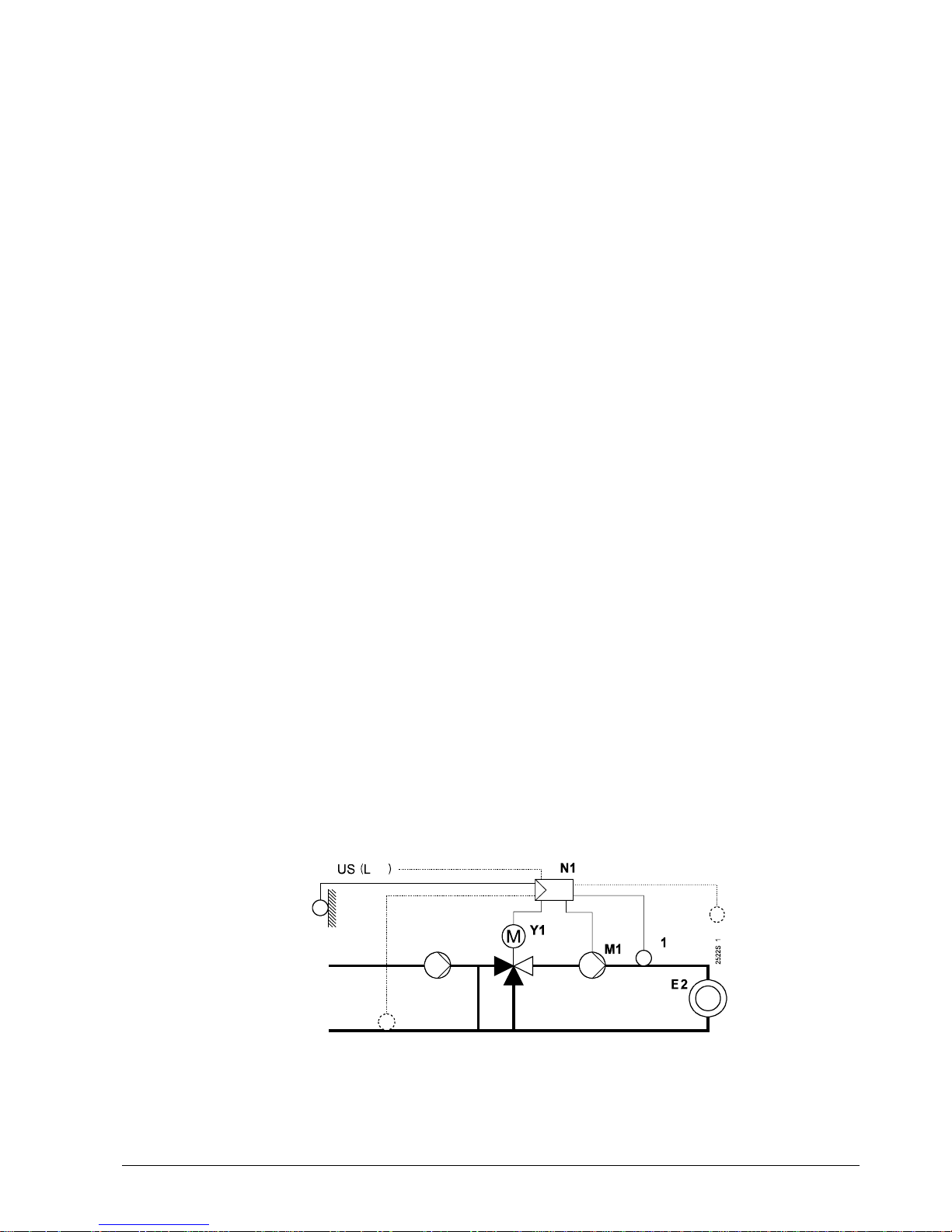
3.2.2. Plant type 2 – "Space heating with a boiler"
B9
A6/B5
Space heating with own boiler, with weather-compensated boiler temperature control.
Two-position control through a burner.
Outside temperature signal from own outside sensor or data bus. With or without room
temperature influence. Heating-up and setback according to the heating program.
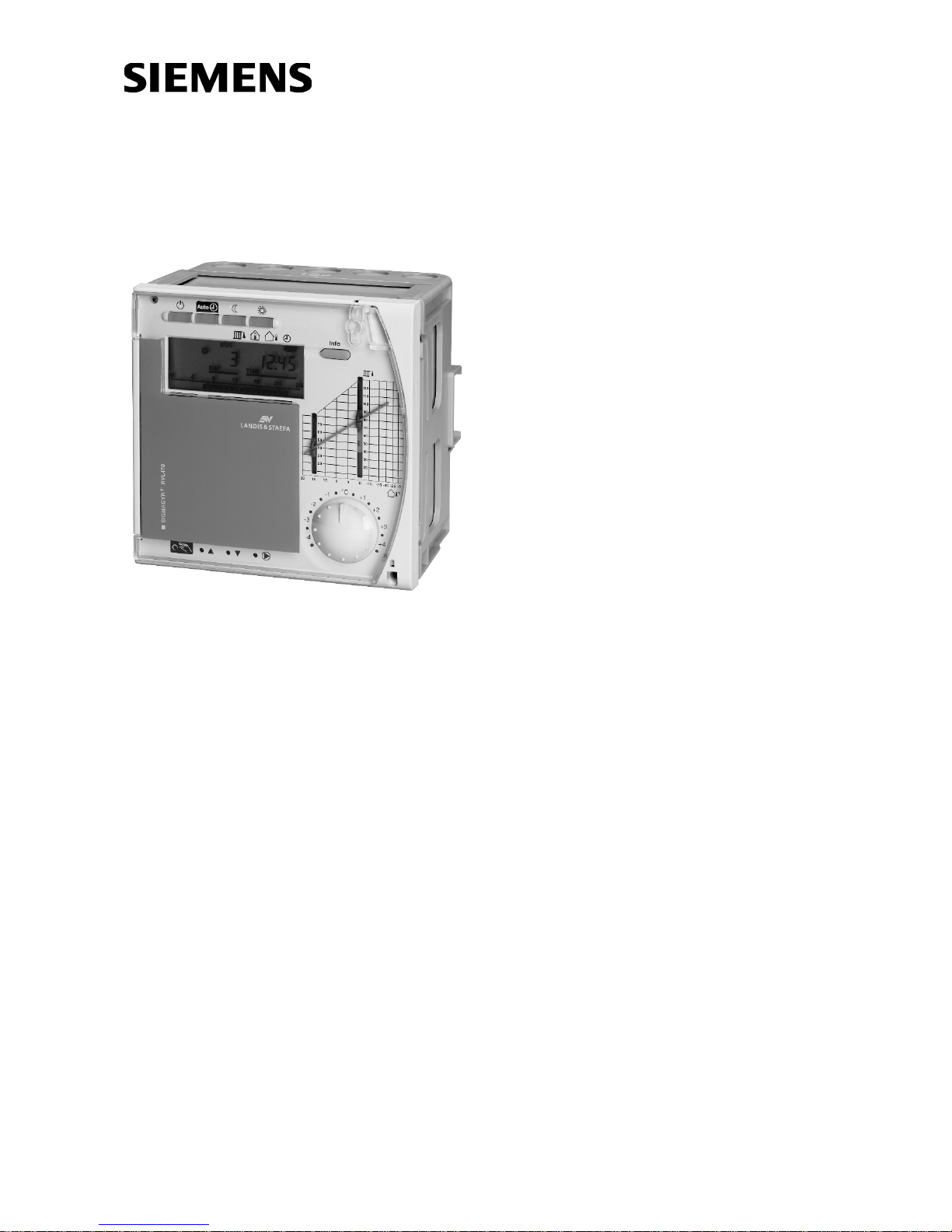
3.2.3. Plant type 3 – "Space heating with district heat"
B9
A6/B5
B7 B71
Space heating with a district heat connection, with weather-compensated flow temperature control through the valve in the primary return of the district heat connection.
Outside temperature signal from own outside sensor or data bus. With or without room
temperature influence. Heating-up and setback according to the heating program.
3.2.4. Plant type 4 – "Pre-control with a mixing valve"
B7
Pre-control with demand-compensated control of the main flow temperature. Threeposition control through the mixing valve in the main flow.
Heat demand signal from the data bus. No heating program.
Siemens Building Technologies Basic Documentation RVL470 CE1P2522E / 30.03.2000
Landis & Staefa Division
Fundamentals
7/68
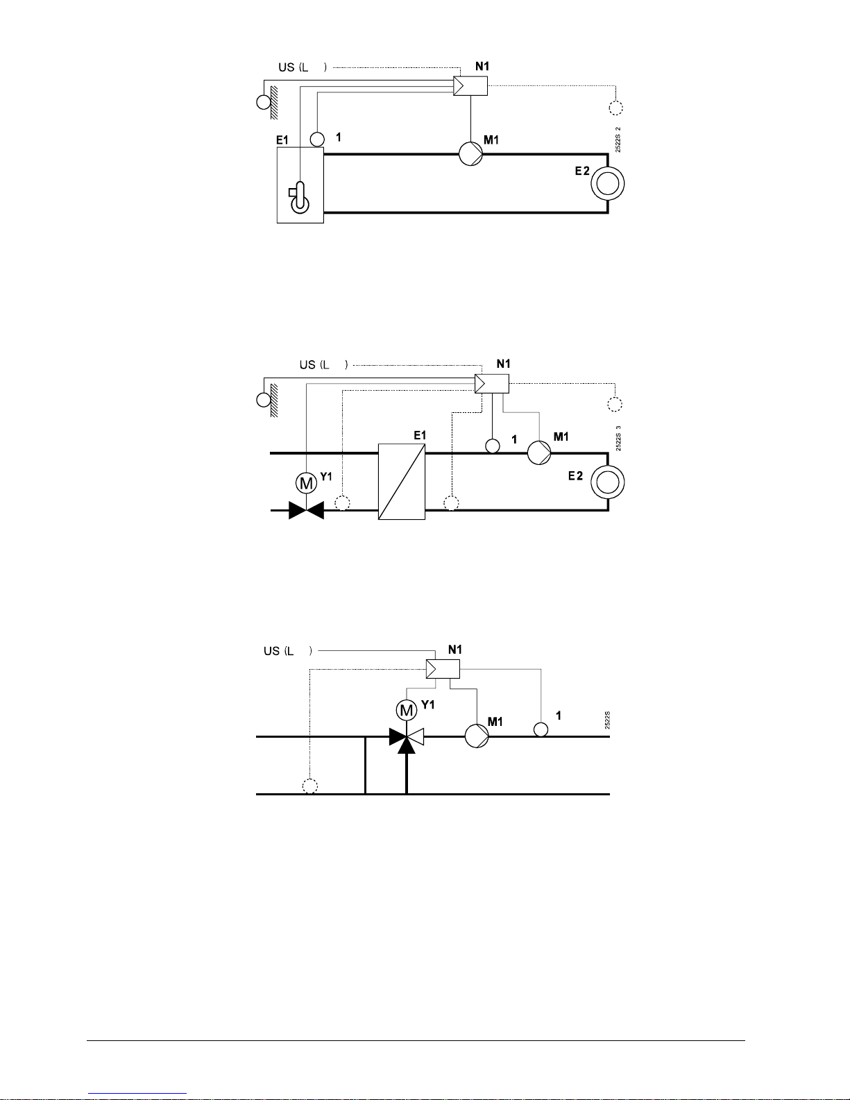
3.2.5. Plant type 5 – "Pre-control with a boiler"
B7
Pre-control with demand-compensated boiler temperature control. Two-position control
through the burner.
Heat demand signal from the data bus. No heating program.
3.2.6. Plant type 6 – "Pre-control with district heat"
B7 B71
2522S06
Pre-control with a district heat connection, with demand-compensated control of the
secondary flow temperature through the valve in the primary return.
Heat demand signal from the data bus. No heating program.
A6 Room unit QAW50 or QAW70 E1 Heat generating equipment
B1 Flow / boiler temperature sensor (boiler / heat exchanger)
B5 Room temperature sensor E2 Load (space)
B7 Return temperature sensor (primary circuit) LPB Data bus
B71 Return temperature sensor (secondary circuit) M1 Heating circuit pump/circulating pump
B9 Outside sensor N1 Controller RVL470
Y1 Heating circuit mixing valve
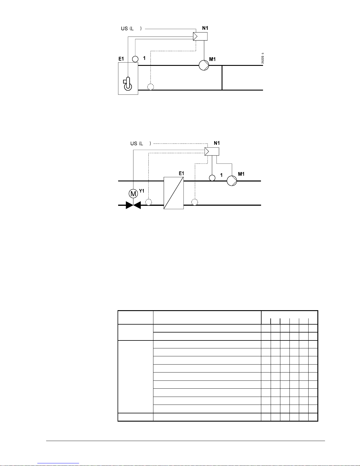
3.3. Plant types and function blocks
Plant typeLevel Function block
123456
End-user 1
zzz
End-user
level
End-user 2
zzzzzz
Plant type
zzzzzz
Space heating
zzz
Three-position actuator for heating circuit
zzzz
Boiler
zz
Setpoint of return temperature limitation
z zzzz
Settings for plant type 3
zz
Service functions and general settings
zzzzzz
Contact H2
zzzz
Heating engineer level
Contact H2 and general displays
zzzzzz
Locking level Locking functions
zzzzzz

CE1P2522E / 30.03.2000 Basic Documentation RVL470 Siemens Building Technologies
8/68
Fundamentals
Landis & Staefa Division
The block diagram shows
•
the function blocks assigned to the three operational levels
•
the function blocks activated with the different plant types
3.4. Operating modes
The operating mode is selected on the controller by pressing the respective button.
Also, the operating mode can be changed by bridging terminals H1–M.
3.4.1. Automatic mode
•
Automatic changeover from NORMAL to REDUCED temperature, and vice versa,
according to the entered weekly program
•
Automatic changeover to holiday mode, and back, according to the entered holiday
schedule
•
Demand-dependent switching of the heating system in function of the room and outside temperature while giving consideration to the building's thermal inertia (ECO
function)
•
Remote operation from a room unit (optional)
•
Frost protection is assured
3.4.2. Continuous REDUCED heating
•
Continuous heating to the REDUCED temperature
•
With ECO function
•
No holiday mode
•
Remote operation from a room unit not possible
•
Frost protection is assured
3.4.3. Continuous NORMAL heating
•
Continuous heating to NORMAL temperature
•
No ECO function
•
No holiday mode
•
Remote operation from a room unit not possible
•
Frost protection is assured
3.4.4. Standby
•
Heating is switched off, but is ready to operate
•
Frost protection is assured
3.4.5. Manual operation
The RVL470 can be switched to manual operation. In that case, the control will be
switched off.
In manual operation, the various regulating units behave as follows:
•
Heating circuit slipper valve / seat valve: this mixing valve is not under voltage, but
can be manually driven to any position by pressing the manual buttons
( = clos-
ing,
= opening).
The heating circuit pump/circulating pump M1 is continuously running.
•
Boiler: the two burner stages are continuously on. The manual button can be used
to switch the second stage on and off.
The heating circuit pump/circulating pump M1 is continuously running.
Manual operation also negates any overriding of the controller's operating mode (bridging H1–M).
Siemens Building Technologies Basic Documentation RVL470 CE1P2522E / 30.03.2000
Landis & Staefa Division
Fundamentals
9/68
3.4.6. Plant type and operating mode
Depending on the type of plant selected, the following operating modes are available:
Plant type
1 YES YES YES YES YES
2 YES YES YES YES YES
3 YES YES YES YES YES
4 YES NO NO NO YES
5 YES NO NO *) YES
6 YES NO NO NO YES
*) Depending on the boiler's operating mode:
Boiler with automatic shutdown: NO
Boiler without manual shutdown: YES
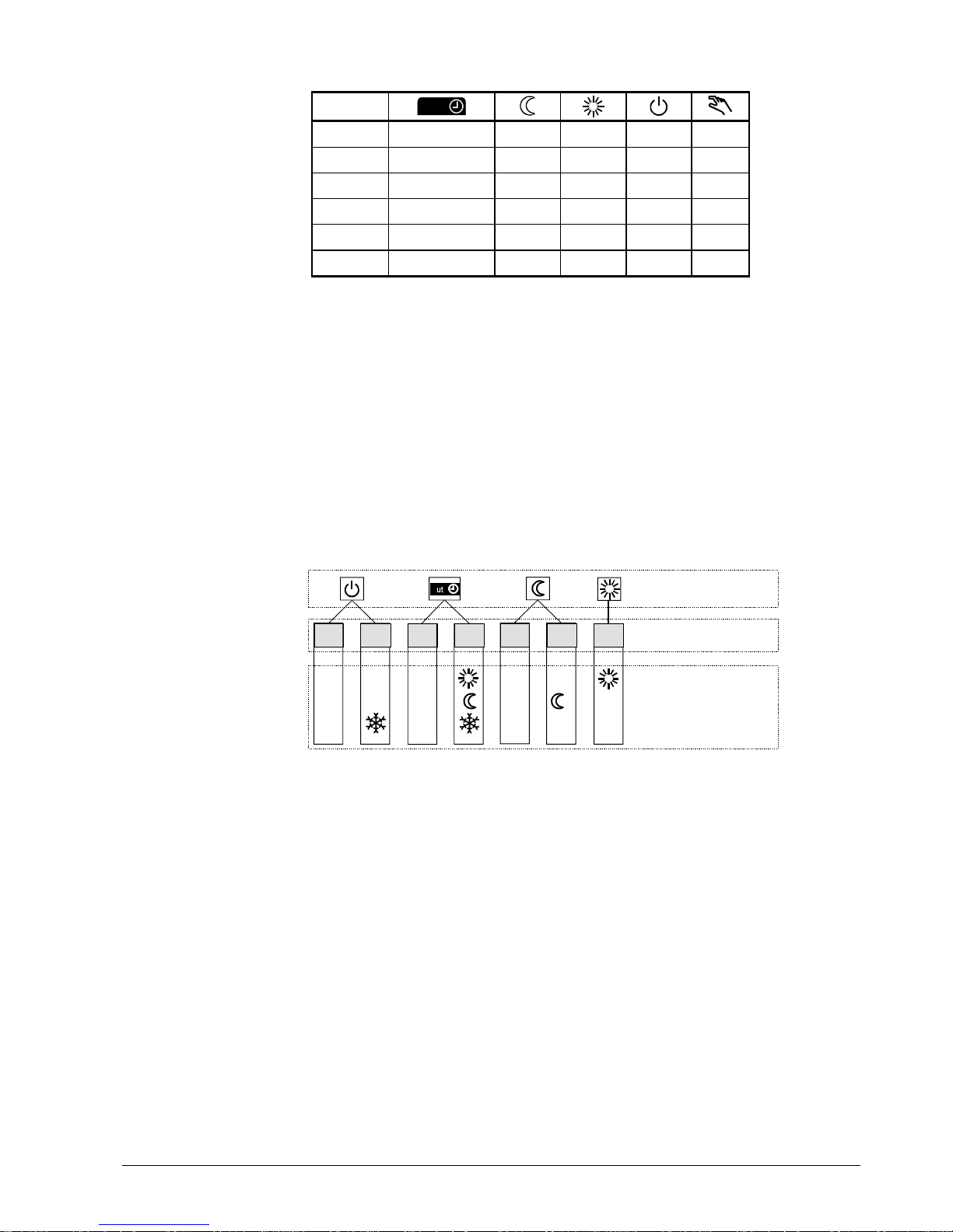
3.5. Operational status and operational level
The user selects the required operating mode by pressing the respective button. Each
operating mode has a maximum of two operational statuses – with the exception of operating mode "Continuously NORMAL heating" (only one operational status possible).
When the ECO function is activated and in the case of quick setback, the operational
status is always OFF.
When the operational status is ON, there is a maximum of three operational levels, depending on the operating mode. The operational level is determined by the heating program and the holiday program.
OFF
ON
OFF
ON
OFF ON
ON
Opera t i ng mode
Operationa l statu s
Operat ional level
2522B03e

CE1P2522E / 30.03.2000 Basic Documentation RVL470 Siemens Building Technologies
10/68
Acquisition of measured values
Landis & Staefa Division
4. Acquisition of measured values
4.1.1. Room temperature (A6, B5)
4.1.1.1. Measurement
The following choices exist:
•
A room temperature sensor QAA24 can be connected to terminal B5
•
A room unit QAW50 or QAW70 can be connected to terminal A6
•
A unit can be connected to each of the two terminals. In that case, the RVL470 can ascer-
tain the average of the two measurements.
The other room unit functions will not be affected by averaging
4.1.1.2. Handling of faults
If there is a short-circuit or an interruption in one of the two measuring circuits, the control will respond as follows:
•
No sensor (operating line 65 = 0):
A short-circuit or open-circuit has no impact on the control. A fault status message will
not be generated
•
Room unit sensor QAW... (operating line 65 = 1):
In the event of a short-circuit or open-circuit, the control continues to operate depending on the function of the room model. A fault status message will be generated
•
Room temperature sensor QAA24 (operating line 65 = 2):
In the event of a short-circuit or open-circuit, the control continues to operate depending on the function of the room model. A fault status message will be generated
•
Average value (operating line 65 = 3):
In the event of a short-circuit or open-circuit in one of the two measuring circuits, the
control continues to operate with the normally working measuring circuit. A fault
status message will be generated.
In the case of a short-circuit or open-circuit in both measuring circuits, the control
continues to operate depending on the function of the room model. Two fault status
messages will be generated
•
Automatic mode (operating line 65 = A):
Since the controller itself decides how it acquires the room temperature, no fault
status messages can be generated
4.1.1.3. Room model
The RVL470 features a room model which simulates the development of the room temperature. In plants with no measurement of the room temperature, it can provide certain
room functions (e.g. quick setback).
For more details, refer to section "8.4.4. Room model temperature".
4.1.2. Flow and boiler temperature (B1)
4.1.2.1. Measurement
The flow or boiler temperature is acquired with one or two sensors. Two sensors connected in parallel are used to ascertain the average value. The temperature sensors
used must always have a sensing element LG-Ni 1000 Ω.

Siemens Building Technologies Basic Documentation RVL470 CE1P2522E / 30.03.2000
Landis & Staefa Division
Acquisition of measured values
11/68
4.1.2.2. Handling of faults
A short-circuit or interruption in the measuring circuit is identified and displayed as a
fault. In that case, the plant will respond as follows:
•
Plants with mixing valve control:
The heating circuit pump/circulating pump M1 continues to run and the mixing valve
will close
•
Plants with boiler control:
The heating circuit pump/circulating pump M1 continues to run and the burner will
shut down
4.1.3. Outside temperature (B9)
4.1.3.1. Measurement
The outside temperature is acquired by the outside sensor, which may be a QAC22 or
QAC32:
QAC22: sensing element LG-Ni 1000 Ω at 0 °C
QAC32: sensing element NTC 575 Ω at 20 °C
The controller automatically identifies the type of sensor used. In interconnected plants,
the outside temperature signal is made available via LPB. Controllers having their own
sensor pass the outside temperature signal to the data bus.
4.1.3.2. Handling of faults
If there is a short-circuit or an interruption in the measuring circuit, the control will respond as follows:
•
In the event of a short-circuit:
If an outside temperature is made available via LPB, it is used. If none is available, the
control uses a fixed value of 0 °C outside temperature. A fault status signal is always
generated
•
In the event of an interruption:
If the controller requires an outside temperature and it is made available via LPB, it is
used. There will be no fault status signal in that case (this is the usual status in interconnected plants!). If, however, there is no outside temperature made available via
LPB, the control uses a fixed value of 0 °C. In that case, a fault status signal will be
delivered
4.1.4. Primary return temperature (B7)
4.1.4.1. Measurement
The primary return temperature is acquired with a sensor having a sensing element LGNi 1000 Ω at 0 °C. This measured value is required for minimum and maximum limitation of the primary return temperature and for limitation of the temperature differential
(DRT limitation).
In interconnected plants, the primary return temperature with plant type 1 can be acquired via the data bus. Controllers with plant type 1 and connected sensor pass the
primary return temperature signal to the data bus.
4.1.4.2. Handling of faults
If there is a short-circuit or an interruption in the measuring circuits, the control will respond as follows:
•
If, on the data bus, there is a return temperature from a controller of the same segment available, it is used (only with plant type no. 1). No fault status message will be
generated since this is the normal status in inconnected plants
•
If, on the data bus, there is no return temperature available, the return temperature
limitation functions will be deactivated and a fault status message generated

CE1P2522E / 30.03.2000 Basic Documentation RVL470 Siemens Building Technologies
12/68
Acquisition of measured values
Landis & Staefa Division
4.1.5. Secondary return temperature (B71)
4.1.5.1. Measurement
The secondary return temperature is acquired with a sensor having a sensing element
LG-Ni 1000 Ω at 0 °C. This measured value is required for limitation of the temperature
differential (DRT limitation) (plant types 3 and 6), together with the primary return temperature.
4.1.5.2. Handling of faults
If there is a short-circuit or open-circuit in the measuring circuit, and if the controller requires the return temperature, DRT limitation will be deactivated and a fault status message generated.
Siemens Building Technologies Basic Documentation RVL470 CE1P2522E / 30.03.2000
Landis & Staefa Division
Function block "End-user 1"
13/68
5. Function block "End-user 1"
This function block contains settings that the end-user himself can make.
5.1. Operating lines
Line Function, parameter Unit Factory
setting
Range
1
Setpoint for NORMAL heating °C 20.0 0...35
2
Setpoint for REDUCED heating °C 14.0 0...35
3
Setpoint for frost protection / holiday mode °C 10.0 0...35
4
Weekday 1-7 1...7, 1-7
5
1st heating period, start of NORMAL heating hh:mm 06:00 --:-- / 00:00...24:00
6
1st heating period, start of REDUCED heating hh:mm 22:00 --:-- / 00:00...24:00
7
2nd heating period, start of NORMAL heating hh:mm --:-- --:-- / 00:00...24:00
8
2nd heating period, start of REDUCED heating hh:mm --:-- --:-- / 00:00. ..24:00
9
3rd heating period, start of NORMAL heating hh:mm --:-- --:-- / 00:00...24:00
10
3rd heating period, start of REDUCED heating hh:mm --:-- --:-- / 00:00...24:00
11
Holiday period 1...8 1...8
12
Date of first day of holidays dd:MM --:-- 00.00. ... 31.12.
13
Date of last day of holidays dd:MM --:-- 00.00. ... 31.12.
14
Heating curve, flow setpoint TV1 at 15 °C outside
temperature
°C 30 20...70
15
Heating curve, flow setpoint TV2 at –5 °C outside
temperature
°C 60 20...120
5.2. Setpoints
5.2.1. General
The setpoint of the NORMAL and the REDUCED temperature and of frost protection for
the plant / holiday mode are entered directly in °C room temperature. They are independent of whether or not the control uses a room temperature sensor.
5.2.2. Frost protection for the building
The lowest valid room temperature setpoint always corresponds to at least the setpoint
of frost protection / holiday mode (setting on operating line 3), even if lower values have
been entered as the setpoints of the NORMAL and the REDUCED temperature (settings on operating lines 1 and 2).
If a room temperature sensor is used and the room temperature falls below the holiday /
frost protection setpoint, ECO – if available – will stop OFF until the room temperature
has risen 1 °C above the holiday / frost protection setpoint.
5.3. Heating program
The heating program of the RVL470 provides a maximum of three heating periods per
day. Also, every weekday may have different heating periods.
Note:
The entries to be made are not switching times, but periods of time during which the
NORMAL temperature shall apply. Usually, these periods of time are identical to the
building's occupancy times. The actual switching times for the change from the
REDUCED to the NORMAL temperature, and vice versa, are calculated by the optimization function, provided it is activated. Using the setting "1-7" on operating line 4, it is
possible to enter a heating program that applies to all days of the week. This simplifies
the settings: if the weekend settings differ from the other weekday settings, first enter

CE1P2522E / 30.03.2000 Basic Documentation RVL470 Siemens Building Technologies
14/68
Function block "End-user 1"
Landis & Staefa Division
the times for the entire week, then make the settings for days 6 and 7.
The entries are sorted and overlapping heating periods combined.
5.4. Holiday program
A maximum of eight holiday periods per year can be programmed. At 00:00 of the first
day of the holiday period, changeover to the setpoint of frost protection / holiday mode
takes place. After 24:00 of the last day of the holiday period, the RVL470 will change to
NORMAL or REDUCED mode in accordance with the time switch settings.
The settings of each holiday period will be cleared as soon as the respective period has
elapsed. The holiday periods may overlap. It is not necessary to observe a certain order.
The holiday program is only activated in AUTO mode.
Siemens Building Technologies Basic Documentation RVL470 CE1P2522E / 30.03.2000
Landis & Staefa Division
Function block "End-user 2"
15/68
6. Function block "End-user 2"
This function block contains settings that the end-user himself may make, as well as
fault indication.
6.1. Operating lines
Line Function, parameter Unit Factory
setting
Range
38
Time of day hh:mm 00:00...23:59
39
Weekday 1...7
40
Date dd:MM 1.01. ... 31.12.
41
Year yyyy 1995...2094
50
Faults 0...255
6.2. Time of day and date
The RVL470 has a yearly clock to enter the time of day, weekday and date.
The changeover from summer- to wintertime, and vice versa, is automatic. Should the
respective regulations change, the changeover dates can be adjusted (refer to
section "13. Function block "Service functions and general settings"").
6.3. Indication of faults
The following faults are indicated:
Number Fault
10 Interruption or short-circuit in the outside sensor's measuring circuit (B9)
30 Interruption or short-circuit in the flow or boiler temperature sensor's
measuring circuit (B1)
40 Interruption or short-circuit in the measuring circuit of the return tem-
perature sensor in the primary circuit (B7)
42 Interruption or short-circuit in the measuring circuit of the return tem-
perature sensor in the secondary circuit (B71)
60 Interruption or short-circuit in the room temperature sensor's measuring
circuit (B5)
61 Interruption or short-circuit in the measuring circuit of the room unit's sen-
sor (A6)
62 Wrong room unit connected
81 Short-circuit on the LPB
82 Same bus address exists on the data bus (LPB) several times
100 Two time masters on the LPB
120 Flow alarm (for explanation, refer to function block "Service functions",
operating line 171)
140 Inadmissible bus address or inadmissible plant type (if RVL470 is used
with LPB)
142 Wrong partner unit (with RVL469 only)
If a fault occurs, the LCD displays
ERROR
.
In interconnected plants, the address (device and segment number) of the controller
causing the fault is indicated on all the other controllers, but no address is displayed on
the controller causing the fault.

CE1P2522E / 30.03.2000 Basic Documentation RVL470 Siemens Building Technologies
16/68
Function block "End-user 2"
Landis & Staefa Division
Example of display in interconnected plants:
2522Z05
50
10
2
03
= line number
= error code
= device number
= segment number
The fault status signal disappears only after rectification of the fault. There will be no
acknowledgment.
Siemens Building Technologies Basic Documentation RVL470 CE1P2522E / 30.03.2000
Landis & Staefa Division
Function block "Plant type"
17/68
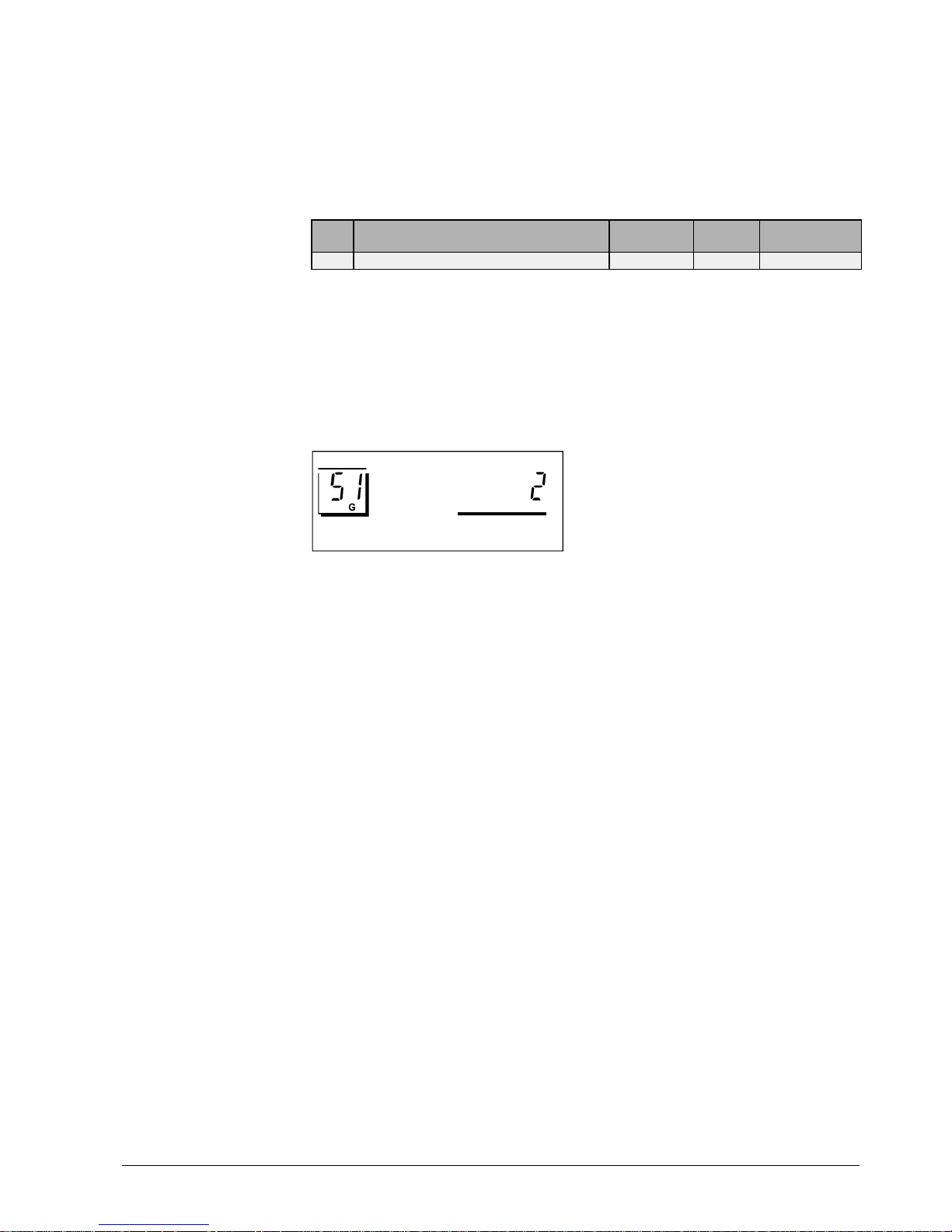
7. Function block "Plant type"
This function block only contains the entry of the type of plant.
7.1. Operating line
Line Function, parameter Unit Factory
setting
Range
51
Plant type 1 1...6
7.2. General
When commissioning the plant, the respective plant type must be entered first. This ensures that the functions required for the specific type of plant, the parameters and operating lines for the settings and displays will be activated.
All plant-specific variables and operating lines that are available for the other plant types
will then be dead.
Example (selection of plant type no. 2):
2522Z18

CE1P2522E / 30.03.2000 Basic Documentation RVL470 Siemens Building Technologies
18/68
Function block "Space heating"
Landis & Staefa Division
8. Function block "Space heating"
This function block provides the ECO function, the optimization functions with boost
heating and quick setback, as well as the room temperature influence.
8.1. Operating lines
Line Function, parameter Unit Factory
setting
Range
61
Heating limit for NORMAL heating (ECO day) °C 17.0 --.- / −5...+25
62
Heating limit for REDUCED heating (ECO night) °C 5.0 --.- / –5...+25
63
Building time constant h 20 0...50
64
Quick setback 1 0 / 1
65
Source of the room temperature A 0 / 1 / 2 / 3 / A
66
Type of optimization 0 0 / 1
67
Maximum heating-up time hh:mm 00:00 00:00...42:00
68
Maximum optimum shutdown h:mm 0:00 0:00...6:00
69
Maximum limitation of room temperature °C --.- --.- / 0...35
70
Gain factor for room temperature influence 4 0...20
71
Boost of room temperature setpoint °C 5 0...20
72
Parallel displacement of heating curve °C 0.0
−4.5...+4.5
73
Type of heating curve adjustment 0 0...2
8.2. ECO function
The ECO function controls the heating system depending on demand. It gives consideration to the development of the room temperature depending on the type of building
construction as the outside temperature varies. If the amount of heat stored in the
building is sufficient to maintain the room temperature setpoint currently required, the
ECO function will switch the heating off.
Using the ECO function, the heating system operates only, or consumes energy only
when required.
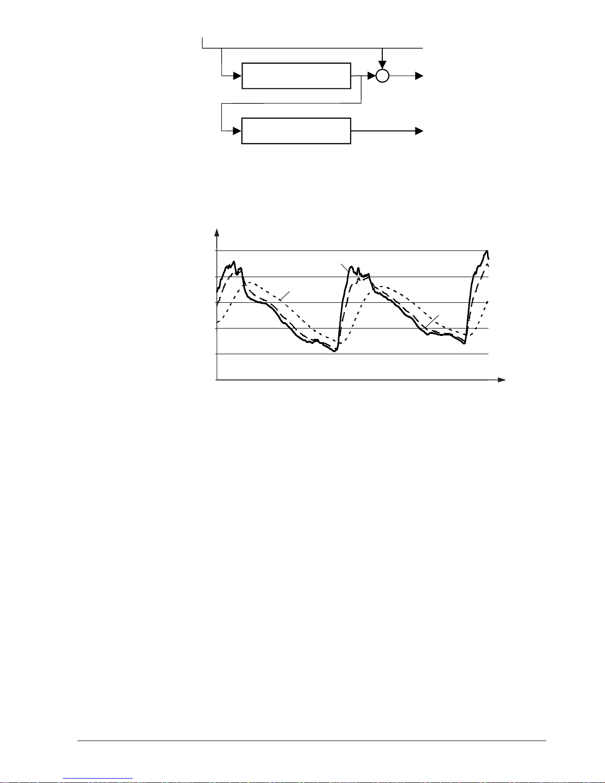
8.2.1. Compensating variables and auxiliary variables
The ECO function takes into account the development of the outside temperature and
the heat storage capacity of the building.
The following variables are taken into consideration:
•
The building time constant. This is the measure of the type of building construction
and indicates how quickly the room temperature in the building would change if the
outside temperature was suddenly changed. The following guide values can be used
for setting the building time constant: 10 hours for light, 25 hours for medium, and 50
hours for heavy building structures
•
The actual outside temperature (TA)
•
The composite outside temperature (TAM); it is the mean value of
–
the actual outside temperature and
–
the outside temperature filtered by the building time constant
In comparison with the actual outside temperature, the composite outside temperature is attenuated. Hence, it represents the effects of short-time outside temperature
variations on the room temperature as they often occur during intermediate seasons
(spring time and autumn)
•
The attenuated outside temperature (TAD). It is generated by filtering twice the actual
outside temperature by the building time constant. This means that, in comparison
with the actual outside temperature, the attenuated outside temperature is considerably dampened.
This ensures that no heating will be provided in the summer when, under normal circumstances, the heating would be switched on because the outside temperature
drops for a few days.
Siemens Building Technologies Basic Documentation RVL470 CE1P2522E / 30.03.2000
Landis & Staefa Division
Function block "Space heating"
19/68
TA (B9 or BUS)
2522B02e
T
A
k
t
k
t
T
AD
T
AM
Generation of the composite and attenuated outside temperature
TAActual outside temperature
T
AD
Attenuated outside temperature
T
AM
Composite outside temperature
kt Building time constant
0
5
10
15
20
25
T
AD
T
AM
t
2522D17
T
A
T
A
Development of the actual, composite and attenuated outside temperature
TAActual outside temperature
T
AD
Attenuated outside temperature
T
AM
Composite outside temperature
tTime
8.2.2. Heating limits
Two heating limits can be set:
•
"ECO day" for NORMAL heating
•
"ECO night" for the lower temperature level; this may be REDUCED heating or OFF
(holidays / frost protection)
In both cases, the heating limit is the outside temperature at which the heating shall be
switched on and off. The switching differential is 1 °C.
8.2.3. Mode of operation
8.2.3.1. Switching the heating off
The heating will be switched off when
one
of the three following conditions is satisfied:
•
The actual outside temperature exceeds the current ECO heating limit
•
The composite outside temperature exceeds the current ECO heating limit
•
The attenuated outside temperature exceeds the "ECO day" heating limit
In all these cases, it is assumed that the amount of heat entering the building envelope
from outside or the amount of heat stored in the building structure will be sufficient to
maintain the required room temperature level.
When the ECO function has switched the heating off, the display shows
ECO
.

CE1P2522E / 30.03.2000 Basic Documentation RVL470 Siemens Building Technologies
20/68
Function block "Space heating"
Landis & Staefa Division
8.2.3.2. Switching the heating on
The heating will be switched on again only when
all
three of the following conditions are
satisfied:
•
The a c t ual o u t s i d e temperature has fallen 1 °C below the current ECO heating limit
•
The composite outside temperature has fallen 1 °C below the current ECO heating
limit
•
The attenuated outside temperature has fallen 1 °C below the "ECO day" heating limit
8.2.4. Operating modes and operational statuses
The ECO function is provided depending on the operating mode:
Operating mode or operational status ECO function Actual heating limit
Automatic mode Active ECO day or ECO night
Continuously REDUCED heating Active ECO night
Continuously NORMAL heating Inactive –
STANDBY Active ECO-night
Frost protection / holiday mode Active ECO-night
Manual operation Inactive –
8.3. Room temperature source
The room temperature source can be selected on operating line 65.
The following settings are possible:
Operating line 65 Room temperature source
0 No room temperature sensor
1 Room unit connected to terminal A6
2 Room temperature sensor connected to terminal B5
3 Average value of devices connected to terminals A6 and B5
A Automatic selection
Line 65 also displays the room temperature source effectively used by the controller
(indicated by ACTUAL):
ACTUAL = 0 Controller uses no sensor
ACTUAL = 1 Controller uses the room unit connected to terminal A6
ACTUAL = 2 Controller uses the room temperature sensor connected to
terminal B5
ACTUAL = 3 Controller operates with the average value delivered by the devices
connected to terminals A6 and B5
8.4. Optimization
8.4.1. Definition and purpose
Operation is optimized. EN 12098 defines optimization as "automatic shifting of the
switch-on and switch-off points aimed at saving energy". This means that
•
switching on and heating up as well as switching off are controlled such that during
building occupancy times the required room temperature level will always be ensured
•
the smallest possible amounts of energy will be used to achieve this objective

Siemens Building Technologies Basic Documentation RVL470 CE1P2522E / 30.03.2000
Landis & Staefa Division
Function block "Space heating"
21/68
8.4.2. Fundamentals
It is possible to select or set:
•
The type of optimization: either with a room temperature sensor/room unit or based on
the room model
•
The maximum limit value for the heating-up time
•
The maximum limit value for optimum shutdown
•
Quick setback: yes or no
To perform the optimization function, the controller makes use of the actual room temperature – acquired by a room temperature sensor or room unit – or the room model.
8.4.2.1. With a room temperature sensor
Using a room temperature sensor or room unit, it is possible to have optimum start control
and
optimum stop control. To be able to optimally determine the switch-on and
switch-off points, optimization needs to "know" the building's heating up and cooling
down characteristics, always in function of the prevailing outside temperature. For this
purpose, optimization continually acquires the room temperature and the respective
outside temperature. It captures these variables via the room temperature sensor and
the outside sensor and continually adjusts the forward shift of the switching points. In
this way, optimization can also detect changes made to the building and to take them
into consideration.
The learning process always concentrates on the first heating period per day.
8.4.2.2. Without a room temperature sensor
When no room temperature sensor is used, the room model
only
allows optimum start
control.
Optimization operates with fixed values (no learning process), based on the set maximum heating up time and the room model.
8.4.3. Process
HP
T
Rw
T
Rx
T
Rw
T
Rw
T
Rw
Hp Heating program T
Rw
Room temperature setpoint of NORMAL heating
tTime T
Rw
Room temperature setpoint of REDUCED heating
t1 Forward shift for early shutdown
∆
T
Rw
Setpoint boost (only with boost heating)
t2 Forward shift for start of heating-up T
Rx
Actual value
t3 Quick setback TR Room temperature
T
Rw
Setpoint
8.4.4. Room model temperature
To ascertain the room temperature generated by the room model, a distinction must be
made between two cases:

CE1P2522E / 30.03.2000 Basic Documentation RVL470 Siemens Building Technologies
22/68
Function block "Space heating"
Landis & Staefa Division
•
The RVL470 is not in quick setback mode:
The room temperature generated by the room model is identical to the actual room
temperature setpoint
•
The RVL470 is in setback mode:
The room temperature generated by the room model is determined according to the
following formula:
t
3 * kt
Room model temperature TRM [°C] = (TRw – TAM ) * e
Development of the room temperature as generated by the room model
2522D18
t
1
T
Rw
T
RM
T
Rw
T
Rw
e 2.1828 (basis of natural logarithms)
k
t
Building time constant in hours
t Time in hours
t
1
Quick setback
T
AM
Composite outside temperature
T
R
Room temperature
T
RM
Room model temperature
T
Rw
Setpoint of the normal room temperature
T
Rw
Setpoint of the reduced room temperature
8.4.5. Optimum stop control
During the building’s occupancy times, the RVL470 maintains the setpoint of NORMAL
heating. Toward the end of the occupancy time, the control switches to the REDUCED
setpoint. Optimization calculates the changeover time such that, at the end of occupancy, the room temperature will be 0.5 °C below the setpoint of NORMAL heating (optimum shutdown).
By entering 0 hours as the maximum optimum shutdown, optimum stop control can be
deactivated.
8.4.6. Quick setback
When changing from the NORMAL temperature to a lower temperature level
(REDUCED or holidays / frost), the heating will be shut down. And it will remain shut
down until the setpoint of the lower temperature level is reached.
•
When using a room temperature sensor, the effective actual value of the room temperature is taken into account
•
When using no room temperature sensor, the actual value is simulated by the room
model
The duration of quick setback is determined according to the following formula:
T
Rw
– T
AM
t [ h ] = 3 * kt * ( – ln
––––––––––– )
T
Rw
– T
AM

Siemens Building Technologies Basic Documentation RVL470 CE1P2522E / 30.03.2000
Landis & Staefa Division
Function block "Space heating"
23/68
where:
ln Natural logarithm
kt Building time constant in hours
t Duration of setback
TAM Composite outside temperature
TRw
Setpoint of the NORMAL room temperature
TRw
Setpoint of the REDUCED room temperature
8.4.7. Optimum start control
During the building’s non-occupancy times, the RVL470 maintains the setpoint of
REDUCED heating. Toward the end of the non-occupancy time, optimization switches
the control to boost heating. This means that the selected boost will be added to the
room temperature setpoint. Optimization calculates the changeover time such that, at
the start of occupancy, the room temperature will reach the setpoint of NORMAL heating.
When the room temperature is simulated by the room model, that is, when using no
room temperature sensor, the forward shift in time is calculated as follows:
t [ min ] = ( T
Rw
– TRM ) * 60
where:
tForward shift
TRw
Setpoint of the NORMAL room temperature
T
RM
Room model temperature
Optimum start control with the room model takes place only if a quick setback was previously effected.
Optimum start control can be deactivated by entering 0 hours as the maximum heatingup period.
8.4.8. Boost heating
For boost heating, a room temperature setpoint boost can be set. After changeover to
the NORMAL temperature, the higher room temperature setpoint applies, resulting in an
appropriately higher flow temperature setpoint.
t
2522D08
T
R
T
Rw
T
Rx
T
Rw
T
Rw
T
Rw
tTime
T
R
Room temperature
T
Rw
Setpoint of NORMAL room temperature
T
Rw
Setpoint of REDUCED room temperature
T
Rx
Actual value of the room temperature
T
Rw
Room temperature setpoint
∆
T
Rw
Boost of room temperature setpoint (with boost heating)
Duration of boost:
•
When using a room sensor, boost heating is maintained until the room temperature
has reached the setpoint of normal heating. Then, that setpoint is used again

CE1P2522E / 30.03.2000 Basic Documentation RVL470 Siemens Building Technologies
24/68
Function block "Space heating"
Landis & Staefa Division
•
When using no room sensor, the room model calculates how long boost heating will
be maintained. The duration is determined according to the following formula:
T
Rw
– T
RM1
k
t
t1 [ h ] = 2
*
––––––––––––
*
––––
T
Rw
– T
Rw
20
The duration of the boost is limited to two hours.
t
2522D19
T
RM
T
R
t
1
T
RM1
T
Rw
T
Rw
T
Rw
T
Rw
k
t
Building time constant in hours
tTime
t
1
Duration of room temperature setpoint boost (with boost heating)
T
R
Room temperature
T
Rw
Setpoint of the NORMAL room temperature
T
Rw
Setpoint of the REDUCED room temperature
T
RM
Room model temperature
T
RM1
Room model temperature at the start of boost heating
T
Rw
Room temperature setpoint
∆
T
Rw
Boost of room temperature setpoint (with boost heating)
8.5. Room functions
8.5.1. Maximum limitation of the room temperature
For the room temperature, it is possible to have an adjustable maximum limitation, in
which case a room temperature sensor is required (sensor or room unit). If the room
temperature lies 1 °C above the limit value, the room temperature setpoint will be lowered by 4 °C.
Maximum limitation of the room temperature is independent of the setting used for the
room temperature influence.
If the room temperature lies above the limit value, the display shows
.
The reduction of the flow temperature setpoint ∆T
Vw
is calculated as follows:
∆
T
Vw
[K] = ∆TRw * ( 1 + s )
-1
-0,5 0,5 1 1,5 2 2,5 3
T
Rw
T
R
s Heating curve slope
∆
T
Rw
Reduction of room temperature setpoint
∆
T
R
Deviation of room temperature from the limit value (actual value / limit value)
∆
T
Vw
Reduction of flow temperature setpoint

Siemens Building Technologies Basic Documentation RVL470 CE1P2522E / 30.03.2000
Landis & Staefa Division
Function block "Space heating"
25/68
8.5.2. Room temperature influence
The room temperature is included in the control process, in which case a room temperature sensor is required (sensor or room unit).
The gain factor for the room temperature influence can be adjusted. This indicates to
what extent deviations of the actual room temperature from the setpoint have an impact
on flow temperature control:
0 = room temperature deviations have no impact on the generation of the setpoint
20 = room temperature deviations have a maximum impact on the generation of the
setpoint
The reduction of the room temperature setpoint ∆T
Rw
is calculated according to the fol-
lowing formula:
VF
∆
T
Rw
[K] = –––––
*
( TRw – TRx )
2
T
Rw
T
R
T
Rw
The change of the flow temperature setpoint resulting from the change of the room temperature setpoint is calculated as follows:
∆
T
Vw
[K] = ∆TRw * ( 1 + s )
where:
s Heating curve slope
T
Rw
Room temperature setpoint
∆
T
Rw
Change of room temperature setpoint
-∆T
Rw
Reduction of room temperature setpoint
+∆T
Rw
Increase of room temperature setpoint
T
Rx
Actual value of room temperature
∆
T
R
Room temperature deviation (T
Rw
–
TRx)
∆
T
Vw
Change of flow temperature setpoint
VF Gain factor
8.6. Heating curve
8.6.1. Purpose
With the space heating systems (plant types 1, 2 and 3), flow temperature control is
always weather-compensated. Assignment of the flow temperature setpoint to the prevailing outside temperature is made via the heating curve.
8.6.2. Basic setting
The basic setting of the heating curve is made with the little bar or via two operating
lines (also refer to section "19.1.2. Analog operating elements").
The following settings are required:
•
The flow temperature setpoint at –5 °C outside temperature
•
The flow temperature setpoint at +15 °C outside temperature
The basic setting during commissioning is made according to the planning documentation or in agreement with local practices.

CE1P2522E / 30.03.2000 Basic Documentation RVL470 Siemens Building Technologies
26/68
Function block "Space heating"
Landis & Staefa Division
8.6.2.1. Settings with the bar
2522Z11
8.6.2.2. Settings on operating lines
The settings are made on operating lines 14 and 15:
Line Setpoint
14 TV1, flow temperature setpoint at an outside temperature of +15 °C
15 TV2, flow temperature setpoint at an outside temperature of –5 °C
8.6.2.3. Selection of setting
The kind of setting can be selected on operating line 73:
Line 73 Bar Line 14 Line 15
0 Active Inactive Inactive
1 Inactive Active Active
2 Inactive Display function only, read-
justment only via LPB
Display function only, readjustment only via LPB
8.6.3. Deflection
The heat losses of a building are proportional to the difference between room temperature and outside temperature. By contrast, the heat output of radiators does not increase proportionally when the difference between radiator and room temperature increases.
For this reason, the radiators' heat exchanger characteristic is deflected. The heating
curve's deflection takes these properties into consideration.
In the range of small slopes (e.g. with underfloor heating systems), the heating curve is
practically linear – due to the small flow temperature range – and therefore corresponds
to the characteristic of low temperature heating systems.
The slope s is determined according to the following formula:
T
Vw(–5)
− T
Vw(+15)
s [–] = ––––––––––––––
20 K
where:
s Heating curve slope
T
Vw(–5)
Flow temperature setpoint at an outside temperature of –5 °C
T
Vw(+15)
Flow temperature setpoint at an outside temperature of +15 °C
On the controller, the heating curve is set as a straight line, but the straight line corresponds exactly to the deflected heating curve, because a non-linear outside temperature scale corresponds to the deflection.
The heating curve is valid for a room temperature setpoint of 20 °C.

Siemens Building Technologies Basic Documentation RVL470 CE1P2522E / 30.03.2000
Landis & Staefa Division
Function block "Space heating"
27/68
8.6.4. Parallel displacement of heating curve
The heating curve can be displaced parallel:
•
Manually with the setting knob for room temperature readjustments. The readjustment
can be made by the end-user and covers a maximum range of –4.5...+4.5 °C room
temperature
•
Manually on operating line 72
This parallel displacement of the heating curve is calculated as follows:
Parallel displacement ∆T
Flow
= ( ∆T
Knob
+ ∆T
Operating line 72
)
*
( 1 + s )
Parallel displacement of the heating curve
20
10 0 -10 -20
-30
90
80
70
60
50
40
30
2522D10
100
0
10
10
0
30
T
Rw
T
A
T
V
s Slope
T
A
Outside temperature
T
V
Flow temperature
T
WR
Room temperature setpoint
8.6.5. Display of setpoints
Two setpoints result from the basic setting, the position of the setting knob and – if
made – the entry on operating line 72, which can be called up on operating line 166:
•
TV1, resulting flow temperature setpoint at an outside temperature of +15 °C
•
TV2, resulting flow temperature setpoint at an outside temperature of –5 °C
These two current setpoints determine the actual heating curve from which – in function
of the composite outside temperature – the current flow temperature setpoint is generated. It can be called up on operating line 165 (also refer to section "13. Function block
"Service functions and general settings"").

CE1P2522E / 30.03.2000 Basic Documentation RVL470 Siemens Building Technologies
28/68
Function block "Space heating"
Landis & Staefa Division
8.7. Generation of setpoint
8.7.1. Weather-compensated control
Weather-compensated control is used with plant types 1, 2 and 3.
The setpoint can be generated in two different ways:
•
In function of the outside temperature via the heating curve (for setting, refer to section "8.6. Heating curve"). The temperature used is the
composite
outside tempera-
ture
•
Manual preselection of a constant setpoint. This is accomplished by bridging terminals
H2–M. It is possible to choose whether the setpoint shall be absolute or used as a
minimum limit value (refer to section "13. Function block "Service functions and general settings"")
Composite outside
temperature
Setting knob
room unit *
Heating curve
Setting knob
on controller
Flow temperature
setpoint T
Vw
Setpoint on
operating line 165
Parallel displacement of
heating curve, operating line 72
LPB
SYNERGYR
OZW30
Room setpoint
or
s
1 + s
20 °C
Operating line
1, 2 oder 3
1 + s
2524B01e
LPB Data bus
OZW30 SYNERGYR central unit
s Slope
* Active only with room unit level
The impact of the central unit OZW30 is described in section "17.1.4. Combination with
SYNERGYR central unit OZW30".
8.7.2. Demand-compensated control
Demand-compensated control is used with plant types 4, 5 and 6. The setpoint is delivered to the RVL470 via LPB in the form of a heat demand signal. In that case, the outside temperature will not be taken into consideration.
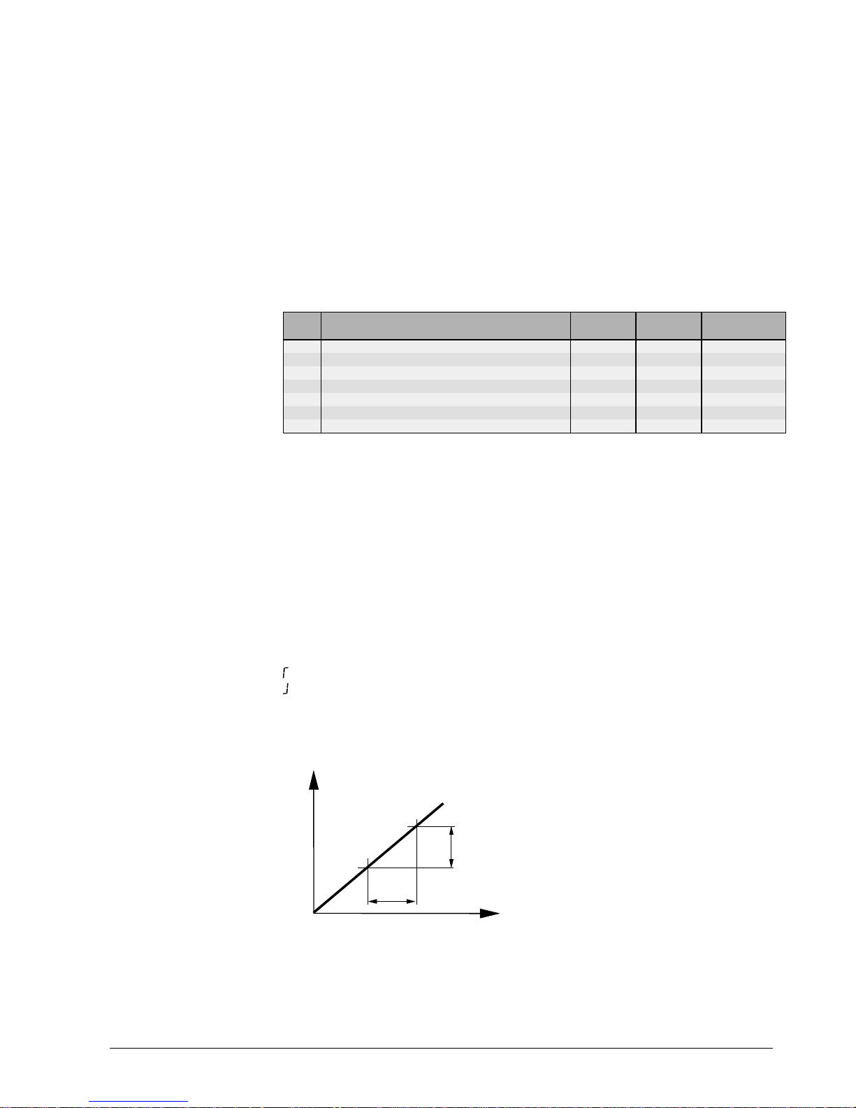
Siemens Building Technologies Basic Documentation RVL470 CE1P2522E / 30.03.2000
Landis & Staefa Division
Function block "Three-position actuator heating circuit"
29/68
9. Function block "Three-position actuator heating circuit"
This function block provides three-position control. Depending on the type of plant, it
acts as follows:
•
Weather-compensated, on the mixing valve of a space heating system
(plant type 1)
•
Weather-compensated, on the valve in the primary return of a space heating
system with a district heat connection (plant type 3)
•
Demand-compensated, on the mixing valve of a main flow (plant type 4)
•
Demand-compensated, on the valve in the primary return of a main flow with a district
heat connection (plant type 6)
9.1. Operating lines
Line Function, parameter Unit Factory
setting
Range
81
Maximum limitation of flow temperature °C --- --- / 0...140
82
Minimum limitation of flow temperature °C --- --- / 0...140
83
Maximum rate of flow temperature increase °C/h --- --- / 1...600
84
Excess temperature mixing valve / heat exchanger °C 10 0...50
85
Actuator running time s 120 30...873
86
P-band of control (Xp) °C 32.0 1...100
87
Integral action time of control (Tn) s 120 30...873
9.2. Limitations
9.2.1. Limitations of the flow temperature
The following limitations can be set:
•
Maximum limitation of flow temperature: at the limit value, the heating curve runs hori-
zontal. This means that the flow temperature setpoint cannot exceed the maximum
value
•
Minimum limitation of flow temperature: at the limit value, the heating curve runs hori-
zontal. This means that the flow temperature setpoint cannot fall below the minimum
value
If the setpoint is limited, the display shows:
= for maximum limitation
= for minimum limitation
Both limitations can be deactivated (setting
---
).
9.2.2. Setpoint increase
t
t
2522D07
T
Vw
T
Vw
Maximum slope =
∆
T
Vw
––––––
∆
t
tTime
∆
t Unit of time
T
Vw
Flow temperature setpoint
∆
T
Vw
Setpoint rise per unit of time

CE1P2522E / 30.03.2000 Basic Documentation RVL470 Siemens Building Technologies
30/68
Function block "Three-position actuator heating circuit"
Landis & Staefa Division
The rate of increase of the flow temperature setpoint can be limited to a maximum. In
that case, the maximum rate of increase of the flow temperature setpoint is the selected
temperature per unit of time (°C per hour).
This function
•
prevents cracking noise in the piping
•
protects objects and construction materials that are sensitive to quick temperature
increases (e.g. antiquities)
•
prevents excessive loads on heat generating equipment
This function can be deactivated (setting
---
).
9.3. Three-position control
Three-position control operates as weather- or demand-compensated PI flow temperature control. The flow temperature is controlled through the modulating regulating unit
(slipper or seat valve). Thanks to the I-part, there is no control offset.
The control's positioning commands to the actuator of the regulating unit are fed to the
output relays and indicated by LEDs.
9.4. Excess mixing valve temperature
In interconnected plants, an excess mixing valve temperature can be entered on the
RVL470. This is a boost of the heating zone's flow temperature setpoint. The higher
setpoint is delivered to the heat generating equipment as the heat demand signal.
The excess mixing valve temperature can only be set on controllers driving a mixing
valve (controller N2 in the example below, operating line 84).
Example:
N2
w
N2
w
N1
= wN2 + w
2522S07
w
N1 Boiler temperature controller (heat generation)
N2 Flow temperature controller (heating zone)
w
N1
Setpoint of the boiler temperature controller
w
N2
Setpoint of the flow temperature controller
∆
w Excess mixing valve temperature (to be set on controller N2)
9.5. Locking of pulses
If the actuator receives only closing or opening pulses for a period of time equivalent to
five times the actuator running time, all additional pulses delivered by the controller will
be locked, thus reducing the strain on the actuator.
For safety reasons however, the controller delivers pulse in the opposite direction at 10minute intervals.
An pulse in the opposite direction negates the pulse lock.

Siemens Building Technologies Basic Documentation RVL470 CE1P2522E / 30.03.2000
Landis & Staefa Division
Function block "Boiler"
31/68
10. Function block "Boiler"
Function block "Boiler" acts as a two-position controller and is used for direct burner
control. Depending on the type of plant, it acts as a
•
boiler temperature controller for weather-compensated control of a space heating
system (plant type 2)
•
boiler temperature controller for demand-compensated control of a main flow (plant
type 5)
10.1. Operating lines
Line Function, parameter Unit Factory
setting
Range
91
Operating mode of boiler 0 0 / 1
92
Maximum limitation of boiler temperature °C 95 25...140
93
Minimum limitation of boiler temperature °C 10 5...140
94
Switching differential °C 6 1...20
95
Minimum burner running time min 4 0...10
96
Release limit for second burner stage °C*min 50 0...500
97
Reset limit for second burner stage °C*min 10 0...500
98
Waiting time second burner stage min 20 0...40
99
Operating mode pump M1 1 0 / 1
10.2. Operating mode
When there is no demand for heat (e.g. due to the ECO function), three different boiler
operating modes are available:
•
With manual shutdown: the boiler will be shut down when there is no demand for heat
and operating mode standby
is selected (setting 0 on operating line 91)
•
With automatic shutdown: the boiler will be shut down when there is no demand for
heat, irrespective of the selected operating mode (setting 1 on operating line 91)
Boiler operating modes, when there is no demand for heat:
Boiler operating modeController's operat-
ing mode With manual shutdown With automatic shutdown
Stand-by Boiler OFF Boiler OFF
AUTO Boiler at min. limit value Boiler OFF
REDUCED Boiler at min. limit value Boiler OFF
NORMAL Boiler at min. limit value Boiler OFF
With plant type 5, it is not possible to select all operating modes (refer to section "3.4.
Operating modes").
When there is demand for heat, the boiler always supplies heat, which means that the
boiler's operating mode will always be ON.
10.3. Limitations
10.3.1. Maximum limitation of the boiler temperature
For maximum limitation of the boiler temperature, the maximum limit value can be adjusted. The switch-off point cannot exceed the maximum limit value. The switch-on point
will then be lower by the amount of the set switching differential.
If the boiler temperature is limited, the display shows:
= for maximum limitation
= for minimum limitation
These limitations cannot be used as safety functions. For that purpose, thermostats,
thermal reset limit thermostats, etc., must be used.

CE1P2522E / 30.03.2000 Basic Documentation RVL470 Siemens Building Technologies
32/68
Function block "Boiler"
Landis & Staefa Division
10.3.2. Minimum limitation of the boiler return temperature
For minimum limitation of the boiler temperature, a minimum limit value can be adjusted.
The switch-on point cannot fall below the minimum limit value. The switch-off point will
then be higher by the amount of the set switching differential.
If the return temperature is limited, the display shows
.
10.4. Two-position control
Two-position control controls the boiler temperature by switching a single- or two-stage
burner on and off.
The control's commands to the burner or burner stages are fed to the output relays and
indicated by LEDs.
10.4.1. Control with a single-stage burner
For two-position control with a single-stage burner, the variables that can be set are the
switching differential and the minimum burner running time.
The controller compares the actual value of the boiler temperature with the setpoint. If
the boiler temperature falls below the setpoint by half the switching differential, the
burner will be switched on. If the boiler temperature exceeds the setpoint by half the
switching differential, the burner will be switched off.
T
K
2522D16
ON
OFF
T
Kw
SD2SD
2
SD
T
K
T
Kw
Switching differential
Boiler temperature
Boiler temperature setpoint
If there is no more deviation before the minimum burner running time has elapsed, the
burner will nevertheless remain activated until that time is completed (burner cycling
protection). This means that the minimum burner running time has priority, provided the
boiler temperature will not exceed the maximum limit, which will always lead to burner
shutdown.
TKw + 0,5
*
SD
0
1
2522D14
T
K
T
Kw
TKw - 0,5
*
SD
T
Kx
t
Y
B
SD Switching differential
tTime
T
K
Boiler temperature
w
TK
Boiler temperature setpoint
x
TK
Actual value of the boiler temperature
Y
B
Burner control signal
Note: when controlling a single-stage burner, the reset limit of the second stage should
be set to zero.

Siemens Building Technologies Basic Documentation RVL470 CE1P2522E / 30.03.2000
Landis & Staefa Division
Function block "Boiler"
33/68
10.4.2. Control with a two-stage burner
10.4.2.1. Setting parameters
For two-position control with a two-stage burner, the variables that can be set are the
switching differential and the minimum burner running time – which now apply to both
stages – plus the following variables:
•
The release limit (FGI) for the second stage. This is the variable generated from the
temperature (T) and the time (t). If the maximum limit is exceeded, the second burner
stage is released and can switch on, provided the minimum waiting time for the second stage has elapsed
FGI =
∆
Tdt
t
0
∫
where:
∆
T
= ( w − 0.5 * SD − x ) > 0
•
The reset limit (RSI). This is the variable generated from the temperature (T) and the
time (t). If the maximum limit is exceeded, the burner will be locked and switches off
RSI =
∆
Tdt
t
0
∫
where:
∆
T
= ( x − w + 0.5 * SD ) > 0
•
The minimum locking time for the second stage, that is, the period of time on completion of which the second stage can switch on at the earliest
10.4.2.2. Control
The controller compares the actual value of the flow temperature with the flow temperature setpoint. If it falls below the setpoint by half the switching differential
(x < w – 0.5
*
SD), the first burner stage will be switched on. At the same time, the minimum waiting time for the second burner stage is started and the release limit (integral)
is being generated. The controller ascertains for how long and by how much the flow
temperature remains below w – 0.5
*
SD. It continually generates the release limit based
on the time and the temperature.
If, on completion of the minimum locking time, the flow temperature lies below
w – 0.5
*
SD, and if the release limit reaches the set maximum limit, the second burner
stage will be released and switched on. The flow temperature starts rising.
When the flow temperature has exceeded the setpoint by half the switching differential
(x = w + 0.5
*
SD), the second burner stage is switched off again, but will remain released. The first stage continues to operate. If the flow temperature drops, the second
stage will be switched on again at x < w – 0.5
*
SD. The setpoint is now maintained by
the second burner stage.
If, however, the flow temperature continues to rise (x > w + 0.5
*
SD), the controller
starts generating the reset limit (integral). It determines for how long and to what extent
the flow temperature stays above the setpoint by half the switching differential. It continually generates the reset limit based on the time and the temperature. When the reset
limit reaches the set maximum limit, the second burner stage will be locked and the first
stage switched off.
The minimum waiting time and the calculation of the release limit at x < w – 0.5
*
SD are
started when the switch-on command for the first burner stage is given.
Due to the time-temperature integral, it is not only the duration of the deviation that is
considered, but also its extent, when deciding whether the second stage shall be
switched on or off.
SD Switching differential
w Boiler temperature setpoint
x Actual value of boiler temperature

CE1P2522E / 30.03.2000 Basic Documentation RVL470 Siemens Building Technologies
34/68
Function block "Boiler"
Landis & Staefa Division
1
0
INT
max.
FG
B2
1
0
Y
B2
t
FGI
RSI
2522D09
0
1
0
t
t
t
t
Y
B1
max.
TKw + 0,5
*
SD
T
Kw
- 0,5
*
SD
T
Kx
RSI
FGB2Release of burner stage 2 t Time
FGI Release limit T
Kw
Boiler temperature setpoint
INT Integral T
Kx
Actual value of the boiler temperature
RSI Reset limit Y
B1
Control signal for burner stage 1
SD Switching differential Y
B2
Control signal for burner stage 2
10.4.3. Frost protection for the boiler
Frost protection for the boiler uses fixed values:
•
Switch-on point: 5 °C boiler temperature
•
Switch-off point: minimum limit of boiler temperature plus switching differential
If the boiler temperature falls below 5 °C, the burner will always be switched on until the
boiler temperature has crossed the minimum limit by the amount of the switching differential.
10.4.4. Protective boiler startup
If, while the burner is running, the boiler temperature falls below the minimum limit of the
boiler temperature, the differential (minimum limit value minus actual value) will be integrated. From this, a critical locking signal will be generated and transmitted to the connected loads. This causes the loads to reduce their setpoints, thus consuming less energy. If the critical locking signal exceeds a defined value, the boiler pump will be deactivated also.
If the boiler temperature returns to a level above the minimum limit, the integral will be
reduced, resulting in a reduction of the critical locking signal. If the integral reaches a
defined limit, the boiler pump will be activated again, and the connected loads raise their
setpoints again.
When the integral reaches the value of zero, protective boiler startup will be deactivated,
in which case the critical locking signal is zero.

Siemens Building Technologies Basic Documentation RVL470 CE1P2522E / 30.03.2000
Landis & Staefa Division
Function block "Boiler"
35/68
If the boiler effects protective boiler startup, the boiler temperature controller's display
shows
.
Protective boiler startup cannot be deactivated.
Section "13.4.7. Gain of locking signal" provides information on who receives the boiler
temperature controller's critical locking signal and how the loads respond to it.
Controller 1
Plant type 2
Controller 1
Plant type 5
Controller 2
Controll er 1 ge nera t es a cri ti ca l lock ing sign al
which deactivates the heating circuit pump
Critical locking signal
LPB
Individual unit:
Interconnected plan t:
2522B05e
Controll er 1 switches
boiler pum p off
Critical locking signal
Controller 3
10.4.5. Protection against boiler overtemperatures
To prevent heat from building up in the boilers (protection against overtemperatures),
the RVL470 offers a protective function.
When the first burner stage is switched off, the controller allows the boiler pump to overrun for the set pump overrun time (operating line 174 on the boiler temperature controller), generating at the same time a forced signal to all loads (inside the controller on the
data bus). If the boiler temperature controller is located in segment 0, the forced signal
will be delivered to all loads in all segments. By contrast, if the boiler temperature controller is located in segment 1...14, the signal will only be sent to the loads in the same
segment.
t
2522D13e
Boiler controlle r, stage 1
Forced signal
Overrun time
of boiler pump
Pump
Off
Y
tTime
Y Control signal boiler pump
All loads (heating and d.h.w. circuits) and heat exchangers that abruptly reduce their
demand for heat watch the data bus during the set pump overrun time to see if a forced
signal is being sent by the boiler.
•
If no forced signal is received, the loads and the heat exchanger only allow pump
overrun to take place (refer to section "13.4.4. Pump overrun")
•
If, in this time window, a forced signal is received, the loads continue to draw heat
from the boiler in the following manner:
–
Plant types with heating circuits using a mixing valve maintain the previous setpoint
–
Plant types with pump heating circuits allow the pumps to continue running

CE1P2522E / 30.03.2000 Basic Documentation RVL470 Siemens Building Technologies
36/68
Function block "Boiler"
Landis & Staefa Division
If the boiler sets the forced signal to zero, the loads and heat exchanges that have responded to the forced signal respond as follows:
•
They close the slipper or seat valves
•
Their pumps run for the set pump overrun time and then stop
10.5. Operating mode of pump M1
The operating mode during protective boiler startup of the pump M1 must be selected
on operating line 99:
•
Circulating pump with no deactivation (setting 0):
The circulating pump runs when one of the consumers calls for heat and when burner
stage 1 is switched on, that is, also during protective boiler startup.
•
Circulating pump with deactivation (setting 1):
The circulating pump runs when one of the consumers calls for heat. It is deactivated
during protective boiler startup.

Siemens Building Technologies Basic Documentation RVL470 CE1P2522E / 30.03.2000
Landis & Staefa Division
Function block "Setpoint of return temperature limitation"
37/68
11. Function block "Setpoint of return temperature
limitation"
On the function block "Setpoint of return temperature limitation", the setpoint of minimum limitation of the return temperature or the constant value for shifting maximum
limitation of the return temperature can be adjusted.
11.1. Operating line
Line Function, parameter Unit Factory
setting
Range
101
Minimum limitation of return temperature °C --- --- / 0...140
11.2. Description
On operating line 101, the setpoint resp. the constant value are adjusted on operating
line 101. When entering ---, the function is deactivated, which means that the return
temperature will not be limited.
For more detailed information about these functions, refer to section “12. Function block
"District heat"”.
If the settings of this function block have been locked (contact H3 or on operating line
198; refer to the respective sections), the display shows
when pressing buttons
and .
11.3. Minimum limitation of the return temperature
This function block ensures minimum limitation of the boiler return temperature where
possible or required. This applies to the following plant types:
•
Plant type no. 1, "Space heating with mixing valve"
•
Plant type no. 4, "Precontrol with mixing valve"
•
Plant type no. 5, "Precontrol with boiler"
Minimum limitation of the boiler return temperature prevents boiler corrosion resulting
from flue gas condensation.
11.3.1. Acquisition of the measured values
A temperature sensor with a sensing element LG-Ni 1000 Ω at 0 °C is required in the
return. With plant type no. 1, the return temperature can also be delivered via LPB. In
interconnected plants, only one return temperature sensor per segment may be used.
11.3.2. Mode of operation
If the return temperature falls below the set minimum limit value, the temperature differential between minimum limit value and actual value will be integrated. From this, a critical locking signal will be generated and transmitted to the connected loads. This causes
the loads to reduce their setpoints, thus consuming less energy.
If the return temperature returns to a level above the minimum return temperature limit,
the integral will be reduced, resulting in a reduction of the critical locking signal, and
connected loads raise their setpoints again.
When the integral reaches the value of zero, the minimum return temperature limitation
will be deactivated, in which case the critical locking signal is zero.
If minimum limitation of the return temperature is active, the display shows
.
Minimum limitation of the return temperature can be deactivated.
Section provides 13.4.7. “Gain of locking signal” information on who the critical locking
signal is sent to and how the loads respond to it.
The minimum limit value is to be set on operating line 101. Setting
---
= inactive.

CE1P2522E / 30.03.2000 Basic Documentation RVL470 Siemens Building Technologies
38/68
Function block "Setpoint of return temperature limitation"
Landis & Staefa Division
11.3.3. Mode of operation with a single unit (with no bus)
No facility for min.
limitation of return temp.
2522B06e
Setting operating line 101 = 50 °C,
return temp. sensor connected
Controller 1
Boiler controller
Controller 2
Plant type 1
Control le r 2 gener a t es a
critical locking signal which
closes the mixing valve
11.3.4. Mode of operation in interconnected plants
11.3.4.1. Central impact of limitation
Controller 1
Plant ty pe 5
Controller 2
Plant ty pe 1
Controller 3
Plant ty pe 1
Critical locking signal
Contro ll er 2 clo se s
the mixing valve
Contro ll er 3 clo se s
the mixing valve
LPB
2522B07e
Setting operating
line 101 = 50 °C,
return temperature
sensor connected
Critical locking signal
Setting operating lin e 101 = - - - ,
no own return temp. sensor connected
Setting operating 101 = - - - ,
no own return temp. sensor connected
11.3.4.2. Local impact of limitation
Controller 2
Plant type 1
Controller 3
Plant type 1
Return temperature signal
Controller 2 limits
return temp. to 50 °C
LPB
2522B08e
Setting operating line 101 = 50 °C,
return temp. sensor connected
Setting operating line 101 = 40 °C,
no own return temp. sensor connected
Controller 3 limits
return temp. to 40 °C
Controller 1
Boiler controller
(no facility for min.
limitation of return temp.)
The group controller with its own return temperature sensor (plant type 1) passes the return temperature to the other zone controllers in the same segment, which can provide
minimum limitation of the return temperature on a local basis, depending on the settings
made. This means they generate a critical locking signal internally (for response to critical locking signals, refer to section "13.4.7. Gain of locking signal").
Siemens Building Technologies Basic Documentation RVL470 CE1P2522E / 30.03.2000
Landis & Staefa Division
Function block "District heat"
39/68
12. Function block "District heat"
Together with function block "Three-position controller", this function block provides flow
temperature control in plants with an indirect (heat exchanger) or direct district heat
connection.
Depending on the type of plant, it acts as a
•
flow temperature controller for weather-compensated control of a space heating system with a district heat connection (plant type 3)
•
primary controller for demand-compensated control of a main flow (plant type 6)
If the settings of this function have been locked (contact H3 or on operating line 198;
refer to the respective sections), the display shows
when pressing buttons and
.
12.1. Operating lines
Line Function, parameter Unit Factory
setting
Range
112
Maximum limitation of return temperature, slope 0.7 0.0...40
113
Maximum limitation of return temperature, start of
shifting limitation
°C 10
−
50...+50
114
Maximum limitation of return temperature Integral
action time
min 30 0...60
115
Maximum limitation of return temperature differential °C --.- --.- / 0,5...50
116
Minimum stroke limitation (Y
min
function) min 6 -- / 1...20
12.2. Limitations
12.2.1. Secondary flow temperature
Refer to section "9.2.1. Limitations of the flow temperature".
12.2.2. Maximum limitation of primary return temperature
12.2.2.1. Purpose
The primary return temperature uses maximum limitation to
•
make certain that too hot water will not be fed back to the district heat utility
•
minimize performance losses of the utility
•
comply with the utility’s regulations
12.2.2.2. Generation of maximum limit value
The maximum limit value is generated from the following variables:
•
Constant value (setting on operating line 101)
•
Slope (setting on operating line 112)
•
Start of compensation (setting on operating line 113)
The current limit value can be determined as follows:
•
If the outside temperature is higher than or equal to the value set for the start of com-
pensation (setting on operating line 113), the current limit value is the constant value
entered on operating line 101
•
If the outside temperature lies below the value set for the start of compensation, the
current limit value is calculated according to the following formula:
T
L
[°C] = T
L constant
+ [ ( T
L start
– TA ) * s ]

CE1P2522E / 30.03.2000 Basic Documentation RVL470 Siemens Building Technologies
40/68
Function block "District heat"
Landis & Staefa Division
T
PR
T
A
s
90
80
70
60
50
40
30
20
20
10 0
-10
30
T
L constant
T
L start
2381D03
s Slope of limitation (operating line 112)
T
A
Actual outside temperature
T
L constant
Constant value of limitation (operating line 101)
T
L start
Start of shifting limitation (operating line 113)
T
PR
Primary return temperature
12.2.2.3. Function
The outside temperature is used as a compensating variable for maximum limitation of
the primary return temperature. It can be delivered either by the local sensor or the LPB.
Limitation operates according to the selected characteristic:
•
When the outside temperature falls, the return temperature will initially be limited to
the constant value
•
If the outside temperature continues to fall, it will reach the selected starting point for
shifting compensation. From this point, the limit value will be raised as the outside
temperature falls. The slope of this section of the characteristic can be adjusted
Maximum limitation of the return temperature has priority over maximum limitation of the
flow temperature.
This function can be deactivated on operating line 101.
If the return temperature is limited, the display shows
.
12.2.3. Maximum limitation of the return temperature differential (DRT limitation)
12.2.3.1. Function
For the differential of primary return and secondary return temperature, a maximum
limitation can be set. For this purpose, a temperature sensor (sensing element LGNi 1000 Ω at 0 °C) is required in the secondary return.
If the differential of the two return temperatures exceeds the adjusted maximum limit,
the flow temperature setpoint will be reduced.
If maximum limitation of the return temperature differential is activated, the display
shows
.
DRT limitation has priority over maximum limitation of the flow temperature.
This function can be deactivated (setting
---
on operating line 115).
12.2.3.2. Purpose
Limitation of the return temperature differential
•
prevents idle heat resulting from excessive cooling down
•
optimizes the volumetric flow
•
is a dynamic return temperature limitation
•
shaves peak loads
•
ensures the lowest possible return temperatures

Siemens Building Technologies Basic Documentation RVL470 CE1P2522E / 30.03.2000
Landis & Staefa Division
Function block "District heat"
41/68
Example of the effect of maximum limitation of the return temperature differential:
100
90
80
70
60
50
40
30
20
10
0
VP [%]
DRT
on
DRT
OFF
V
S
t
2522D11
DRTONWith activated maximum limitation
DRT
OFF
Without maximum limitation
tTime
V
P
Volumetric flow on the primary side
V
S
Volume saved
12.2.4. Integral action time
With maximum limitation of the return temperature and maximum limitation of the return
temperature differential, the integral action time determines the rate at which the flow
temperature setpoint will be reduced:
•
Short integral action times lead to quick reductions
•
Long integral action times lead to slow reductions
With this setting, the impact of the limitation function can be matched to the type of
plant.
12.2.5. Minimum limitation of stroke (suppression of hydraulic creep)
To avoid measurement errors in connection with heat metering due to extremely small
flow rates, the flow through the two-port valve in the primary return can be limited to a
minimum (Y
min
function). If the valve is supposed to open below the minimum stroke
position, it will be fully closed and remains closed until the set closing time has elapsed.
The first opening pulse after completion of the closing time will reopen the valve and the
control resumes normal operation.
The stroke assigned to the minimum volumetric flow must be acquired by an auxiliary
switch fitted in the actuator and delivered to the RVL470. When bridging terminals H4–
M, the valve will close and the waiting time starts.
Minimum limitation of the stroke has priority over all limitations.
If minimum stroke limitation is activated, the display shows
.
12.2.6. Flow limitation
The RVL470 does not provide flow limitation.

CE1P2522E / 30.03.2000 Basic Documentation RVL470 Siemens Building Technologies
42/68
Function block "Service functions and general settings"
Landis & Staefa Division
13. Function block "Service functions and general
settings"
Function block "Service functions and general settings” is used to combine various displays and setting functions that are of assistance in connection with commissioning and
service work. In addition, a number of extra functions are performed.
The service functions are independent of the type of plant. Function block Service functions and general settings
13.1. Operating lines
Line Function, parameter Unit Factory
setting
Range
161
Outside temperature simulation °C --.- --.- / −50...+50
162
Relay test 0 0...4
163
Sensor test Display function
164
Test of H-contacts Display function
165
Flow temperature setpoint Display function
166
Resulting heating curve Display function
167
Outside temp. for frost protection for the plant °C 2.0 --.- / 0...25
168
Flow temp. setpoint for frost protection for the plant °C 15 0...140
169
Device number 0 0...16
170
Segment number 0 0...14
171
Flow alarm hh:mm --:-- --:-- / 1:00... 10:00
172
Operating mode when terminals H1-M are bridged 0 0...3
173
Amplification of locking signal % 100 0...200
174
Pump overrun time min 6 0...40
175
Periodic pump run (pump kick) 0 0/1
176
Winter- / summertime changeover dd:MM 25.03 01.01. ... 31.12
177
Summer- / wintertime changeover dd:MM 25.10 01.01. ... 31.12
178
Clock operation 0 0...3
179
Bus power supply A 0 / A
180
Outside temperature source A A / 00.01...14.16

Siemens Building Technologies Basic Documentation RVL470 CE1P2522E / 30.03.2000
Landis & Staefa Division
Function block "Service functions and general settings"
43/68
13.2. Display functions
13.2.1. Flow temperature setpoint
Displayed is the current flow temperature setpoint which is composed of the following
variables:
•
Flow temperature setpoint in function of the composite outside temperature and the
heating curve
•
Position of the setting knob for room temperature readjustments
•
Parallel displacement of heating curve (setting on operating line 72)
With demand-compensated control (plant types 4, 5 and 6), the display shows
---
.
Generation of flow temperature setpoint:
TAM, composite
outside
temperature
Knob on
controll er
Flow temperature setpoint
operating line 165
1 + s
Parallel displacement of
heating curve, operating line 72
1 + s
2522B10e
T
V
T
AM
T
VS
Heating curve
T
V
T
VS
s
s Slope
T
AM
Composite outside temperature
T
VS
Flow temperature setpoint (generated via the heating curve)
T
V
Flow temperature setpoint

CE1P2522E / 30.03.2000 Basic Documentation RVL470 Siemens Building Technologies
44/68
Function block "Service functions and general settings"
Landis & Staefa Division
13.2.2. Heating curve
The display shows the current heating curve which is composed of the following variables:
•
Basic setting of the little bar or on operating lines 14 and 15
•
Position of the setting knob for room temperature readjustments
•
Parallel displacement (setting on operating line 72)
•
The display also shows the two flow temperature setpoints:
•
TV1: current setpoint at an outside temperature of +15 °C
•
TV2: current setpoint at an outside temperature of –5 °C
With demand-compensated control (plant types 4, 5 and 6), the display shows
--- ---
.
Display of heating curve data:
Knob on
controller
TV1, TV2
Operating line 166
1 + s
Parallel displacement of
heating curve, operating li ne 72
1 + s
2522B11e
T
V
T
AM
Heating curve
TV2
S
TV1
S
+15 °C
-5 °C
TV1
S,
TV2
S
TV1
,
TV2
s Slope
TV1 Resulting flow temperature setpoint at an outside temperature of +15 °C
TV2 Resulting flow temperature setpoint at an outside temperature of –5 °C
TV.
S
Flow temperature setpoint (generated via the heating curve)
13.3. Commissioning aids
13.3.1. Simulation of outside temperature
To facilitate commissioning and fault tracing, outside temperatures in the range of
–50 to +50 °C can be simulated. This simulation has an effect on the actual, the composite and the attenuated outside temperature.
Simulated T
A
= actual TA = composite TA = attenuated T
A
During the simulation, the actual outside temperature (as acquired by the sensor or via
LPB) will be overridden.
When the simulation is terminated, the actual temperature will gradually adjust the composite and the attenuated temperatures to their real values.
This simulation of the outside temperature causes therefore a reset of the composite
and the attenuated outside temperatures.
There are three choices to terminate the simulation:
•
Entry of
--.-
•
Leaving the setting level by pressing the Info or any of the operating mode buttons
•
Automatically after 30 minutes

Siemens Building Technologies Basic Documentation RVL470 CE1P2522E / 30.03.2000
Landis & Staefa Division
Function block "Service functions and general settings"
45/68
13.3.2. Relay test
Each of the three output relays can be energized. Depending on the type of plant, the
following codings apply:
Entry Plants with a valve (plant types
no. 1, 3, 4 and 6)
Plants with a burner (plant types
no. 2 and 5)
0 Normal operation Normal operation
1 All contacts open All contacts open
2 Heating circuit valve fully OPEN (Y1) Burner stage 1 ON (K4)
3 Heating circuit valve fully CLOSED (Y2) Burner stages 1 and 2 ON (K5)
4 Heating circuit pump/circulating pump
ON (M1)
Heating circuit pump/circulating
pump ON (M1)
There are four choices to terminate the relay test:
•
Entry of 0 on the operating line
•
Leaving the setting level by pressing button or
•
Leaving the setting level by pressing the Info button or any of the operating mode
buttons
•
Automatically after 30 minutes
13.3.3. Sensor test
The connected sensors can be checked on operating line 163. In addition, if available,
the current setpoints and limit values are displayed.
In the display, the current setpoints are identified by SET, the actual values by ACTUAL
(also refer to section "19.1.1.2. Display").
The six temperatures can be called up by entering 0...5:
Entry Display SET Display ACTUAL
0 No display Actual value of outside sensor at
terminal B9.
If the outside temperature is de-
livered via the data bus, the dis-
play shows ---
1 Setpoint of flow / boiler temperature With
the plant types using a boiler, the switch-off
point is displayed.
If there is no demand for heat, the display
shows
---
Actual value of flow / boiler tem-
perature sensor at terminal B1
2 Setpoint of room temperature.
With the plant types with no heating circuit,
no room temperature setpoint is displayed
Actual value of room temperature
sensor at terminal B5
3 Setpoint of room temperature.
With the plant types with no heating circuit,
no room temperature setpoint is displayed
Actual value of room unit sensor
at terminal A6
4 Limit value of return temperature.
With plant types no. 1, 4 and 5, the
mini-
mum
limit value of the return temperature is
displayed; with plant types no. 3 and 6, the
maximum
limit value of the return temperature.
If no return temperature limitation is activated, the display shows
---
Actual value of primary return
temperature sensor at terminal
B7.
If the return temperature is delivered via LPB, the display shows -
--
5 Limit value of return temperature differential.
If no DRT limitation is activated, the display
shows
---
Actual value of secondary return
temperature sensor at terminal
B71
Faults in the sensor measuring circuits are displayed as follows:
= short-circuit (thermostat: contact closed)
-- -- --
= open-circuit (thermostat: contact open)

CE1P2522E / 30.03.2000 Basic Documentation RVL470 Siemens Building Technologies
46/68
Function block "Service functions and general settings"
Landis & Staefa Division
13.3.4. Test of H-contacts
The connected H-contacts can be checked on operating line 164. It is always the current status that is indicated (contact open, contact closed).
The contacts can be individually selected by pressing
and .
Entry Contact
H1 Overriding the operating mode (contact H1)
H2 Manually generated heat demand (contact H2)
H3 Operating lock (contact H3)
H4 Minimum limitation of stroke (contact H4)
The contact's status is displayed as follows:
= contact closed
– – –
= contact open
13.4. Auxiliary functions
13.4.1. Frost protection for the plant
The plant can be protected against frost, provided the RVL470 and heat generation are
ready to operate (mains voltage present!).
The following settings are required:
•
The actual outside temperature at which frost protection shall respond
•
The minimum flow temperature that shall be maintained by the frost protection function
2522D12
BZ 167
T
A
ON
OFF
0,5 °C 0,5 °C
BZ167 Operating line 167 OFF Frost protection OFF
T
A
Outside temperature ON Frost protection ON
If the actual outside temperature falls below the limit value (setting on operating line 167
minus 0.5 °C), the RVL470 will switch the circulating pump (pump connected to terminal
Q1) on and maintain the flow temperature at the selected minimum level.
The control switches off when the outside temperature exceeds the limit value by
0.5 °C.
Frost protection for the plant can be deactivated.
13.4.2. Flow alarm
The fault alarm triggers a fault status message if the flow resp. the boiler temperature
(depending on the plant type) does not reach the required setpoint band (setpoint ± a
defined switching differential) within a defined period of time – provided there is a demand for heat. This period of time can be set on operating line 171.
•
Plant types 1, 3, 4 and 6: Important is the temperature measured with sensor B1. The
switching differntial corresponds to the neutral zone (±1 °C).
•
Plant types 2 and 5: Important is the temperature measured with sensor B1. The
switching differential corresponds to the set switching differential of the boiler
(± 0.5
*
SD; operating line 94)

Siemens Building Technologies Basic Documentation RVL470 CE1P2522E / 30.03.2000
Landis & Staefa Division
Function block "Service functions and general settings"
47/68
With plant types using a boiler, the switching differential corresponds to the set switching differential (± 0.5
*
SD), and with plant types using a mixing valve, to the neutral
zone (±1 °C).
The display shows the fault status message as ERROR. More detailed information is
given on operating line 50 under error code 120.
The flow alarm can be deactivated by entering
--:--
.
ERROR
t
T
V
wx
2524D05
t
A
t
A
t
A
t
1
t
2
y
tTime TVFlow temperature
t
1
Start of ERROR display w Setpoint
t
2
End of ERROR display x Actual value
t
A
Waiting time (set on operating line 171) y Setpoint band
•
At t1, a fault status message is triggered; during the period of time tA (set on operating
line 171), the actual value stayed below the setpoint band y
•
At t2, the fault status message is reset; the actual value x has reached the setpoint
band y
13.4.3. Manual overriding of operating mode (contact H1)
Using a simple remote operation facility , the controller's operating mode can be overridden. This is accomplished by bridging terminals H1–M.
It is possible to select the operating mode that shall apply when H1–M are bridged:
Setting Operating mode
0
Standby
1
AUTO
2
REDUCED
3 NORMAL
As long as this function is activated, the LED of the respective operating mode button
flashes at low frequency (approx. 0.5 Hz). The buttons themselves are however inoperable.
Once this function is deactivated, the RVL470 will resume the operating mode previously selected.
Contact H1 has priority over contact H2 (refer to the section below). If both contacts are
activated (closed), contact H2 is inactive. With plant types 4, 5 and 6, contact H1 is inactive.
13.4.4. Pump overrun
To prevent heat from building up, a common pump overrun time can be set for all
pumps associated with the controller (with the exception of the circulating pump) on operating line 174. In that case, the pumps overrun maintains the charging position for the
set period of time.
In interconnected plants, the time set also affects the forced signals that a boiler can
deliver to ensure overtemperature protection.
For detailed information, refer to section "10.4.5. Protection against boiler overtemperatures".

CE1P2522E / 30.03.2000 Basic Documentation RVL470 Siemens Building Technologies
48/68
Function block "Service functions and general settings"
Landis & Staefa Division
13.4.5. Pump kick
To prevent pump seizure during longer off periods (e.g. in the summer), it is possible to
activate periodic pump runs:
0 = no periodic pump run
1 = periodic pump run activated
Periodic pump run lasts 30 seconds and takes place once a week, every Friday morning
at 10:00.
13.4.6. Winter- / summertime changeover
The change from wintertime to summertime, and vice versa, takes place automatically.
If international regulations change, the dates need to be reentered.
The entry then to be made is the earliest possible changeover date. The weekday on
which changeover occurs is always a Sunday.
Example:
If the start of summertime is given as "the last Sunday in March", the earliest possible
changeover date is March 25. The date to be entered then is 25.03.
If no summer- / wintertime changeover is required, the two dates are to be set such that
they coincide.
13.4.7. Gain of locking signal
13.4.7.1. Fundamentals
The functions "Maintained boiler return temperature", "Protective boiler startup" and
"D.h.w. priority" use locking signals that are sent to the heat exchangers and loads. With
the heat exchanger and load controllers, it is possible to set on operating line 173 (Amplification of locking signal) to what degree they shall respond to a locking signal. This
gain of the locking signal is adjustable from 0 % to 200 %.
Setting Response
0 % Locking signal will be ignored
100 % Locking signal will be adopted 1:1
200 % Locking signal will be doubled
There are two types of locking signals:
•
Uncritical locking signals
•
Critical locking signals
The response of the loads depends on the kind of load.
13.4.7.2. Uncritical locking signals
Uncritical locking signals are generated in connection with d.h.w. priority (absolute and
shifting) and only act on the heating circuits.
The response of the heating circuit depends on the type of heating circuit:
•
Heating circuit with mixing valve:
In the heating circuit, the flow temperature setpoint will be reduced in function of the
set locking signal gain. The mixing valves close.
•
Heating circuit with pump:
In case of a defined value of the uncritical locking signal, the heating circuit pump will
be deactivated, independent of the set locking signal gain. In plants with chengeover
valve, the valve assumes the “Heating circuit” position.
13.4.7.3. Critical locking signals
Critical locking signals are generated by the boiler temperature controller during protective boiler startup and during minimum limitation of the boiler return temperature. If the
boiler temperature controller is located in segment 0, the critical locking signal will be
sent to all loads and heat exchangers in the bus network and – if present – to its own

Siemens Building Technologies Basic Documentation RVL470 CE1P2522E / 30.03.2000
Landis & Staefa Division
Function block "Service functions and general settings"
49/68
heating circuit. If the boiler temperature controller is in segment 1…14, it will deliver the
critical locking signal only to all loads in the same segment and – if present – to its own
heating circuit.
Minimum limitation of the return temperature can also be provided locally by a controller
with plant type no. 1. In that case, the critical locking signal only acts inside the controller and is only delivered to the own heating circuit.
With regard to the response of the loads and heat exchangers, there are two choices:
•
Heat exchangers and loads with mixing valve:
The flow temperature setpoint will be reduced in function of the set locking signal gain.
Heat exchangers and loads close their mixing valves
•
Loads with pump circuit:
When a defined value of the critical locking signal is reached, the pump will be deactivated, independent of the set locking signal gain.
13.5. Entries for LPB
13.5.1. Source of time of day
Depending on the master clock, different sources can be used for the time of day. It
must be entered on the RVL470 (0…3 on operating line 178):
0 = autonomous clock in the RVL470
1 = time of day from the bus; clock (slave) with no remote readjustment
2 = time of day from the bus; clock (slave) with remote readjustment
3 = time of day from the bus; central clock (master)
The effect of the individual entries is as follows:
Entry Effect Diagram
0
•
The time of day on the controller can be readjusted
•
The controller's time of day is not matched to
the system time
Controller time
System time
Adjustment
1
•
The time of day on the controller cannot be
readjusted
•
The controller's time of day is automatically
and continually matched to the system time
System time
Adjustment
Controller time
2
•
The time of day on the controller can be readjusted and, at the same time, readjusts the
system time since the change is adopted by
the master
•
The controller's time of day is nevertheless
automatically and continually matched to the
system time
System time
Adjustment
Controller time
3
•
The time of day on the controller can be readjusted and, at the same time, readjusts the system time
•
The controller time is used as a presetting for the
system
2522B12e
System time
Adjustment
Controller time
In each system, only one controller may be used as a master. If several controllers are
set as masters, a fault status signal will be delivered (error code 100).

CE1P2522E / 30.03.2000 Basic Documentation RVL470 Siemens Building Technologies
50/68
Function block "Service functions and general settings"
Landis & Staefa Division
13.5.2. Source of outside temperature
If, in interconnected plants, the outside temperature is delivered by the bus, the temperature source can be addressed either automatically or directly (oerating line 180).
•
Automatic addressing:
Display, entry Explanation
SET A (For automatic addressing)
ACTUAL xx.yy Display of source address selected by automatic addressing:
xx = segment number
yy = device number
•
Direct addressing:
To be entered is the source address: xx.yy
xx = segment number
yy = device number
If the controller is operated autonomously (with no bus), there will be no display and an
entry is not possible.
If the controller is used in an interconnected plant
and
if it has its own outside sensor, it
is not possible to enter an address (if an entry is made, the display shows OFF). In that
case, the controller always uses the outside temperature signal delivered by its own
sensor. The address displayed is its own.
For detailed information about addressing of the outside temperature source, refer to
data sheet N2030E.
13.5.3. Addressing of devices
Each device connected to the LPB requires an address. This address is comprised of a
device number (a digit between 1 and 16) and a segment number (a digit between 1
and 14).
In an interconnected plant, each address may be assigned only once. If this is not observed, proper functioning of the entire plant cannot be ensured. In that case, a fault
status signal
will
be generated (error code 82). If the controller is operated autono-
mously (with no bus), device number
and
segment number must be set to zero.
Since the device address is also associated with control processes, it is not possible to
use all possible device addresses in all types of plant:
Plant type D = 0
S = any
D = 1
S = 0
D >1
S = 0
D = 1
S >0
D >1
S >0
1 Permitted Permitted Permitted Permitted Permitted
2 Permitted Permitted Not permitted Permitted Not permitted
3 Permitted Permitted Permitted Permitted Permitted
4 Not permitted Permitted Not permitted Permitted Not permitted
5 Not permitted Permitted Not permitted Permitted Not permitted
6 Not permitted Permitted Not permitted Permitted Not permitted
D = device number
S = segment number
If an inadmissible address has been entered, a fault status signal will appear (error code
140).
For detailed information about the addressing of devices, refer to data sheet N2030E.

Siemens Building Technologies Basic Documentation RVL470 CE1P2522E / 30.03.2000
Landis & Staefa Division
Function block "Service functions and general settings"
51/68
13.5.4. Bus power supply
In interconnected plants comprising a maximum of 16 controllers, the bus power supply
may be decentralized, that is, power may be supplied via each connected device.
On each connected device it is necessary to set whether the data bus is powered centrally or decentrally by the various controllers.
With the RVL470, this setting is made on operating line 179. The display shows the current setting as SET and the current bus power supply status as ACTUAL.
Display Bus power supply
SET 0 Bus power supply is central (no power supply via controller)
SET A Bus power supply is decentral via the controller
ACTUAL 0 Presently no bus power supply available
ACTUAL 1 Bus power supply presently available
The word BUS appears on the display only when a bus address is valid and bus power
supply is available. This means the display indicates whether or not data traffic via the
data bus is possible.
13.5.5. Bus loading characteristic
The bus loading characteristic E for the LPB of the RVL470 is 6. The total of all E
figures of the devices connected to the same bus may not exceed
300
.

CE1P2522E / 30.03.2000 Basic Documentation RVL470 Siemens Building Technologies
52/68
Function block "Contact H2"
Landis & Staefa Division
14. Function block "Contact H2"
On this function block, it is entered on which plant section the heat demand of contact
H2 acts.
14.1. Operating line
Line Function, parameter Unit Factory
setting
Range
184
Function when terminals H2–M are linked 0 0 / 1
14.2. Description
Flow / boiler temperature control can be overridden by using remote operation. This is
accomplished by bridging terminals H2–M.
On operating line 184 – with plant types 1, 2 and 3 – it is possible to select to whom the
heat demand signal shall be passed:
Setting 0 = heat demand signal to the heat source
Setting 1 = heat demand signal to the heating circuit
With plant types 4 and 5, the heat demand signal is always passed to the ehat source.
On operating line 185, it is possible to select the setpoint to be used when H2–M is
connected:
0 = constant flow / boiler temperature setpoint, the RVL470 maintains that fixed value
1 = minimum flow / boiler temperature setpoint; the minimum temperature maintained by
the RVL470 is this setpoint, even if other demands call for a lower setpoint.
The setpoint can be adjusted on operating line 186.
As long as this function is active, the LED of the respective operating mode button
flashes at a high frequency (approx. 2 Hz).
When contact H1 is closed, contact H2 is inactive, which means that contact H1 has
priority over contact H2.

Siemens Building Technologies Basic Documentation RVL470 CE1P2522E / 30.03.2000
Landis & Staefa Division
Function block "External inputs"
53/68
15. Function block "External inputs"
This function block handles the external inputs and several display functions.
15.1. Operating lines
Line Function, parameter Unit Factory
setting
Range
185
Effect when connection terminals H2–M are linked 0 0 / 1
186
Demand for heat when connection terminals H2–M
are linked
°C 70 0...140
194
Hours run counter Display function
195
Controller's software version Display function
196
Identification code of room unit Display function
197
Radio clock, elapsed time since last reception Display function
15.2. Contact H2
For details, refer to section 14. Function block "Contact H2".
15.3. Hours run counter
The number of controller operating hours are displayed. Whenever operating voltage is
present, the RVL470 counts the number of hours.
The maximum reading is limited to 500,000 hours (57 years).
15.4. Software version
The controller displays the software version in use.
15.5. Identification number of room unit
Based on the number shown in the display, the type of room unit used can be identified.
The types of room units that can currently be used with the RVL470 carry the following
numbers:
82 = QAW50
83 = QAW70
The RVL470 ignores room units that cannot be used (e.g. the QAW20) and generates a
fault status signal (error code 62).
15.6. Radio clock, elapsed time since last reception
If a radio clock receiver is connected to the data bus, the RVL470 can receive the radio
clock signals via data bus. On operating line 197, it is possible to see how much time
has elapsed since the last correct time telegram was received.
Display
--:--
has the following meaning:
•
No radio clock receiver connected
•
Controller has no data bus address
•
Connection interrupted

CE1P2522E / 30.03.2000 Basic Documentation RVL470 Siemens Building Technologies
54/68
Function block "Locking functions"
Landis & Staefa Division
16. Function block "Locking functions"
On the software side, all settings can be locked to prevent tampering.
Also, the settings required for district heat applications can be locked on the hardware
side.
16.1. Operating line
Line Function, parameter Unit Factory
setting
Range
198
Locking of settings 0 0...2
16.2. Locking the settings on the software side
On operating line 198, the settings made on the controller can be locked on the software
side. This means that the settings made can still be called up on the controller, but cannot be changed.
Locking may comprise:
•
All settings
•
Only the settings required for the district heat parameters
The settings can be changed via the bus.
The procedure is the following:
1. Press buttons
and together until appears in the display.
2. Press buttons,
, , and , one after the other.
3. Now, operating line 198 appears in the display. The following locking choices are
available:
0 = no locking
1 = all settings are locked
2 = only the settings required for the district heat parameters are locked
(operating lines 101 to 117)
After locking all settings, the following setting elements remain operative:
•
The buttons for selecting the operating lines
•
The Info button
No longer operative will be:
•
The buttons for the readjustment of values
•
The bar for changing the basic setting of the heating curve
•
The setting knob for readjustment of the room temperature
•
The operating mode buttons
•
The manual mode button
16.3. Locking the settings for district heat on the hardware side
The settings required for district heat applications (operating lines 101 to 117) can be
locked by bridging terminals H3–M. This kind of locking has priority over lockings on the
software side. If lockings are made on the hardware side, settings via the bus can no
longer be changed either.
To make the link across terminals H3–M inaccessible, the controller can be sealed to
prevent its removal.
Also refer to section “19. Handling”.

Siemens Building Technologies Basic Documentation RVL470 CE1P2522E / 30.03.2000
Landis & Staefa Division
Communication
55/68
17. Communication
17.1. Combination with room units
17.1.1. General
•
Room units can be used with the RVL470 only if one of the plant types 1, 2 or 3 has
been selected on the controller
•
The room temperature acquired by a room unit is adopted by the RVL470 at terminal
A6. If the room temperature signal delivered by the room unit shall not be considered
by the control functions, the respective source need to be selected (operating line 65).
The other room unit functions will then be maintained
•
The connection of an unsuitable room unit is detected by the RVL470 as a fault and
displayed as such on operating line 50 (error code 62)
•
Faults that the room unit detects in itself are displayed by the RVL470 on operating
line 50 (error code 61)
•
The identification number of the room unit can be called up on operating line 196
17.1.2. Combination with room unit QAW50
The QAW50 can act on the RVL470 as follows:
•
Overriding the operating mode
•
Readjustment of room temperature
For this purpose, the QAW50 has three operating elements:
•
Operating mode button
•
Economy button (also called presence button)
•
Setting knob for room temperature readjustments
17.1.2.1. Overriding the operating mode
From the QAW50, the operating mode of the RVL470 can be overridden. This is made
with the operating mode button and the economy button.
To enable the room unit to act on the RVL470, the following operational conditions must
be satisfied on the controller:
•
AUTO mode
•
No holiday period active, no manual operation
The effect of the QAW50's operating mode button on the RVL470 is as follows:
Operating mode
QAW50
Operating mode RVL470
AUTO; temporary overriding with economy button possible
Continuously NORMAL heating or continuously REDUCED
heating, depending on the economy button
Standby
17.1.2.2. Setting knob for room temperature readjustments
Using the setting knob of the QAW50, the room temperature setpoint of NORMAL
heating can be readjusted by ±3 °C.
The setting of the room temperature setpoint on the controller's operating line 1 will not
be affected by the QAW50.
17.1.3. Combination with room unit QAW70
Using the QAW70, the following functions can be performed or the room unit can act on
the RVL470 as follows:

CE1P2522E / 30.03.2000 Basic Documentation RVL470 Siemens Building Technologies
56/68
Communication
Landis & Staefa Division
•
Overriding the operating mode
•
Overriding the room temperature setpoints
•
Readjustment of room temperature
•
Entry of weekday and time of day
•
Overriding the heating program
•
Display of actual values acquired by the RVL470
For this purpose, the QAW70 has the following operating elements:
•
Operating mode button
•
Economy button (also called presence button)
•
Setting knob for room temperature readjustments
•
Buttons for selecting the operating lines
•
Buttons for changing the values
17.1.3.1. Overriding the operating mode
From the QAW70, the operating mode of the RVL470 can be overridden. This is accomplished with the operating mode button and the economy button.
To enable the room unit to act on the RVL470, the following operational conditions must
be satisfied on the controller:
•
AUTO mode
•
No holiday period active, no manual operation
The effect of the QAW70's operating mode button on the RVL470 is as follows:
Operating mode
QAW70
Operating mode RVL470
AUTO; temporary overriding with economy button possible
Continuously NORMAL heating or continuously REDUCED
heating, depending on the economy button
Standby
17.1.3.2. Setting knob for room temperature readjustments
With the setting knob of the QAW70, the room temperature setpoint of NORMAL heating can be readjusted by ±3 °C.
The setting of the room temperature setpoint on the controller's operating line 1 will not
be affected by the QAW70.
17.1.3.3. Effect of the individual QAW70 operating lines on the RVL470
If 1 (slave with no remote adjustment) is entered on operating line 178 (clock mode) of
the RVL470, the time of day on the QAW70 cannot be changed.
Line on
QAW70
Function, parameter Effect on RVL470, notes
1 Setpoint of NORMAL heating Changes operating line 1 on the RVL470
2 Setpoint of REDUCED heat-
ing
Changes operating line 2 on the RVL470
3 Setpoint of d.h.w. temperature Not available on the RVL470
4 Weekday (entry of heating
program)
Changes operating line 4 on the RVL470
5 First heating period, start of
NORMAL heating
Changes operating line 5 on the RVL470
6 First heating period, start of
REDUCED heating
Changes operating line 6 on the RVL470

Siemens Building Technologies Basic Documentation RVL470 CE1P2522E / 30.03.2000
Landis & Staefa Division
Communication
57/68
7 Second heating period, start
of NORMAL heating
Changes operating line 7 on the RVL470
8 Second heating period, start
of RECUCED heating
Changes operating line 8 on the RVL470
9 Third heating period, start of
NORMAL heating
Changes operating line 9 on the RVL470
10 Fourth heating period, start of
REDUCED heating
Changes operating line 10 on the RVL470
11 Entry weekdays 1...7 Changes operating line 39 on the RVL470
12 Entry time of day Changes operating line 38 on the RVL470
13 Display of d.h.w. temperature Not available on the RVL470
14 Display of boiler temperature (Only with plant types 2 and 5)
15 Display of flow temperature (Only with plant types 1, 3, 4 and 6)
16 Holidays RVL470 changes to STANDBY
17 Reset to default values QAW70 default values are used
51 Bus address Bus address to be entered on the room unit 1
52 Identification room unit Display on operating line 196 of the RVL470
53 Operating lock on QAW70 No effect on RVL470
58 Type of setpoint display No effect on RVL470
17.1.3.4. Overriding the QAW70 entries from the RVL470
If the RVL470 with a connected QAW70 is isolated from the mains network and then
reconnected, the following parameters on the QAW70 will be overwritten with the settings made on the RVL470:
•
Time of day and weekday
•
Complete heating program
•
Room temperature setpoint of NORMAL heating
•
Room temperature setpoint of REDUCED heating
This means that the RVL470 is always the data master.
17.1.4. Combination with SYNERGYR central unit OZW30
Based on the room temperatures of the individual apartments, the central unit OZW30
(software version 3.0 or higher) generates a load signal. This signal is passed on via
LPB to the RVL470 where it produces an appropriate change of the flow temperature
setpoint.
17.2. Communication with other devices
The RVL470 offers the following communication choices:
•
Signalling the heat demand of several RVL470 to the heat generating equipment
•
Exchange of locking and forced signals
•
Exchange of measured values such as outside temperature, return temperature and
flow temperature as well as clock signals
•
Communication with other devices
•
Exchange of fault status signals
For detailed information about the communication via LPB, refer to the following pieces
of documentation:
•
Data sheet N2030E, "Basic System Data"
•
Data sheet N2032E, "Basic Engineering Data"

CE1P2522E / 30.03.2000 Basic Documentation RVL470 Siemens Building Technologies
58/68
RVL469
Landis & Staefa Division
18. RVL469
18.1. Features and function
The RVL469 has been designed as a favourably-priced controller for the control of a
second heating circuit. It must always be used in connection with a partner unit. The
basic design of the RVL469 is very similar to that of the RVL470. The relevant functions
have been adopted.
18.2. Technical design
18.2.1. Type of plant
The RVL469 only offers plant type 1 of the RVL470, namely «Space heating with mixing
valve».
B9
A6/B5
B7
BUS (LPB)
2527S01
E1
A6 Room unit QAW50 or QAW70 E1 Load (room)
B1 Flow temperature sensor LPB Data bus
B5 Room temperature sensor M1 Heating circuit pump
B7 Return temperature sensor N1 Controller RVL469
B9 Outside sensor Y1 Heating circuit mixing valve
18.2.2. Operation with a partner
Suitable partners
The following L & S controllers can be used as partners:
•
RVL470
•
RVL471
•
RVL472
•
RVL47
Each RVL469 requires one such partner. The plant type selected on the partner is of no
importance to the RVL469.
Addressing the partner
On the bus (LBP), the RVL469 must be located in the same segment as its partner. Its
device number must be one digit lower than that of the partner. If the addressing is not
correct, the RVL469 will not operate, or it will change to the passive mode.
Addressing example with two RVL
470
and two RVL
469
:
Type of device Segment number Device number
A (RVL
470
)1 1
B (RVL
470
)1 3
C (RVL
469
)1 2
D (RVL
469
)1 4
In this example, controllers
A and C
and controllers
B and D
form one pair.

Siemens Building Technologies Basic Documentation RVL470 CE1P2522E / 30.03.2000
Landis & Staefa Division
RVL469
59/68
18.2.3. Handling errors
18.2.3.1. Wrong addressing
If two RVL469 have the same bus address, a fault message will be generated in both
controllers and operating line 50 will display error code 82 (same bus address assigned
several times). In that case, both RVL469 will change to the passive mode until the addresses have been correctly entered.
If the partner is not correctly addressed, the RVL469 will not be able to establish a connection. The response is the same as if the partner was faulty.
18.2.3.2. Missing or wrong partner
The RVL469 periodically prompts its partner on the bus. Depending on the reply given,
the RVL469 will respond as follows:
Reply Response
The partner is correctly identi-
fied (e.g. RVL470).
The RVL469 is switched to the active mode; it operates normally.
A new prompt is made after 10 min.
The identified partner is inadmissible (e.g. RVP300).
The RVL469 changes to the passive mode.
A new prompt is made after 1 min.
The RVL469 gets no reply from
the partner (e.g. bus interrupted).
The RVL469 maintains its current operational status
and makes a new prompt after 1 min.
After the third successive prompt with no reply, the
RVL469 changes to the passive mode.
After switching on power, the RVL469 will always be in the passive mode.
18.2.4. Passive mode
The passive mode of the RVL469 is defined as follows:
•
The outputs are switched as follows:
Pump M1 = OFF
Mixing valve Y1 = CLOSED
•
A fault message with error code 142 (missing partner) will be generated
•
Manual operation works normally
•
Operation and display work normally
•
Operation with the room unit works normally
•
On the bus (LPB), process signals and temperatures are exchanged the normal way

CE1P2522E / 30.03.2000 Basic Documentation RVL470 Siemens Building Technologies
60/68
Handling
Landis & Staefa Division
19. Handling
19.1. Operation
19.1.1. General
19.1.1.1. Operating elements
1 Buttons for selecting the operating mode (button pressed is lit)
2 Buttons for operating the display:
Prog
= selection of operating line
–
and + = readjustment of displayed value
3 Operating instructions
4 Button for "Close heating circuit valve“ or burner stage 2 ON / OFF in manual operation
5 Button for "Open heating circuit valve“ in manual operation
6 Button for manual operation ON / OFF
7LEDs for:
Manual operation
Valve opens / 1st burner stage on
Valve closes / 2nd burner stage on
Circulating pump running
8 Sealing facility for the cover
9 Info button for display of actual values
10 Display (LCD)
11 Slider for flow temperature setpoint at an outside temperature of −5 °C
12 Slider for flow temperature setpoint at an outside temperature of 15 °C
13 Setting knob for room temperature readjustments
14 Fixing screw with sealing facility

Siemens Building Technologies Basic Documentation RVL470 CE1P2522E / 30.03.2000
Landis & Staefa Division
Handling
61/68
19.1.1.2. Display
2522Z06
12
3
45
6
7
8
9
1 Display of fault status messages 6 Display of temperatures, times, etc.
2 Display of "Holiday program active" 7 Display of current heating program
3 Display of "ECO function active" 8 Display of operational level
4 Display of "Bus power supply available" 9 Display of current operating line number
5 Cursor for Info button (display of temperatures)
19.1.1.3. Operating instructions
The operating instructions are inserted in a holder at the rear of the cover. When in their
proper place, the list of operating lines that can be selected by the end-user is visible.
The operating instructions are designed for use by janitors and end-users. They also
contain tips on heat energy savings and plant fault tracing.
19.1.2. Analog operating elements
19.1.2.1. Buttons and displays for selecting the operating mode
For the selection of the operating mode there are four buttons available. The required
operating mode is activated by pressing the respective button. Each button has an integrated LED. The currently active operating mode is indicated by the respective LED.
19.1.2.2. Heating curve
For the direct setting of the heating curve, the little bar is used, which has proved its
worth over many years. The slider on the left is used to set the required flow temperature at an outside temperature of 15 °C, the slider on the right to set it at –5 °C.
The link between the two sliders represents the heating curve.
The heating curve can also be set via the operating lines. In that case, the bar is inactive.
19.1.2.3. Setting knob for room temperature readjustments
A setting knob is used for manual room temperature readjustments. Its scale gives the
room temperature change in °C.
By turning the setting knob, the heating curve is displaced parallel (functionally), but the
bar maintains its position.
19.1.2.4. Buttons and displays for manual operation
Three buttons are available for manual operation:
•
One button for the activation of manual operation. An LED indicates manual operation. Manual operation is quit by pressing the same button again or by pressing any of
the operating mode buttons

CE1P2522E / 30.03.2000 Basic Documentation RVL470 Siemens Building Technologies
62/68
Handling
Landis & Staefa Division
•
Two buttons for manual positioning commands. In plants using slipper or seat valves,
the regulating unit can be driven to any position by pressing the respective button.
In plants with direct burner control, burner stage 2 can be switched on and off by
pressing button
.
When pressing a button, the associated LED is lit
19.1.2.5. Display of positioning commands
The LEDs next to the symbols for the heating circuit's mixing valve indicate the positioning
commands:
= mixing valve in heating circuit fully OPEN or first burner stage ON
= mixing valve in heating circuit fully CLOSED or second burner stage ON
19.1.2.6. Display "Heating operates"
The LED beside the pump symbol is lit whenever the heating circuit pump/circulating
pump M1 runs, that is, whenever the heating operates.
19.1.3. Digital operating elements
19.1.3.1. Operating line principle
The entry and readjustment of all setting parameters, the activation of optional functions
and the reading of actual values and statuses are based on the operating line principle.
An operating line with an associated number is assigned to each parameter, each actual
value and each optional function. The selection of an operating line and readjustment of
the display are always made with a pair of buttons.
19.1.3.2. Buttons
To select and readjust setting values, the procedure is the following:
Buttons Procedure Effekt
Line selection Press button Selection of the next lower operating line
buttons:
Press button Selection of the next higher operating line
Setting buttons:
Press button
Decrease of displayed value
Press button
Increase of displayed value
The value set will be adopted
•
when selecting the next operating line, that is, by pressing button or
•
by pressing the Info button
•
by pressing any of the operating mode buttons
If the entry of
--.-
or
--:--
is required, button
or must be pressed until the
required display appears. Then, the display maintains
--.-
.
19.1.3.3. Block skip function
The operating lines are grouped as blocks. To reach a specific operating line of a block
quickly, the other blocks can be skipped, so it is not necessary to select all the other
lines one by one. This is accomplished by using two combinations of buttons:
Procedure Effect
Keep button depressed and press
Selection of the next higher block:
keep button
Keep button depressed and press
Selection of the next lower block:
keep button

Siemens Building Technologies Basic Documentation RVL470 CE1P2522E / 30.03.2000
Landis & Staefa Division
Handling
63/68
19.1.3.4. Info button
The Info button is used to obtain basic information about the plant. Pressing this button,
the cursor
in the display is placed below the required symbol. The symbols have
the following meaning:
= Flow or boiler temperature
= Room temperature
= Outside temperature
= Time of day
It is always the information selected last that is permanently shown in the display.
19.1.4. Setting levels and access rights
19.1.4.1. Setting levels
The operating lines are assigned to three different levels. Assignment and access are
as follows:
Level Operating lines Access
End-user 1 to 50
Press
or
Heating engineer 51 to 197
Press
and for three seconds
Locking level 198
Press
and together until ap-
pears; then, press,
, and one
by one
19.1.4.2. Access rights
•
The end-user can access all analog operating elements.
This means that he can select the operating mode, set the heating curve, readjust the
room temperature with the setting knob, and activate manual operation.
Also, he can access the setting level "End-user" on operating lines 1 to 50.
•
The heating engineer can access all operating elements and operating lines
19.2. Commissioning
19.2.1. Installation instructions
The RVL470 is supplied with installation instructions which give a detailed description of
installation, wiring and commissioning with functional checks and settings. They are
written for trained specialists. Each operating line has an empty field in which the selected value can be entered. The installation instructions should not be thrown away
after use but kept together with the plant documentation.
19.2.2. Operating lines
19.2.2.1. Setting the operating line "Plant type"
The most important work to be performed when commissioning the plant is entry of the
required type of plant. This entry activates all functions and settings required for the
relevant plant type.

CE1P2522E / 30.03.2000 Basic Documentation RVL470 Siemens Building Technologies
64/68
Handling
Landis & Staefa Division
19.2.2.2. Setting the other operating lines
All operating lines contain field-proven and practice-oriented values. Codings, guide
values, explanations, etc., are given in the installation instructions where required.
19.2.2.3. Operating lines for functional checks
Function block "Service functions and general settings" contains three operating lines
that are especially suited for making functional checks:
•
Operating line 161 permits the simulation of an outside temperature
•
On operating line 162, each of the three output relays can be energized
•
On operating line 163, all actual sensor values can be called up
•
On operating line 164, all H-contacts can be called up
If the display shows
ERROR
, the fault can be pinpointed via the error code on operating
line 50.
19.3. Installation
19.3.1. Location
The ideal location for the controller is a dry room, such as the boiler room, but it can
also be installed in a location which, from a climatic point of view, is unfavourable. Its
degree of protection is IP42 to EN 60529 and is therefore protected against dripping
water.
The permissible ambient temperature is 0...50 °C.
The RVL470 can be fitted as follows:
•
In a control panel (on the inner wall or on a DIN mounting rail)
•
On a panel
•
In the control panel front
•
In the sloping front of a control desk
19.3.2. Mounting choices
The RVL470 can be mounted in three different ways:
•
Wall mounting: the base is secured to a flat wall with three screws
•
Rail mounting: the base is snapped on a DIN mounting rail
•
Flush panel mounting: the base is fitted in a panel cutout measuring
138
*
138 mm (+1 mm / –0 mm)
19.3.3. Wiring
•
The cable lengths should be chosen such that there is sufficient space to open the
control panel door
•
Cable tension relief must be provided
•
The cables of the measuring circuits carry extra-low voltage
•
The cables from the controller to the regulating unit and the pump carry mains voltage
•
The cables to the sensors should not be run parallel to mains carrying cable (e.g.
power supply for the pump)

Siemens Building Technologies Basic Documentation RVL470 CE1P2522E / 30.03.2000
Landis & Staefa Division
Engineering
65/68
20. Engineering
20.1. Connection terminals
1 2 3 4 5 6 7 8 9 10 11 12 13 14 15 16 17 18 19 20
1 2 3 4 5 6 7 8 9 10 11 12 13 14 15 16 17 18 19 20
N L F1 Y1 F2 Y2 F3 Q1
/F4 /K4 /Y2
2522Z17
B9
B7 B71B5
N
M
20.1.1. Low voltage side
DB Data LPB
MB Ground for LPB
A6 PPS (point-to-point interface), connection of room unit
MD Ground for PPS
B9 Outside sensor
B1 Flow or boiler temperature sensor
M Ground for sensors, changeover contacts and signal outputs (4 times)
B7 Return temperature sensor
H1 Changeover contact "Operating mode"
H2 Changeover contact for flow temperature setpoint
B5 Room temperature sensor
B71 Return temperature sensor (primary circuit)
H4 Minimum stroke limitation (Y
min
contact)
H3 Contact for locking the district heat parameters
The low voltage side carries one auxiliary terminal (M).
20.1.2. Mains voltage side
N Neutral AC 230 V
L Live AC 230 V
F1/F4 Input for Y1/K4
Y1/K4 Heating circuit mixing valve OPEN / first burner stage ON
F2/F5 Input for Y2/K5
Y2/K5 Heating circuit mixing valve CLOSE / second burner stage ON
F3 Input for Q1
Q1 Heating circuit pump / circulating pump
The mains voltage side carries two auxiliary terminals (N and ).

CE1P2522E / 30.03.2000 Basic Documentation RVL470 Siemens Building Technologies
66/68
Engineering
Landis & Staefa Division
20.2. Connection diagrams
20.2.1. Basic connections on the low voltage side
AC 230 V
B9
B7
B71
B5
D1 D2
2522A01
20.2.2. Basic connections on the mains voltage side
AC 230 V
AC 230 V
1.
2.
F1
F2
2522A02
Diagram on the left:
Connections for plant types 1, 3, 4 and 6 (mixing valve or district heat)
Diagram on the right:
Connections for plant types 2 and 5 (boiler with a two-stage burner)
A6 Room unit QAW50 or QAW70
B1 Flow or boiler temperature sensor
B5 Room temperature sensor
B7 Return temperature sensor (primary circuit)
B71 Return temperature sensor (secondary circuit)
B9 Outside sensor
E1 Two-stage burner
F1 Thermal reset limit thermostat
F2 Manual reset safety limit thermostat
LPB Data bus
M1 Heating circuit pump/circulating pump
N1 Controller RVL470
S1 Remote operation "Operating mode"
S2 Remote operation “Flow temperature setpoint”
Y1 Actuator for three-position control
* Wire link for locking the district heat parameters

Siemens Building Technologies Basic Documentation RVL470 CE1P2522E / 30.03.2000
Landis & Staefa Division
Mechanical design
67/68
21. Mechanical design
21.1. Basic design
The RVL470 is comprised of controller insert, which accommodates the electronics, the
power section, the output relays and – on the front – all operating elements, and the
base, which carries the connection terminals. The operating elements are located behind a lockable transparent cover. On the inner side of the cover, there is a holder in
which the operating instructions can be inserted. The cover can be sealed.
The RVL470 has standard overall dimensions (144
*
144 mm).
It can be fitted in three different ways:
•
Wall mounting
•
Rail mounting
•
Flush panel mounting
Whichever mounting method is chosen, the base must always be mounted and wired
first. To ensure the orientation will be correct, the upper side of both the base and the
controller housing carry the marking TOP. Both the top and the bottom side of the base
has five knockout holes for cable entries, and there are ten knockout holes in the floor.
The controller insert is placed in the base. The controller insert has two fixing screws
with rotating levels. If, after insertion of the controller insert, one of the screws is tightened, the lever engages in an opening in the base. When the screws are further tightened (alternately), the controller pulls itself into the base so that it is secured.
The fixing screw at the bottom can be sealed. The grommet (attached to the key ring)
must be inserted in the screw hole, a safety wire introduced through the two lugs, and
then sealed.
21.2. Dimensions
139
951,5 (42,5)
18
19
26 26 26 26
15
144
144
144
36
72
106
108
50
36 29
35
39
39
106
14
4,5
138
-0/+1
138
-0/+1
max. 3
Dimensions in mm

CE1P2522E / 30.03.2000 Basic Documentation RVL470 Siemens Building Technologies
68/68
Technical data
Landis & Staefa Division
22. Technical data
conformity to
EMC directive 89/336/EEC
Immunity EN 50082-2
Emissions EN 50081-1
Low voltage directive 73/23/EEC
Safety
EN 60730-1
Nominal operating voltage AC 230 V
Frequency 50 Hz
Power consumption 8 VA
Degree of protection (cover closed) IP 42 to EN 60529
Safety class II to EN 60730
Output relays
Test class II EN 60730
Rated voltage AC 230 V
Rated current 2 (2) A
Contact current at AC 24...90 V 0.1...2 A, cos ϕ >0.6
Contact current at AC 90...250 V 0.02...2 A, cos ϕ >0.6
Nominal current ignition transformer max. 1 A (during max. 30 s)
Switch-on current ignition transformer max. 10 A (during max. 10 ms)
Bus loading number E (LPB) 6
Backup of clock controller min. 12 hours
Perm. cable lengths to the sensors and ex-
ternal contacts
Copper cable 0.6 mm dia. max. 20 m
Copper cable 1.0 mm
2
max. 80 m
Copper cable 1.5 mm
2
max. 120 m
Perm. cable lengths to the room unit
Copper cable 0.25 mm
2
max. 25 m
Copper cable from 0.5 mm
2
max. 50 m
Perm. cable lengths for data bus
0.75...2.5 mm
2
according to special bus specification
Perm. ambient temperature
Transport and storage
−
25...+65 °C
Operation
0...50 °C
Weight (net) 1.1 kg
For setting ranges, refer to the description of the individual function blocks and individual operating lines.

Siemens Building Technologies Basic Documentation RVL470 CE1P2522E / 30.03.2000
Landis & Staefa Division
Index
INDEX-1
Index
A
access rights 63
acquisition of measured values 10
address 50
addressing of devices 50
analog operating elements 61
attenuated outside temperature 18
automatic mode 8
auxiliary terminals 65
B
bar 25
base 67
basic information 63
basic setting heating curve 25
block skip function 62
boiler operating mode 9
boiler operating modes 31
boiler startup 35
boost heating 23
bridging terminals H1–M 47
bridging terminals H2–M 52
bridging terminals H3–M 54
bridging terminals H4–M 41
brief description 1
building time constant 18
buildings 3
burner cycling protection 32
bus power supply 51
buttons for manual operation 61
C
CE conformity 68
central unit OZW30 57
combination with room unit QAW50 55
combination with room unit QAW70 55
combination with SYNERGYR central unit OZW30 57
commissioning 63
communication 57
composite outside temperature 18
connection diagrams 66
connection terminals 65
contact H1 47
contact H2 52
continuous NORMAL heating 8
continuous REDUCED heating 8
control with a single-stage burner 32
control with a two-stage burner 33
controller insert 67
critical locking signals 48
D
date 15
demand-compensated control 28
differential of return temperature 40
digital operating elements 62
dimensions 67
display 61
display "Heating operates" 62
display functions 43
display of current setpoints 27
display of positioning commands 62
displays for manual operation 61
district heat connection 39
documentation 2
DRT 40
E
ECO function 18
electronics 67
engineering 65
engineering 65
entries for LPB 49
entry of the type of plant 17
ERROR 15
excess mixing valve temperature 30
F
flow alarm 46
flow and boiler temperature 10
flue gas condensation 37
forced signal 35
frost protection for the boiler 34
frost protection for the plant 46
function block Boiler 31
function block Contact H2 52
function block District heat 39
function block End-user 1 13
function block End-user 2 15
function block External inputs 53
function block Locking functions 54
function block Minimum limitation of return
temperature 37
function block Plant type 17
function block Service functions and general
settings 42
function block Setpoint of return temperature
limitation 37
function block Space heating 18
function block Three-position controller 29
function blocks 5
G
gain factor for the room temperature influence 25
gain of locking signal 48
generation of setpoint 28
H
handling 60
handling of faults 10
H-contacts 46

CE1P2522E / 30.03.2000 Basic Documentation RVL470 Siemens Building Technologies
INDEX-2
Index
Landis & Staefa Division
heat storage capacity 18
heating curve 25, 44, 61
heating curve's deflection 26
heating limits 19
heating program 13
heating systems 3
holiday program 14
hours run counter 53
I
identification number of room unit 53
indication of faults 15
info button 63
installation instructions 63
integral action time 41
interconnected plants 30
K
key features 1
L
limitation of return temperature differential 40
limitations of the flow temperature 39
little bar 25
location 64
locked on the software side 54
locking 54
locking functions 54
locking of pulses 30
locking the settings for district heat 54
locking the settings on the hardware side 54
locking the settings on the software side 54
LPB 49
M
manual operation 8
manual overriding of flow temperature 52
manual overriding of operating mode 47
master clock 49
maximum limitation of boiler temperature 31
maximum limitation of flow temperature 29
maximum limitation of primary return temperature 39
maximum limitation of return temperature differential 40
maximum limitation of room temperature 24
mechanical design 67
minimum burner running time 32
minimum limitation of boiler temperature 32
minimum limitation of flow temperature 29
minimum limitation of stroke 41
mounting choices 64
N
NORMAL heating 8
O
operating elements 60
operating elements 60
operating instructions 61
operating line principle 62
operating modes 8
operation 60
operational level 9
operational status 9
optimization 20
optimum start control 23
optimum stop control 22
outside temperature 11
P
parallel displacement of heating curve 27
periodic pump run 48
perm. cable lengths 68
plant type 1 5
plant type 2 6
plant type 3 6
plant type 4 6
plant type 5 7
plant type 6 7
Plant type and operating mode 9
plant types 5
plant types 5
primary return temperature 11
protection against boiler overtemperatures 35
protective boiler startup 34
pump kick 48
pump overrun 47
pump overrun time 35
Q
quick setback 22
R
radio clock 53
REDUCED heating 8
relay test 45
release limit 33
reserve of time switch 68
reset limit 33
room model 10
room model temperature 21
room temperature 10
room temperature deviations 25
room temperature influence 25
room temperature setpoint boost 23
room unit QAW50 55
room unit QAW70 55
room units that cannot be used 53
S
safety functions 31
sealed 67
secondary return temperature 12
selection of operating mode 61
setpoint increase 30
setpoint of return temperature limitation 37
setpoints 13
setpoints and measured values of sensors 45
setting knob for room temperature readjustments 61
setting levels 63

Siemens Building Technologies Basic Documentation RVL470 CE1P2522E / 30.03.2000
Landis & Staefa Division
Index
INDEX-3
shifting compensation 40
simulation of outside temperature 44
software version 53
source of outside temperature 50
source of time of day 49
suitable actuators 2
suitable room units 2
suitable sensors 1
summertime 48
suppression of hydraulic creep 41
switching times 13
T
terminate the relay test 45
terminate the simulation 44
three-position control 29, 30
time of day 15
two-position control 32
two-position controller 31
U
uncritical locking signals 48
W
weather-compensated control 28
winter- / summertime changeover 48
wintertime 48
Y
yearly clock 15
Y
min
function 41

CE1P2522E / 30.03.2000 Basic Documentation RVL470 Siemens Building Technologies
INDEX-4
Alphabetical list of operating lines
Landis & Staefa Division
Alphabetical list of operating lines
Function, setting, display Operating line Page
A
Actuator running time 85 29
Amplification of locking signal 173 42
B
Boost of room temperature setpoint 71 18
Building time constant 63 18
Bus power supply 179 42
C
Clock operation 178 42
Controller's software version 195 53
D
Date 40 15
Date of first day of holidays 12 13
Date of last day of holidays 13 13
Demand for heat when connection terminals H2–M are linked 186 53
Device number 169 42
E
Effect when connection terminals H2–M are linked 185 53
Excess temperature mixing valve / heat exchanger 84 29
F
Faults 50 15
Flow alarm 171 42
Flow temp. setpoint for frost protection for the plant 168 42
Flow temperature setpoint 165 42
Function when terminals H2–M are linked 184 52
G
Gain factor for room temperature influence 70 18
H
1st heating period, start of NORMAL heating 5 13
1st heating period, start of REDUCED heating 6 13
2nd heating period, start of NORMAL heating 7 13
2nd heating period, start of REDUCED heating 8 13
3rd heating period, start of NORMAL heating 9 13
3rd heating period, start of REDUCED heating 10 13
Heating curve, flow setpoint TV1 at 15 °C outside temperature 14 13
Heating curve, flow setpoint TV2 at –5 °C outside temperature 15 13
Heating limit for NORMAL heating (ECO day) 61 18
Heating limit for REDUCED heating (ECO night) 62 18
Holiday period 1...8 11 13
Hours run counter 194 53
I
Identification code of room unit 196 53
Integral action time of control (Tn) 87 29

Siemens Building Technologies Basic Documentation RVL470 CE1P2522E / 30.03.2000
Landis & Staefa Division
Alphabetical list of operating lines
INDEX-5
L
Locking of settings 198 54
M
Maximum heating-up time 67 18
Maximum limitation of boiler temperature 92 31
Maximum limitation of flow temperature 81 29
Maximum limitation of return temperature differential 115 39
Maximum limitation of return temperature Integral action time 114 39
Maximum limitation of return temperature, slope 112 39
Maximum limitation of return temperature, start of shifting limitation 113 39
Maximum limitation of room temperature 69 18
Maximum optimum shutdown 68 18
Maximum rate of flow temperature increase 83 29
Minimum burner running time 95 31
Minimum limitation of boiler temperature 93 31
Minimum limitation of flow temperature 82 29
Minimum limitation of return temperature 101 37
Minimum stroke limitation (Ymin function) 116 39
O
Operating mode of boiler 91 31
Operating mode pump M1 99 31
Operating mode when terminals H1-M are bridged 172 42
Outside temp. for frost protection for the plant 167 42
Outside temperature simulation 161 42
Outside temperature source 180 42
P
Parallel displacement of heating curve 72 18
P-band of control (Xp) 86 29
Periodic pump run (pump kick) 175 42
Plant type 51 17
Pump overrun time 174 42
Q
Quick setback 64 18
R
Radio clock, elapsed time since last reception 197 53
Relay test 162 42
Release limit for second burner stage 96 31
Reset limit for second burner stage 97 31
Resulting heating curve 166 42
S
Segment number 170 42
Sensor test 163 42
Setpoint for frost protection / holiday mode 3 13
Setpoint for NORMAL heating 1 13
Setpoint for REDUCED heating 2 13
Source of the room temperature 65 18
Summer- / wintertime changeover 177 42
Switching differential 94 31

CE1P2522E / 30.03.2000 Basic Documentation RVL470 Siemens Building Technologies
INDEX-6
Alphabetical list of operating lines
Landis & Staefa Division
T
Test of H-contacts 164 42
Time of day 38 15
Type of heating curve adjustment 73 18
Type of optimization 66 18
W
Waiting time second burner stage 98 31
Weekday (for input heating program) 4 13
Weekday 39 15
Winter- / summertime changeover 176 42
Y
Year 41 15

Siemens Building Technologies Basic Documentation RVL470 CE1P2522E / 30.03.2000
Landis & Staefa Division
Corrigenda
INDEX-7
Corrigenda
The following changes have been made against version 2.0:
Section Change
4.1.1.2 Setting for automatic function on operating line 65 corrected = A
8.3 New section: settings and displays on operating line 65 (outside temperature source)
13.5.3 Table modified, resulting from function changes on the controller: addresses G = 1 and S = 0
now permitted with all plant types
17.1.3.3 Name of operating line 178 corrected (clock operation)

CE1P2522E / 30.03.2000 Basic Documentation RVL470 Siemens Building Technologies
INDEX-8
Corrigenda
Landis & Staefa Division
 Loading...