

Page 1
s
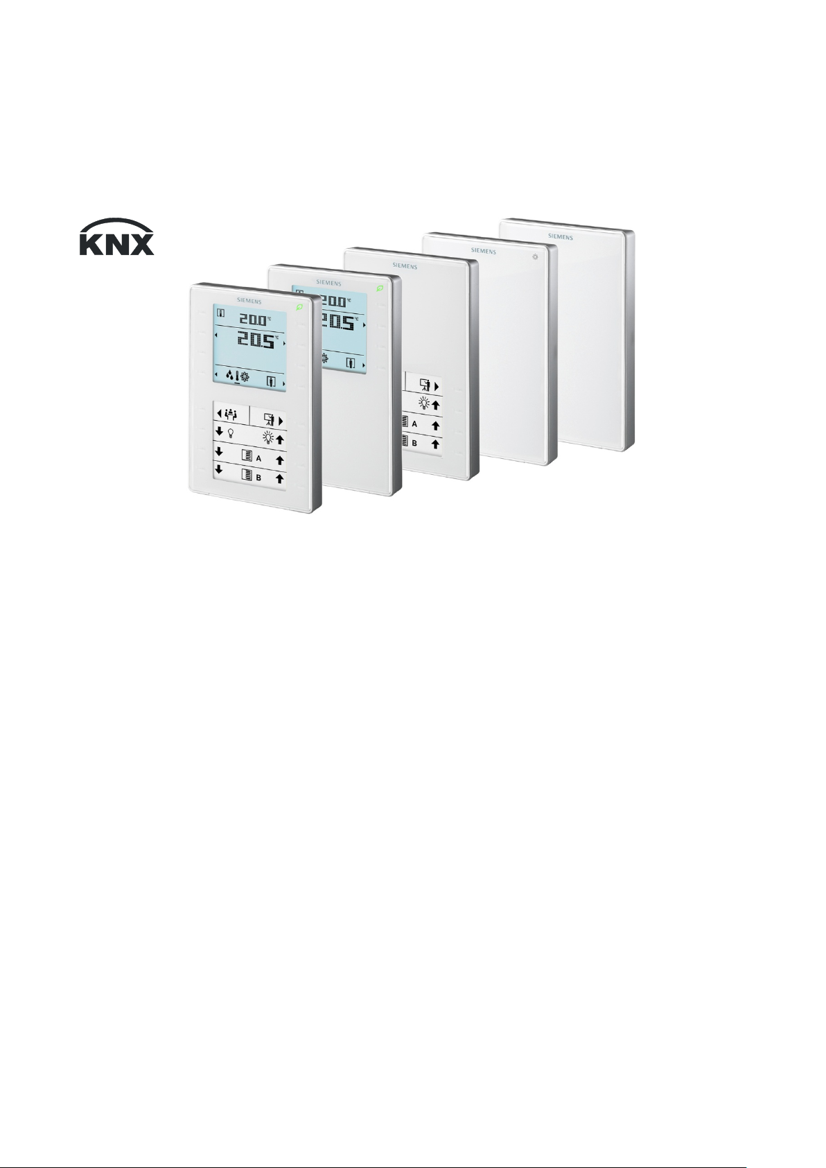
QMX3.P37 QMX3.P34/P74 QMX3.P02 QMX3.P70 QMX3.P30/P40
Wall
-mounted sensors and room operator units for
KNX/ETS and KNX/ACS
Technical principles
2018-09-14
Building Technologies
CM2N1602en_05
Page 2

Contents
About this document .............................................................................. 4
0
0.1 Revision history ......................................................................................... 4
0.2 Before you start ......................................................................................... 4
0.3 Abbreviations and naming conventions .................................................... 5
0.4 Reference documents ............................................................................... 5
1 Devices ..................................................................................................... 6
1.1 Type summary ........................................................................................... 6
1.2 Equipment combinations ........................................................................... 6
1.3 Variant and device parts ............................................................................ 7
1.4 Service and connection elements ............................................................. 8
1.5 Dimensions................................................................................................ 9
1.6 Environmental compatibility, disposal ..................................................... 10
1.6.1 General notes .......................................................................................... 10
1.6.2 Environmental declaration....................................................................... 10
1.6.3 Notes on FCC rules ................................................................................. 10
2 Safety and EMC optimization ............................................................... 11
2.1 Notes on safety ....................................................................................... 11
2.2 Device-specific regulations ..................................................................... 11
2.3 Notes on EMC optimization..................................................................... 11
3 Mounting and electrical installation .................................................... 12
4 Functionality / Use ................................................................................ 16
4.1 Overview ................................................................................................. 16
4.2 Use .......................................................................................................... 17
4.3 Display elements and buttons ................................................................. 18
4.4 Functions ................................................................................................. 19
4.4.1 Measuring................................................................................................ 19
4.4.2 Control and operation .............................................................................. 20
4.5 Application examples .............................................................................. 22
4.5.1 Room temperature control and operation via QMX3 .............................. 22
4.5.2 Presence dependent room climate control with operation
of all disciplines ....................................................................................... 23
4.5.3 Room temperature, humidity and air quality control ............................... 24
5 ETS engineering .................................................................................... 25
5.1 Engineering ............................................................................................. 25
5.2 Commissioning ........................................................................................ 25
5.3 Communication objects ........................................................................... 26
5.4 Room operator unit visualization and operation ..................................... 34
5.5 ETS Parameter description ..................................................................... 35
5.5.1 Room temperature sensor ...................................................................... 35
5.5.2 Room temperature control ...................................................................... 35
5.5.3 Room relative humidity sensor ................................................................ 37
5.5.4 Room relative humidity control ................................................................ 37
5.5.5 Room air quality sensor .......................................................................... 38
2 / 46
Siemens Wall-mounted sensors and room operator units for KNX/ETS and KNX/ACS CM2N1602en_05
Building Technologies Contents 2018-09-14
Page 3

5.5.6 Room air quality control .......................................................................... 38
5.5.7 Device display parameters ...................................................................... 38
5.5.8 HVAC operation and display ................................................................... 39
5.5.9 Operation and display: Relative humidity visualization ........................... 39
5.5.10 Display on QMX3.P70 Air quality indication LED .................................... 39
5.5.11 Operation and display: air quality............................................................ 40
5.5.12 Operation of light, shading and scenes .................................................. 40
5.6 Examples for the operation of touch keys and display elements ............ 42
6 ACS engineering ................................................................................... 44
6.1 Engineering ............................................................................................. 44
6.2 Commissioning........................................................................................ 44
6.3 ACS Parameter description .................................................................... 46
6.3.1 Communication ....................................................................................... 46
6.3.2 Universal temperature sensor ................................................................. 46
6.3.3 Room humidity sensor ............................................................................ 46
6.3.4 Room air quality sensor .......................................................................... 46
3 / 46
Siemens Wall-mounted sensors and room operator units for KNX/ETS and KNX/ACS CM2N1602en_05
Building Technologies Contents 2018-09-14
Page 4

0 About this document
Revision
Date
Changes
Section
Pages
• Communication objects
5.3 — 26
_03
2016-03-15
• Corrections/additions for V6.0
All
—
• Deleted section 5.1
_01
2013-07
First edition
—
—
Trademark(s)
Legal owner
KNX®
KNX Association, B - 1831 Brussels-Diegem Belgium
http://www.knx.org/
Trademarks
Copyright
Quality assurance
0.1 Revision history
_05 2018-09-14 • Corrections/additions for V6.1
_04 2017-03-10 • Corrections/additions for V6.1
• Added QMX3.P40
_02 2015-04 • Corrections for V5.1
0.2 Before you start
The trademarks used in this document and their lawful owners are listed in the
table below.. The use of trademarks is subject to international and domestic
provisions of the law.
All product names listed in the table are registered (®) or not registered (™)
trademarks of the owner listed in the table. These trademarks will not be indicated
elsewhere in the text (e.g. by use of symbols such as ® and ™) due to the
reference in this Section and to facilitate the reading of the text,
All
All —
5.3 —
This
document may be duplicated and distributed only with the express permission
of Siemens, and may be passed only to authorized persons or companies with the
required technical knowledge.
These documents were prepared with great care.
• The contents of all documents are checked at regular intervals.
• All necessary corrections are included in subsequent versions.
• Documents are automatically amended as a consequence of modifications and
corrections to the products described.
Please make sure that you are aware of the latest document revision date.
If you find any lack of clarity while using this document, or if you have any
criticisms or suggestions, please contact your local POC at the nearest branch
office. Addresses for Siemens RCs are available at www.siemens.com/sbt
4 / 46
Siemens Wall-mounted sensors and room operator units for KNX/ETS and KNX/ACS CM2N1602en_05
Building Technologies About this document 2018-09-14
Page 5

Before using our products, it is important that you read the documents supplied
Abbr.
Description
ACS790
Engineering Tool for Synco devices
ETS
Engineering Tool Software http://www.knx.org/
KNX/ACS
Communication with KNX, configuration with ACS
KNX/ETS
Communication with KNX, configuration with ETS
Use of documents /
Request to the reader
Abbreviations
Naming convention
with or ordered at the same time as the products (equipment, applications, tools
etc.) carefully and in full.
We assume that persons using our products and documents are authorized and
trained appropriately and have the technical knowledge required to use our
products as intended.
For more details on the products and applications, please refer to:
• On the internet: "Technical product data and descriptions" at
www.siemens.com/gamma-td
• On the intranet (for Siemens employees only) at
http://step.bt.siemens.com/portal/index.html
• At your next Siemens branch office www.siemens.com/sbt or at your system
suppliers.
• From the support team in the headquarters fieldsupport-
[email protected] if no local POC is available.
Siemens assumes no liability to the extent allowed under the law for any losses
resulting from a failure to comply with the aforementioned points or for the
improper compliance of the same.
0.3 Abbreviations and naming conventions
T
he term "room operator unit" in this document always refers to all types:
QMX3.P02. P30. P34, P70 und P74.
0.4 Reference documents
The following documents are available at www.siemens.com/gamma-td
[1] Data sheet N1602
[2] Mounting instructions M1692
[3] Word template for labels (QMX3.P02, P37) M1602.1
[4] KNX Standard, Volume 3: System Specifications, Part 7, Chapter 2: Data
oint Types (http://www.knx.org/
P
[5] Service- and Operating software ACS790 (Data sheet N5649)
)
Siemens Wall-mounted sensors and room operator units for KNX/ETS and KNX/ACS CM2N1602en_05
Building Technologies About this document 2018-09-14
5 / 46
Page 6

1 Devices
Temperature sensor Sensor for humidity
Sensor for CO
Air quality indicator
with LED Segmented backlit
display and touchkeys «Green leaf» LED Parameterizable touch-keys with LED display
dow for labels
1.1 Type summary
Product number Stock number Features
Sensors QMX3.P30
S55624-H103
2
X
Win
QMX3.P40
QMX3.P70
Room operator units QMX3.P02
QMX3.P34
QMX3.P74
QMX3.P37
Accessories QMX3.MP1
S55624-H11 6
S55624-H104
S55624-H107
S55624-H105
S55624-H106
S55624-H108
S55624-H11 0 Base plate for conduit box / cavity wall box for 68 mm
X X
X X X X
X X X
X X X
X X X X X X
X X X X X
diameter hole
20 pcs. per package
1.2 Equipment combinations
The room operator units are KNX certified and can be connected to all suitable
KNX devices, if the appropriate communication objects are available in the
application.
Use in the following BAC systems:
• GAMMA Building Management Systems / third-party devices
• Building automation and control systems with ETS configuration
Integration of third-party devices and free configuration.
• Synco700 (with ACS configuration) can only use the sensor information of types
QMX3.P30, QMX3.P40 and QMX3.P70.
6 / 46
Siemens Wall-mounted sensors and room operator units for KNX/ETS and KNX/ACS CM2N1602en_05
Building Technologies Devices 2018-09-14
Page 7
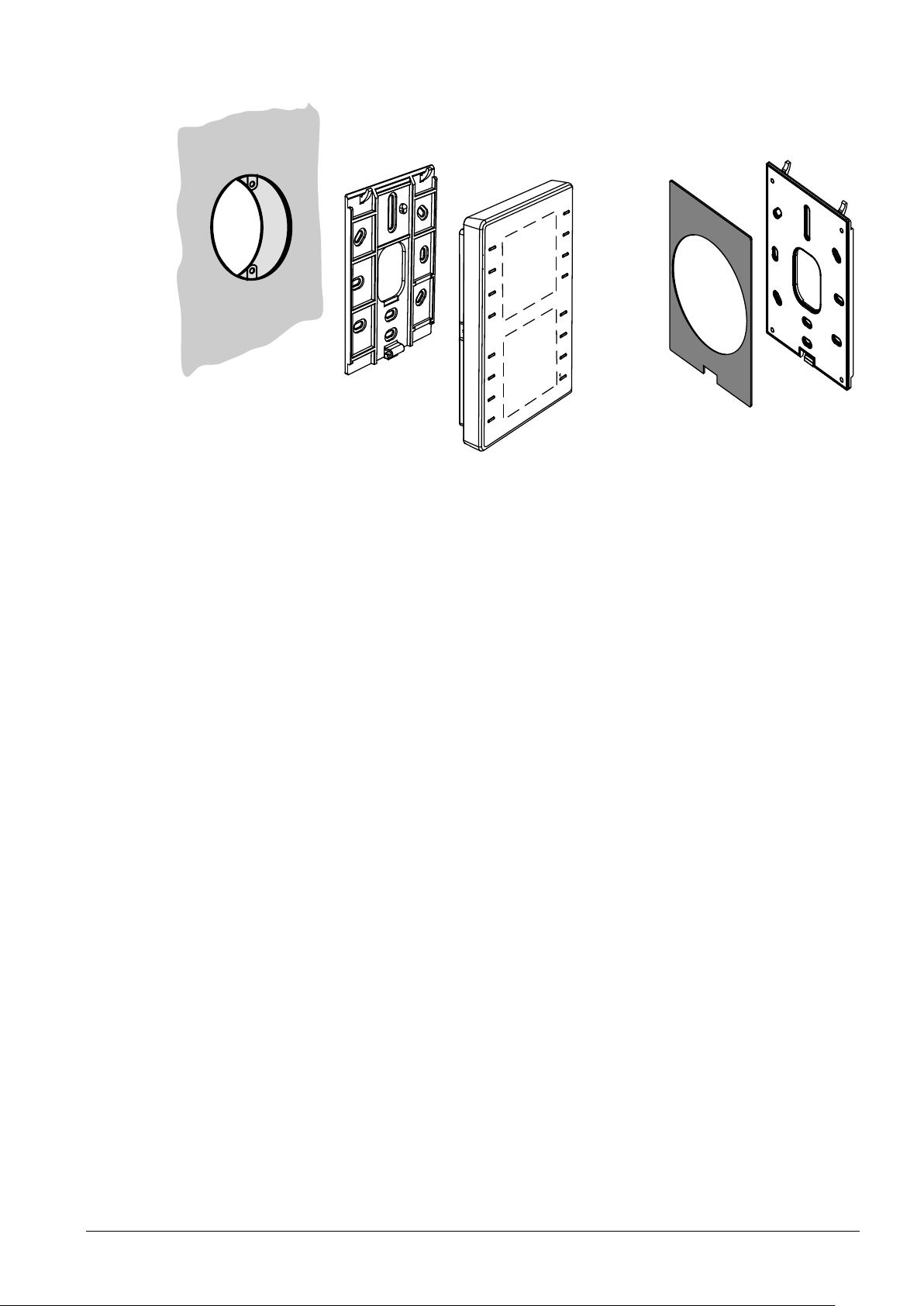
1.3 Variant and device parts
1602J01_01
B
C
A
B2
B1
Note
• T
he devices are designed for wall-mounting (A). A conduit box is optional.
– Conduit box: Keep in mind the dimensions of the conduit box!
– Cable conduits on the wall: Keep a distance of 30 mm (from above) /
20 mm (from below) to the base plate (B), so that the device (C) c
napped onto the base plate.
s
• The base plate (B) has screw holes for all common flush-mount boxes.
The screw head height must not exceed 3 mm.
• The device (C) incorporates a KNX / PL-Link plug, a tool plug, and, depending
on the type, sensor element, keys, LCD panel, window for the label.
The cable can be pushed into channels on the rear.
• A KNX plug is enclosed with the devices
an be
The optional metal-reinforced base plate QMX3.MP1 (B1) serves for two purposes:
• It is more rigid so that it does not bend when fixed in the middle with two screws
only (directly over a conduit box or a cavity wall box).
• It has a removable gray foam plate (B2) for mounting on a 68 mm diameter
cavity wall box. The plate compensates for the jutting edge of the box (s
m
ounting, page 13).
Q
MX3.MP1 is supplied in boxes with 20 pcs.
ee
7 / 46
Siemens Wall-mounted sensors and room operator units for KNX/ETS and KNX/ACS CM2N1602en_05
Building Technologies Devices 2018-09-14
Page 8
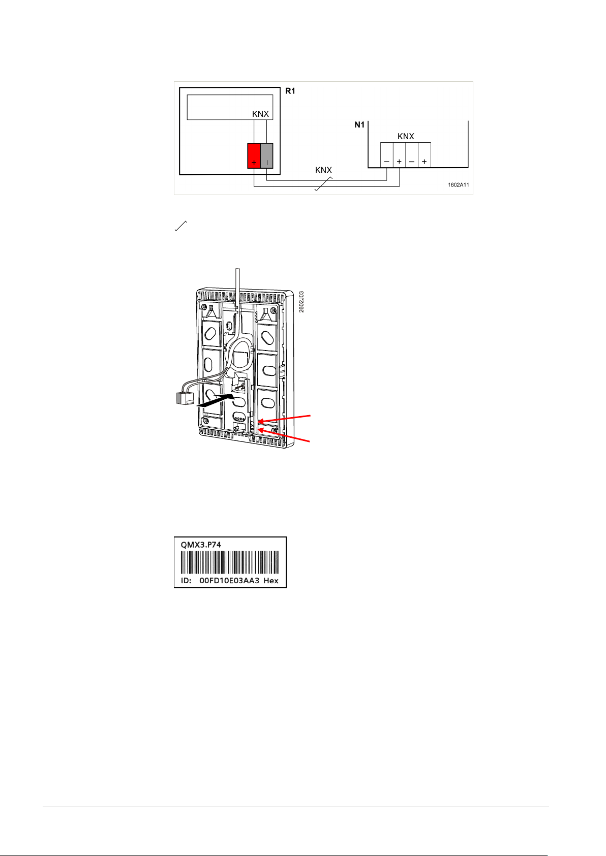
1.4 Service and connection elements
Connection
Service LED (red) and
programming pin
Adhesive address
labels
Simplifying engineering
and commissioning
R1 QMX3... Room operator unit
N1 Controller, actor
Twisted pair
Service LED (red)
Pr
ogramming pin
The s
ervice element functions are described Commissioning, sections 5.2 and 6.2.
The dev
ices are supplied with peel-off adhesive address labels containing the
unique KNX ID as alphanumeric and barcode display.
The addr
ess label can peeled off the device during mounting and stuck to a floor
plan or similar. The floor plan thus contains the assignment of KNX IDs and
physical installation location. This greatly simplifies the following steps. In addition,
the procedure serves as the basis for the recommended engineering and
commissioning process. If the adhesive labels are lost, all information is still
available in printed form on the housing.
8 / 46
Siemens Wall-mounted sensors and room operator units for KNX/ETS and KNX/ACS CM2N1602en_05
Building Technologies Devices 2018-09-14
Page 9
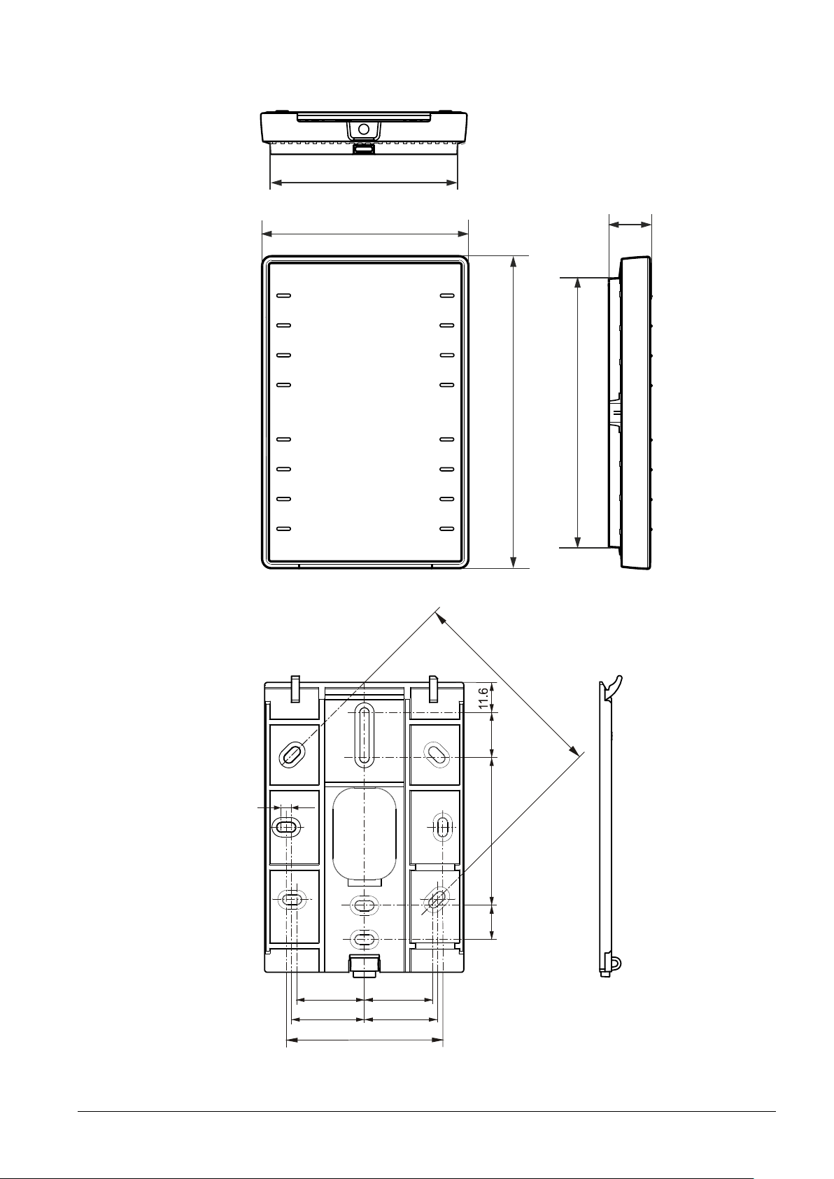
1.5 Dimensions
133.4
115
88.4
18
1602M01_01
80.5
78
.5
60
28.2
26.5
26
13.1
56.5
17.5
28.2
3.5
1602M02
Siemens Wall-mounted sensors and room operator units for KNX/ETS and KNX/ACS CM2N1602en_05
Building Technologies Devices 2018-09-14
9 / 46
Page 10

1.6 Environmental compatibility, disposal
Note
1.6.1 General notes
This device was developed and manufactured with environmentally compatible
materials and procedures complying with all relevant environmental standards.
Note the following to dispose of the product following its useful life or in case of
replacement:
• Do not dispose of the device as part of standard household garbage, but as
special waste from plastic and steel, ferrite-magnet components.
This applies in particular to the PCB.
• For this reason, dispose of the components compatible with current
environmental, recycling, and disposal technologies.
Observe all local, applicable laws.
• The aim is to reuse as much of the basic materials as possible at the lowest
possible environmental impact. To this end, note any material and disposal
notes in individual components.
1.6.2 Environmental declaration
The product environmental declaration CM2E1602 contains data on
environmentally compatible product design and assessments (RoHS compliance,
materials composition, packaging, environmental benefit, disposal)
1.6.3 Notes on FCC rules
This device complies with Part 15 of the FCC Rules. Operation is subject to the
following two conditions: (1) this device may not cause harmful interference, and
(2)this device must accept any interference received, including interference that
may cause undesired operation.
10 / 46
Siemens Wall-mounted sensors and room operator units for KNX/ETS and KNX/ACS CM2N1602en_05
Building Technologies Devices 2018-09-14
Page 11

Please comply
with these notes
General
regulations
Safety
KNX bus supply
Maintenance
Setting up
cable ducts
Cable types
Separate cables
Unscreened cables
2 Safety and EMC optimization
2.1 Notes on safety
This section explains general and system-specific regulations for mains and
operating voltages. It includes important information for your safety and the safety
of the entire plant.
lease comply with the following general regulations during engineering and
P
execution:
• Electrical and mains power ordinances for the given country.
• Other applicable, national regulations.
• Building installation regulations for the given country.
• Regulations of the utility company.
• Diagrams, cable lists, dispositions, specifications, and orders by the customer or
authorized engineering office.
• Third-party regulations, e.g. by the general contractor or building owner.
he electrical safety for building automation and control systems by Siemens is
T
essentially based on safely separating low voltage from mains voltage.
2.2 Device-specific regulations
Warning,
Note permissible line lengths and topologies when planning and installing
controllers and field devices featuring KNX bus connection. Make sure the bus
supply complies with the KNX standard.
Do not open the device.
The device is maintenance free. Only the manufacturer can repair the device.
2.3 Notes on EMC optimization
When setting up cable ducts, separate strongly interfering cables from susceptible
entities.
• Interfering cables: Motor cables especially from motors supplied by inverters,
energy-supplying cables.
• Susceptible entities: Control cables, low voltage cables, interface cables, LAN
cables, digital and analog signal cables.
oth types of cables may be in the same cable duct, but in separat
• B
c
ompartments.
• If no three-sided, closed duct with separating wall is available, the interferi
ables must be separated by at least 150 mm from the others or placed i
c
s
eparate ducts.
• Crossings of strongly interfering cables with possibly susceptible entities must
be at a right angle.
• In exceptional cases, signal and interfering power cables may be run in parallel,
resulting in a high interference risk.
e
ng
n
Siemens Wall-mounted sensors and room operator units for KNX/ETS and KNX/ACS CM2N1602en_05
Building Technologies Safety and EMC optimization 2018-09-14
W
e recommend to generally use unscreened cables. Comply with the
manufacturer's installation recommendations for selecting unscreened cables. In
general, unshielded twisted pair cables have sufficient EMC properties for
technical building applications (including data applications) and do not require
consideration of coupling to surrounding earth.
11 / 46
Page 12
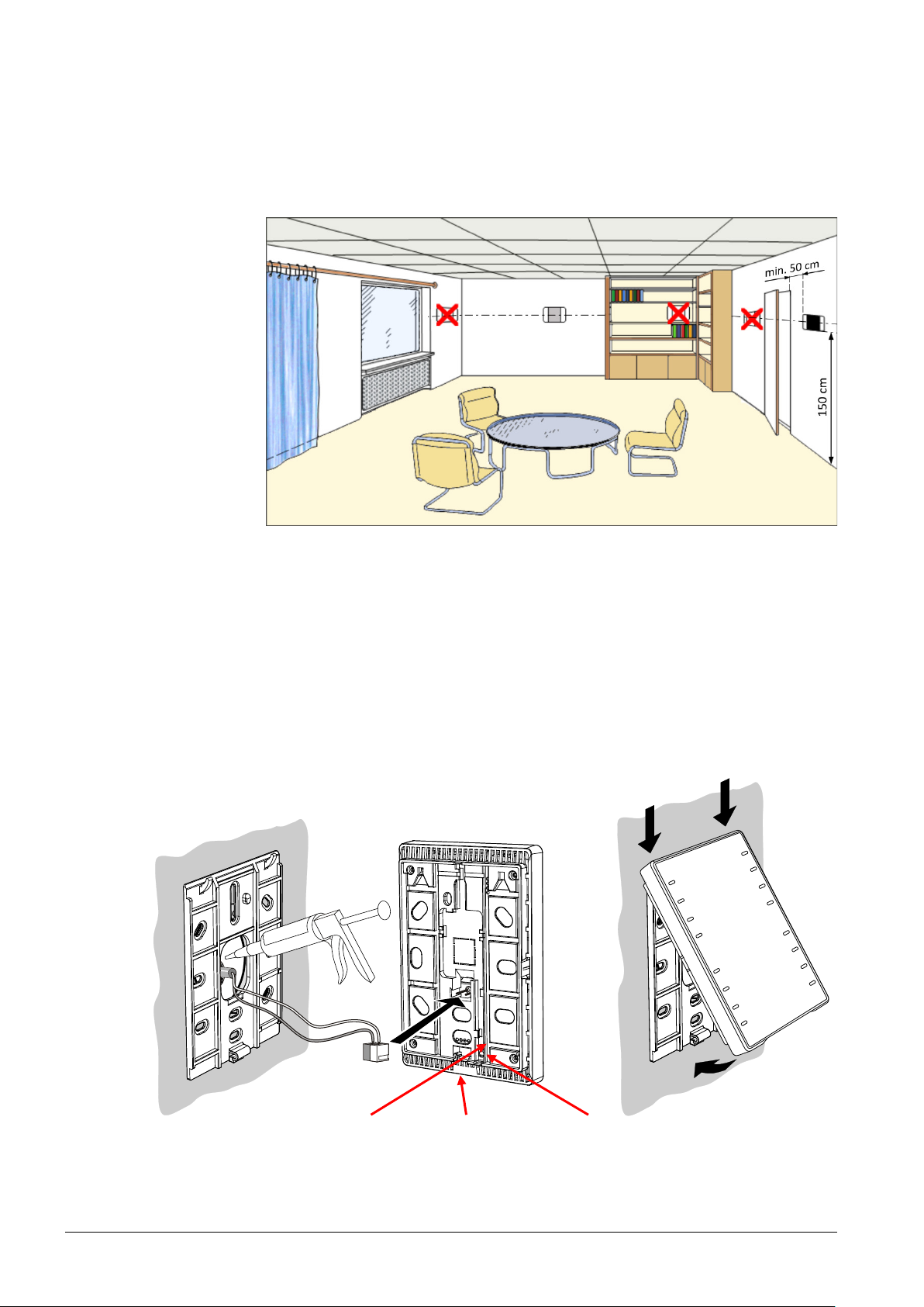
3 Mounting and electrical installation
Service LED (red) Tool plug Programming pin
2602J02
*
)
Ambient conditions
Location (sensors,
room operator units)
Mounting instructions
Mounting over a
conduit box
1602J108
Comply with the following notes as well as the mounting instructions [2] to mount
the room sensor.
Note the permissible ambient temperature and humidity. See data sheet [1] for
environmental conditions.
he devices are suitable for wall mounting.
• T
• Recommended height: 1.50 m above floor.
• Do not mount the devices in recesses, shelves, behind curtains or doors, or
above or near heat sources.
• Avoid direct solar radiation and drafts.
• Seal the conduit box or the installation tube, as air currents can affect sensor
readings.
• Adhere to allowed ambient conditions.
• Moun
ting instructions M1602 are enclosed with the devices.
12 / 46
Siemens Wall-mounted sensors and room operator units for KNX/ETS and KNX/ACS CM2N1602en_05
Building Technologies Mounting and electrical installation 2018-09-14
he installing tube must be sealed or cold or warm air may enter the device and
*) T
cause faulty temperature readings by the internal sensor.
Page 13
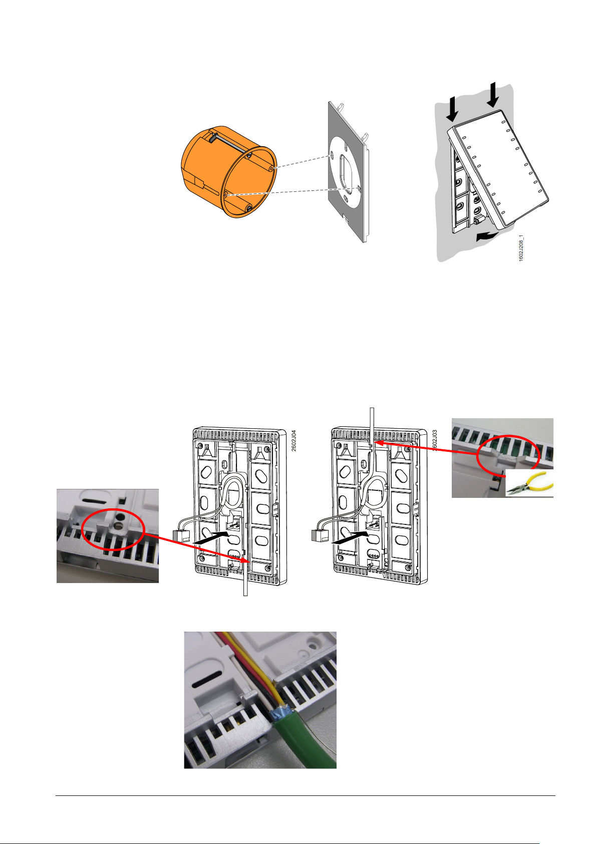
se a metal-reinforced base plate QMX3.MP1 instead oft he standard base plate
Monting over a cavity
wall box
1
1
223
U
delivered with the room operator unit.
he installing tube must be sealed or cold or warm air may enter the device and
T
cause faulty temperature readings by the internal sensor.
ixing the box on the cavity wall.
1 F
2 Fixing the QMX3.MP1 base plate on the box using 2 screws.
all mounting
W
4-wire cables
(daisy chain wiring)
3 The gray foam plate (removable) compensates for the jutting edge of the box so
that the plate is aligned with the wall.
Remove the breakout on the housing before putting the cable into the gaining channel.
Remove the cable coating, as it will not fit in
the gaining channel.
Siemens Wall-mounted sensors and room operator units for KNX/ETS and KNX/ACS CM2N1602en_05
Building Technologies Mounting and electrical installation 2018-09-14
13 / 46
Page 14
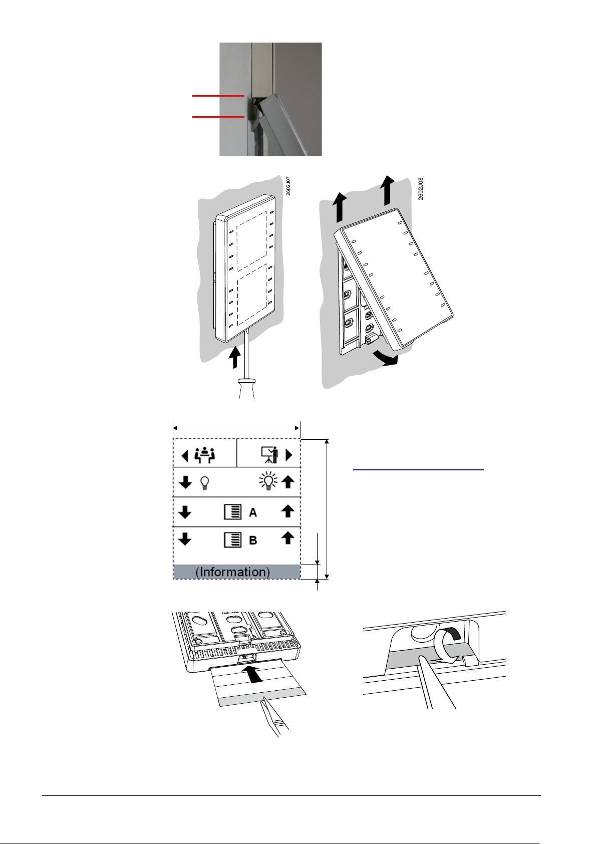
Cable ducts on the wall
M
ax
. 6
5
9
.2
±
0
.1
5
1
6
0
2
z
11
0
54 ± 0.15
Dismounting / service:
Labels for QMX3.P02,
QMX3.P37
Insert label
1602Z106
1602J109
Keep a distance of 30 mm (from above) /
20 mm (from below) to the base plate,
so that the device can be snapped onto the
base plate.
30 mm
ample icons are available in the label
S
template M1602.1 (Download from
www.siemens.com/gamma-td
)
Information. e.g. on room operator unit
location or on room type
(free text)
14 / 46
Siemens Wall-mounted sensors and room operator units for KNX/ETS and KNX/ACS CM2N1602en_05
Building Technologies Mounting and electrical installation 2018-09-14
Page 15
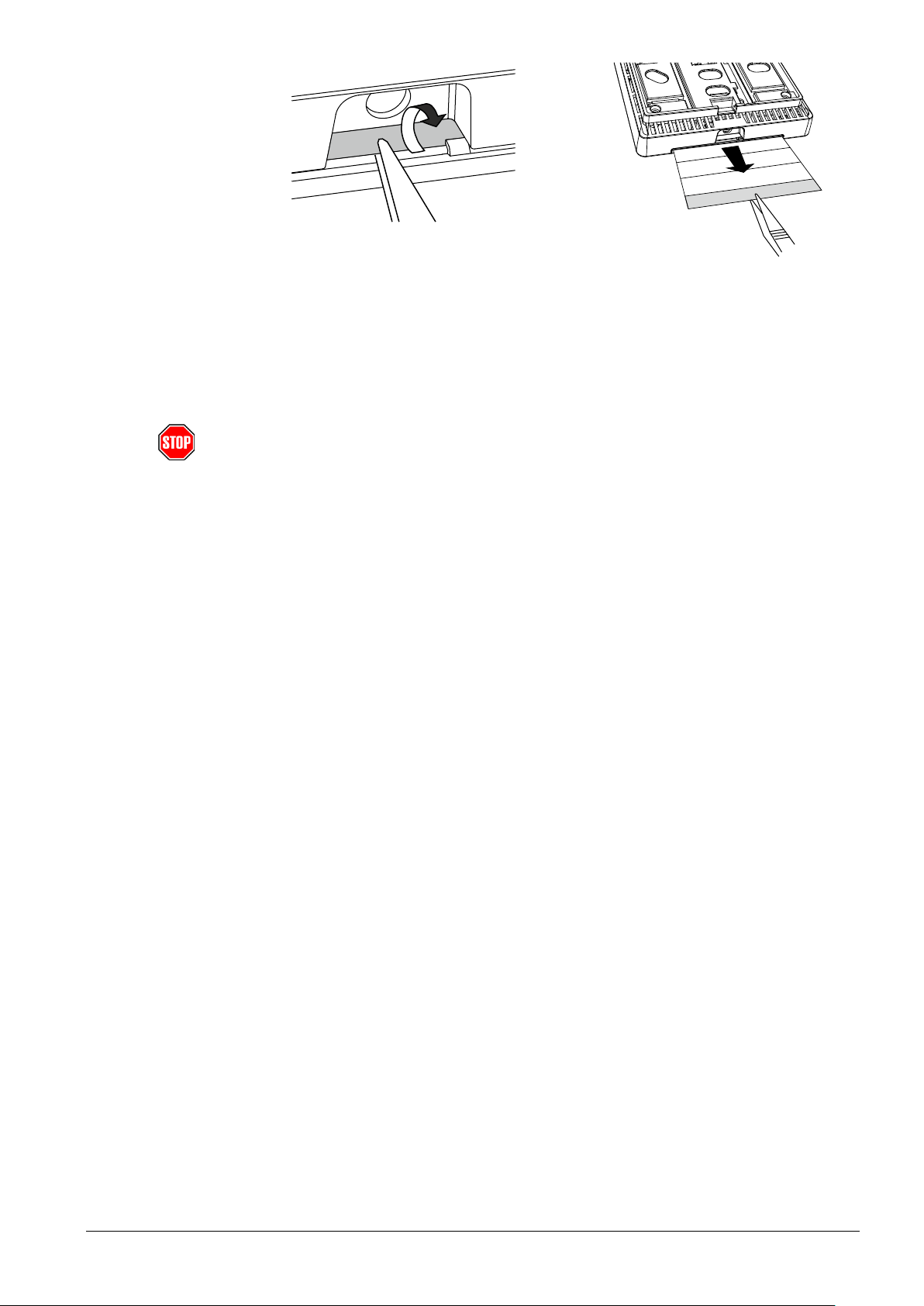
Remove label
Installation
Caution!
Bus cabling
1602J110
1602Z107
• Fol
low the KNX regulations
• For KNX wiring (topology, allowed cables and cable length), see the document
KNX bus [4].
• Use the correct cables for the KNX bus
• Do not interchange the wires of the KNX cable.
– The red terminal is for KNX +
– The gray terminal is for KNX –
erve all local installation regulations.
• Obs
e devices are not protected against accidental connection to AC 230 V.
Th
Inf
ormation in topology and addressing in KNX networks is available in document
KNX bus [4]. The following information requires electrical installation as per the
KNX-TP1 standard.
Siemens Wall-mounted sensors and room operator units for KNX/ETS and KNX/ACS CM2N1602en_05
Building Technologies Mounting and electrical installation 2018-09-14
15 / 46
Page 16
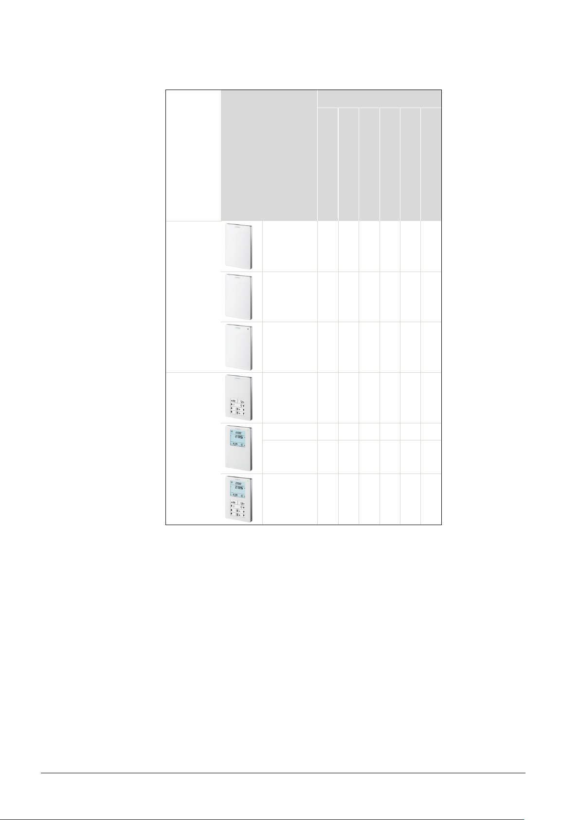
4 Functionality / Use
Temperature sensor Humidity sensor CO
Air quality indicator with LED Display and op
touchkeys Operation of light, shading and
scenes
4.1 Overview
Typ
Sensors QMX3.P30 X
QMX3.P40 X X
QMX3.P70 X X X X
Funktion
eration with
sensor
2
Room
operator
units
QMX3.P02 X X
QMX3.P34 X X
QMX3.P74 X X X X
QMX3.P37 X X X
16 / 46
Siemens Wall-mounted sensors and room operator units for KNX/ETS and KNX/ACS CM2N1602en_05
Building Technologies Functionality / Use 2018-09-14
Page 17

4.2 Use
Details
Six complementary device types are available which can control HVAC and electric
applications.
• Room temperature, humidity, and CO
cording to the demand and to energy efficiency criteria.
ac
• Four freely parameterizable pairs of touchkeys can be configured for light
switching, dimming, blinds, scenes, sending values, etc.
he sensors in the room operator unit measure:
T
– Room temperature.
– Relative room humidity.
– CO
concentration in rooms with varying occupancy due to time or number of
2
people such as in museums, movie theaters, offices, meeting rooms, class
rooms, auditoriums, hospitals, living spaces.
T
he room operator units control and operate:
– Room temperature (via PID controller)
– Humidity (via threshold value)
– Air quality (via threshold value)
– Fan stages (independent of temperature, air quality and humidity control
functions)
– Room operating modes
– Input of the occupancy state
content of the room are controlled
2
as well as
– Switching of electrical equipment
– Switching and dimming of lights
– Control of shading / blinds
– Selecting and saving of scenes
he room operator units with display show the following information about the
T
room:
– Present room temperature, outdoor temperature.
– Present room humidity, outdoor humidity .
– Present room air quality .
– State of window contacts
– Device mode (e.g. heating, cooling).
17 / 46
Siemens Wall-mounted sensors and room operator units for KNX/ETS and KNX/ACS CM2N1602en_05
Building Technologies Functionality / Use 2018-09-14
Page 18
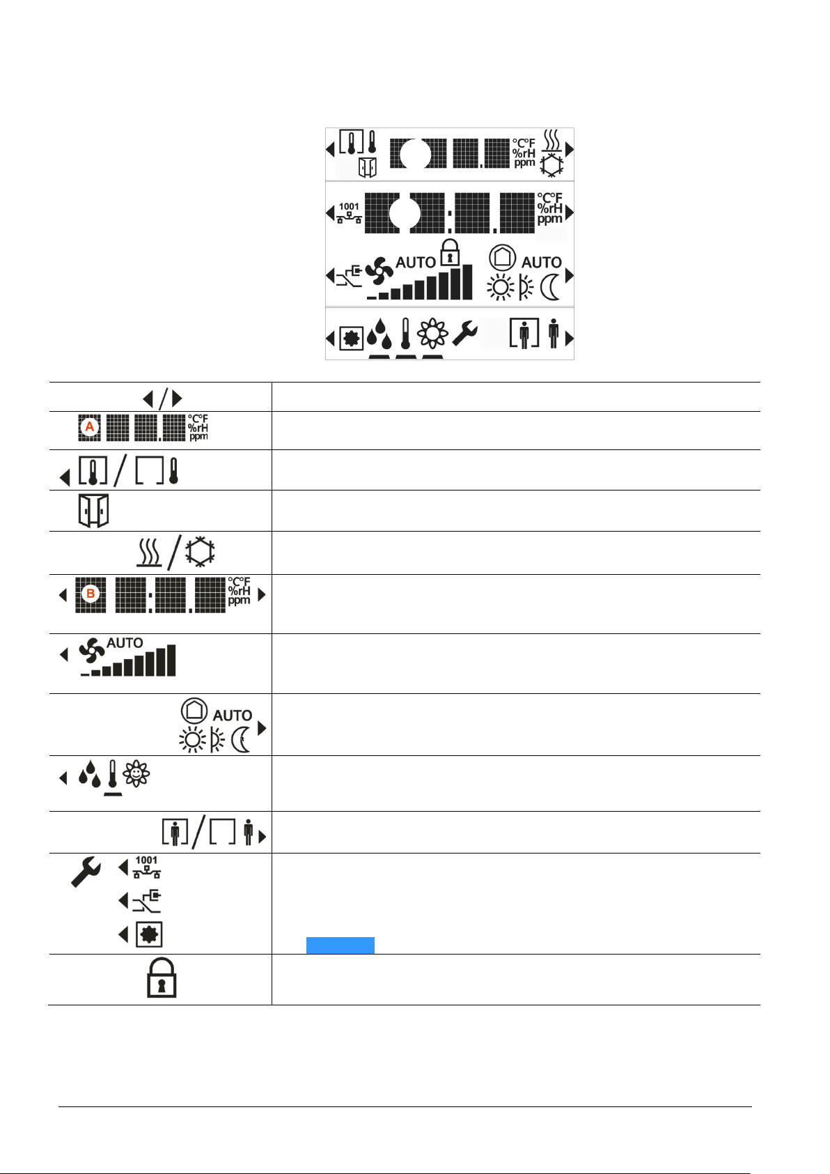
4.3 Display elements and buttons
Button
Button
air quality in text, symbol, or ppm of CO
2
(temperature, humidity, CO2)
• Adjusting the setpoint using keys 2 and 6
operating mode is disabled)
information.
• Engineering functions (press keys 1 and 8 simultaneously during 5 s)
NOTICE This operation is irreversible!
• Indicates that the room operator unit is locked by the system.
– The display in line 1 shows the temperature from bus
A
B
1
2
3
4
• An arrow indicates that an element can be operated
• Temperature display in °C or °F / humidity in % r.H. /
• Toggling (key 1) between indoor and outdoor measurement
• Indication that a window is open (connected window switch is active)
• Display of the plant state (Heating or Cooling / inactive)
Note: No manual switchover!
5
6
7
8
• D
isplay of the relative or absolute setpoint for temperature (Comfort)
Setpoints for room humidity and room CO
• D
isplay of the present fan speed (when automatic)
• Adjusting the fan speed using key 3 (or keys 3 and 7 if operation of room
• Display of the room operating mode (when automatic)
• Adjusting the room operating mode using key 7
• Navigation: toggle the display / setpoint setting between temperature /
humidity / CO
• Operation of the occupancy state (presence switch, Comfort extension)
• Activate the Comfort extension using key 8 (only available if enabled)
– Programming mode (key 2), same function as programming pin
(service pin) on the back of the device
– Connection test (Key 3) (not supported by ETS and ACS)
– Reset device to factory settings (key 4)
– Operation is disabled
, using key 4. The black bar points to the displayed
2
concentration.
2
18 / 46
Siemens Wall-mounted sensors and room operator units for KNX/ETS and KNX/ACS CM2N1602en_05
Building Technologies Functionality / Use 2018-09-14
Page 19

The digits "0xxx" and "00xx" are displayed on power-up:
Temperature
(All Types)
Relative humi
(QMX3.P70, QMX3.P74)
CO2 concentration
(QMX3.P70, QMX3.P74)
Air quality indication
(QMX3.P70)
0xxx is the FW version
00xx is the Build version
4.4 Functions
The room operator units with control functions can be integrated in a KNX network.
The control functions for room temperature and ventilation allow for immediate
control of suitable actuators to control heating, cooling, and ventilation.
4.4.1 Measuring
he room operator units measure the room temperature via an integrated sensing
dity
T
element. The room temperature can be transmitted to other bus members and
serves in KNX as control variable of the integrated room temperature controller.
The outdoor temperature received via the KNX bus is only used for indication on
the display and has no effect on the control.
he room operator units acquire the relative humidity in the room with the aid of a
T
humidity sensing element integrated in the front module. The relative room
humidity can be transmitted to other bus members and serves in KNX as control
variable of the integrated ventilation controller.
The room operator units determine the CO
concentration via infrared absorption
2
measurement (NDIR). The sensor provides exact measurements at all times and
does not require maintenance or recalibration thanks to an integrated, stable
reference light source. The CO
concentration can be transmitted to other bus
2
members and serves in KNX as control variable of the integrated ventilation
controller.
The background-lit symbol informs on the current level of CO2 in the room. The
colors green / orange / red of the background lighting indicate good / moderte /
poor air quality. The display can be switched on or off by another bus member, e.g.
switch or timer.
Siemens Wall-mounted sensors and room operator units for KNX/ETS and KNX/ACS CM2N1602en_05
Building Technologies Functionality / Use 2018-09-14
19 / 46
Page 20
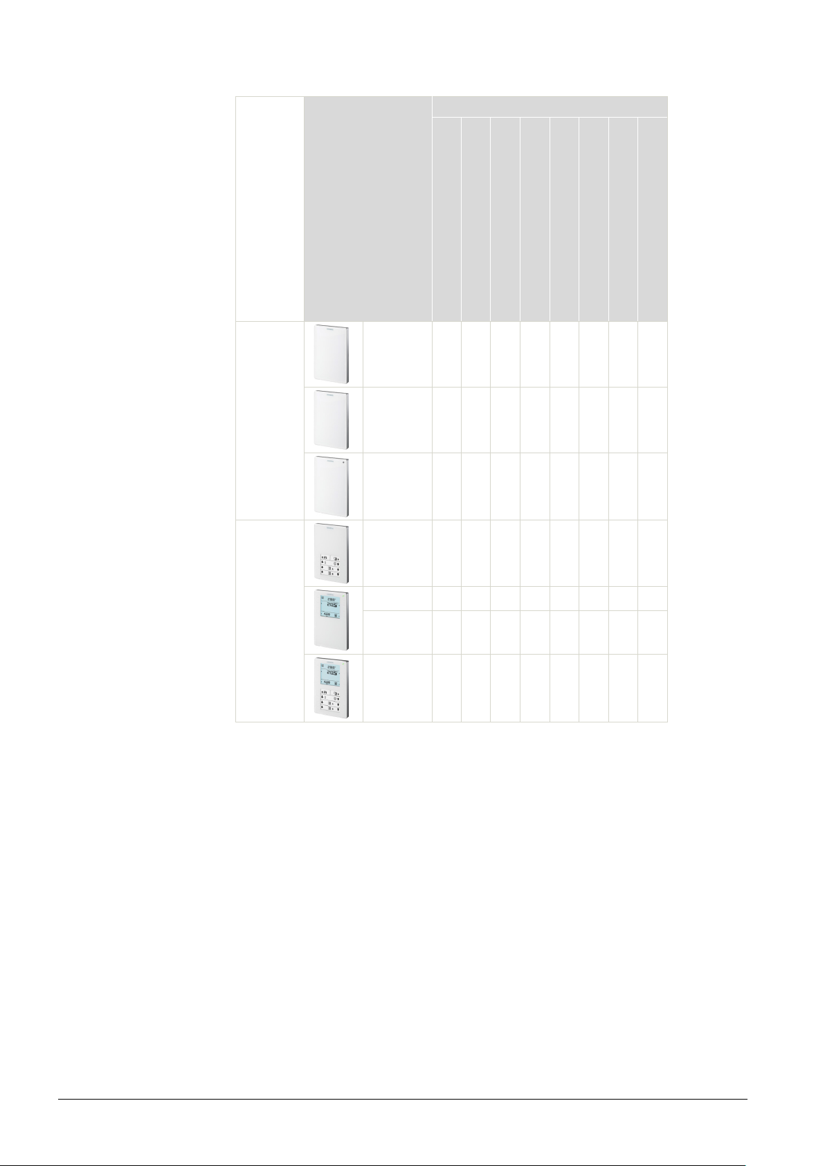
4.4.2 Control and operation
PID control temperature Threshold value switch humidity Threshold value switch CO
Operation of light, shading and scenes Manual switching of ventilati
Room operating mode Presence function Only operation and display
Control functions
(KNX all types)
Sensors
Typ
QMX3.P30 X X
QMX3.P40 X
QMX3.P70 X X X
Regelung und Bedienung
2
on
Room
operator
units
he room operator units can be connected via bus to suitable KNX heating,
T
QMX3.P02 X X X
QMX3.P34 X X X X X X
QMX3.P74 X X X X X X X
QMX3.P37 X X X X X X X
ventilating, and air conditioning actuators via integrated control functions for room
temperature, humidity, and air quality.
A proven PID controller for heating and cooling is provided to control the room
temperature. The controller supplies a continuous or a pulse-width-modulated PID
signal for one heating and one cooling actuator. The room temperature setpoints
for the two operating modes heating and cooling as well as a blocking object can
be set using the touchkeys and the display, or received from the bus. Changeover
to the operating mode Heating/Cooling is automatic. Preset control parameters,
adjusted for the heating type or cooling type, are available for selection.
20 / 46
Siemens Wall-mounted sensors and room operator units for KNX/ETS and KNX/ACS CM2N1602en_05
Building Technologies Functionality / Use 2018-09-14
The integrated room humidity controller and room air quality controller can be
used for ventilation control. For both controllers, the setpoints can be adjusted
using touchkeys and display, or they can receive up to three switching point values
via the bus.
When the respective switching point is exceeded, up to three control signals and
one quasi-continuous signal to control the ventilation actuators are transmitted to
other bus members. In addition, a signal with the max. control value from both
Page 21

[ppm]
Typical CO2 concentration
<400
Outside air
700
City air
1000
Comfort limit
2000
Inacceptable indoor air quality
4000
Bedroom at poor ventilation
5000
Max. concentration for workspaces (MAC value)
Altitude [m]
0
500
1000
1500
2000
2500
3000
CO2 [ppm]
1000
1095
1201
1317
1445
1586
1740
Fan control
(QMX3.P34, P74, P37)
controllers is available.
The setpoint (from local operation or received via bus) directly influences the first
threshold value (see description in sections 5.5.4 and 5.5.6).
Room temperature controller, humidity threshold value, and air quality threshold
switching can be activated or deactivated. As a result, simple sensor function or
room operation is possible also.
Manu
al room fan control can be enabled, offering three different types for selection
such as single stage, 3 stages, or continuous from 0 to 100 percent. The 9 display
bars change after 10% (display: 10% one bar, …100% 9 bars). For manual
operation, a bar is added on each button press, corresponding to a change of +/11%. This function can be activated or deactivated.
Fan control is independent of the room temperature. When the fan operating mode
is Auto, the setpoint value via bus is executed.
Room operating modes
(QMX3.P34, P74, P37)
Presence button
(QMX3.P34, P74, P37)
Comfort extension
(QMX3.P34, P74, P37)
Air quality measurement
and assessment
(QMX3.P70, QMX3.P74)
T
he room operating modes can be controlled from Auto to Comfort, Pre-Comfort,
Economy, and Protection. This function can be activated or deactivated.
The presence button allows for manual changeover between Comfort and PreComfort. This function can be activated or deactivated. When activated, the
Comfort extension is not available (key 8, see section 4.3).
W
hen the presence function is deactivated, Comfort can be extended.
Extensions are set between 5 and 120 minutes in ETS.
This function can be activated or deactivated (key 8, see section 4.3.
he following table provides information on assessing room air quality based on
T
the determined CO
1500 Ventilation strongly recommended
concentration.
2
Notes on CO2 sensor
Siemens Wall-mounted sensors and room operator units for KNX/ETS and KNX/ACS CM2N1602en_05
Building Technologies Functionality / Use 2018-09-14
40000 Exhaled air
CO
concentration measurements are influenced by air pressure and temperature.
2
The lower the air pressure, the lower the measured value. Temperature influence is
corrected automatically. The sensor allows for correcting the determined measured
value to the prevailing average air pressure at the mounting location. To do this,
altitude [m above sea level] must be set. The correction has the following effect on
an uncorrected measured value of 1000 ppm at normal conditions (0 m altitude,
25 °C):
• F
unction: The sensor determines the CO
concentration via infrared absorption
2
measurement (NDIR). The sensor is maintenance free in normal environments,
thanks to the built-in self-correcting ABC (Automatic Baseline Correction)
algorithm. This algorithm keeps track of the sensor’s lowest reading within
8
21 / 46
Page 22
days and corrects for any drift detected. The sensor also contains self-
Operation of light,
shading and scenes
(QMX3.P37, QMX3.P02)
diagnostics to assure proper operation during lifetime.
se: Normal environments, such as offices, class rooms, hotel rooms, or other
• U
non-permanently occupied areas, typically reach at least once a week the CO
oncentration of fresh air of 400 ppm. However, exposure to a lowest CO
c
2
2
concentration other than fresh air, or incorrect altitude parameter setting, might
result in reduced accuracy and incorrect operation.
• Rough handling during transport, storage or mounting might adversely affect
accuracy during the first days of operation.
• The specified accuracy is reached after 25 days of continuous operation.
tons (individual or button pairs) and related LEDs can be parameterized
8 but
individually. See Section 3 for button labels.
Common functions such as switching (On, Off, toggle) or sending of values
(percentage), dimming, or blinds control, 8-bit scene control with/without memorize
are supported.
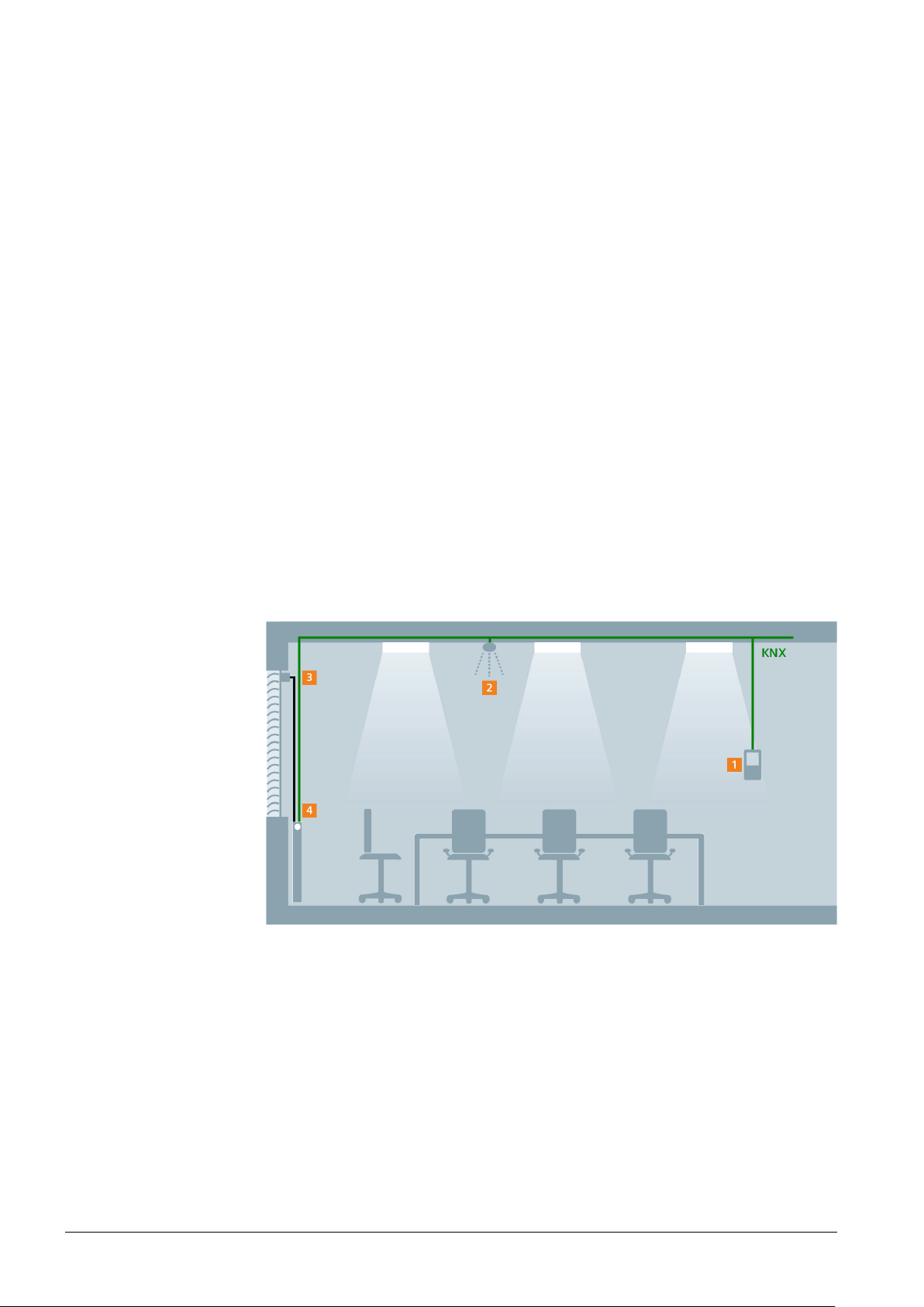
4.5 Application examples
Below are a few typical application examples for the QMX3.P30, P34, P70 and P74
room operator units.
4.5.1 Room temperature control and operation via QMX3
Key (Possible combination of components)
1. Room operator unit QMX3.P34
2. Presence detector UP 258
3. Motoric valve actuator AP 562/02
4. Window contact S 290
22 / 46
Siemens Wall-mounted sensors and room operator units for KNX/ETS and KNX/ACS CM2N1602en_05
Building Technologies Functionality / Use 2018-09-14
his application is recommended for smaller offices with a single heater.
T
The room operator unit measures and regulates room temperature and sends the
regulation signal to the valve drive actuator via KNX bus.
In addition, window contacts and presence detectors influence the control behavior
of the room operator unit and increase the room‘s energy efficiency. For example, if
Page 23
no one is in the room or if the window is open, the radiator valve closes and
reduces the room temperature automatically. Up to 4 window contacts and
presence detectors can be connected via KNX bus.
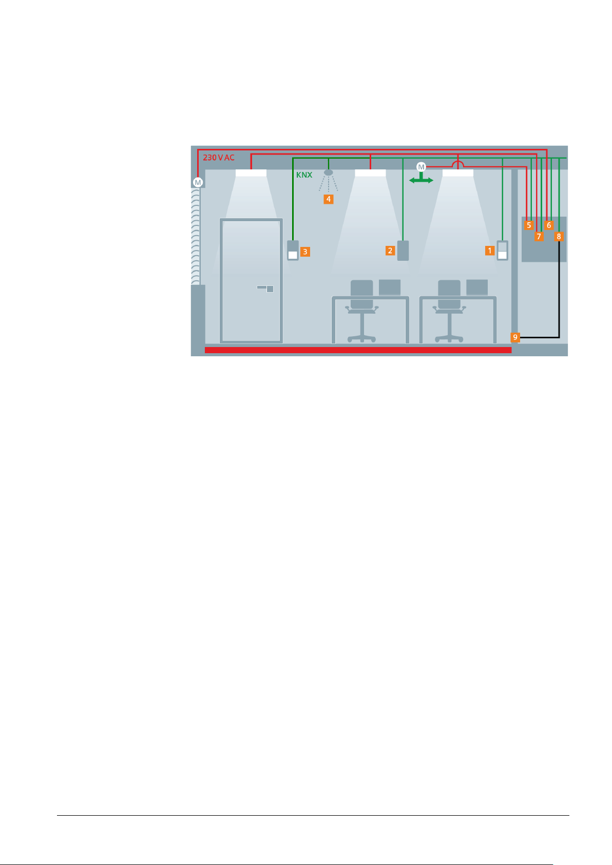
4.5.2 Presence dependent room climate control with operation of all disciplines
Key (Example of a possible combination of components)
1. Room operator unit QMX3.P02
2. Room sensor QMX3.P70
3. Room operator unit QMX3.P37
4. Presence detector UP 258
5. Switch actuator N 562/11 for fan
6. Shutter/blind actuators N 523/04
7. Universal dimmer N 528/31 with sub-module N 528/41
8. Thermal drive actuator N 605 for up to 6 rooms
9. Thermal valve actuator STA23 (up to 4 per room)
T
his application is especially suitable for rooms with several heaters, e.g. in offices,
lecture halls or conference rooms.
The room operator unit (1) measures and controls the room temperature and
sends the control signal to the thermal actuator (8) via KNX bus. Together with the
integrated room temperature control, the sensor provides for a comfortable room
climate.
The Room operator unit (2) measures the air quality (CO
) in the room, controls the
2
ventilation as required and thus saves energy and costs. The buttons on the room
operator unit (1 and 3) can be used to control shading, lighting and scenes for
example.
Additional room operator units (1) can also be connected, e.g. in large rooms with
several doors.
23 / 46
Siemens Wall-mounted sensors and room operator units for KNX/ETS and KNX/ACS CM2N1602en_05
Building Technologies Functionality / Use 2018-09-14
Page 24
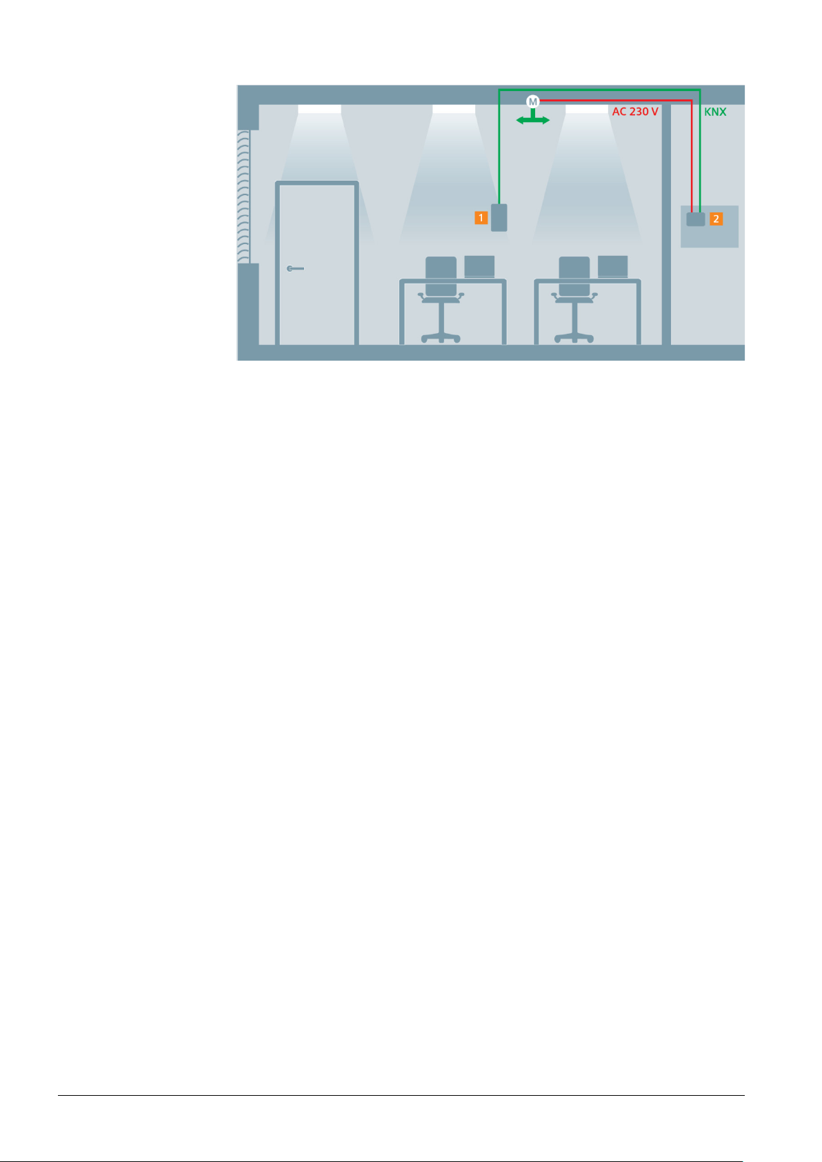
4.5.3 Room temperature, humidity and air quality control
Key (Possible combination of components)
1. Room sensor QMX3.P70, including – Temperature sensor
2. Air handling controller RMU7x0B
– Humidity sensor
sensor
– CO
2
The room operator unit (1) measures the room temperature, the room humidity,
and the CO
concentration, and passes these values on to the controller (2) via the
2
KNX bus. The controller controls temperature, humidity and air quality of the
corresponding room based on the measured values.
24 / 46
Siemens Wall-mounted sensors and room operator units for KNX/ETS and KNX/ACS CM2N1602en_05
Building Technologies Functionality / Use 2018-09-14
Page 25

5 ETS engineering
Pushbutton actuation
Meaning
connection test.
pressed longer (> 2 s to 5 s).
This operation is irreversible.
LED indication
Meaning
Red
Device is in programming mode.
Product data
ETS version
Functionality of touch
keys and display
Commissioning
prerequisites
Pushbuttons
LED status indication
Switch-on response
5.1 Engineering
The product data (*.vd5 or *.knxprod) must be downloaded from the website and
imported in the ETS for engineering. The product data is available at
www.siemens.com/hvac-td or www.siemens.com/gamma-td
f ETS3 is used, make sure to install first ETS3 patch (additional software column
I
SW) for ETS3.0f www.siemens.com/hvac-td
For ETS4, make sure the latest version is installed or at least version 4.1.2.
F
or a series of examples see section 5.6.
5.2 Commissioning
Prior to commissioning, all devices must be mounted as per the mounting
instructions [2] and connected to the bus via bus connector as per to the bus
topology (red to +, black to –). To check correct polarity of the wires for of a bus
participant, press the programming pin if the bus is powered. If the service LED
lights up, the polarity of the wires is correct
.
Short (< 2 s) Switch over to programming mode or acknowledge display of a
No functions are executed when the programming button is
Long (> 20 s)
Note!
Reset to factory settings.
This operation resets all user preference data and parameter
settings to factory default.
All other indication types do not apply to KNX.
D
uring parameterization using the commissioning software, the input objects are
set to default values upon initial switch-on or following standard reset.
In the event of a bus voltage failure, the device detects the failure and saves the
values received last to non-volatile memory. After bus power restoration, the saved
status of all input objects is restored. The status values received via the bus for the
LEDs of keys A1 to D2 are not stored.
Siemens Wall-mounted sensors and room operator units for KNX/ETS and KNX/ACS CM2N1602en_05
Building Technologies ETS engineering 2018-09-14
25 / 46
Page 26
5.3 Communication objects
Obj. Object name Function Type / Lengt h Fl
a gs
QMX3.P30
QMX3.P40
QMX3.P70
QMX3.P34
QMX3.P74
QMX3.P02
QMX3.P37
Room temperature sensor
1 Room Temperature [°C] Temperature value in °C
9.001
2 bytes
CRT X X X X X X X
Room temper ature c ontroller
2 Room temp. controller operating mode
HVAC control type (0 = Auto,
1 = Heating, 3 = Cooling, 6 = Off)
20.105
1byte
CRWU X X X X X X X
3 Enable room temperature controller Controller on = 1 / off = 0
1.003
1 bit
CRWU X X X X X X X
4 Room temperature setpoint while cooling Cooling temp. setpoint in °C
9.001
2 bytes
CRWU X X X X X X X
5 Room temperature setpoint while heating Heating temp. setpoint in °C
9.001
2 bytes
CRWU X X X X X X X
6 Control value cooling - cont (0..100%)
5.001
1 byte
CRT X X X X X X X
7 Control value heating - cont (0..100%)
5.001
1 byte
CRT X X X X X X X
8
Control value cooling - on/off On/Off
1.001
1 bit
CRT X X X X X X X
9
Control value heating - on/off On/Off
1.001
1 bit
CRT X X X X X X X
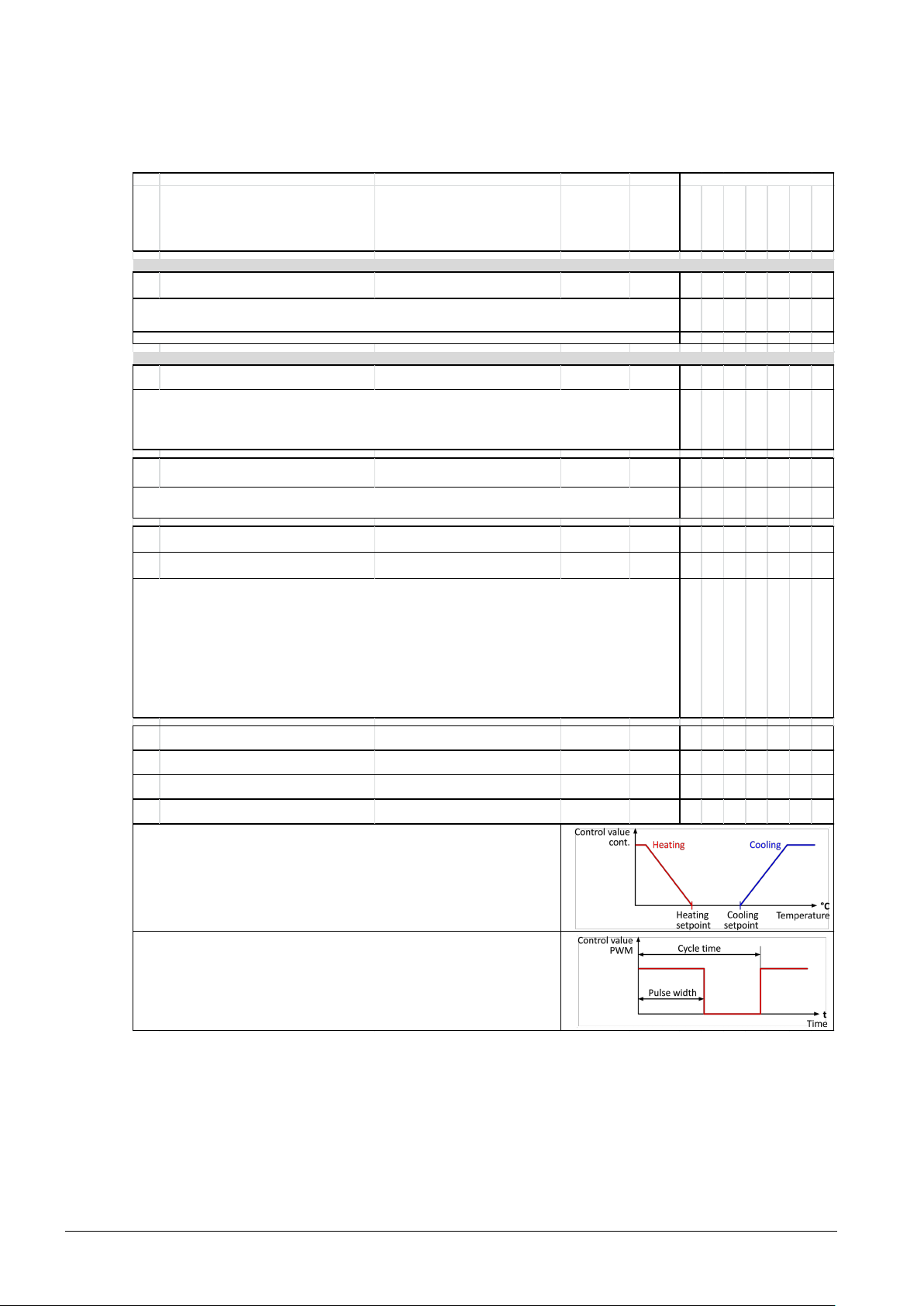
The parameters Heating/cooling type adapt the controller to the heating type.
In addition, the controller knows two control algorithms, one for modulating mode (0..100%)
and one for PWM m ode (on/off). The parameter "Positioning signal type" selects the mode. The
positioning signal type is the same for all operating m ode.
I
n modulating mode (Obj. 6, 7), for a modulating positioning signal ≠ 0, the applicable,
associated PWM output is "on".
Devices
Provides the room temperature value from the integrated sens or.
Value of the outside temperature sensor: See object 53.
Must be placed in a group address to display the value on the display.
In the operating mode "Auto", the controller independently changes over between heating and cooling mode.
But only either the cooling or heating mode is always active.
If the object room temperature controller is enabled, the operating mode can changeover between "Off” (Obj. 3 = 0) and
"Auto” (Obj. 3 = 1). The standard operating mode is "Auto”.
The operating m ode switches to "Auto" if the room temperature controller is enabled (1 = Controller on).
The operating m ode switches to "Off" when s witching off (0 =
Controller off). The default value is controller on = 1.
The setpoints for cooling and heating mode do not lock out each other. In operating mode "Auto”, for
cooling setpoint <
heating setpoint, the heating m ode is nevertheless active.
The controller's comfort setpoints can be adjusted over the bus using these objects.
As long as no other values are received by the bus or adjusted on the device with display, the received setpoints of objects
4 and 5 appl
y.
Objects 4 and 5 act directly on the internal controller. The display on the device does not change!
In other words, you can adjust the active cooling setpoint as desired using object 4 (without limiting by the heating
setpoint) without this being visible on the display. The display for setpoint and operating m ode rem ain unchanged. Object
4 is once again overwritten if something is adjusted on the device (s etpoint and operating mode).
In other words, you can influence the controller for short periods using both objects .
In PWM mode (Obj. 8, 9 as well as Obj. 6, 7), the cycle time and pulse length is adapted to the
type of heating, the s etpoint, and the meas ured room temperature. The minim um cycle is 12
minutes; the minimum pulse length 4 minutes. The modulating positioning signal outputs
values 0% or 100% in this operating mode.
The number and type of available objects as well as adjustable parameters can
vary depending on basic configuration. For detailed documentation on KNX data
point types, see [5].
26 / 46
Siemens Wall-mounted sensors and room operator units for KNX/ETS and KNX/ACS CM2N1602en_05
Building Technologies ETS engineering 2018-09-14
Page 27

Obj. Object name F
unction Type / Length Fl a g s
QMX3.P30
QMX3.P40
QMX3.P70
QMX3.P34
QMX3.P74
QMX3.P02
QMX3.P37
Room temperature se tpoint, ope ra ting modes, window state , occ upanc y
10 Room temperature: Setpoint absolute [°C]
9.001
2 bytes
CRW
U
X X X X
11 Room temperature: Setpoint relative [K]
9.002
2 bytes
C
WU
X X X X
12 Room temperature: Setpoints heating
222.100
6 bytes
CRWU
X X X X
X X X
13 Room temperature: Setpoints cooling
222.100
6 bytes
CRWU
X X X X
X X X
14 Room operating mode: Tim e switch
1= Comfort, 2 = Precomfort,
3 = Eco, 4 = Protection
20.102
1 byte
CRW
U
X X X X X X X
15 Room operating mode: Preselection
0 = Auto, 1= Comfort, 2 = Precomfort,
3 = Eco, 4 = Protection
20.102
1 byte
CRW
U
X X X X
16 Room operating mode: State
1= Comfort, 2 = Precomfort,
3 = Eco, 4 = Protection
20.102
1 byte
CRT
X X X X X X X
17 Comfort m ode: Timer button Activate comfort extension
1.017
1 bit CW
X X X X X X X
X X X X X X X
18 S
tate window 1 (1=open / 0=close) 1 = Open / 0 = Closed
1.019
1 bit
CRW
U
X X X X X X X
19 State window 2 (1=open / 0=close) 1 =
Open / 0 = Closed
1.019
1 bit
CRW
U
X X X X X X X
20 State window 3 (1=open / 0=close) 1 =
Open / 0 = Closed
1.019
1 bit
CRW
U
X X X X X X X
21 State window 4 (1=open / 0=close) 1 = Open / 0 = Closed
1.019
1 bit
CRW
U
X X X X X X X
X X X X X X X
22 Presence state 0 = non-occupancy / 1 = occupancy
1.018
1 bit
CRW
U
X X X X X X X
23 Room temperature: Setpoint Heating [°C]
9.001
2 bytes
CRT
X X X X X X X
24 Room temperature: Setpoint Cooling [°C]
9.001
2 bytes
CRT
X X X X X X X
160 Room temperature: Economy heating s etpoint Temperature (°C)
9.001
2 bytes
C
WU
X X X X X X X
161 Room temperature: Precomfort heating setpoint Temperature (°C)
9.001
2 bytes
C
WU
X X X X X X X
162 Room temperature: Comfort heating setpoint Temperature (°C)
9.001
2 bytes
C
WU
X X X X X X X
163 Room temperature: Comfort cooling setpoint Temperature (°C)
9.001
2 bytes
C
WU
X X X X X X X
164 Room temperature: Precomfort cooling setpoint Temperature (°C)
9.001
2 bytes
C
WU
X X X X X X X
165 Room temperature: Economy cooling setpoint Temperature (°C)
9.001
2 bytes
C
WU
X X X X X X X
The extension time can be configured.
Units with display: Must be placed in a group address to display operation/s ymbol on the display.
These objects available only when PID control is enabled.
Units with display: Objects must be placed in a group address to display open window symbol on the display.
(corresponds to object 55 for units with display)
(corresponds to object 56 for units with display)
This is a setpoint set. It can be used to adjust all heating setpoints (Comfort, Precomfort and Eco)
This is a setpoint set. It can be used to adjust all cooling setpoints (Comfort, Precomfort and Eco)
The controller operating mode mus t be set to Auto to receive operating modes from a time switch over the bus. The
operating mode Auto remains until overwritten by another object (15 or 58).
Room operating mode is received over the bus.
(corresponds to object 58 for units with display)
Room operating mode is provided to the bus .
Devices
Receives the occupancy state over the bus, e.g. from a presence detector.
The active heating setpoint can be read over the bus with object 23.
Note: The Precomfort setpoint is adjusted if the com fort setpoint, visible on the display (visible s etpoint -3 K), is adjus ted
bel
ow the Precomfort setpoint. The internal setpoints (Heating Comfort, Heating Precomfort, Heating Eco) can be adjusted
via bus using objects 160, 161 and 162, or us ing object set 12
The active cooling setpoint can be read over the bus with object 24.
Note: The Precomfort setpoint is adjusted if the com fort setpoint, visible on the display (visible s etpoint +3 K), is adjus ted
abov
e the Precomfort setpoint. The internal setpoints (Cooling Comfort, Cooling Precomfort, Cooling Eco) can be adjusted
via bus using objects 163, 164 and 165, or us ing object set 13
The initial Economy heating setpoint is adjus ted via bus using this object.
These objects (160...165) must be activated in ETS:
R
oom temperature control --> "Room temperature setpoints as comm unication objects "
The initial Precomfort heating setpoint is adjusted via bus using this object. See also object 160.
The initial Comfort heating s etpoint is adjus ted via bus using this object. See also object 160.
The initial Comfort cooling setpoint is adjusted via bus using this object. See also object 160.
The initial Precomfort cooling setpoint is adjusted via bus us ing this object. See also object 160.
The initial Economy cooling setpoint is adjusted via bus using this object. See also object 160.
Siemens Wall-mounted sensors and room operator units for KNX/ETS and KNX/ACS CM2N1602en_05
Building Technologies ETS engineering 2018-09-14
27 / 46
Page 28
Obj. Object name Function Type / Length Fla gs
QMX3.P30
QMX3.P40
QMX3.P70
QMX3.P34
QMX3.P74
QMX3.P02
QMX3.P37
Room humidity sens or
25 Room relative humidity [%] relative room hum idity in %
9.007
2 bytes
CRWU
X X X
Room humidity control
26 Switching point r.h. - stage 1 relative humidity in %
9.007
2 bytes
CRWU
X X X X X X X
27 Switching point r.h. - stage 2 relative humidity in %
9.007
2 bytes
CRWU
X X X X X X X
28 Switching point r.h. - stage 3 relative humidity in %
9.007
2 bytes
CRWU
X X X X X X X
29 Control value r.h. cont. - manual setp. Setpoint in 0 to 100%
5.001
1 byte
CRWU
X X X X X X X
30 Control value r.h. cont. - manual mode Manual/Auto mode
1.003
1 bit
CRWU
X X X X X X X
31 Enable room r.h. controller On /Off
1.003
1 bit
CRWU
X X X X X X X
32 Override room r.h. controller Ventilation (Boost) on/off
1.003
1 bit
CRWU
X X X X X X X
33 Control value r.h. stage 1 - on/off 1 = On / 0 = Off
1.001
1 bit
CRT
X X X X X X X
34 Control value r.h. stage 2 - on/off 2 = On /0 = Off
1.001
1 bit
CRT
X X X X X X X
35 Control value r.h. stage 3 - on/off 3 = On /0 = Off
1.001
1 bit
CRT
X X X X X X X
36 Control value r.h. - cont 0 - 100%
5.001
1 byte
CRT
X X X X X X X
Provides the room humidity value from the integrated sensor.
Units with display: Must be placed in a group address to display operation/s ymbol on the display.
External room humidity sensor values, see object 70
External outside humidity sensor values, see object 69
The configured default switching points apply as long as no value is received from the bus.
In manual mode (obj. 30, 1=Manual), a setpoint is received via this object and outputted directly as modulating positioning
signal (object 36).
Changing over to the m anual mode permits receipt of a manual setpoint (Obj. 29) for the m odulating pos itioning signal
(Obj. 36). Otherwis e, the configured positioning signals for the applicable stage are outputted.
All controller outputs are s witched off upon receipt of "Controller off".
The controller remains disabled until "Controller on" is received. The default value is controller on = 1.
For controller override, the s tage defined in the parameter "Stage is overridden" is enabled. Objects 33, 34, 35 assume
only the value "1=On" for the corresponding object; the other two objects the value "0 = Off". The modulating positioning
signal (obj. 36) outputs the value configured for the applicable stage.
Override has the highest priority. The default state is "Normal".
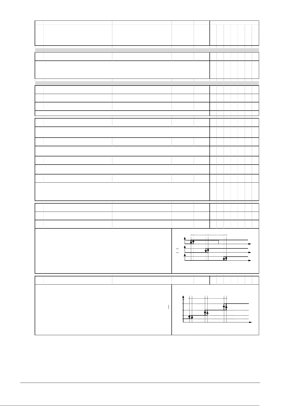
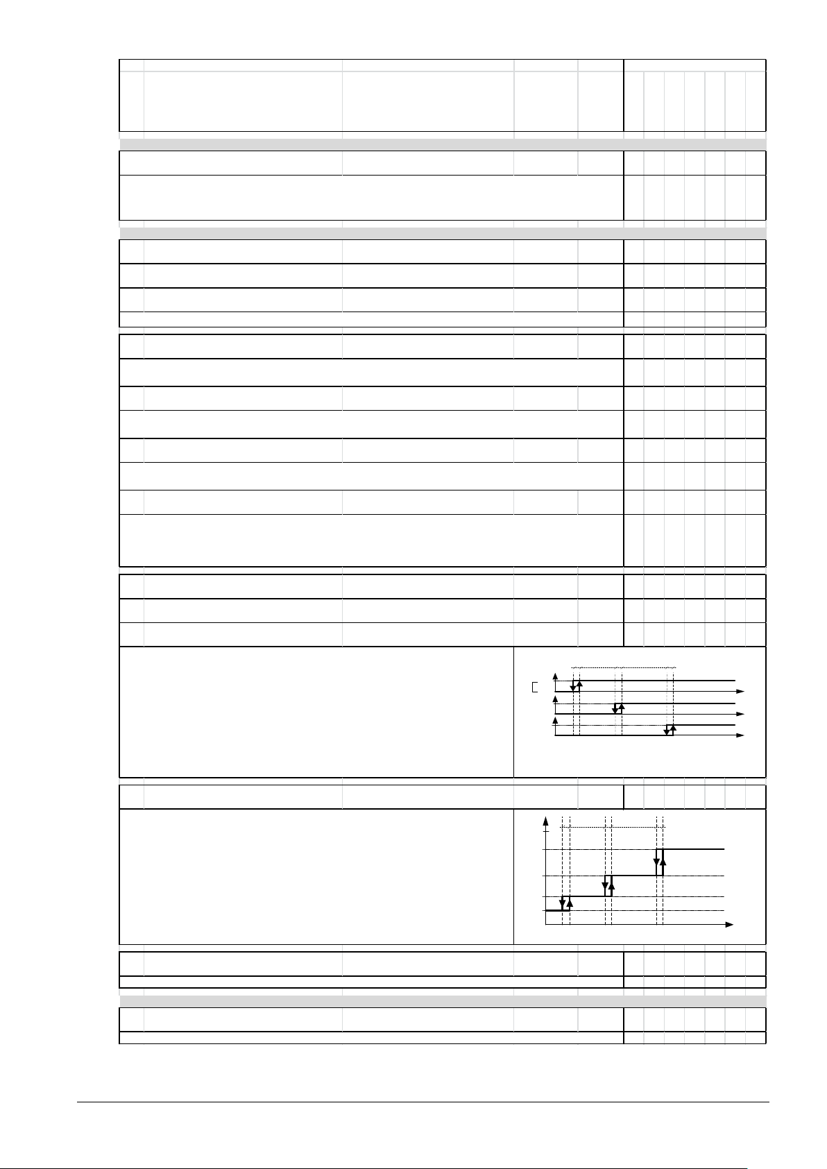
The stage belonging to positioning signal r.h. is switched on if room humidity overrides a
switching point r.h. The positioning signal r.h. is switched off again for room humidity <
switching r.h. - hysteresis .
The positioning signal configured for the stage is outputted if room humidity overrides a
switching point r.h. The positioning signal once again outputs the value of the next smaller
stage, for room humidity < s witching r.h. - Hysteresis.
Devices
Off
Pos. Signal stage 3
Pos. signal stage 2
Pos.signal stage1
On
[ppm CO2]
[% r.H.]
1411D01
Swithing
point stufe
1
Switching
point 2
Switching
point 3
Hysteresis
On
On
Off
Off
[ppm CO2]
[% r.H.]
[%]
Pos. Sig. Stage 0
Pos. signal stage 1
Pos. signal stage 2
Pos., signal
modulating
Pos. signal stage 3
Hysteresis
1411D02
Switching
point
stage 1
Switching
point
stage 2
Switching
point
stage 3
28 / 46
Siemens Wall-mounted sensors and room operator units for KNX/ETS and KNX/ACS CM2N1602en_05
Building Technologies ETS engineering 2018-09-14
Page 29
Obj. Object name Function Type / Le ngth Fl a gs
QMX3.P30
QMX3.P40
QMX3.P70
QMX3.P34
QMX3.P74
QMX3.P02
QMX3.P37
Room air quality sens or
38
CO
2
concentration [ppm ] CO
2
-Concentration in the room in ppm
9.008
2 bytes
CRWU
X X
Room air quality control
39
Switching point CO
2
- stage 1 CO
2
concentration in ppm
9.008
2 bytes
CRWU
X X X X X X X
40
Switching point CO
2
- stage 2 CO
2
concentration in ppm
9.008
2 bytes
CRWU
X X X X X X X
41
Switching point CO
2
- stage 3 CO
2
concentration in ppm
9.008
2 bytes
CRWU
X X X X X X X
42
Control value CO
2
cont. - m anual setp. Setpoint in ppm
5.001
1 byte
CRW
U
X X X X X X X
43
Control value CO
2
cont. - m anual mode Manual/Auto mode
1.003
1 bit
CRW
U
X X X X X X X
44 Enable room air quality controller On/Off
1.003
1 bit
CRWU
X X X X X X X
45 Override room air quality controller Ventilation (Boost) on/off
1.003
1 bit
CRWU
X X X X X X X
46
Control value CO
2
stage 1 - on/off 1 = On / 0 = Off
1.001
1 bit
CRT
X X X X X X X
47
Control value CO
2
stage 2 - on/off 1 = On / 0 = Off
1.001
1 bit
CRT
X X X X X X X
48
Control value CO
2
stage 3 - on/off 1 = On / 0 = Off
1.001
1 bit
CRT
X X X X X X X
49
Control value CO2 - cont 0-100%
5.001
1 byte
CRT
X X X X X X X
50
Control value CO2 / r.h. m ax.- cont. 0 to 100%
5.001
1 byte
CRT
X X X X X X X
QMX3.P70 Air qua lity LED indicator
51 Air quality: Enable LED indication 1 = On / 0 = Off
1.003
1 bit
CRWU
X
This object outputs the greater value for obj. 36 and obj. 49.
This object switches on and off the LED display on the QMX3.P70.
The positioning signal CO
2
belonging to the stage is switched on if the CO
2
concentration
exceeds the switching point CO
2
. The positioning signal CO
2
is switched off again for CO
2
concentration < switching point CO
2
- hys teresis.
The positioning signal configured to the state is outputted if CO
2
concentration exceeds a
switching point CO2. The positioning signal once again outputs the value of the next smaller
stage, CO2 concentration < switching point CO
2
- hys teresis.
Provides the CO
2
value from the integrated sens or.
Units with display: Must be placed in a group address to display operation/s ymbol display.
External CO
2
room sens or, see object 73
Changing over to the m anual mode perm its receipt of a m anual setpoint (Obj. 42) for the modulating positioning signal
(Obj. 49). Otherwis e, the configured positioning signals for the applicable stage are outputted.
All controller outputs are s witched off upon receipt of "Controller off".
The controller remains disabled until "Controller on" is received. The default value is controller on = 1.
For controller override, the s tage defined in the parameter "Stage is overridden" is enabled. Objects 46, 47, 48 assume
only the value "1=On" for the corresponding object; the other two objects the value "0 = Off". The modulating positioning
signal (obj. 49) outputs the value configured for the applicable stage.
Override has the highest priority. The default state is "Normal".
The configured default switching points apply as long as no value is received from the bus.
In manual mode (obj. 43, 1=Manual), a setpoint is received via this object and outputted directly as modulating positioning
signal (object 49).
Devices
Off
Pos. signal stage 3
Pos. Signal stage 2
Pos. signal stage 1
On
[ppm CO2]
[% r.H.]
1411D01
Switching
point
stage 1
Switching
point
stage 2
Switching
point
stage 3
Hysteresis
On
On
Off
Off
[ppm CO2]
[% r.H.]
[%]
Pos. Signal stage 0
Pos. Signal stage 1
Pos. Signal stage 2
Pos. signal mod.
Pos. Signal stage 3
Hysteresis
1411D02
Switching
point 1
Switching
point 2
Switching
point 3
Building Technologies ETS engineering 2018-09-14
Siemens Wall-mounted sensors and room operator units for KNX/ETS and KNX/ACS CM2N1602en_05
29 / 46
Page 30
Obj. Object name Function Type / Length Fl a g s
QMX3.P30
QMX3.P40
QMX3.P70
QMX3.P34
QMX3.P74
QMX3.P02
QMX3.P37
HMI displays and ope ration of value s a nd functions
53 Outs ide tem perature [°C] Display outs ide tem perature (°C)
9.001
2 bytes
CWU
X X X
55 Room temperature: Setpoint abs olute [°C]
9.001
2 bytes
CRWTU
X X X
56 Room temperature: Setpoint relative [K]
9.002
2 bytes
CWTA
X X X
58 Room operating mode: Preselection
20.102
1 byte
CRWTU
X X X
62 Window State
1.019
1 bit
CWU
X X X
63 Presencen button
1.001
1 bit
CRWTU
X X X
65 Fan speed: Pres election [%]
5.001
1 byte
CRWTU
X X X
66 Fan operation (0 = Auto / 1 = Manual) (0=Auto / 1=Manual)
1.003
1 bit
CRWTU
X X X
67 Fan speed [%]
5.001
1 byte
CWU
X X X
68 Controller mode (heating/cooling/off)
20.105
1 byte
CWU
X X X
69 Outs ide relative hum idity [%]
9.007
2 bytes
CWU
X X X
70 Room relative hum idity [%] % r.h.
9.007
2 bytes
CWU
X X
71 Room relative hum idity: Setpoint [%] % r.h .
9.007
2 bytes
CRWTU
X X X
73
Room CO2 concentration [ppm] 0 - 2000 ppm / symbol / text
9.008
2 bytes
CWU
X X
74
Room CO2 concentration: Setpoint [ppm] ppm
9.008
2 bytes
CRWTU
X X X
75 HVAC operation: Lock
1.011
1 bit
CRWU
X X X
Lock or enable all 8 operating buttons for the display via the bus.
The following symbol is dis played: A locked lock.
The buttons for lighting, blinds, and scenes are always enabled (QMX3.P37 and QMX3.P02).
Object 65 dis plays the fan speed that can be changed on the display or bus .
Obj. 66 displays the fan operating mode that can be changed on the display or bus.
Obj. 67 displays the actual fan speed as reported to the bus by the actuator/controller.
Units with display: Objects must be placed in a group addres s to display s ymbols .
Displays present controller state (heating or cooling) with symbols .
No symbol is dis played in the off state.
Units with display: Must be placed in a group address to display sym bols.
External outside temperature sensor value
Units with display: Must be placed in a group address to display the value.
Comfort setting that can be edited on the dis play
Units with display: Must be placed in a group address to display the value.
Displays the room operating mode that can be changed on the display (Auto-Comfort-Precomfort-Eco-Protection).
The present operating m ode is dis played in AUTO mode.
Units with display: Must be placed in a group address to display the value.
This object displays the state of a window contact for disenabled PID control.
For enabled PID control, see objects 18, 19, 20, 21.
Display and manual entry on display for occupancy and non-occupancy.
Units with display: Must be placed in a group address to display sym bols.
Displays the value of an external room CO
2
sensor on the display.
Units with display: Must be placed in a group address to display the values.
Note: The value of the internal room CO2 sensor is communicated via object 38; QMX3.P74
Display and operate the room CO2 concentration setpoint on the display.
Units with display: Must be placed in a group address to display the values.
Overrides s witching point CO
2
- stage 1 (object 26).
These objects display values from external sens ors (room/outside) on the display.
Units with display: Must be placed in a group address to display the values.
Note: The internal humidity sens or value is comm unicated via object 25; QMX3.P74.
Display and operate the room hum idity s etpoint on the display.
Units with display: Must be placed in a group address to display the values.
This overrides switching point r.h. - stage 1 (object 26).
Devices
30 / 46
Siemens Wall-mounted sensors and room operator units for KNX/ETS and KNX/ACS CM2N1602en_05
Building Technologies ETS engineering 2018-09-14
Page 31

Obj. Object name Function Type / Le ngth Fl a g s
QMX3.P30
QMX3.P40
QMX3.P70
QMX3.P34
QMX3.P74
QMX3.P02
QMX3.P37
Function button pair , button 1
80 Button A1: switching on / off
1.001
1 bit
CWT
X X
81 Button A1: send value
5.001
1 byte
CT
X X
82 Button A1, 2nd obj.: s witching on / off
1.001
1 bit
CWT
X X
83 Button A1: send value 2
5.001
1 byte
CT
X X
84 Button A1: switching on / off
1.001
1 bit
CWT
X X
85 Button A1: dimming brighter / darker
3.007
4 bit
CT
X X
86 Button A1: blind up / down
1.008
1 bit
CT
X X
87 Button A1: slats stop / open / close
1.007
1 bit
CT
X X
88 Button A1: 8-bit scene recall / save
18.001
1 byte
CT
X X
89 Status LED A1 on / off
1.001
1 bit
CRWU
X X
Function button pair , button 2
90 Button A2: switching on / off
1.001
1 bit
CWT
X X
91 Button A2: send value
5.001
1 byte
CT
X X
92 Button A2, 2nd obj.: s witching on / off
1.001
1 bit
CWT
X X
93 Button A2: send value 2
5.001
1 byte
CT
X X
94 Button A2: switching on / off
1.001
1 bit
CWT
X X
95 Button A2: dimming brighter / darker
3.007
4 bit
CT
X X
96 Button A2: blind up / down
1.008
1 bit
CT
X X
97 Button A2: slats stop / open / close
1.007
1 bit
CT
X X
98 Button A2: 8-bit scene recall / save
18.001
1 byte
CT
X X
99 Status LED A2 on / off
1.001
1 bit
CRWU
X X
Function button pair 2, button 1
100 Button B1: switching on / off
1.001
1 bit
CWT
X X
101 Button B1: send value
5.001
1 byte
CT
X X
102 Button B1, 2nd obj.: switching on / off
1.001
1 bit
CWT
X X
103 Button B1: send value 2
5.001
1 byte
CT
X X
104 Button B1: switching on / off
1.001
1 bit
CWT
X X
105 Button B1: dimm ing brighter / darker
3.007
4 bit
CT
X X
106 Button B1: blind up / down
1.008
1 bit
CT
X X
107 Button B1: slats s top / open / close
1.007
1 bit
CT
X X
108 Button B1: 8-bit scene recall / s ave
18.001
1 byte
CT
X X
109 Status LED B1 on / off
1.001
1 bit
CRWU
X X
Devices
Siemens Wall-mounted sensors and room operator units for KNX/ETS and KNX/ACS CM2N1602en_05
Building Technologies ETS engineering 2018-09-14
31 / 46
Page 32

Obj. Object name Function Type / Le ngth Fl a gs
QMX3.P30
QMX3.P40
QMX3.P70
QMX3.P34
QMX3.P74
QMX3.P02
QMX3.P37
Function button pair 2, button 2
110 Button B2: switching on / off
1.001
1 bit
CWT
X X
111 Button B2: send value
5.001
1 byte
CT
X X
112 Button B2, 2nd obj.: switching on / off
1.001
1 bit
CWT
X X
113 Button B2: send value 2
5.001
1 byte
CT
X X
114 Button B2: switching on / off
1.001
1 bit
CWT
X X
115 Button B2: dimm ing brighter / darker
3.007
4 bit
CT
X X
116 Button B2: blind up / down
1.008
1 bit
CT
X X
117 Button B2: slats s top / open / close
1.007
1 bit
CT
X X
118 Button B2: 8-bit scene recall / s ave
18.001
1 byte
CT
X X
119 Status LED B2 on / off
1.001
1 bit
CRWU
X X
Function button pair 3, button 1
120 Button C1: switching on / off
1.001
1 bit
CWT
X X
121 Button C1: send value
5.001
1 byte
CT
X X
122 Button C1, 2nd obj.: switching on / off
1.001
1 bit
CWT
X X
123 Button C1: send value 2
5.001
1 byte
CT
X X
124 Button C1: switching on / off
1.001
1 bit
CWT
X X
125 Button C1: dimm ing brighter / darker
3.007
4 bit
CT
X X
126 Button C1: blind up / down
1.008
1 bit
CT
X X
127 Button C1: slats s top / open / close
1.007
1 bit
CT
X X
128 Button C1: 8-bit scene recall / save
18.001
1 byte
CT
X X
129 Status LED C1 on / off
1.001
1 bit
CRWU
X X
Function button pair 3, button 2
130 Button C2: switching on / off
1.001
1 bit
CWT
X X
131 Button C2: send value
5.001
1 byte
CT
X X
132 Button C2, 2nd obj.: switching on / off
1.001
1 bit
CWT
X X
133 Button C2: send value 2
5.001
1 byte
CT
X X
134 Button C2: switching on / off
1.001
1 bit
CWT
X X
135 Button C2: dimm ing brighter / darker
3.007
4 bit
CT
X X
136 Button C2: blind up / down
1.008
1 bit
CT
X X
137 Button C2: slats s top / open / close
1.007
1 bit
CT
X X
138 Button C2: 8-bit scene recall / save
18.001
1 byte
CT
X X
139 Status LED C2 on / off
1.001
1 bit
CRWU
X X
Devices
32 / 46
Siemens Wall-mounted sensors and room operator units for KNX/ETS and KNX/ACS CM2N1602en_05
Building Technologies ETS engineering 2018-09-14
Page 33

Obj. Object name Function Type / Le ngth Fl a gs
QMX3.P30
QMX3.P40
QMX3.P70
QMX3.P34
QMX3.P74
QMX3.P02
QMX3.P37
Function button pair 4, button 1
140 Button D1: switching on / off
1.001
1 bit
CWT
X X
141 Button D1: send value
5.001
1 byte
CT
X X
142 Button D1, 2nd obj.: switching on / off
1.001
1 bit
CWT
X X
143 Button D1: send value 2
5.001
1 byte
CT
X X
144 Button D1: switching on / off
1.001
1 bit
CWT
X X
145 Button D1: dimm ing brighter / darker
3.007
4 bit
CT
X X
146 Button D1: blind up / down
1.008
1 bit
CT
X X
147 Button D1: slats s top / open / close
1.007
1 bit
CT
X X
148 Button D1: 8-bit scene recall / save
18.001
1 byte
CT
X X
149 Status LED D1 on / off
1.001
1 bit
CRWU
X X
Function button pair 4, button 2
150 Button D2: switching on / off
1.001
1 bit
CWT
X X
151 Button D2: send value
5.001
1 byte
CT
X X
152 Button D2, 2nd obj.: switching on / off
1.001
1 bit
CWT
X X
153 Button D2: send value 2
5.001
1 byte
CT
X X
154 Button D2: switching on / off
1.001
1 bit
CWT
X X
155 Button D2: dimm ing brighter / darker
3.007
4 bit
CT
X X
156 Button D2: blind up / down
1.008
1 bit
CT
X X
157 Button D2: slats s top / open / close
1.007
1 bit
CT
X X
158 Button D2: 8-bit scene recall / save
18.001
1 byte
CT
X X
159 Status LED D2 on / off
1.001
1 bit
CRWU
X X
Devices
Note
ommunication object no. 3 "Enable room temperature controller" is currently not
C
operable.
Siemens Wall-mounted sensors and room operator units for KNX/ETS and KNX/ACS CM2N1602en_05
Building Technologies ETS engineering 2018-09-14
33 / 46
Page 34

5.4 Room operator unit visualization and
Object no.
QMX3.P34 QMX3.P74
QMX3.P37 1
Room temperature
Displays the value of the internal room temperature sensor
X X X
setpoint absolute
Protection).
63
Occupancy: Button
X X X
(heating/cooling/off)
Off: No symbol is displayed.
18...21
Window state
Displays the symbol "Open window" (only during active PID control).
X X X
The value can also be received via bus when adjusted on another device.
67
Fan (%)
Displays the actual fan speed as reported to the bus by the actuator/controller.
X X X
25
Room humidity
Provides the value of the internal CO2 sensor to the bus.
X
38
CO2 concentration
Provides the value of the internal room humidity sensor to the bus.
X
Setpoint
communication objects:
53
Outside air temperature
Displays the value of an external outside temperature sensor.
X X X
69
Outside humidity
Displays the value of an external outside humidity sensor.
X X X
70
Room humidity
Displays the value of an external room humidity sensor.
X
X
concentration
Note
The appropriate communication objects must be placed in the group address
after parameterization to display internal functions on the room operator unit.
Name Description
operation
Room temperature,
55
Room temperature,
56
setpoint relative
Room operating mode,
58
preselection
Comfort mode, timer
17
button
Control mode
68
65 Fan, default value (%)
Fan mode:
66
(Auto-Manual)
Room humidity:
71
Setpoint
CO2 concentration:
74
Displays the Comfort setpoint that can be changed on the display.
Displays the room operating mode that can be changed on the display (Auto-ComfortPreComfort-Eco-Protection).
The present state is displayed in AUTO mode (Auto-Comfort-PreComfort-Eco-
Object 17 activates comfort extension. The extension period can be configured. OR ...
... Object 63 activates the display and manual entry for occupancy or non-occupancy.
Displays the symbols for the present control mode.
Displays the fan speed that can be changed on the display.
Displays the fan operating mode that can be changed on the display. The value can
also be received via bus when adjusted on another device.
Displays the Comfort setpoint that can be changed on the display.
Displays the CO2 setpoint that can be changed on the display.
Other important group addresses for operation and display on room operator units via
X X X
X X X
X X X
X X X
X X X
X X X
X X X
X X X
X X X
Room CO2
73
Displays the value of an external room CO2 sensor.
W
hen the absolute setpoint is displayed, only the heating setpoint is shown on the
display.
34 / 46
Siemens Wall-mounted sensors and room operator units for KNX/ETS and KNX/ACS CM2N1602en_05
Building Technologies ETS engineering 2018-09-14
X X
Page 35
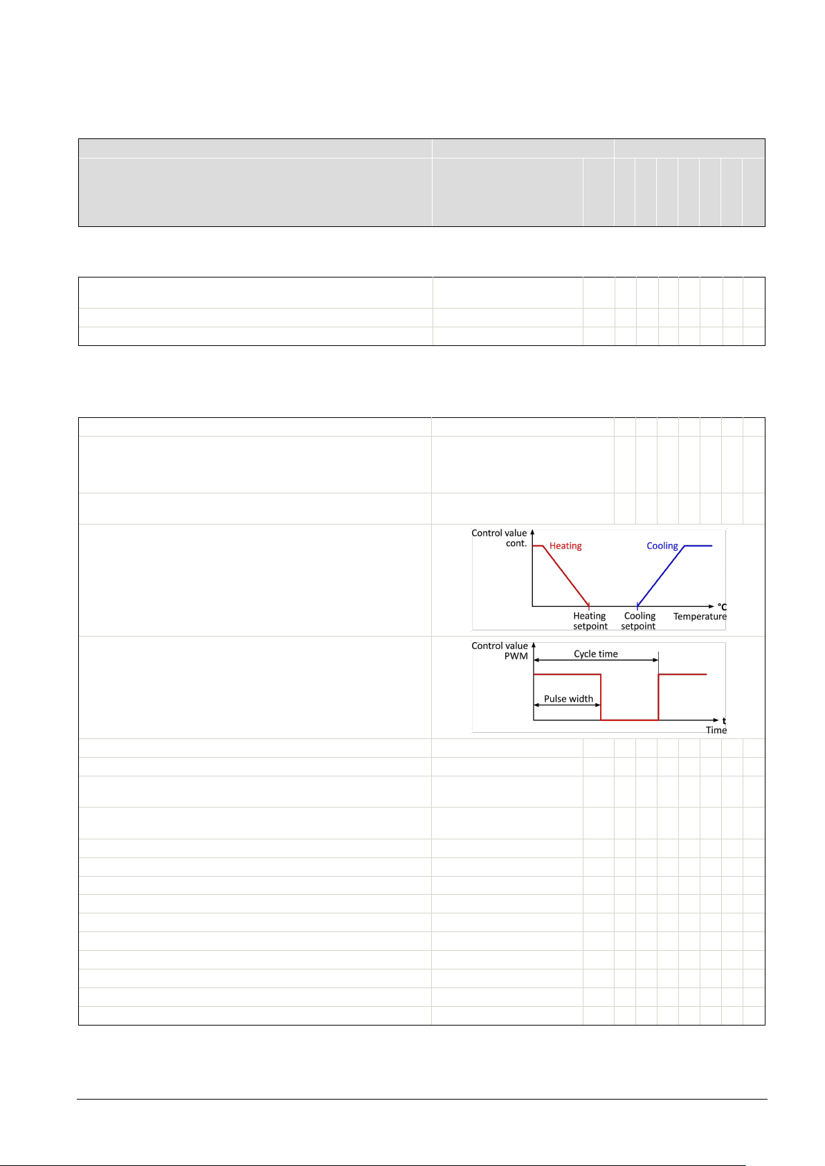
5.5 ETS parameter description
Designation
Values
Type
Unit QMX3.P30 QMX3.P40 QMX3.P70
QMX3.P34 QMX3.P74
QMX3.P37 QMX3.P02
(0 °C)
Room temperature: Send following change by
0.1…2.5 °C (0.1 °C)
K
X X X X X X X
(2 min)
X X X X X X X
Activate room temperature control
yes; no
X X X X X X X
Floor heating fast
Floor cooling
(21.0)
X X X X X X X
Default cooling setpoint
5…40 (24.0)
°C
X X X X X X X
1;2;3...30;45;60
Protection heating setpoint
5…40 (12.0)
°C
X X X X X X X
Economy heating setpoint
5…40 (15.0)
°C
X X X X X X X
X X X X X X X
Comfort heating setpoint
5…40 (21.0)
°C
X X X X X X X
X X X X X X X
Precomfort cooling setpoint
5…40 (28.0)
°C
X X X X X X X
X X X X X X X
Protection cooling setpoint
5…40 (40.0)
°C
X X X X X X X
Comfort extension time
5…120 (30)
min
X X X X X X X
Number of window status inputs
0…4
X X X X X X X
Factory settings are in brackets
Communication objects available in ETS
when function is enabled
Range
(Default)
5.5.1 Room temperature sensor
Room temperature: Sensor correction –5…+5 °C
Room temperature: Send cyclically after
n 0.1 steps
i
1…60
K
min
5.5.2 Room temperature control
To display this section, enable the option “Activate room temperature control” in Device
Heating type* Radiator heating slow
Cooling type
Parameters heating / cooling type allow for adapting the controller to
the type of heating / cooling. In addition, the controller features two
control algorithms: one for continuous mode (0..100%) and one for
PWM mode (On/Off). The mode is selected via parameter "Control
value type". The control value type is identical for all operating modes.
In continuous mode, the associated PWM output is "On" at
continuous control value ≠ 0.
(Radiator heating fast)
Floor heating slow
(Chilled ceiling)
X X X X X X X
X X X X X X X
X X X X X X X
In PWM mode, cycle time and pulse width are adapted to the type of
heating / cooling, the setpoint, and the measured room temperature.
The min. cycle time is 12 minutes, the min. pulse width is 4 minutes.
The continuous control value issues 0% or 100% in this operating
mode.
Default heating setpoint
Control value type
Send cyclically after Do not send cyclically
Precomfort heating setpoint 5…40 (19.0) °C
Comfort cooling setpoint 5…40 (24.0) °C
Economy cooling setpoint 5…40 (35.0) °C
5…40
(PWM)
Continuous 0…100%
°C
min
X X X X X X X
X X X X X X X
Siemens Wall-mounted sensors and room operator units for KNX/ETS and KNX/ACS CM2N1602en_05
Building Technologies ETS engineering 2018-09-14
35 / 46
Page 36

*
Heating type
Xp
TiN
TiV
Nz
SD
Radiator heating slow
2 K
5400s
450s
0,1K
0.8K
Radiator heating fast
2 K
3600s
540s
0,1K
0.8K
Floor heating slow
2 K
7200s
540s
0,1K
0.8K
Floor heating fast
2 K
5400s
540s
0,1K
0.8K
PID parameter set for the cooling sequence
Cooling type
Xp
TiN
TiV
Nz
SD
Chilled ceiling
2 K
5400s
450s
0,1K
0.8K
Note
PID parameter set for the heating sequence
Floor cooling 2 K 5400s 540s 0,1K 0.8K
egardless of the setting of the control signal type "PWM" or "continuous", all 4
R
objects are switched on. The option "Do not send cyclically" is not operable for the
moment.
36 / 46
Siemens Wall-mounted sensors and room operator units for KNX/ETS and KNX/ACS CM2N1602en_05
Building Technologies ETS engineering 2018-09-14
Page 37
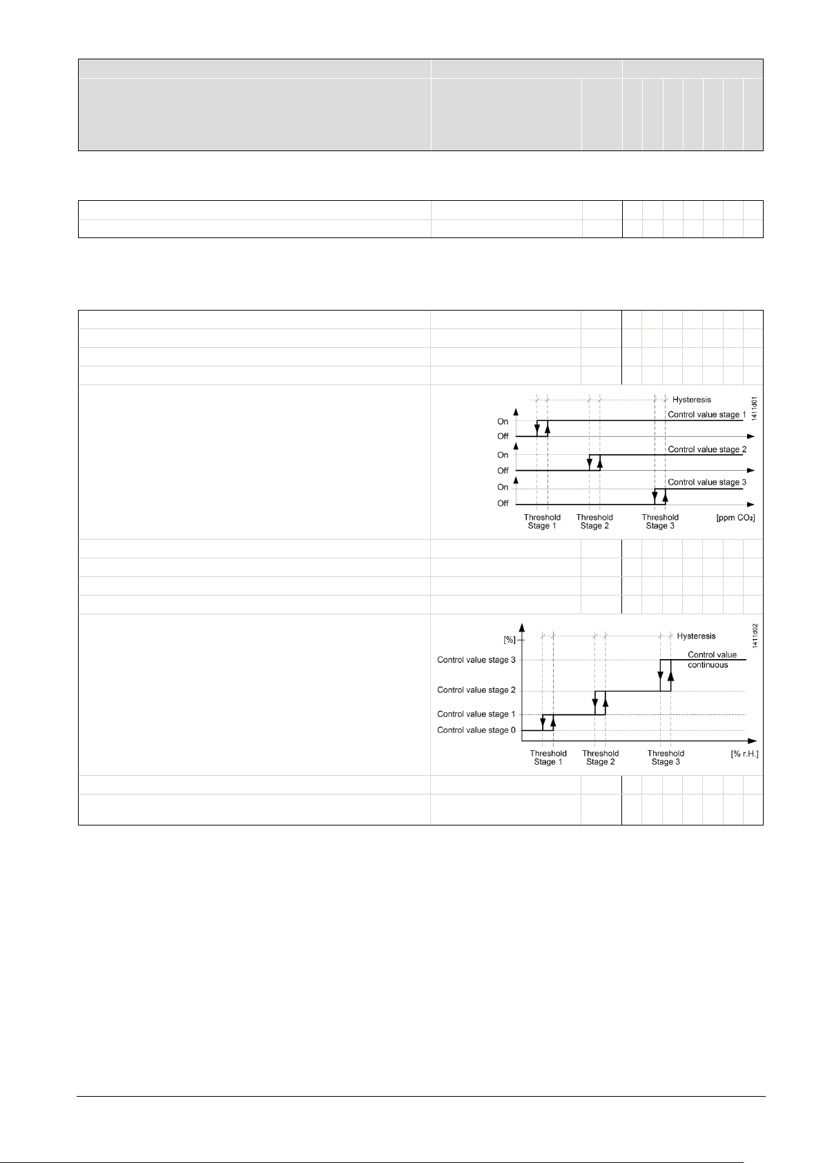
Designation
Values
Type
Visible parameter name in ETS Range
Unit QMX3.P30 QMX3.P40
QMX3.P70
QMX3.P34 QMX3.P74
QMX3.P37 QMX3.P02
Humidity: Send following change by
2; 3; 4; 5; 7; 10 (2%)
%r.h.
X X X
X X X
Default switching point stage 1 (%r.h.)
0…100 (40)
%r.h.
X X X X X X X
Default switching point stage 2 (%r.h.)
0…100 (70)
%r.h.
X X X X X X X
Default switching point stage 3 (%r.h.)
0…100 (90)
%r.h.
X X X X X X X
X X X X X X X
Control value stage 0 (%)
0…100 (0)
%
X X X X X X X
Control value stage 1 (%) (>stage 0)
0…100 (35)
%
X X X X X X X
Control value stage 2 (%) (>stage 1)
0…100 (70)
%
X X X X X X X
Control value stage 3 (%) (>stage 2)
0…100 (100)
%
X X X X X X X
Stage when overridden
0;1;2;3 (3)
X X X X X X X
1;2;3...30;45;60 (15 min)
(Default)
5.5.3 Room relative humidity sensor
Humidity: Send cyclically after 1; 2…45; 60 (15 min) min
5.5.4 Room relative humidity control
To display this section, enable the option “Activate room humidity control” in Device
Hysteresis 2;3;4;5;7;10 (5%) %r.h.
If room humidity exceeds a switching point r.h., the control value r.h.
for the respective stage is switched on.
Control value r.h. is switched off again when room humidity
< switching point r.h. – hysteresis.
If room humidity exceeds switching point r.h., the control value
parameterized for this stage is issued.
The control value again issues the next lower stage value when room
humidity < switching point r.h. – hysteresis.
Send cyclically after
Do not send cyclically
min.
X X X X X X X
Siemens Wall-mounted sensors and room operator units for KNX/ETS and KNX/ACS CM2N1602en_05
Building Technologies ETS engineering 2018-09-14
37 / 46
Page 38
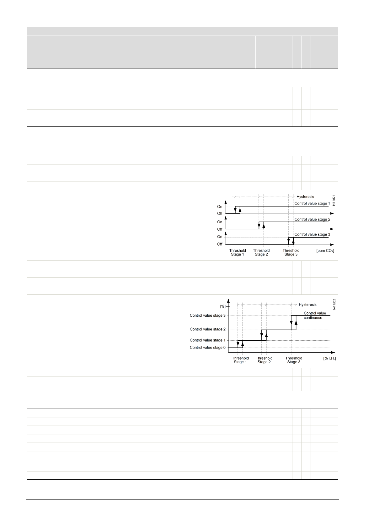
Designation
Values
Type
Visible parameter name in ETS Range
Unit QMX3.P30
QMX3.P40
QMX3.P70
QMX3.P34
QMX3.P74
QMX3.P37 QMX3.P02
(10ppm)
CO2 concentr.: Sensor correction (ppm)
-500…+500 (0 ppm)
ppm
X
X
CO2 concentr.: Send cyclically after
1;2;3…30;45;60 (15 min)
min
X
X
CO2 concentr.: Altitude above sea level (m)
0…5000 (0 m)
min.
X
X
Default switching point stage 1 (ppm)
400…2000 (800)
ppm
X X X X X X X
Default switching point stage 2 (ppm)
400…2000 (1000)
ppm
X X X X X X X
X X X X X X X
Hysteresis
50…500 (100)
ppm
X X X X X X X
Control value stage 0 (%)
0…100 (0)
%
X X X X X X X
Control value stage 1 (%) (>stage 0)
0…100 (35)
%
X X X X X X X
Control value stage 2 (%) (>stage 1)
0…100 (70)
%
X X X X X X X
Control value stage 3 (%) (>stage 2)
0…100 (100)
%
X X X X X X X
Stage when overridden
0;1;2;3 (3)
X X X X X X X
X X X
Backlight idle time
3…20 (15 s)
s
X X X
X X X
Active audio feedback (buttons)
yes; no (yes)
X X X
LED Brightness
0…100 (100)
%
X
X
Air quality
X X X
(Default)
5.5.5 Room air quality sensor
CO2 concentr.: Send following change by
5;10;20…500;750;1000
ppm
5.5.6 Room air quality control
To display this section, enable the option “Activate room air quality control” in Device
Default switching point stage 3 (ppm) 400…2000 (1500) ppm
If the CO2 concentration exceeds a switching point CO2, the control
value CO
is again switched off, if the CO
point CO
for the related stage is switched on. The control value CO2
2
– hysteresis.
2
concentration returns to < switching
2
X X
If the CO2 concentration exceeds a switching point CO2, the control
value CO
issues again the value of the next lower stage when CO
concentration < switching point CO
Send cyclically after
for the related stage is switched on. The control value
2
– hysteresis.
2
2
Do not send cyclically
1;2;3...30;45;60 (15 min)
5.5.7 Device display parameters
Backlight Level 0; 10;…100 (60%) %
Active unit set °C; °F (°C)
Display: Idle page
(HVAC operation and display)
Time to return to idle page (s) 3…120 (15 s) s
Temperature
Relative humidity
X X X X X X X
min.
X X X
38 / 46
Siemens Wall-mounted sensors and room operator units for KNX/ETS and KNX/ACS CM2N1602en_05
Building Technologies ETS engineering 2018-09-14
Page 39

Designation
Values
Type
Visible parameter name in ETS Range
Unit QMX3.P30 QMX3.P40
QMX3.P70
QMX3.P34 QMX3.P74
QMX3.P37 QMX3.P02
Room and Outside
Operation Room temperature setpoint
yes; (no)
X X X
Relative
X X X
Lower limit temp.setp.abs.
5…21 (18)
°C
X X X
X X X
Temp.setp.op.in steps of
0.1; 0.2; 0.5; 1.0; 2.0 (0.1)
°C
X X X
X X X
Max. positive temp.shift
0…+10 (+3)
K
X X X
Temperature shift in steps of
0.1; 0.2; 0.5; 1.0; 2.0 (0.5)
K
X X X
X X X
Operation Room Occupancy Mode
(yes); no
X X X
X X X
Display Heating/Cooling indication
yes; (no)
X X X
Operation fan Speed
yes; (no)
X X X
Variable speed
X X X
Maximum fan speed (variable speed)
100…0 (100%)
%
X X X
utside
Room and Outside
X X X
Max. rel. humidity setp. (%r.h.)
1…100 (95%
%r.h.
X X X
Rel. Hum. operation in steps of
1;2;5;10;20 (1%)
%
X X X
Change color green <--> yellow at (ppm)
400.2000 (1000)
ppm
X
Change color yellow <--> red at (ppm)
400…2000 (1500)
ppm
X
Can be de-/activated via bus
Note
(Default)
5.5.8 HVAC operation and display
Display Temperature visualization -----
(Room)
Outside
X X X
Room temperature setpoint type
Upper limit temp. Setp. Abs. 21…40 (26) °C
Max. negative temp.shift -10…0 (-3) K
Operation Room Operating Mode yes; (no)
Display Window state visualization yes; (no)
Fan type 1-speed
Minimum fan speed (variable speed) 0…100 (0%) %
egardless of whether the "Display Window state” is set to "Yes" or "No", all 4
R
Absolute; (
(3-speed)
)
communication objects for window contacts are always displayed
5.5.9 Operation and display: Relative humidity visualization
Display: Relative humidity visualization
----(Room)
O
X X X
X X X
Min. rel. humidity setp. (%r.h.) 0…99 (10%) %r.h.
5.5.10 Display on QMX3.P70 Air quality indication LED
Bus influence
Siemens Wall-mounted sensors and room operator units for KNX/ETS and KNX/ACS CM2N1602en_05
Building Technologies ETS engineering 2018-09-14
(No)
X
39 / 46
Page 40

5.5.11 Operation and display: air quality
Room
Text
Change symbol '+++' <-> '++-' at ppm
400…2000 (1000)
ppm
X X X
Change symbol '++-' <-> '+- -' at ppm
400…2000 (1500)
ppm
X X X
X X X
Change text 'Okay' <-> 'Poor' at ppm
400…2000 (1500)
ppm
X X X
Min. air quality setpoint (ppm)
0…2000 (400)
ppm
X X X
Max. air quality setpoint (ppm)
0…2000 (2000)
ppm
X X X
Air qual. operation in steps of
1;2;5….50;100;200 (100)
ppm
X X X
Individual buttons
LED response and parameterization
Send 8-Bit value]
object]
Send 8-Bit value])
[off, on (orientation light)]
Long button pressure via send 2nd object [No, Yes]
status object]
[Off, On (orientation light)]
1-button solar protection / blinds control
No LED display
Long button pressure [0.5 - 6.0s] move to end positions
release button.
Display: Air quality visualization
Display: Air quality visualization Numeric value (ppm)
Change text 'Good' <-> 'Okay' at ppm 400…2000 (1000) ppm
(-----)
(Symbol)
5.5.12 Operation of light, shading and scenes
Possible function assignment for buttons / button pairs
(8 individual buttons or 4 pairs of buttons).
Only QMX3.P02 and QMX3.P37
1-button switching/sending value
Edge Action rising edge [---, Off, On, At, Send percentage value,
LED display [object-independent, status
X X X
X X X
(Action falling edge [---, Off, On, At, Send percentage value,
Short button
pressure
Long button
pressure
1-button dimming
ction short/long button pressure [at/dim, On/brighter, Off/darker]
A
Long button pressure [0.5 - 6.0s] dimming value 0% or 100% ( status object) LED activation [Off/On,
ction short/long button pressure [stop/up/up, stop/close/down]
A
Scene Scene number [1…64] Selection of predefined scene (short
elease scene memory [Yes/Non]
R
(long button pressure [1 - 6s])
Action short button pressure [---, Off, On, At, Send
percentage value, Send 8-Bit value]
Action long button pressure[---, Off, On, At, Send percentage
value, Send 8-Bit value]
(Object independent) LED constant value
( Status object) LED activation [Off/On,
On/Off]
LED display [object-independent,
(Object independent) LED constant value
On/Off]
button pressure <0.5 s). LED On for 3 s
Memorize changed scene (long button
pressure >5 s).
LED flashes for 3 s. When off, user can
40 / 46
Siemens Wall-mounted sensors and room operator units for KNX/ETS and KNX/ACS CM2N1602en_05
Building Technologies ETS engineering 2018-09-14
Page 41
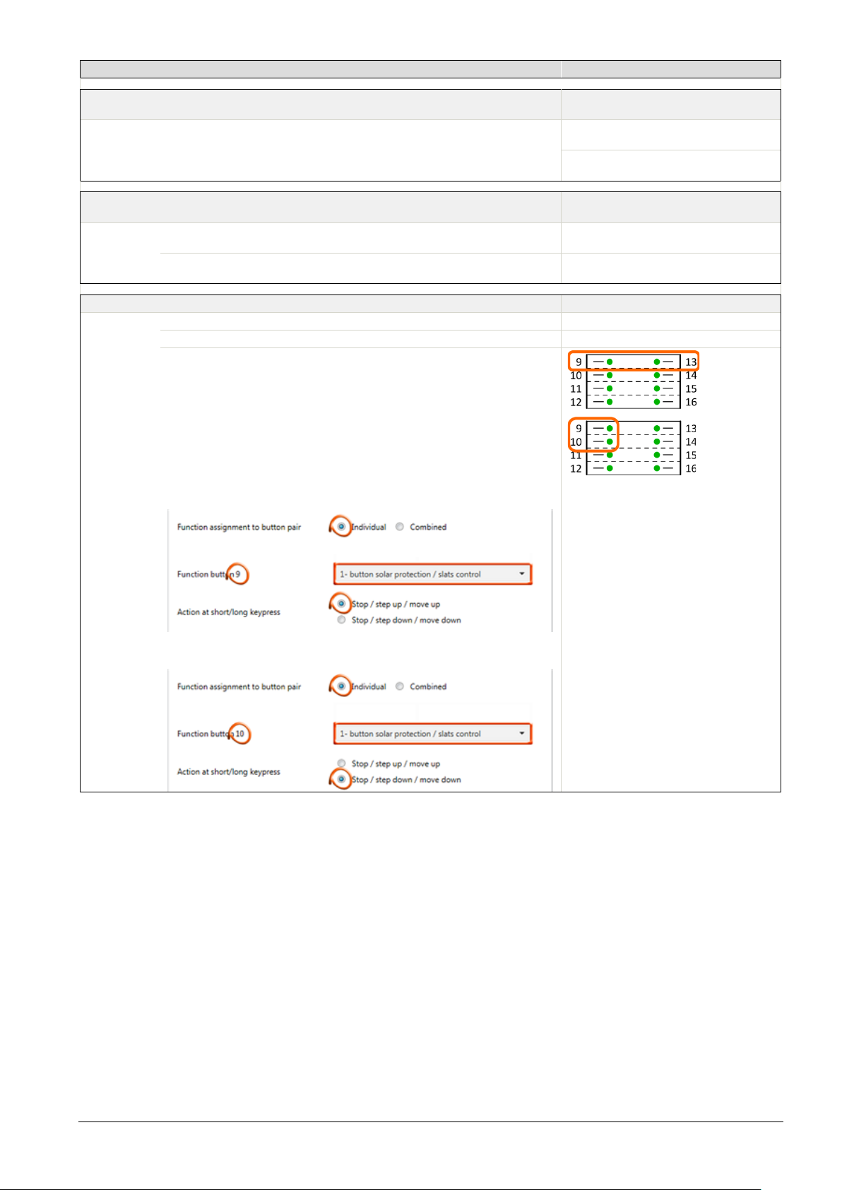
Combined / Button pairs
LED response and parameterization
2-button switching
status object]
On/Off]
status object]
[Off, On (orientation light)]
On/Off]
No LED display
Action button pair [left: step up/drive up, right: close/down]
—
Long button pressure [0.5 - 6.0s] move to end positions
—
Each of the desired buttons must be individually configured (individual).
Note
LED display [object-independent,
Action button pair [left Off, right On, right Off/left On] (Object independent) LED constant value
2-button dimming
ction button pair [left On/brighter, right Off/darker]
A
Long button pressure [0.5 - 6.0s] dimming value 0% or 100% (status object) LED activation [Off/On,
2-button solar protection / blinds control
Solar protection/blinds control can be individually modified for operation. The
factory setting is:
2 buttons next to one another, e.g. 9 Stop, step up, move up, and
If desired, this assignment can be modified in ETS, e.g. by assigning the
function to two buttons vertically. So that, for example
2 buttons on top of one another, e.g. 9 Stop, step up, move up, and
For button 9 (up) this means … :
[Off, On (orientation light)]
(status object) LED activation [Off/On,
LED A2 display [object-independent,
(Object independent) LED constant value
13 Stop, step down, move down
10 Stop, step down, move down
…
and for button 10 (down) … :
n all settings for buttons in which the time for a long key press can be set, if the
I
time of pressing the key is between 0.6 s and < "Long key press", no "Short key
press" telegram is sent.
Siemens Wall-mounted sensors and room operator units for KNX/ETS and KNX/ACS CM2N1602en_05
Building Technologies ETS engineering 2018-09-14
41 / 46
Page 42
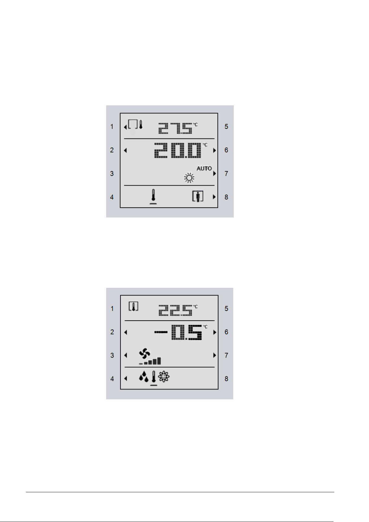
5.6 Examples for the operation of touch keys
Temperature and room
operating modes
Temperature,
fan control and
navigation
and display elements
In RTS, these functions are created as follows:
In the device view,
• activate or deactivate functions
• modify the default values if required
The objects that are now visible, must be connected to group addresses.
ey 1 Toggle the display between outdoor and indoor temperature
K
Keys 2 and 6 Room temperature setpoint adjustment (absolute)
Keys 3, 4 and 5 No function (no arrow symbols are displayed)
Key 7 Toggle the room operating mode (in Auto mode, the present operating mode is
displayed)
Key 8 Presence key, or Comfort extension
Key 1 No function, as only room temperature is displayed
Keys 2 and 6 Room temperature setpoint adjustment (relative)
Keys 3 and 7 Manual adjustment of fan speed
Key 4 Toggle the display pages between temperature, humidity, and CO
Keys 5 and 8 No function
2
42 / 46
Siemens Wall-mounted sensors and room operator units for KNX/ETS and KNX/ACS CM2N1602en_05
Building Technologies ETS engineering 2018-09-14
Page 43
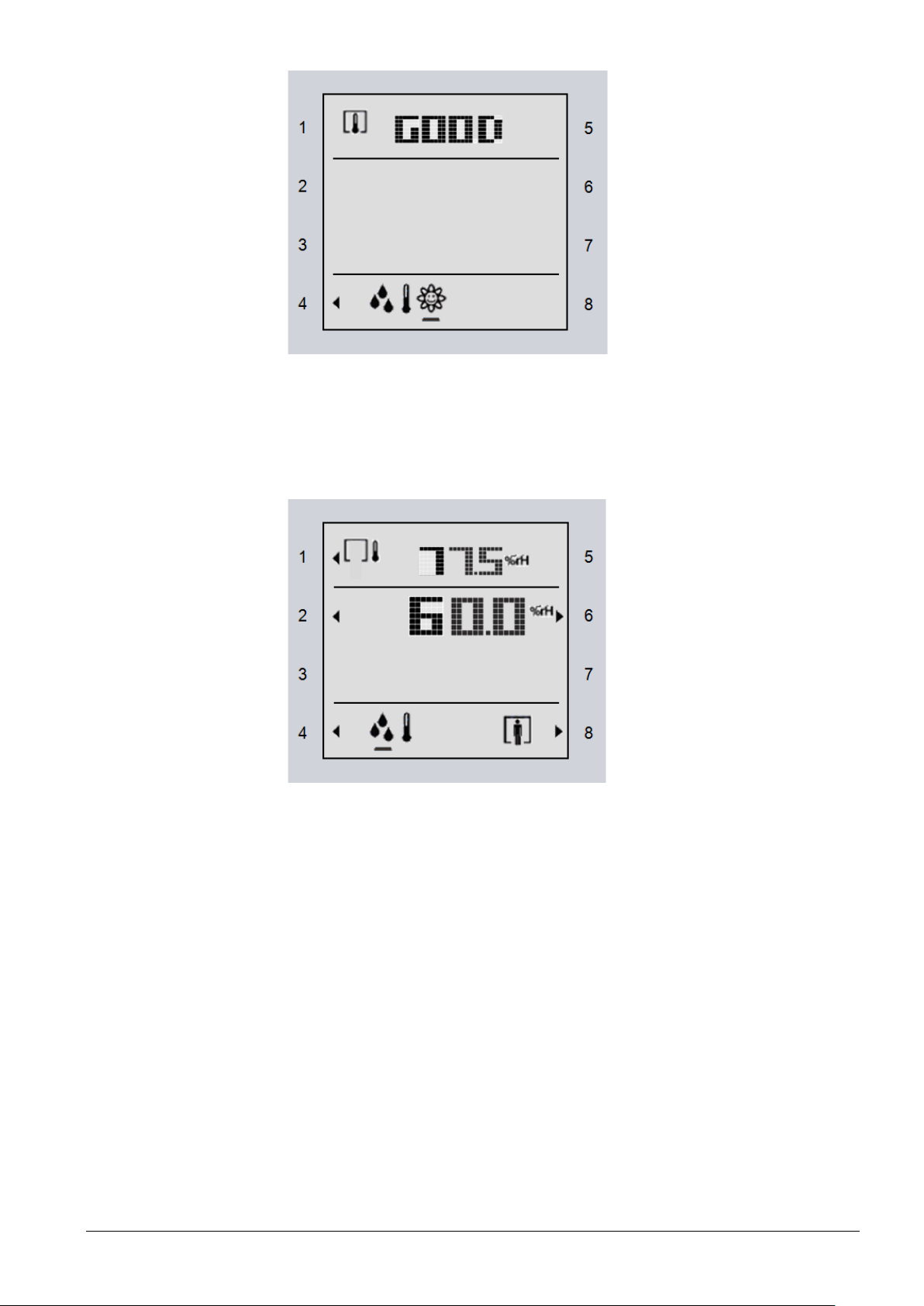
ey 1 No function, display of room air quality in text form
Air quality, CO2
Humidity and presence
K
GOOD, OKAY, or POOR
Keys 2, 3, 5, 6, 7 and 8 No function
Key 4 Toggle the display pages between temperature, humidity, and CO
K
ey 1 Toggle the display between outdoor and indoor humidity
Keys 2 and 6 Room humidity setpoint adjustment (absolute)
Keys 3, 5 and 7 No function
Key 4 Toggle the display pages between temperature and humidity
Key 8 Presence key, or Comfort extension
2
Siemens Wall-mounted sensors and room operator units for KNX/ETS and KNX/ACS CM2N1602en_05
Building Technologies ETS engineering 2018-09-14
43 / 46
Page 44

6 ACS engineering
Pushbutton actuation
Meaning
Short (< 0.5 s)
Switch over to programming mode or acknowledge display of a
connection test.
No functions are executed when the programming button is
pressed longer (> 0.5 s to 2 s).
Long (> 20 s)
Reset to factory settings.
LED indication
Meaning
Orange
Feedback on special mode.
Red
Device is in programming mode.
Room sensor QMX3, KNX LTE
connected
Variant 1 (recommended)
or
ACS790 version
Recommendation:
Keep the adhesive
address labels
Commissioning
prerequisites
Pushbuttons
LED status indication
Commissioning with
ACS
6.1 Engineering
Tool ACS790 is used for engineering with devices from the Synco 700 range. This
tool is documented in Service- and Operating software ACS790 [6].
For ACS790, version 8.23 or higher must be installed.
During room operator unit mounting, the address labels can be peeled off the
devices and stuck to a floor plan or similar to show the KNX IDs and the physical
location in one place.
After mounting/installation, the devices are detected after updating the ACS790
device list. The devices can be easily identified in the device list based on the
collected KNX IDs, and the physical addresses can be assigned as planned. As a
result, commissioning requires only very little effort.
6.2 Commissioning
Depending on the environment, both type and number of adjustable parameters
will vary. Prior to commissioning, all devices must be mounted as per the mounting
instructions [2] and connected to bus cabling. If available, pushbuttons and
external temperature sensors must also be connected to the device. Bus cabling
must be tested.
All other indication types are irrelevant for KNX LTE-Mode.
1. Select a room operator unit from the device list via the KNX ID
(KNX-IDs must be collected during mounting).
2. Double-click this line to open the "Address assignment" dialog.
44 / 46
Siemens Wall-mounted sensors and room operator units for KNX/ETS and KNX/ACS CM2N1602en_05
Building Technologies ACS engineering 2018-09-14
–Mode controllers, and operator units are
to power. Update first the ACS790 device list, then open.
Page 45

Variant 2
1. Set addressing mode for the room operator unit (briefly press button on
Enter a physical address and short description for the selected room
unit.
Close the "
Repeat these steps for all room
Then: Co
Commissioning with
ACS and ETS
ice LED is red).
dev
2. In the ACS790 device list, use "Addressing mode…" to select the
urrently active device Enter a physical address in the "Address
c
assignment" dialog Click "Write".
Address assignment“ dialog by clicking "Write…“.
operator units to be commissioned.
ntinue parameterization in ACS790.
he sensor can be operated in both communication modes at the same time.
T
To do this, commissioning with both ACS and ETS is required.
nly the sensor values (T, R.F., CO
O
) of the QMX3... devices can be used with
2
Synco ACS.
To activate them set the zones accordingly in ACS.
ACS settings and ETS settings do not influence each other.
operator
Siemens Wall-mounted sensors and room operator units for KNX/ETS and KNX/ACS CM2N1602en_05
Building Technologies ACS engineering 2018-09-14
45 / 46
Page 46

6.3 ACS Parameter description
Designation
Values
Description
Geographical zone (apartment)
---, 1...126
Geographical zone, apartment or room group
Geographical zone (room)
---, 1…63
Geographical zone, room
Geographical zone (subzone)
---, 1…15
Geographical zone, subzone
Designation
Values
Description
LTE transmission zone
---, 1…4095
Sending zone for KNX/ACS
Sensor correction
-5...+5K
0K
Correction of universal temperature sensor value
Designation
Values
Description
LTE transmission zone
---, 1…4095
Sending zone for KNX/ACS
Designation
Values
Description
LTE transmission zone
---, 1…4095
Sending zone for KNX/ACS
Altitude above sea level [m]
0…3000 m
0 m
Entry of altitude above sea level at measuring location to correct CO2 measured
value
Distributed by:
Siemens Switzerland Ltd.
Building Technologies Division
International Headquarters
Gubelstrasse 22
6301 Zug
Switzerland
Tel. +41 41
www.siemens.com/buildingtechnologies
Delivery and technical specifications subject to change
Factory settings are boldfaced.
6.3.1 Communication
6.3.2 Universal temperature sensor
in 0.1K steps
6.3.3 Room humidity sensor
6.3.4 Room air quality sensor
46 / 46
Siemens Wall-mounted sensors and room operator units for KNX/ETS and KNX/ACS CM2N1602en_05
Building Technologies ACS engineering 2018-09-14
-724 24 24
© Siemens Switzerland Ltd, 2013
 Loading...