

Page 1

Copyright 2005 by Siemens AG
A5E00409892-01
Product Information on the Reference Manual
Programmable Logic Controllers S7-300 Module Data Release 3
1 Position Decoder Module SM 338; POS-INPUT;
(6ES7338-4BC01-0AB0)
Order number
6ES7338-4BC01-0AB0
Characteristics
The position decoder module SM 338; POS-INPUT is distinguished by the
following features:
• 3 inputs for the connection of maximum three absolute value encoders (SSI)
and 2 digital inputs to freeze the encoder values
• Direct reaction possible to encoder values in moving systems
• Processing of acquired encoder values of the SM 338 in user program
• Supports clocked operation
• Type of encoder value acquisition (see chapter 1.1.2.1) can be selected:
– Free running
– Clocked
• 24 VDC rated input voltage
• Non-isolated against the CPU
• Fast mode selectable; with faster encoder recording and compressed
checkback interface
Fast mode is available as of SM 338; POS-INPUT firmware version V2.0.0 and
as of STEP 7 V5.3+SP2 selectable.
Page 2

2
Product Information on the Reference Manual Programmable Logic Controllers S7-300 Module Data Release 3
A5E00409892-01
Supported encoder types
The following encoder types are supported by the SM 338; POS-INPUT:
• Absolute value encoder (SSI) with 13-bit message length
• Absolute value encoder (SSI) with 21-bit message length
• Absolute value encoder (SSI) with 25-bit message length
Supported data formats
The SM 338; POS-INPUT supports the gray code and binary code data formats.
Firmware update
1)
You can use STEP 7 HW Config firmware update to load POS-INPUT in the
operating system memory of the SM 338 in order to extend the functionality and
trouble-shooting.
Note
The old firmware is deleted with the start of the firmware update. If the firmware
update is interrupted or canceled for any reason, the SM 338; POS-INPUT is no
longer functional. Restart the firmware update and wait until it has been
successfully completed.
1)
The function is only possible in distributed configuration if the header module (slave interface) supports the
necessary system services
Page 3

3
Product Information on the Reference Manual Programmable Logic Controllers S7-300 Module Data Release 3
A5E00409892-01
1.1 Synchronous Operation
Warning
The basics of synchronous operation are described in a separate manual.
Hardware requirements
For the synchronous operation of the SM 338, you require:
• CPU which supports clocked operation
• DP master which supports the equidistant bus cycle
• Slave interface (IM 153-x) which supports synchronous operation
Characteristics
Depending on the system parameterization, the SM 338 works in either
non-synchronous or synchronous mode.
In synchronous operation, the data exchange between DP master and SM 338 is
synchronous to the PROFIBUS DP cycle.
In synchronous operation all 16 bytes of the checkback interface are consistent.
If synchronicity is lost due to faults or failure or delay of Global Control (GC), the
SM 338 goes back into synchronous operation in the next cycle without error
response.
If synchronicity is lost, the checkback interface is not updated.
Page 4
4
Product Information on the Reference Manual Programmable Logic Controllers S7-300 Module Data Release 3
A5E00409892-01
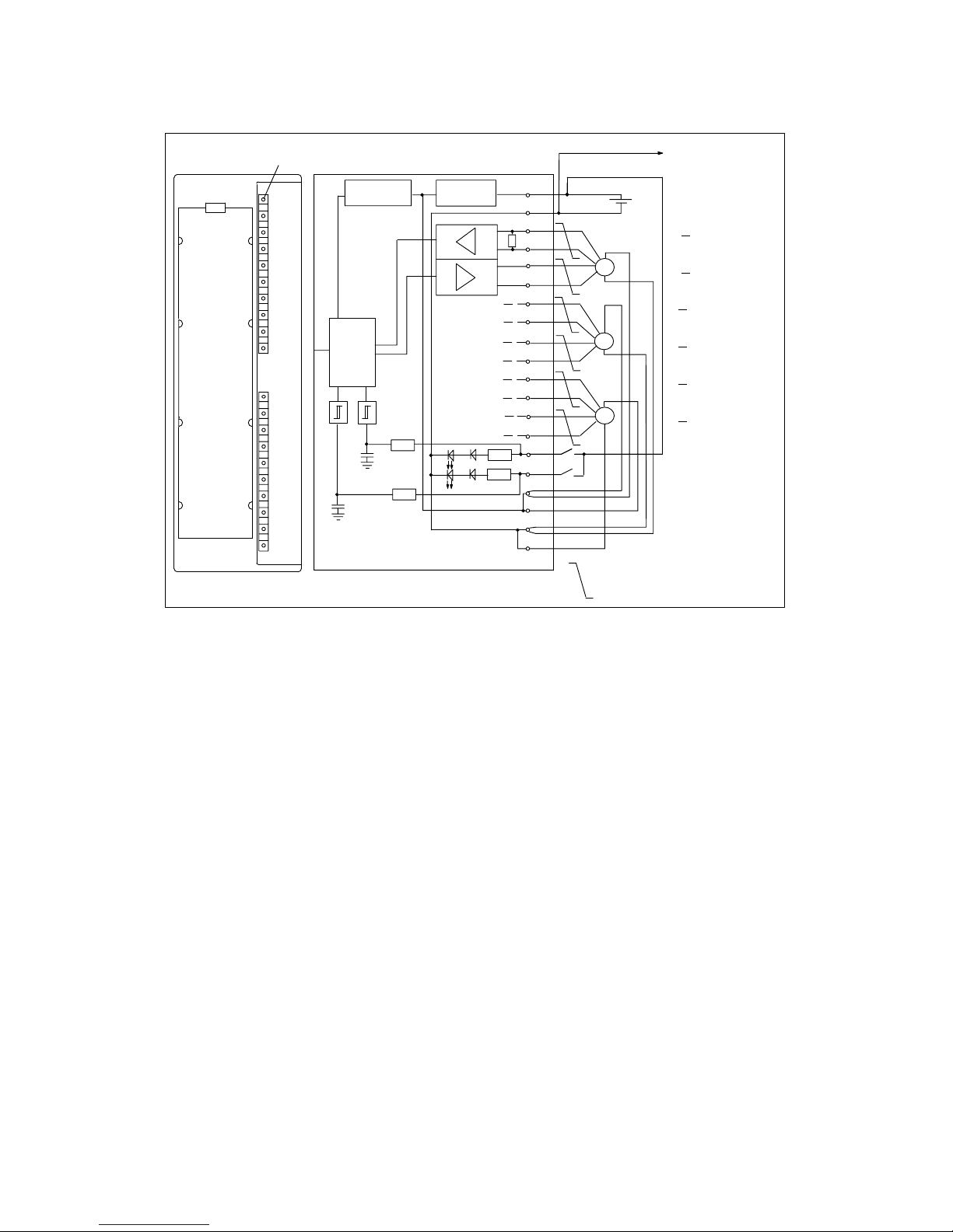
1.1.1 Terminal Connection Diagram and Block Diagram
Fault indicator – red
1
2
3
4
5
6
7
8
9
10
11
12
13
14
15
16
17
18
19
20
L+
24V
OD (Data)
OD (Data)
OC (Clock)
OC (Clock)
1D (Data)
1D (Data)
1C (Clock)
1C (Clock)
2D (Data)
2D (Data)
2C (Clock)
2C (Clock)
DI 0 (DigitalDI 1 input)
DC24V (encoder)
DC24V (encoder)
M (encoder)
M (encoder)
SSI
SSI
SSI
Short-circuit
protection
Voltage monitoring
SF
S7-300 Backplane bus
Logic
M
RS 422
Twisted pair cables
DI 0
DI 1
Connection to the
ground of the CPU
Figure 1-1 Module View and Block Diagram of the SM 338; POS-INPUT
Wiring rules
Please observe the following important rules of the wiring of the module:
• The ground of the encoder supply is connected non-isolated to the ground of
the CPU. Thus, connect pin 2 of the SM 338 (M) with low impedance with the
ground of the CPU.
• The encoder lines (pins 3 to 14) must be twisted pairs and shielded. Apply the
shield to both sides.
For the shield connection to the SM 338, use the shield connection element
(order number 6ES7390-5AA00-0AA0).
• If the output current (900 mA) of the encoder supply is exceeded, then you
must connect an external power supply.
Page 5

5
Product Information on the Reference Manual Programmable Logic Controllers S7-300 Module Data Release 3
A5E00409892-01
1.1.2 Functions of the SM 338; POS INPUT
1.1.2.1 Encoder value acquisition
The absolute value encoder transfers its encoder values in messages to the
SM 338. The transfer of the message is initiated by the SM 338.
• In non-synchronous operation, the encoder values are acquired while it is free
running.
• In synchronous operation the encoder values are acquired synchronized to the
PROFIBUS DP cycle at each Ti.
Free running encoder value acquisition
The SM 338 always initiates the transfer of a message after the end of the
parameterized monoflop time.
Asynchronous to these free running messages, the SM 338 processes the
acquired encoder values during the cycle of its updating rate (see Technical Data).
Thus, in the case of free running encoder value acquisition, encoder values of
different ages result. The difference between the maximum and minimum age is
the jitter (see Technical Data).
Synchronous encoder values acquisition
Synchronous encoder values acquisition is automatically set if, in the DP master
system, the equidistant bus cycle is activated and the DP Slave is synchronized to
the DP cycle.
The SM 338 initiates the transfer of a message in each PROFIBUS DP cycle
at the time Ti.
Synchronous to the PROFIBUS DP cycle, the SM 338 processes the transferred
encoder values.
Page 6

6
Product Information on the Reference Manual Programmable Logic Controllers S7-300 Module Data Release 3
A5E00409892-01
1.1.2.2 Gray/Dual Converter
In the Gray setting, the encoder values provided by the absolute value encoder in
gray code is converted into Dual code. In the Dual setting, encoder values
provided by the absolute value encoder remain unchanged.
Warning
If you have selected the Gray setting, the SM 338 always converts the entire
encoder value (13, 21, 25 bits). As a result, preceding special bits affect the
encoder values and following bits could be falsified under certain circumstances.
1.1.2.3 Transferred Encoder Value and Normalization
The transferred encoder value contains the encoder position of the absolute value
encoder. Depending on the encoder used, additional bits which are located before
and after the encoder position are also transferred in addition to the encoder
position.
So that the SM 338 can detect the encoder position, make the following settings:
• Normalization, places (0..12), or
• Normalization, units / revolution
Normalization, places
The normalization determines the position of the encoder values in the checkback
interface.
• If “Places” = 1, 2....12, this indicates that the following non relevant bits in the
encoder values are removed and the encoder value is right justified in the
address range (see following example).
• If “Places” = 0, this indicates that the following bits are retained and available
for evaluation.
This can be useful if you use an absolute value encoder which transfers
information in the following bits (see manufacturer information) and you want to
evaluate these (see also chapter 1.1.2.2).
Parameter units / revolution
A maximum of 13 bits are available for the units/revolution. According to the
“Places” data, the resulting number of units/revolution is automatically displayed.
Page 7

7
Product Information on the Reference Manual Programmable Logic Controllers S7-300 Module Data Release 3
A5E00409892-01
Example of normalization of an encoder value
You are using a single-turn encoder with 29 units= 512 units/ revolution
(resolution/360°).
In STEP 7 you have set the following parameters:
• Absolute encoder: 13 bits
• Normalization: 4 places
• Units / revolution: 512
Before the normalization: cyclically acquired encoder values 100
0
31
0000000000000000000000000
XXXX
00100
11
0000
Transferred bits
Relevant bits
After the normalization: encoder values 100
0
31
0000000000000000000000000 001001100000000
Relevant bits
Double data word
Double data word
Result: Bits 0 to 3 (4 places, marked with “x”) are omitted.
1.1.2.4 Freeze Function
The freeze function “freezes” the current encoder values of the SM 338. The
freeze function is coupled to the digital inputs DI 0 and DI 1 of the SM 338.
The freeze is triggered by an edge change (rising edge) on DI 0 or DI 1. A frozen
encoder value is identified by the bit 31 (output address) being set. With a digital
input you can freeze one, two or three encoder values.
You must switch on the freeze function, i.e. set the corresponding parameters in
STEP 7. The freeze function is not possible in fast mode.
The encoder values are retained until the freeze function is ended and can thus be
evaluated dependent on the event.
Page 8

8
Product Information on the Reference Manual Programmable Logic Controllers S7-300 Module Data Release 3
A5E00409892-01
Ending the freeze function
The freeze function must be ended at every encoder input. You acknowledge the
function in the user program by setting the bit 0, 1 or 2 depending on the channel
with the STEP 7-Operation T PAB “xyz” (for a program example,
see chapter 1.1.4).
After exiting, bit 31 of the corresponding encoder value is again deleted and the
encoder values are again updated. A renewed freezing of the encoder values is
again possible as soon as you have deleted the acknowledgment bit in the output
address of the module.
In synchronous operation the acknowledgment is processed at time To. From this
point in time a renewed freezing of the encoder values can take place via the
digital inputs.
Warning
The freeze function is automatically acknowledged if you newly parameterize the
corresponding channel with different parameters (see 1.1.3 chapter).
If the parameters remain identical, the freeze function remains unaffected.
1.1.3 SM 338; POS-INPUT Parameterization
You parameterize the SM 338; POS-INPUT with STEP 7. You must perform
parameter assignment in STOP mode of the CPU.
As soon as you have set all the parameters, download the parameters from the
programming device to the CPU. On a transition from STOP to ³ RUN mode, the
CPU then transfers the parameters to the SM 338.
The parameters cannot be changed by the user program.
Page 9

9
Product Information on the Reference Manual Programmable Logic Controllers S7-300 Module Data Release 3
A5E00409892-01
Parameters of the SM 338; POS-INPUT
You will find an overview of the parameters that you can set and their default
settings for the SM 338 in the table below.
The default settings apply if you have not performed parameter assignment in
STEP 7 (default setting bold).
Table 1-1 Parameters of the SM 338; POS-INPUT
Parameter
values Range Note
Enable
• Fast mode Yes/no
Release parameter.
Affects all 3 channels.
Enable
• Diagnosis interrupt Yes/no
Release parameter.
Affects all 3 channels.
Absolute value encoder
(SSI)
1)
none; 13 bits; 21 bits; 25 bits none: The encoder input is
switched off.
Code type
1)
Gray; Binary Code provided by encoder.
Baud rate
1) ,3)
125 kHz; 250 kHz; 500 kHz; 1 MHz Data transfer rate of the SSI
position decoder. Observe the
relationship between the cable
length and baud rate (see
Technical Data)
Monoflop time
1),2),3)
16 ms; 32 ms; 48 ms; 64 ms The monoflop time is the
minimum time interval between
2 SSI message frames.
The parameterized monoflop
time must always be greater than
the monoflop time of the absolute
value encoder.
Normalization
• Places
• Units / revolution
4)
0 to 12
2 to 8192
Normalizing right justifies the
encoder values of the encoder
absolute; non-relevant places are
discarded.
Switching on freeze off; 0; 1 Designation of the digital input
whose rising edge causes a
freezing of the encoder value.
1)
See technical data of the absolute value encoder
2)
The monoflop time is the time interval between 2 SSI message frames. The parameterized monoflop
time must be greater than the monoflop time of the absolute value encoder (see technical data of the
manufacturer). The time 2 (1 / baud rate) is added to the value parameterized in HW config. At a
baud rate of 125 kHz with a parameterized monoflop time of 16 ms, an effective monoflop time of 32 ms
is actually achieved.
3)
The following restriction applies to the monoflop time of the absolute value encoder:
(1 / baud rate) < Monoflop time of the absolute value encoder < 64 ms + 2 (1 / baud rate)
4)
to the power of two
Warning
Please note that in non synchronous operation the baud rate and the monoflop
time affect the accuracy and actuality of the encoder values.
In synchronous operation the baud rate and the monoflop time affect the accuracy
of the freeze function.
Page 10

10
Product Information on the Reference Manual Programmable Logic Controllers S7-300 Module Data Release 3
A5E00409892-01
1.1.4 SM 338; POS-INPUT Addressing
Data range for the encoder values
The inputs and outputs of the SM 338 are addressed as of the initial module
address. The input and output address is determined at the configuration of the
SM 338 in STEP 7.
Input Addresses
Table 1-2 SM 338; POS-INPUT: Input Addresses
Encoder input
Input address (from the configuration) + address offset
0 ”Initial module address”
1 ”Module start address” + 4 bytes address offset
2 ”Module start address” + 8 bytes address offset
Structure of the double data word in Standard Mode
For each encoder input the double data word is made up as follows:
Freeze
0 = encoder value is not frozen. The value is constantly updated.
1 = encoder value is frozen. The value remains constant until
acknowledgment.
25 bit sensor value in gray or binary code
31 024
Page 11

11
Product Information on the Reference Manual Programmable Logic Controllers S7-300 Module Data Release 3
A5E00409892-01
Structure of the double data word in Fast Mode
For each encoder input the double data word is made up as follows:
25 bit sensor value in gray or binary code
1 = Group error (sensor error, ext. auxiliary voltage error)
30 02427
Status digital input
1 = Parameter assignment error
1 = Ready for operation (checkback value valid)
In the double data word of channel 0, the status of the I0 is set in bit 27 (status
digital input) and in the double data word of channel 1, the status of the digital input
I1 is set.
The bit is always = 0 in the double data word of channel 2.
Output Address im Standard Mode
Acknowledging the freeze function:
Bit 0 = encoder input 0
Bit 1 = encoder input 1
Bit 2 = encoder input 2
Initial module address
07
Reading out data areas
You can read out the data areas in your user program with the STEP 7-Operation
L PED “xyz”.
Example of access to encoder values and use of the freeze function
You want to read out and evaluate the value of the encoder at the encoder inputs.
The module start address is 256.
No output data are supported in fast mode.
Page 12

12
Product Information on the Reference Manual Programmable Logic Controllers S7-300 Module Data Release 3
A5E00409892-01
AWL Explanation
L PED 256 //
T MD 100 //
U M 100.7 //
= M 99.0 //
L PED 260 //
T MD 104 //
U M 104.7 //
= M 99.1 //
L PED 264 //
T MD 108 //
U M 108.7 //
= M 99.2 //
L MB99//
T PAB 256 //
Read encoder value in the address range for
encoder input 0
Store encoder value in marker double word
Acquire and store freeze status for later
acknowledgment
Read encoder value in the address range for
encoder input 1
Store encoder value in marker double word
Acquire and store freeze status for later
acknowledgment
Read encoder value in the address range for
encoder input 2
Store encoder value in marker double word
Acquire and store freeze status for later
acknowledgment
Load and acknowledge freeze condition
(SM 338: output address 256)
Afterwards you can further process the encoder values from the marker range
MD 100, MD 104 and MD 108. The encoder value is contained in bits 0 to 30 of
the marker double word.
Page 13

13
Product Information on the Reference Manual Programmable Logic Controllers S7-300 Module Data Release 3
A5E00409892-01
1.1.5 Diagnosis of the SM 338; POS-INPUT
The SM 338 makes diagnostic messages available, i.e., all diagnostic messages
are always provided by the SM 338 without your assistance.
Actions following diagnostic message in STEP 7
Each diagnostic message leads to the following actions:
• The diagnostic message is entered in the diagnosis of the module and
forwarded to the CPU.
• The SF LED on the module lights.
• If you have programmed “Enable Diagnostic Interrupt” in STEP 7, a diagnostic
interrupt is triggered and OB 82 is called.
Reading out diagnostic messages
You can read out detailed diagnostic messages by means of SFCs in the user
program (refer to the Appendix “Diagnostic Data of Signal Modules”).
You can view the cause of the error in STEP 7, in the module diagnosis (refer to
online Help for STEP 7).
Diagnostic message via SF LED
The SM 338 indicate errors for you by means of their SF LED (group error LED).
The SF LED lights as soon as a diagnostic message is triggered by the SM 338. It
goes out when all errors have been rectified.
The group fault (SF) LED also lights up in case of external errors (short circuit of
encoder supply), independent of the operating status of the CPU (if power is on).
The SF LED lights up temporarily at startup during the self test of the SM 338.
Page 14

14
Product Information on the Reference Manual Programmable Logic Controllers S7-300 Module Data Release 3
A5E00409892-01
Diagnostic messages of the SM 338; POS INPUT
The table below gives an overview of the diagnostic messages for the SM 338.
Table 1-3 Diagnostic messages of the SM 338; POS INPUT
Diagnostics Message
LED Scope of the Diagno-
stics
Module problem SF Module
Internal malfunction SF Module
External malfunction SF Module
Channel error present SF Module
External auxiliary supply missing SF Module
Module not parameterized. SF Module
Wrong parameters SF Module
Channel information available SF Module
Time monitoring triggered SF Module
Channel error present SF Channel
(encoder input)
Configuring/parameter assignment error SF Channel
(encoder input)
External channel error (encoder fault) SF Channel
(encoder input)
Page 15

15
Product Information on the Reference Manual Programmable Logic Controllers S7-300 Module Data Release 3
A5E00409892-01
Causes of errors and remedial measures
Table 1-4 Diagnostics Messages of the SM 338, Causes of Errors and Remedial Measures
Diagnostics
Message
Possible Error Cause Remedy
Module fault An error detected by the module has
occurred.
Internal error Module has detected an error within
the automation system.
External error Module has detected an error outside
of the automation system.
Channel error present Indicates that only specific channels
are faulty .
External auxiliary
supply missing
The power supply L+ to the module is
missing
Feed supply L+
Module not
parameterized
Module requires information whether it
should work with parameters preset by
the system or with your parameters.
Message present after network active
until transfer of the parameters by the
CPU complete; parameterize module if
necessary.
Wrong parameters One parameter or the combination of
parameters is not plausible
Reassign module parameter
Channel information
present
Channel error present; module can
provide additional channel information.
Watchdog tripped Temporary high electromagnetic
interference
Eliminate interference
Channel error present An error detected by the module has
occurred at the encoder input.
Configuration /
parameterization error
Illegal parameter had been transferred
to module
Reassign module parameter
External channel error
(encoder error)
Broken wire in encoder cable, encoder
cable not connected or encoder
defective.
Check connected encoder
Page 16

16
Product Information on the Reference Manual Programmable Logic Controllers S7-300 Module Data Release 3
A5E00409892-01
1.1.6 Interrupts of the SM 338; POS INPUT
Introduction
In this Section, the interrupt behavior of the SM 338; POS-INPUT is described.
The SM 338 can trigger diagnostic interrupts.
The OBs and SFCs mentioned below can be found in the online Help for STEP 7,
where they are described in greater detail.
Enabling interrupts
The interrupts are not preset – in other words, they are inhibited without
appropriate parameter assignment. Assign parameters to the Interrupt Enable in
STEP 7 (refer to Section 1.1.3).
Diagnostic interrupt
If you have enabled diagnostic interrupts, then incoming active error events (initial
occurrence of the error) and departing error events (message after
troubleshooting) are reported by means of interrupts.
The CPU interrupts execution of the user program and processes the diagnostic
interrupt block (OB 82).
In the user program, you can call SFC 51 or SFC 59 in OB 82 to obtain more
detailed diagnostic information from the module.
The diagnostic information is consistent until such time as OB 82 is exited. When
OB 82 is exited, the diagnostic interrupt is acknowledged on the module.
Page 17

17
Product Information on the Reference Manual Programmable Logic Controllers S7-300 Module Data Release 3
A5E00409892-01
1.1.7 Technical Specifications of the 338; POS-INPUT
Dimensions and Weight
Dimensions B x H x T
(mm)
40 x 125 x 120
Weight Approx. 235 g
Voltages, Currents, Potentials
Rated load voltage L+
• Range
• Reverse polarity
protection
24 VDC
20.4 ... 28.8 V
No
Isolation no, only against shield
Permitted potential
difference
• between input
(M connection) and
central grounding point
of the CPU
1 VDC
Encoder supply
• Output voltage
• Output current
L+ –0.8 V
max. 900 mA, short
circuit–proof
Current dissipation
• From the backplane
bus
• From the load voltage
L+ (no load)
max. 160 mA
max. 10 mA
Power dissipation of the
module
typ. 3 W
Encoder inputs POS INPUT 0 to 2
Position decoding absolute
Difference signals for SSI
data and SSI clock
according to RS422
Data transfer rate and cable
length of absolute value
encoders (twisted pair and
shielded)
• 125 kHz max. 320 m
• 250 kHz max. 160 m
• 500 kHz max. 60 m
• 1 MHz max. 20 m
Message duration of the
SSI transmission
• 125 kHz
• 250 kHz
• 500 kHz
• 1 MHz
13 bits 21 bits 25 bits
112 ms 176 ms 208 ms
56 ms 88 ms 104 ms
28 ms 44 ms 52 ms
14 ms 22 ms 26 ms
Monoflop time
2
16 ms, 32 ms, 48 ms, 64 ms
Digital inputs DI 0, DI 1
Isolation no, only against shield
Input voltage 0-Signal: –3 V ... 5 V
1-Signal: 11 V ... 30.2 V
Input current 0-Signal: v2 mA
(quiescent current)
1-Signal: 9 mA (typ.)
Input delay 0 > 1: max. 300 ms
1 > 0: max. 300 ms
Maximum repeat frequency 1 kHz
Connection of a two–wire
BEROS, type 2
Possible
Shielded line length 600 m
Unshielded line length 32 m
Status, Interrupts, Diagnostics
Interrupts
• Diagnostic interrupt Parameters can be
assigned
Status display of digital
inputs
Group error/fault
LED (green)
LED (red)
Inaccuracy of the encoder value
Free running encoder value acquisition
(Standard Mode)
• Maximum age
1)
(2 × Message duration)
+ monoflop time
+ 580 ms
• Minimum age
1)
Message duration
+ 130 ms
• Jitter
Message duration
+ monoflop time
+ 450 ms
Update rate Evaluation of the message
every 450 ms
Free–wheeling sensor value detection (Fast Mode)
• Maximum age
1)
(2 × Message duration)
+ monoflop time
+ 400 ms
• Minimum age
1)
Message duration+
100 ms
• Jitter Message duration+
monoflop time + 360 ms
Update rate Evaluation of the message
every 360 ms
Synchronous encoder value acquisition
• Age Encoder value at time T
i
of
the current PROFIBUS DP
cycle
Page 18

18
Product Information on the Reference Manual Programmable Logic Controllers S7-300 Module Data Release 3
A5E00409892-01
Inaccuracy of the frozen encoder value (freeze)
Free running encoder value acquisition
• Maximum age
1)
(2 × Message duration)
+ monoflop time
+ 580 ms
• Minimum age
1)
Message duration
+ 130 ms
• Jitter
Message duration +
monoflop time + 450 ms
Synchronous encoder value acquisition
• Jitter
Max (message
durationn + param.
Monoflop time n)
n = 0, 1, 2, (Channel)
Isochrone time of the module
In Standard Mode TWE 850 ms
TWA 620 ms
ToiMin 90 ms
TDPMin 1620 ms
In Fast Mode TWE 700 ms
TWA 0 ms
ToiMin 0 ms
TDPMin 900 ms
1)
Age of the encoder values determined by the
transfer process and the processing
2)
The following restriction applies to the monoflop
time of the absolute value encoder:
(1 / baud rate) < Monoflop time of the absolute
value encoder < 64
ms + 2 x (1 / baud rate)
 Loading...