

Page 1

SiemensUrdaneta
POLYMOBIL III/Plus
Troubleshooting Guide
System
SP
Serial numbers 20,000 and higher
1018780010187803
Print No.:
Replaces: SPR8-125.840.10.03.02
SPR8-125.840.10.04.02
© Siemens
The reproduction, transmission or use
of this document or its contents is not
permitted without express written
authority. Offenders will be liable for
damages. All rights, including rights
created by patent grant or registration
of a utility model or design, are
reserved.
English
Doc. Gen. Date: 05.09
2007
Page 2

2 Revision / Disclaimer
1Revision / Disclaimer
Document revision level
The document corresponds to the version/revision level effective at the time of system
delivery. Revisions to hardcopy documentation are not automatically distributed.
Please contact your local Siemens office to order current revision levels.
Disclaimer
The installation and service of equipment described herein is to be performed by qualified
personnel who are employed by Siemens or one of its affiliates or who are otherwise authorized by Siemens or one of its affiliates to provide such services.
Assemblers and other persons who are not employed by or otherwise directly affiliated with
or authorized by Siemens or one of its affiliates are directed to contact one of the local
offices of Siemens or one of its affiliates before attempting installation or service procedures.
POLYMOBIL III/Plus SPR8-125.840.10.04.02 Siemens
05.09 CS SD SP/ CO
Page 2 of 104
Page 3

Table of Contents 3
0Table of Contents
1 _______ General ________________________________________________________ 6
Safety Notes, Notes and Symbols . . . . . . . . . . . . . . . . . . . . . . . . . . . . . . . . . . . . . . . . . . 6
Safety information and protective measures . . . . . . . . . . . . . . . . . . . . . . . . . . . . . . . . . . 7
Tools, measurement and auxiliary devices. . . . . . . . . . . . . . . . . . . . . . . . . . . . . . . . . . . 10
Cleaning . . . . . . . . . . . . . . . . . . . . . . . . . . . . . . . . . . . . . . . . . . . . . . . . . . . . . . . . . . . . . 11
2 _______ Overview______________________________________________________ 12
POLYMOBIL III . . . . . . . . . . . . . . . . . . . . . . . . . . . . . . . . . . . . . . . . . . . . . . . . . . . . . . . . 13
D916 . . . . . . . . . . . . . . . . . . . . . . . . . . . . . . . . . . . . . . . . . . . . . . . . . . . . . . . . . . . . . 13
D922, filament inverter, ON/OFF switching circuit . . . . . . . . . . . . . . . . . . . . . . . . . . 15
U1 power supply unit 5 V ± 5% / 15 V ± 10% . . . . . . . . . . . . . . . . . . . . . . . . . . . . . . 17
U2 power supply unit 12.5 V ± 10% . . . . . . . . . . . . . . . . . . . . . . . . . . . . . . . . . . . . . 17
D98 Display board . . . . . . . . . . . . . . . . . . . . . . . . . . . . . . . . . . . . . . . . . . . . . . . . . . 17
D1/ Measurement circuit . . . . . . . . . . . . . . . . . . . . . . . . . . . . . . . . . . . . . . . . . . . . . . 17
C1/ Inverter capacitor . . . . . . . . . . . . . . . . . . . . . . . . . . . . . . . . . . . . . . . . . . . . . . . . 17
Pre-load and discharge resistors . . . . . . . . . . . . . . . . . . . . . . . . . . . . . . . . . . . . . . . 17
Status of the LEDs (optimum condition) . . . . . . . . . . . . . . . . . . . . . . . . . . . . . . . . . . 17
POLYMOBIL Plus . . . . . . . . . . . . . . . . . . . . . . . . . . . . . . . . . . . . . . . . . . . . . . . . . . . . . . 19
D916 . . . . . . . . . . . . . . . . . . . . . . . . . . . . . . . . . . . . . . . . . . . . . . . . . . . . . . . . . . . . . 19
D927 . . . . . . . . . . . . . . . . . . . . . . . . . . . . . . . . . . . . . . . . . . . . . . . . . . . . . . . . . . . . . 22
U1 power supply unit 5 V ± 5% / 15 V ± 10% . . . . . . . . . . . . . . . . . . . . . . . . . . . . . . 23
U2 power supply unit 12.5 V ± 10% . . . . . . . . . . . . . . . . . . . . . . . . . . . . . . . . . . . . . 23
D952 capacitor charging circuit. . . . . . . . . . . . . . . . . . . . . . . . . . . . . . . . . . . . . . . . . 23
D971 (capacitor bank). . . . . . . . . . . . . . . . . . . . . . . . . . . . . . . . . . . . . . . . . . . . . . . . 24
D98 Display board . . . . . . . . . . . . . . . . . . . . . . . . . . . . . . . . . . . . . . . . . . . . . . . . . . 24
C1 main inverter capacitor . . . . . . . . . . . . . . . . . . . . . . . . . . . . . . . . . . . . . . . . . . . . 24
C2 . . . . . . . . . . . . . . . . . . . . . . . . . . . . . . . . . . . . . . . . . . . . . . . . . . . . . . . . . . . . . . 24
K22 switch-on relay. . . . . . . . . . . . . . . . . . . . . . . . . . . . . . . . . . . . . . . . . . . . . . . . . . 24
Discharge resistors . . . . . . . . . . . . . . . . . . . . . . . . . . . . . . . . . . . . . . . . . . . . . . . . . . 25
Status of the LEDs (optimum condition) . . . . . . . . . . . . . . . . . . . . . . . . . . . . . . . . . . 25
3 _______ Error Messages ________________________________________________ 26
POLYMOBIL III . . . . . . . . . . . . . . . . . . . . . . . . . . . . . . . . . . . . . . . . . . . . . . . . . . . . . . . . 26
Error 1 - Loss of the + 15 V dc . . . . . . . . . . . . . . . . . . . . . . . . . . . . . . . . . . . . . . . . . 26
Error 3 - Oil pressure rise or overheating of the tube . . . . . . . . . . . . . . . . . . . . . . . . 26
Error 4 - Static short circuit of the main inverter . . . . . . . . . . . . . . . . . . . . . . . . . . . . 27
Error 6 - IH heating measured < IH of preheating. . . . . . . . . . . . . . . . . . . . . . . . . . . 27
Error 7 - IH heating measured > IH allowed by software . . . . . . . . . . . . . . . . . . . . . 28
Error 8 - kV measured < > 0 in idle . . . . . . . . . . . . . . . . . . . . . . . . . . . . . . . . . . . . . . 28
Error 9 - mA measured < > 0 in idle . . . . . . . . . . . . . . . . . . . . . . . . . . . . . . . . . . . . . 28
Error 11 - Voltage too high in the capacitor bank . . . . . . . . . . . . . . . . . . . . . . . . . . . 29
Error 12 - Noise in the static short circuit signal in the heating inverter . . . . . . . . . . 29
Error 13 - Voltage in the capacitor bank is low during charge process . . . . . . . . . . . 30
Error 15 - Static short circuit, heating inverter . . . . . . . . . . . . . . . . . . . . . . . . . . . . . 30
Error 22 - short circuit, heating inverter . . . . . . . . . . . . . . . . . . . . . . . . . . . . . . . . . . 31
Error 23 - Tube current limitation. . . . . . . . . . . . . . . . . . . . . . . . . . . . . . . . . . . . . . . . 31
Error 25 - Preparation timeout . . . . . . . . . . . . . . . . . . . . . . . . . . . . . . . . . . . . . . . . . 32
Siemens SPR8-125.840.10.04.02 POLYMOBIL III/Plus
05.09 CS SD SP/ CO
Page 3 of 104
Page 4

4 Table of Contents
Error 31 - kV limit. . . . . . . . . . . . . . . . . . . . . . . . . . . . . . . . . . . . . . . . . . . . . . . . . . . . 32
Error 34 - Tube current limit . . . . . . . . . . . . . . . . . . . . . . . . . . . . . . . . . . . . . . . . . . . . 33
Error 35 - Short circuit in the main inverter . . . . . . . . . . . . . . . . . . . . . . . . . . . . . . . . 33
Error 36 - Short circuit in the heating inverter . . . . . . . . . . . . . . . . . . . . . . . . . . . . . . 34
Error 37 - Regulation failure in the kV loop . . . . . . . . . . . . . . . . . . . . . . . . . . . . . . . . 34
Error 38 – Regulation failure in the mA loop . . . . . . . . . . . . . . . . . . . . . . . . . . . . . . . 34
Error 39 - Exposure timeout . . . . . . . . . . . . . . . . . . . . . . . . . . . . . . . . . . . . . . . . . . . 35
Error 41 - The exposure has not finished . . . . . . . . . . . . . . . . . . . . . . . . . . . . . . . . . 35
Error 42 - Heating current limit . . . . . . . . . . . . . . . . . . . . . . . . . . . . . . . . . . . . . . . . . 35
Error 92 - RAM failure . . . . . . . . . . . . . . . . . . . . . . . . . . . . . . . . . . . . . . . . . . . . . . . . 35
Error 93 - Failure in the initial verification of the + 15 V DC. . . . . . . . . . . . . . . . . . . . 35
Error 94 - Difference between doubler signal and voltage level. . . . . . . . . . . . . . . . . 36
Error 95 - Precharge Error. . . . . . . . . . . . . . . . . . . . . . . . . . . . . . . . . . . . . . . . . . . . . 36
Error 96 - Failure of Channel D (KV_NOM) in A/D converter . . . . . . . . . . . . . . . . . . 36
Error 97 - Failure of Channel B (JR_NOM) in A/D converter. . . . . . . . . . . . . . . . . . . 36
Error 98 - Failure of Channel C (Ih_NOM) in A/D converter . . . . . . . . . . . . . . . . . . . 36
POLYMOBIL Plus . . . . . . . . . . . . . . . . . . . . . . . . . . . . . . . . . . . . . . . . . . . . . . . . . . . . . . 37
"Pause" error . . . . . . . . . . . . . . . . . . . . . . . . . . . . . . . . . . . . . . . . . . . . . . . . . . . . . . . 37
Error 1 - Loss of the + 15 V dc. . . . . . . . . . . . . . . . . . . . . . . . . . . . . . . . . . . . . . . . . . 37
Error 3 - Oil pressure rise or overheating of the tube . . . . . . . . . . . . . . . . . . . . . . . . 37
Error 4 - Static short circuit of the main inverter . . . . . . . . . . . . . . . . . . . . . . . . . . . . 38
Error 6 - IH heating measured < IH of preheating . . . . . . . . . . . . . . . . . . . . . . . . . . . 38
Error 7 - IH heating measured > IH allowed by software . . . . . . . . . . . . . . . . . . . . . . 38
Error 8 - kV measured < > 0 in idle . . . . . . . . . . . . . . . . . . . . . . . . . . . . . . . . . . . . . . 39
Error 9 - mA measured < > 0 in idle . . . . . . . . . . . . . . . . . . . . . . . . . . . . . . . . . . . . . 39
Error 11 - Voltage too high in the capacitor bank. . . . . . . . . . . . . . . . . . . . . . . . . . . . 39
Error 12 - Noise in the static short circuit signal in the heating inverter. . . . . . . . . . . 40
Error 13 - Voltage in the capacitor bank is low during charge process . . . . . . . . . . . 40
Error 15 - Static short circuit, heating inverter . . . . . . . . . . . . . . . . . . . . . . . . . . . . . . 41
Error 22 - Short circuit, heating inverter . . . . . . . . . . . . . . . . . . . . . . . . . . . . . . . . . . 41
Error 23 - Tube current limitation . . . . . . . . . . . . . . . . . . . . . . . . . . . . . . . . . . . . . . . . 42
Error 24 - The anode does not get up to its startup speed . . . . . . . . . . . . . . . . . . . . 42
Error 25 - Preparation timeout . . . . . . . . . . . . . . . . . . . . . . . . . . . . . . . . . . . . . . . . . . 42
Error 28 - Starter short circuit . . . . . . . . . . . . . . . . . . . . . . . . . . . . . . . . . . . . . . . . . . 43
Error 31 - kV limit. . . . . . . . . . . . . . . . . . . . . . . . . . . . . . . . . . . . . . . . . . . . . . . . . . . . 43
Error 34 - Tube current limit . . . . . . . . . . . . . . . . . . . . . . . . . . . . . . . . . . . . . . . . . . . . 44
Error 35 - Short circuit in the main inverter . . . . . . . . . . . . . . . . . . . . . . . . . . . . . . . . 44
Error 36 - Short circuit in the heating inverter . . . . . . . . . . . . . . . . . . . . . . . . . . . . . . 45
Error 37 - Regulation failure in the kV loop . . . . . . . . . . . . . . . . . . . . . . . . . . . . . . . . 45
Error 38 – Regulation failure in the mA loop . . . . . . . . . . . . . . . . . . . . . . . . . . . . . . . 45
Error 39 - Exposure timeout . . . . . . . . . . . . . . . . . . . . . . . . . . . . . . . . . . . . . . . . . . . 45
Error 41 - The exposure has not finished . . . . . . . . . . . . . . . . . . . . . . . . . . . . . . . . . 46
Error 42 - Heating current limit . . . . . . . . . . . . . . . . . . . . . . . . . . . . . . . . . . . . . . . . . 46
Error 92 - RAM failure . . . . . . . . . . . . . . . . . . . . . . . . . . . . . . . . . . . . . . . . . . . . . . . . 46
Error 93 - Failure in the initial verification of the + 15 V DC. . . . . . . . . . . . . . . . . . . . 46
Error 96 - Failure of Channel D (KV_NOM) in A/D converter . . . . . . . . . . . . . . . . . . 46
Error 97 - Failure of Channel B (JR_NOM) in A/D converter. . . . . . . . . . . . . . . . . . . 47
Error 98 - Failure of Channel C (Ih_NOM) in A/D converter . . . . . . . . . . . . . . . . . . . 47
4 _______ Service programs_______________________________________________ 48
General . . . . . . . . . . . . . . . . . . . . . . . . . . . . . . . . . . . . . . . . . . . . . . . . . . . . . . . . . . . . . . 48
POLYMOBIL III/Plus SPR8-125.840.10.04.02 Siemens
05.09 CS SD SP/ CO
Page 4 of 104
Page 5

Table of Contents 5
Activation of the service programs . . . . . . . . . . . . . . . . . . . . . . . . . . . . . . . . . . . . . . 48
POLYMOBIL III . . . . . . . . . . . . . . . . . . . . . . . . . . . . . . . . . . . . . . . . . . . . . . . . . . . . . . . . 49
Service programs . . . . . . . . . . . . . . . . . . . . . . . . . . . . . . . . . . . . . . . . . . . . . . . . . . . 49
POLYMOBIL Plus . . . . . . . . . . . . . . . . . . . . . . . . . . . . . . . . . . . . . . . . . . . . . . . . . . . . . . 54
Service programs . . . . . . . . . . . . . . . . . . . . . . . . . . . . . . . . . . . . . . . . . . . . . . . . . . . 54
5 _______ Measurements _________________________________________________ 59
POLYMOBIL Plus . . . . . . . . . . . . . . . . . . . . . . . . . . . . . . . . . . . . . . . . . . . . . . . . . . . . . . 59
High-voltage circuit . . . . . . . . . . . . . . . . . . . . . . . . . . . . . . . . . . . . . . . . . . . . . . . . . . 59
Filament heating circuit . . . . . . . . . . . . . . . . . . . . . . . . . . . . . . . . . . . . . . . . . . . . . . . 67
Line voltage. . . . . . . . . . . . . . . . . . . . . . . . . . . . . . . . . . . . . . . . . . . . . . . . . . . . . . . . 73
Measuring KV and JR . . . . . . . . . . . . . . . . . . . . . . . . . . . . . . . . . . . . . . . . . . . . . . . . 73
Capacitor charging circuit . . . . . . . . . . . . . . . . . . . . . . . . . . . . . . . . . . . . . . . . . . . . . 74
Rotating anode starter . . . . . . . . . . . . . . . . . . . . . . . . . . . . . . . . . . . . . . . . . . . . . . . 76
kV Control . . . . . . . . . . . . . . . . . . . . . . . . . . . . . . . . . . . . . . . . . . . . . . . . . . . . . . . . . 77
Testing the filament circuit. . . . . . . . . . . . . . . . . . . . . . . . . . . . . . . . . . . . . . . . . . . . . 81
Testing and setting the mAs counter. . . . . . . . . . . . . . . . . . . . . . . . . . . . . . . . . . . . . 86
Coincidence of light and radiation fields . . . . . . . . . . . . . . . . . . . . . . . . . . . . . . . . . . 87
POLYMOBIL III . . . . . . . . . . . . . . . . . . . . . . . . . . . . . . . . . . . . . . . . . . . . . . . . . . . . . . . . 90
Checking the maximum main inverter frequency . . . . . . . . . . . . . . . . . . . . . . . . . . . 90
Oscillating current measurement . . . . . . . . . . . . . . . . . . . . . . . . . . . . . . . . . . . . . . . 90
Checking the high-voltage kV
Checking the filament and tube current . . . . . . . . . . . . . . . . . . . . . . . . . . . . . . . . . . 93
Setting the maximum filament frequency . . . . . . . . . . . . . . . . . . . . . . . . . . . . . . . . . 95
Checking the tube current. . . . . . . . . . . . . . . . . . . . . . . . . . . . . . . . . . . . . . . . . . . . . 96
Checking the kV and tube current (IR) . . . . . . . . . . . . . . . . . . . . . . . . . . . . . . . . . . . 96
Checking the mAs values . . . . . . . . . . . . . . . . . . . . . . . . . . . . . . . . . . . . . . . . . . . . . 98
Adjusting the mAs . . . . . . . . . . . . . . . . . . . . . . . . . . . . . . . . . . . . . . . . . . . . . . . . . . . 98
Coincidence of light and radiation fields . . . . . . . . . . . . . . . . . . . . . . . . . . . . . . . . . . 99
NOM
and kV
. . . . . . . . . . . . . . . . . . . . . . . . . . . . . . 93
ACT
6 _______ Changes to previous version ____________________________________ 103
Siemens SPR8-125.840.10.04.02 POLYMOBIL III/Plus
05.09 CS SD SP/ CO
Page 5 of 104
Page 6
6 General
Safety Notes, Notes and Symbols 0
1- 1General
DANGER
WARNING
CAUTION
NOTICE
DANGER indicates an immediate danger that if disregarded
will cause death or serious physical injury.
¹
WARNING indicates a possible danger that if disregarded
can cause death or serious physical injury.
¹
CAUTION used with the safety alert icon indicates a possible
danger that if disregarded will or can lead to minor or moderate physical injury and/or damage to property.
¹
NOTICE used without the safety alert icon indicates a possible danger that if disregarded can or will lead to an undesirable outcome or state other than death, physical injury or
property damage.
¹
NOTE
NOTE is used to indicate information that explains the proper
way to use devices or to carry out a process, i.e., provides
pointers and tips.
X Warning about ionizing radiation or radioactive substances. Tests and adjustments that
must be performed with the radiation switched on are indicated by this radiation warning
icon.
V Dangerous electrical voltage > 25 VAC or > 60 VDC.
C Caution! General hazard warning.
E ESD: Warning about electrostatically sensitive components.
P Report icon. Used to indicate entries in certificates.
POLYMOBIL III/Plus SPR8-125.840.10.04.02 Siemens
05.09 CS SD SP/ CO
Page 6 of 104
Page 7
General 7
Safety information and protective measures 1.1
WARNING
WARNING
Risk of death, injury or material damage.
Strictly follow
- the product-specific safety information, the general safety
information in the document TD00-000.860.01... and the
safety information according to ARTD Part 2.
¹ Non-compliance can lead to death, injuries, or material
damage.
X-ray radiation!
When working on the system where radiation has to be
released, comply with all radiation protection directives and
the rules for radiation protection according to
ARTD-002.731.02.
¹ Non-compliance can lead to illnesses, irreversible
damage to body cells and to genetic make-up, severe
injuries, or death.
¹ Use available radiation protection devices.
¹ Wear radiation protection clothing (lead apron).
¹ Maintain the greatest possible distance from the radia-
tion source.
¹ Release radiation only if necessary.
¹ Set radiation activity as low as possible (low KV and
mAs values).
Siemens SPR8-125.840.10.04.02 POLYMOBIL III/Plus
05.09 CS SD SP/ CO
Page 7 of 104
Page 8

8 General
WARNING
POLYMOBIL Plus! (with X3 connected!)
To avoid electrical shock from components under voltage,
also be aware that:
The capacitor bank might still carry a charge. Do not attempt
to work on the system while this condition exists.
After switching off the system, approximately 450 VDC may
still be present in the system even after disconnecting the
line voltage plug. Within 10 minutes, this voltage will drop to
approximately 10 V.
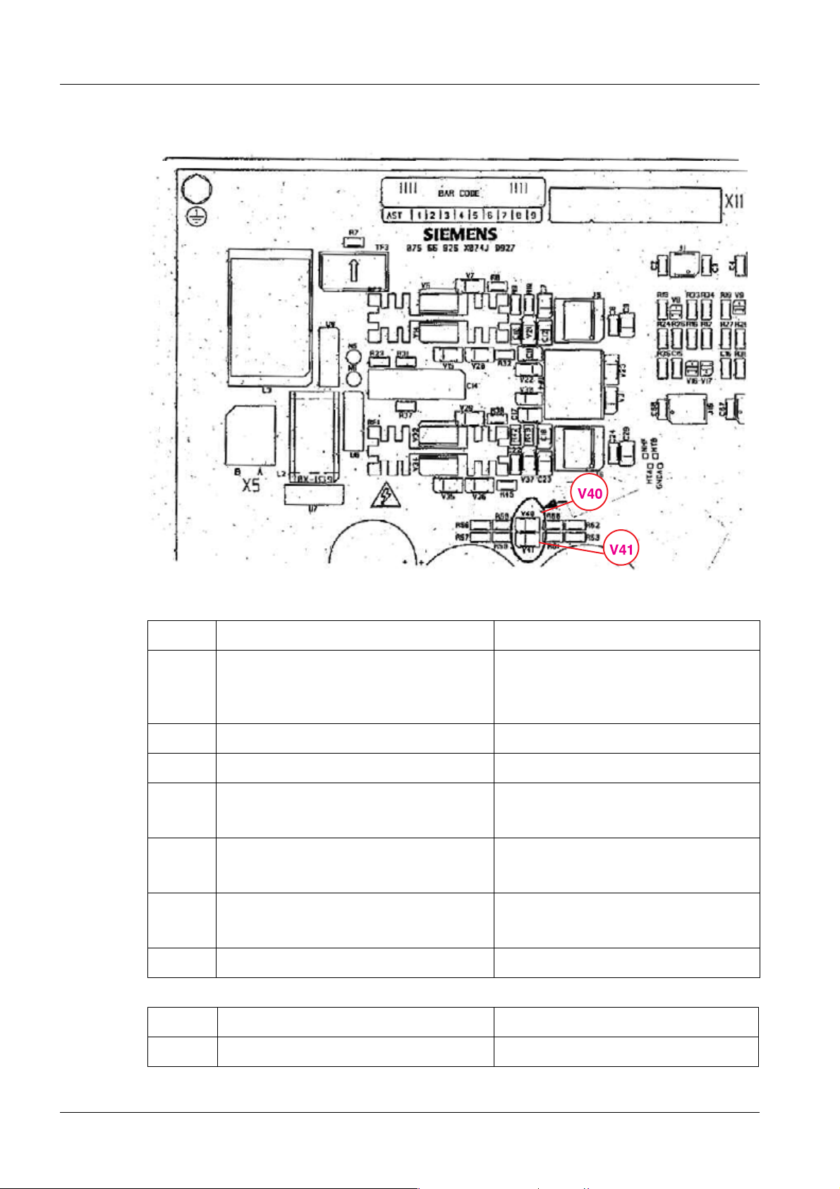
¹ Inspect LEDs V40 and V41 on D927, which is dis-
charged with the bank.
¹ Measure the voltage between the chassis and the right
side of F5 (D927) --> X3 connected!
¹ Before beginning any service work, wait until the volt-
age drops to approx. 10V within approx. 10 minutes;
the LEDs V1 to V10 on D 971 are then off (each of them
represents the voltage in one condenser).
¹ If one or more fuses on the D 971 have responded, high
voltage may still be present at the affected capacitor
even after a prolonged period of time.
¹ If connector X3 or X9 on D 927 or D 952 are not inserted
or there is a defect in the circuit, the capacitor bank will
not discharge. This can cause life-threatening voltage
to be present in the system even after a prolonged
period of time.
¹ Refer to the POLYMOBIL III/ Plus “Replacement of
parts, SPR8-125.841.10... ".
POLYMOBIL III/Plus SPR8-125.840.10.04.02 Siemens
05.09 CS SD SP/ CO
Page 8 of 104
Page 9
General 9
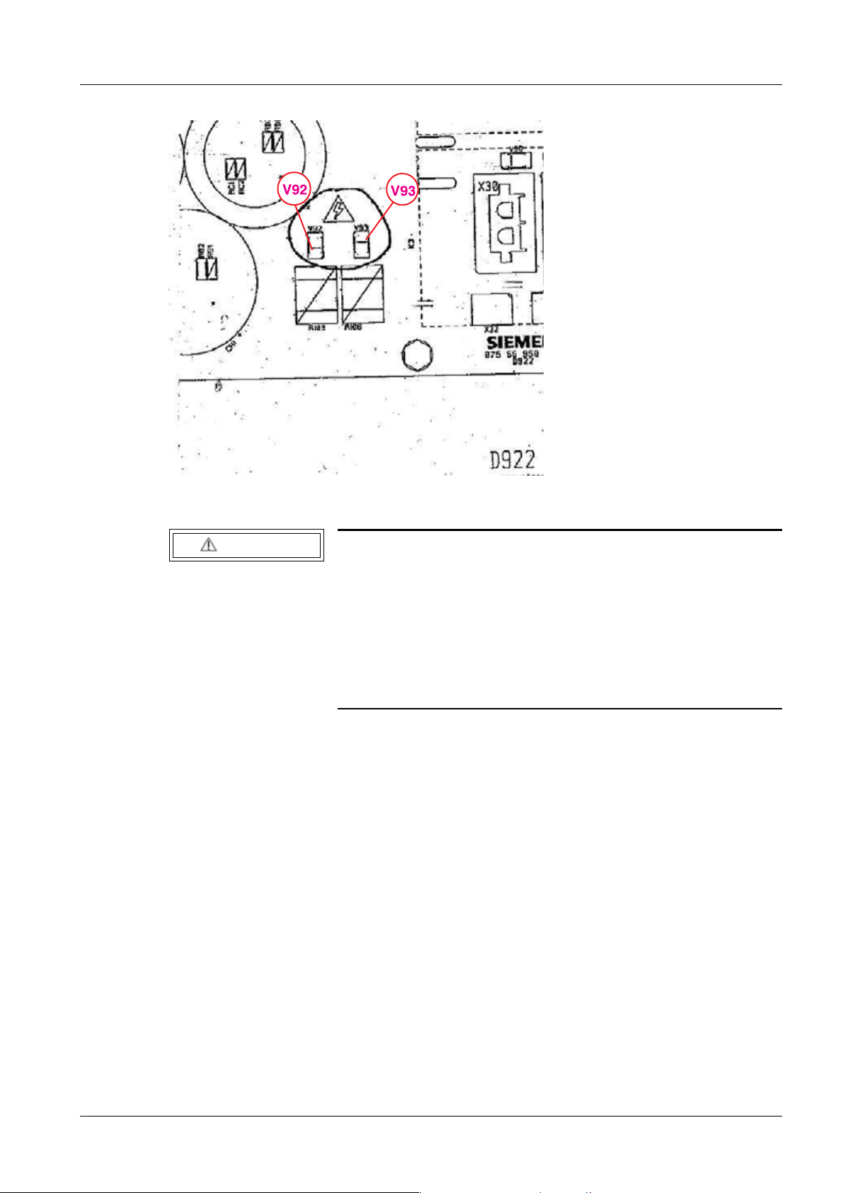
Fig. 1: D922_V92_V93
WARNING
POLYMOBIL III! To avoid electrical shock from components
under voltage, also be aware that:
After the system is switched off, around 300 V direct voltage
are present in the control console for the main inverter.
¹ Before beginning any service work, wait until the volt-
age drops to approx. 12V within approx. 1.5 minutes;
the LED‘s V92 and V93 on D922 are then off. V92: - 330
V, V93: + 330 V, see (Fig.1/p.9).
• Connect the POLYMOBIL Plus / III only to a line voltage supply (receptacle) that com-
plies with the requirements of VDE 0107 or corresponds to the local national standards.
• In general, switch off the system and disconnect the power cable from the mains prior to
any service work.
• Remove or insert boards with the generator switched OFF only; observe ESD guide-
lines when handling boards.
Siemens SPR8-125.840.10.04.02 POLYMOBIL III/Plus
05.09 CS SD SP/ CO
Page 9 of 104
Page 10
10 General
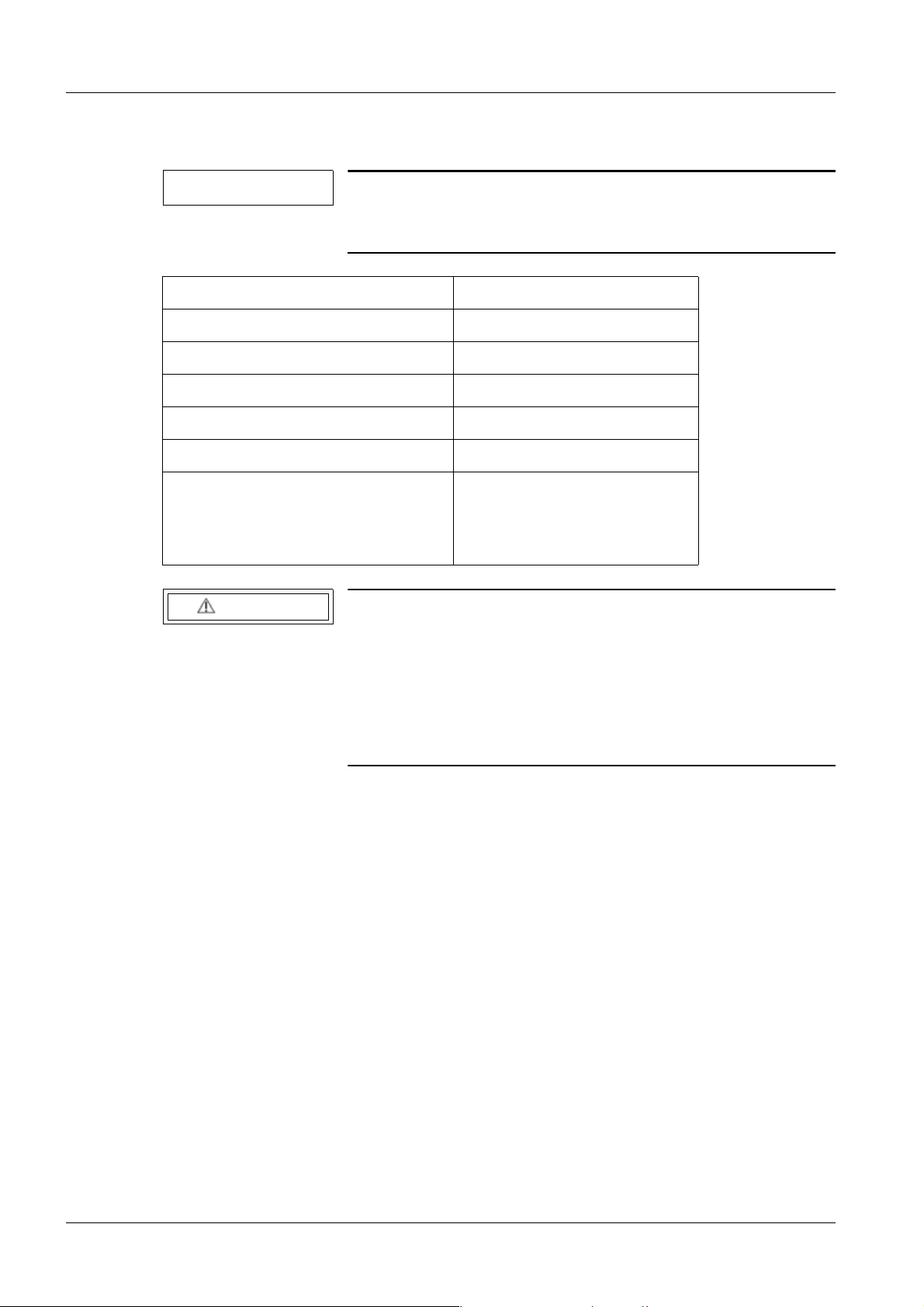
Tools, measurement and auxiliary devices 1.2
NOTE
All tools, measurement and auxiliary devices with the exception of those marked " * " are listed along with their specifications in the STC (Service Tools Catalog).
Standard service kit* n/a
Digital multimeter n/a
2-channel memory oscilloscope n/a
mAs meter n/a
Protective conductor meter n/a
Equivalent leakage current meter n/a
Current transformer (50 A : 50 mA)*
Part no. 31 51 289
In addition, a metal film resistor with
10 Ohms; 0.5 W; 1% is required*
Refer also to Speed Info 06/91
WARNING
Dangerous electrical voltage present during service work!
Risk of death or serious physical injury.
¹ The oscilloscope must be connected to ground before
measurements are performed. A TEK video isolator
and the trigger set must be used whenever there is a
risk of ground loops distorting the measurement
results (see ARTD-002.731.22...).
POLYMOBIL III/Plus SPR8-125.840.10.04.02 Siemens
05.09 CS SD SP/ CO
Page 10 of 104
Page 11

General 11
Cleaning 1.3
• The unit must always be switched off and disconnected from the mains before clean-
ing. Use only water to clean the unit or a lukewarm solution consisting of water and a
household cleaning agent.
• Do not use abrasive cleaning agents or organic solvents such as benzene, alcohol, or
spot remover.
• Do not spray water on the unit.
• For additional information, refer to the Operating Instructions.
Siemens SPR8-125.840.10.04.02 POLYMOBIL III/Plus
05.09 CS SD SP/ CO
Page 11 of 104
Page 12

12 Overview
2- 2Overview
NOTICE
To check the assemblies, remove the upper covers, the handles, and the lower front cover of the switchbox.
¹ Follow the Replacement Instructions,
SPR8-125.841.10...
POLYMOBIL III/Plus SPR8-125.840.10.04.02 Siemens
05.09 CS SD SP/ CO
Page 12 of 104
Page 13
Overview 13
POLYMOBIL III 2.1
D916 0
D916 CPU, control and measurement value acquisition
Overview D916:
Name Function / Information Value
V24 This blinks when the software
is working
P1 This adjusts the mAs counter Adjusted service program 14:
P2 Not used n/a
P3 Adjustment of the maximum
frequency of the heating converter
P4 Adjustment of the maximum
frequency of the main inverter
P5 Adjustment of heating current Test point "I" Resonance, pre-adjust-
SW2B Operating modes:
n/a
320 kHz
(test point F1 adjusted in the factory)
Service Program 9:
80 kHz ± 1 kHz
(Test point "FC1")
Service Program 7:
24.5 kHz ± 0.5 kHz
(test point "FC2")
ment:
test point "IH" fine tuning
Normal: Position 1
Normal / service
SW1 For factory use only Do not use
SW3 Button
Operating modes:
Activation/reset
Power connector D916.X15:
Siemens SPR8-125.840.10.04.02 POLYMOBIL III/Plus
05.09 CS SD SP/ CO
Page 13 of 104
Service: Position 2
SW2B in position 2: Press
= Service Mode
SW2B in position 1: Press
= Normal Mode
Page 14
14 Overview
D916.X15 Pin Color
1 black Ground (+ 5 V)
3 black Ground (+ 5 V)
4 red + 5 V ± 5 %
5 brown +15 V ± 10%
6 blue Ground (+/- 15 V)
7 yellow -15 V ± 10%
LED D916:
V24 ON Blinking during exposure
Potentiometers D916:
P1 OFFSET of mAs converter. Set at the factory - Do not change!
P3 Filament inverter frequency
P4 Main inverter frequency
P5 Adjustment/setting of filament heating circuit
Reset - switch
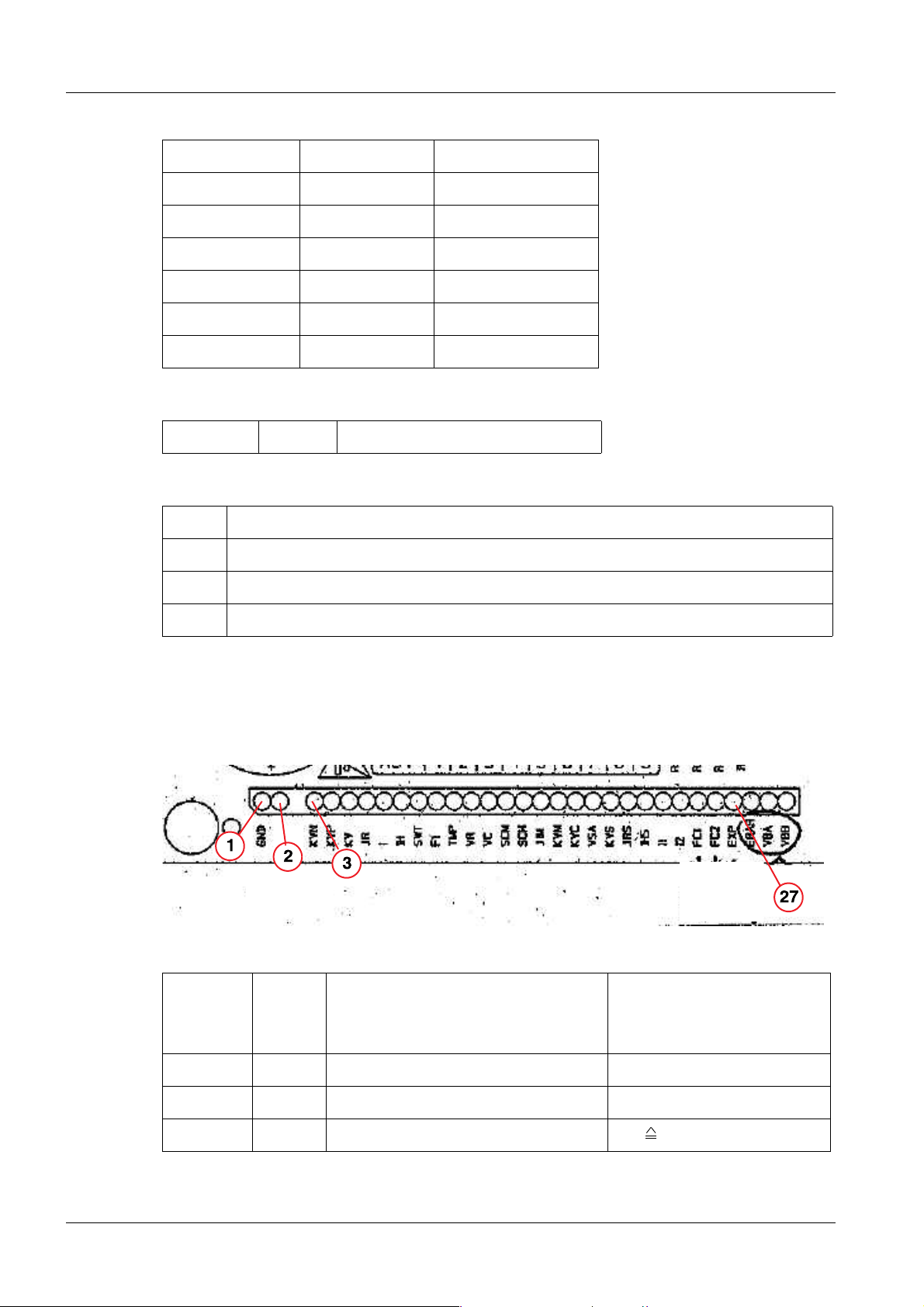
Test points D916 CPU
Fig. 2: D916_test points
Left to
right
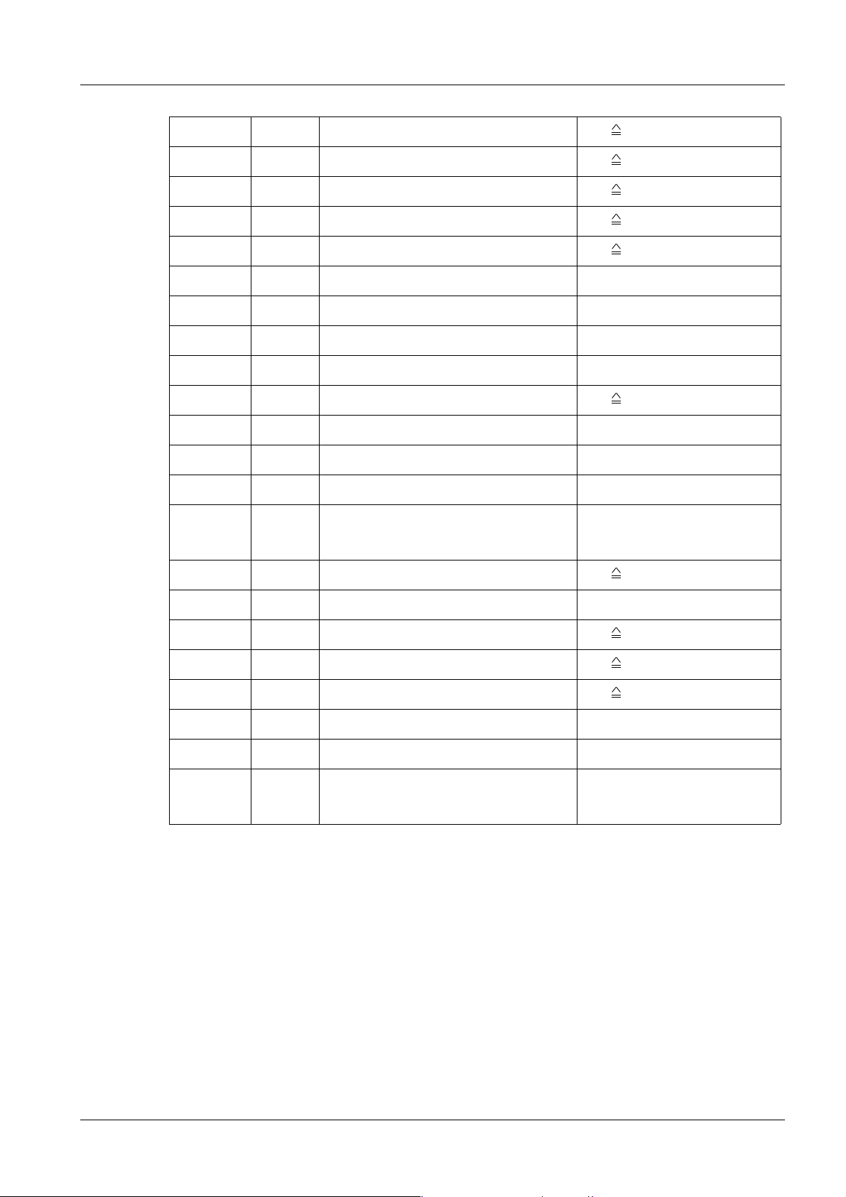
TP Function/information Measurement
Range
1 GND Mass measurement n/a
2 GND Mass measurement n/a
3 KVN Negative branch 1 V 10 k V
POLYMOBIL III/Plus SPR8-125.840.10.04.02 Siemens
05.09 CS SD SP/ CO
Page 14 of 104
Page 15
Overview 15
4 KVP Positive branch 1 V 10 k V
5 KV “Kv Ist” in tube 1 V 30 k V
6 JR Tube current 1 V 10 mA
7 I Heating resonant current 1 V 1 A (primary)
8 IH Heating current 1 V 1.2 A (secondary)
9 SWT Switching to regulate tube current High = kV > 70% “KV soll”
10 F1 mAs integration frequency max. 5V/ 320 kHz
11 TMP Single tank temperature
12 VR Reference voltage 5 V - dc ± 0.01
13 VC Capacitor bank voltage 1 V 100 V
14 SCM Main inverter short circuit Error 35 and 4
15 SCH Heating inverter short circuit Error 22, 36, 15 and 12
16 JIM Tube overcurrent (heating or rays) Error 23 or Error 34
17 KVM KV overvoltage (positive or negative
branch)
18 KVC Main inverter resonance current 1 V 50 A
19 VSA Not used n/a
20 KVS "KV soll" (kv selected) 1 V 30 kV
21 JRS "Soll tube current" (mA required) 1 V 10 mA
22 IHS "Soll heating current" (ih required) 1 V 1.2 As
25 FC1 Current inverter frequency
26 FC2 Main inverter frequency
27 EXP High = no exposure (kV regulator
disabled) Low = Exposure
Error 31
D922, filament inverter, ON/OFF switching circuit 0
LED:
Siemens SPR8-125.840.10.04.02 POLYMOBIL III/Plus
05.09 CS SD SP/ CO
Page 15 of 104
Page 16
16 Overview
V86 +15 V for inverter frequency OK and 24 V presence
V85 24 V presence
V15 Auxiliary voltage OK
V3 Collimator On
V93, V92 DC voltage BUS
Fuses:
F1 15 AT Phase line fuse
F2 15 AT Neutral line fuse
F3 1 AT +24 voltage fuse
Measurement points:
VP 0V
0V24 Ground 24V
P24V +24V
HIP5 +5V
GNDA Ground 5V
HIER Error drivers heating current
(ground for tester GNDA)
HID1 control TRANSISTOR High
(ground for tester GNDA)
HID2 control TRANSISTOR Low
(ground for tester GNDA)
FAUX Hz generation auxiliary supplies
HVD1 Control transistors High and Low of the
other branch (Main Inverter)
(ground for tester GNDC)
HVD2 Control transistors Low and High of the
other branch (Main Inverter)
(ground for tester GNDC)
HVRS Reset of the drivers of Main Inverter
HVER Error in the drivers of Main Inverter
POLYMOBIL III/Plus SPR8-125.840.10.04.02 Siemens
05.09 CS SD SP/ CO
Page 16 of 104
Page 17

Overview 17
U1 power supply unit 5 V ± 5% / 15 V ± 10% 0
Fuse: 2 A T
U2 power supply unit 12.5 V ± 10% 0
Fuse: 5 A T
D98 Display board 0
The display board shows the selected mAs and KV values. By pressing the membrane keyboard button, you can change the ON/OFF, KV, and mAs values.
D1/ Measurement circuit 0
The D1 measurement board of the high voltage main circuit represent KV and mA values
to the CPU.
C1/ Inverter capacitor 0
The C1 capacitor is the capacitive portion of the main inverter. The C1 single tank belongs
to the high voltage circuit.
Pre-load and discharge resistors 0
The pre-load and discharge resistors are responsible for the switch-on current and the discharge of the capacitor within 10 minutes after the system has been switched off, from
approximately 400VDC to a level below 10VDC.
Status of the LEDs (optimum condition) 0
a) POLYMOBIL III OFF, line voltage plug connected:
D922: LED V85 24V presence
b) POLYMOBIL III ON, standby
D922: LED V86 ON 15V and 24V presence
LED V85 ON 24V presence
LED V15 ON Auxiliary voltage OK
LED V93 ON DC bus voltage
Siemens SPR8-125.840.10.04.02 POLYMOBIL III/Plus
05.09 CS SD SP/ CO
Page 17 of 104
Page 18

18 Overview
LED V92 ON DC bus voltage
LED V3 OFF ON, if collimator button is pushed
POLYMOBIL III/Plus SPR8-125.840.10.04.02 Siemens
05.09 CS SD SP/ CO
Page 18 of 104
Page 19

Overview 19
POLYMOBIL Plus 2.2
D916 0
D916 CPU, control and measurement value acquisition
Overview D916:
Name Function / Information Value
V24 This blinks when the software
is working
P1 This adjusts the mAs counter Adjusted service program 14:
P2 Not used n/a
P3 Adjustment of the maximum
frequency of the heating converter
P4 Adjustment of the maximum
frequency of the main inverter
P5 Adjustment of heating current Test point "I" Resonance, pre-adjust-
SW2B Operating modes:
n/a
320 kHz
(test point F1 adjusted in the factory)
Service Program 9:
80 kHz ± 1 kHz
(Test point "FC1")
Service Program 7:
18 kHz ± 0.5 kHz
(test point "FC2")
ment:
test point "IH" fine tuning
Normal: Position 1
Normal / service
SW1 For factory use only Do not use
SW3 Button
Operating modes:
Activation/reset
Power connector D916.X15:
Siemens SPR8-125.840.10.04.02 POLYMOBIL III/Plus
05.09 CS SD SP/ CO
Page 19 of 104
Service: Position 2
SW2B in position 2: Press
= Service Mode
SW2B in position 1: Press
= Normal Mode
Page 20
20 Overview
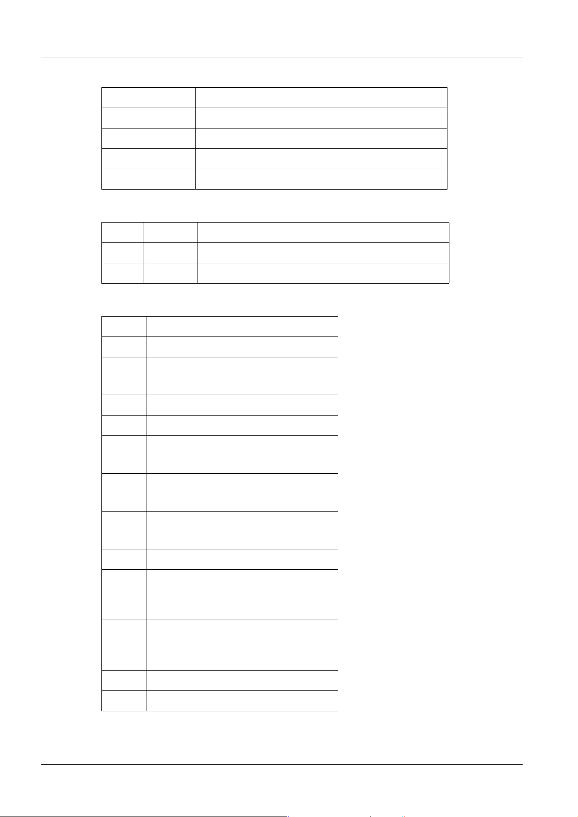
D916.X15 Pin Color
1 black Ground (+ 5 V)
3 black Ground (+ 5 V)
4 red + 5 V ± 5 %
5 brown +15 V ± 10%
6 blue Ground (+/- 15 V)
7 yellow -15 V ± 10%
LED D916:
V24 ON Blinking during exposure
Potentiometers D916:
P1 OFFSET of mAs converter. Set at the factory - Do not change!
P3 Filament inverter frequency
P4 Main inverter frequency
P5 Adjustment/setting of filament heating circuit
Reset - switch
Test points D916 CPU
Left to
right
Range
1 GND Mass measurement n/a
2 GND Mass measurement n/a
3 KVN Negative branch 1 V 10 k V
4 KVP Positive branch 1 V 10 k V
5 KV “Kv Ist” in tube 1 V 30 k V
TP Function/information Measurement
6 JR Tube current 1 V 100 mA
7 I Heating resonant current 1 V 1 A (primary)
8 IH Heating current 1 V 1.2 A (secondary)
9 SWT Switching to regulate tube current High = kV > 70% “KV soll”
10 F1 mAs integration frequency max. 5V/ 320 kHz
POLYMOBIL III/Plus SPR8-125.840.10.04.02 Siemens
05.09 CS SD SP/ CO
Page 20 of 104
Page 21
Overview 21
11 TMP Single tank temperature
12 VR Reference voltage 5 V - dc ± 0.01
13 VC Capacitor bank voltage 1 V 100 V
14 SCM Main inverter short circuit Error 35 and 4
15 SCH Heating inverter short circuit Error 22, 36, 15, and 12
16 JIM Tube overcurrent (heating or rays) Error 23 or Error 34
17 KVM KV overvoltage (positive or negative
branch)
18 KVC Main inverter resonance current 1 V 50 A
19 VSA Not used n/a
20 KVS "KV soll" (kv selected) 1 V 30 kV
21 JRS "Soll tube current" (mA required) 1 V 100 mA
Error 31
22 IHS "Soll heating current" (ih required) 1 V 1.2 As
23 I1 "Motor current" (stator 1 rewinding) 1 V 4 A
24 I2 "Motor current" (stator 2 rewinding) 1 V 4 A
25 FC1 Current inverter frequency
26 FC2 Main inverter frequency
27 EXP High = no exposure (kV regulator
disabled) Low = Exposure
28 ERAR Starter signal Error 28
Siemens SPR8-125.840.10.04.02 POLYMOBIL III/Plus
05.09 CS SD SP/ CO
Page 21 of 104
Page 22
22 Overview
D927 0
Fig. 3: D927_V40_V41
Name Function / Information Value
P1 Collimator voltage adjustment Adjusted to obtain > 180 lux in light
field
(Approx. 25 V in connector X7).
V12 Presence of + 24 V DC n/a
V5 Enables + 15 V DC n/a
V40 Capacitor bank
Voltage indication
V41 Capacitor bank
Voltage indication
V46 Internal power supplies
are working
V59 Collimator on n/a
n/a
n/a
n/a
Fuse value referring to
F3 1 AT (250 V ∼ / slow) n/a
POLYMOBIL III/Plus SPR8-125.840.10.04.02 Siemens
05.09 CS SD SP/ CO
Page 22 of 104
Page 23
Overview 23
F5 6 AF (500 V DC / fast) n/a
F6 20 AF (500 V DC / fast) n/a
F7 15 AF (250 V ∼ / slow) Line voltage
F8 15 AF (250 V ∼ / slow) Line voltage
U1 power supply unit 5 V ± 5% / 15 V ± 10% 0
Fuse: 2 A T
U2 power supply unit 12.5 V ± 10% 0
Fuse: 5 A T
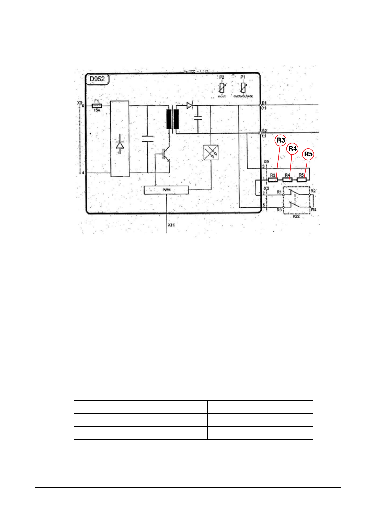
D952 capacitor charging circuit 0
LED:
Vin (V8) ON Line voltage OK
VDC (V1) ON Capacitor voltage present (the voltage can also be consider-
ably lower than 450 V)
V31 Charging cycle (OFF --> not charging) / (ON --> charging)
V30 Error indication (OFF --> OK) / (ON --> with errors)
V32 Enable charger (ON --> enable charging) / (OFF --> disable)
Fuse:
F1 15 AT
(250 V ∼ / delayed)
Test points:
ERR Error output charging error
VC Capacitor voltage 1 V : 100 V
Charging circuit
IC Capacitor charging current
FR1 Charging circuit frequency (dependent on the line voltage and VC)
GND Ground
CAR Signal to enable the charger
NCBC CAR enable and charging
OK Signal to indicate the full charge
Siemens SPR8-125.840.10.04.02 POLYMOBIL III/Plus
05.09 CS SD SP/ CO
Page 23 of 104
Page 24
24 Overview
D971 (capacitor bank) 0
LED:
Name Function / Information Value
V1 - 10 C1 - C10 (10mF) charged > 40V Yellow LEDs ON
Fuse value referring to
F1-F10 20 A (500 V DC / fast) C1 - C10 individual capacitor
F12 20 A (500 V DC / fast) Capacitor bank input
F11 100 A (500 V DC / high speed) Capacitor bank output
D98 Display board 0
The display board shows the selected mAs and KV values. By pressing the membrane keyboard button, you can change the ON/OFF, KV, and mAs values.
C1 main inverter capacitor 0
6.8 µV ±10 %
C2 0
C2 is the capacitor used to accelerate the rotor (phase shift); it is connected to the XCAP
connector.
K22 switch-on relay 0
Connects and disconnects the discharge resistors.
POLYMOBIL III/Plus SPR8-125.840.10.04.02 Siemens
05.09 CS SD SP/ CO
Page 24 of 104
Page 25
Overview 25
Discharge resistors 0
Fig. 4: R3_R4_R5
R3, R4 and R5 --> 510 Ohm ± 5%.
They have to be screwed down tight to prevent their being damaged.
Status of the LEDs (optimum condition) 0
a) POLYMOBIL Plus OFF, line voltage plug connected:
D952: LED 450 VDC (V1) glows for 10 minutes following
shutdown
D971: all LEDs glows for 10 minutes following
shutdown
b) POLYMOBIL Plus ON, standby
D952: LED Vin (V8) ON
LED 450 VDC (V1) ON
D971: all LEDs ON
Siemens SPR8-125.840.10.04.02 POLYMOBIL III/Plus
05.09 CS SD SP/ CO
Page 25 of 104
Page 26

26 Error Messages
POLYMOBIL III 0
3- 3Error Messages
Error 1 - Loss of the + 15 V dc 0
Error 1 + 15 V missing
System status:
Standby
Explanation:
Action:
• Check X15 (D916):
- Pin 1, 3: 0V
- Pin 4 : 5V
- Pin 5: +15V
- Pin 6: 0V
- Pin 7: -15V
• Check the U1 power supply and the cable connection at the
U1.
Error 3 - Oil pressure rise or overheating of the tube 0
Error 3 Oil pressure rise or overheating of the tube
System status:
Standby
Explanation:
Action:
• Check the oil switch.
(Normal tube condition = switch closed)
¹ Warning: let the tube cool off before testing!
• Check the connections and the cable between the switch
and the D916 X8-9 and X8-8.
POLYMOBIL III/Plus SPR8-125.840.10.04.02 Siemens
05.09 CS SD SP/ CO
Page 26 of 104
Page 27

Error Messages 27
Error 4 - Static short circuit of the main inverter 0
Error 4 Static short circuit of the main inverter
System status:
Standby
Explanation:
Action:
• Check the power supplies U1 / U2 and the connections to
the main inverter.
¹ Some other possible causes are: capacitor C1 or
D922 may be defective.
• Disconnect capacitor C1.
- Warning: Turn off the equipment. Wait 10 minutes for it
to discharge. Turn it back on.
- If the error disappears, then it might be the tube, C1, the
cables and/or the connections to the tube.
Error 6 - IH heating measured < IH of preheating 0
Error 6 IH heating measured < IH of preheating
System status:
Standby
Explanation:
Action:
• Compare IH and IHS in D916 to make sure they are not the
same.
• Check the frequency of the heating inverter in the D916
TP - FC1.
• Check the form of the resonance current at the TP-I D916
(use Service Program 9).
¹ Possible causes are a bad cable connection from
D916 to D1(X8) (high resistance) to the single tank, a
defective heating inverter on board D922, a defective
heating transformer (single tank), the filament in the
single tank is defective, the D916 and/or the D922 are
defective, or the tube is defective.
Siemens SPR8-125.840.10.04.02 POLYMOBIL III/Plus
05.09 CS SD SP/ CO
Page 27 of 104
Page 28

28 Error Messages
Error 7 - IH heating measured > IH allowed by software 0
Error 7 IH heating measured > IH allowed by software.
System status:
Standby
Explanation:
Action:
• Before inhibition, IHM exceeds 3.75V; i.e. 4.25A max.
allowed.
• Check the form of the resonance current in the TP-I D916.
¹ Some possible causes are bad cable connections
from D916 to D1 (X8), or D916 and/or D922 are defective, or the tube is defective (filament).
Error 8 - kV measured < > 0 in idle 0
Error 8 kV measured < > 0 in idle
System status:
Standby
Explanation:
Action:
• Check the cable connections D916 to D1 (X8).
¹ Some other possible causes may be: the CPU D916
and/or the D922 and/or the tube are defective.
Error 9 - mA measured < > 0 in idle 0
Error 9 mA measured < > 0 in idle
System status:
Standby
Explanation:
Action:
• Check the cable connections, especially the ones between
the tube and the CPU D916 (X8).
¹ Some other possible causes may be: the CPU D916
or the tube is defective.
POLYMOBIL III/Plus SPR8-125.840.10.04.02 Siemens
05.09 CS SD SP/ CO
Page 28 of 104
Page 29

Error Messages 29
Error 11 - Voltage too high in the capacitor bank 0
Error 11 Voltage too high in the capacitor bank.
System status:
Standby
Explanation:
D916 (CPU) detects overvoltage (> 440 V) in the capacitor
bank. After the system is switched on, the capacitor bank voltage is about 440 V (VC). This voltage is reduced to 1% of its
former level and the reduced voltage can be measured on
board D916, TP VC.
Action:
• Check the VC test point of the D916 and check the voltage
directly in the capacitor bank VC (possible point: HVVC in
D922).
Error 12 - Noise in the static short circuit signal in the heating inverter 0
Error 12 Noise in the static short circuit signal in heating
System status:
Standby
Explanation:
Action:
• Check the SCH test point on the D916 (a high level means
a short circuit).
• Check the cable connection between the D916 CPU and the
power board D922.
• Switch off the system and disconnect X5 on the power
board D922. Switch on the system. .
¹ If Error 6 appears, the CPU D916 should be OK.
Check D922, cable connection to the single tank.
¹ If Err 12 is still displayed, replace D916 CPU.
• If the Err 12 disappears, the D916 CPU is OK.
• Then look over the possible problems on the power board
D922, the tube and the wiring.
Siemens SPR8-125.840.10.04.02 POLYMOBIL III/Plus
05.09 CS SD SP/ CO
Page 29 of 104
Page 30

30 Error Messages
Error 13 - Voltage in the capacitor bank is low during charge process 0
Error 13 Voltage in the capacitor bank is low during charge process
System status:
Standby
Explanation:
The voltage in the capacitor bank is lower than the voltage
expected from the CPU. The capacitor bank voltage after the
system is switched on is about 400V (VC) and divided on board
100:1 to be monitored from the CPU (Vc).
Action:
• Check the cable connection between the CPU and the D922
(X20).
• Check the VC test point of the D916, and check the voltage
directly in the capacitor bank VC (possible point: HVVC on
D922).
Error 15 - Static short circuit, heating inverter 0
Error 15 Static short circuit, heating inverter
System status:
Standby
Explanation:
Action:
• Check the SCH test point of the D916 (a high level means a
short circuit of the heating inverter).
• Switch off the system and disconnect X5 on the power
board D922. Switch on the system. .
¹ If Error 6 appears, the CPU D916 should be OK.
Check D922, cable connection to the single tank.
¹ If Err 15 is still displayed, replace D916 CPU.
¹ If Err 15 disappears, then the D922 is OK.
• Use Service Program 9 and check the maximum frequency
of the heating inverter (refer to document "Replacement of
parts" SPR8-125.841.10..).
POLYMOBIL III/Plus SPR8-125.840.10.04.02 Siemens
05.09 CS SD SP/ CO
Page 30 of 104
Page 31

Error Messages 31
Error 22 - short circuit, heating inverter 0
Error 22 Short circuit, heating inverter
System status:
Preparation
Explanation:
Action:
• Check the SCH test point of the D916 (a high level means a
short circuit of the heating inverter).
• Check cable connection to the tube.
• Switch off the system and disconnect X5 on the power
board D922. Switch on the system.
¹ If Error 6 appears, the CPU D916 should be OK.
Check D922, the cable connection to the single tank,
and the single tank.
¹ If Err 22 is still displayed, replace D916 CPU.
¹ If Err. 22 disappears, then the D922 is OK.
• Short circuit outside the tube, look over the connections and
wiring that go to the tube.
• Use Service Program 9
and check the maximum frequency of the heating inverter.
Error 23 - Tube current limitation 0
Error 23 Tube current limitation
System status:
Preparation
Explanation:
Action:
• Check the JIM test point of the D916 (a high level means a
tube current error).
• Use Service Program 9
and check the filament current of the tube (refer to document "Replacement of parts" SPR8-125.841.10...).
¹ It is possible that the filament inside the tube is defec-
tive.
¹ It is possible that the filament current in preparation is
bad. Adjust with the potentiometer P5 on the D916.
Siemens SPR8-125.840.10.04.02 POLYMOBIL III/Plus
05.09 CS SD SP/ CO
Page 31 of 104
Page 32

32 Error Messages
Error 25 - Preparation timeout 0
Error 25 Preparation timeout
System status:
Preparation
Explanation:
This error occurs when preparation time (hand switch, first step)
exceeds 15 seconds without an exposure being taken.
Action:
• If this error occurs without the hand switch being activated
for more than 15 seconds, then check the connection
between the hand switch and the CPU.
It may be bad or the CPU may be defective.
Error 31 - kV limit 0
Error 31 kV limit
System status:
Exposure
Explanation:
Action:
• Check the KVM test point of the D916 (a high level means
an error).
• Check the signal cable connection between the tube and the
D916.
• Check the maximum frequency of the main inverter (Service
Program 7, refer also to document "Replacement of parts"
SPR8-125.841.10...).
• Check the filament current (Service Program 9), refer also
to document "Replacement of parts" SPR8-125.841.10...).
¹ Possible defects: the D916 or the D1 may be defective.
POLYMOBIL III/Plus SPR8-125.840.10.04.02 Siemens
05.09 CS SD SP/ CO
Page 32 of 104
Page 33

Error Messages 33
Error 34 - Tube current limit 0
Error 34 Tube current limit
System status:
Exposure
Explanation:
Action:
• Check the JIM test point of the D916 (A high level means a
tube current error).
• Use Service Program 9 and check the filament current and
the maximum frequency of the heating inverter (refer to document "Replacement of parts" SPR8-125.841.10...).
¹ It is possible that the filament inside the tube is defec-
tive.
¹ It is possible that the filament current in preparation is
bad. Adjust with the potentiometer P5 on the D916.
• Analyze to see if other error messages appear, especially
with high or low KV’s.
¹ A short-circuit problem may exist in the tube.
Error 35 - Short circuit in the main inverter 0
Error 35 Short circuit in the main inverter
System status:
Exposure
Explanation:
Action:
• Check the SCM test point in D916 (a high level means a
short circuit error); it is possible the tube is defective.
• Check the cable connections between the D916 and the
D922 (X20).
• Check the cable connections between the D922 and the
tube XoutA XoutB.
• Check C1.
Siemens SPR8-125.840.10.04.02 POLYMOBIL III/Plus
05.09 CS SD SP/ CO
Page 33 of 104
Page 34

34 Error Messages
Error 36 - Short circuit in the heating inverter 0
Error 36 Short circuit in the heating inverter
System status:
Exposure
Explanation:
Action:
• Check SCH signal in the D916 (A high level means a short
circuit).
• Check the maximum filament frequency and the signal in
test point I (Service Program 9), (refer to the document
"Replacement of parts" SPR8-125.841.10...)
• Check the cable connections between the D922 (X5) and
the tube.
¹ Possible defect: D922
Error 37 - Regulation failure in the kV loop 0
Error 37 Regulation failure in the kV loop
System status:
Exposure
• kV_actual (KV) is in a different range than kV_nominal
(KVS).
• Check the connections between the D916 (X8) and the
tube.
¹ The D916 may be faulty.
¹ Check heating current adjustment, using P5 (very
important if D916 will be replaced!) - see “Replacement of Parts”, SPR8-125.841.10...
Error 38 – Regulation failure in the mA loop 0
Error 38 Regulation failure in the mA loop
System status:
Exposure
• i_actual (JR) is in a different range than kV_nominal (JRS).
• Check the connections between the D916 (X8) and the
tube.
¹ The D916 may be faulty.
POLYMOBIL III/Plus SPR8-125.840.10.04.02 Siemens
05.09 CS SD SP/ CO
Page 34 of 104
Page 35

Error Messages 35
Error 39 - Exposure timeout 0
Error 39 Exposure timeout
System status:
Exposure
• Check the frequency of the heating inverter at the D916 test
point FC1 (Service Program 9).
¹ The system interrupts the exposure. This may occur
when the mAs integrator fails in the D916.
Error 41 - The exposure has not finished 0
Error 41 The exposure has not finished.
System status:
Exposure
• The exposure switch is released during exposure.
¹ If the interruption was caused by another problem, it
may be a kV and/or mA regulation failure. Also see
errors Err 37 and Err 38.
Error 42 - Heating current limit 0
Error 42 Heating current limit
System status:
Exposure
• Check the JIM test point on the D916.
• Check heating current (Service program 9). It is possible
that the potentiometer P5 is not properly adjusted (the preparation current is too low).
Error 92 - RAM failure 0
Error 92 RAM/D916 failure.
System status:
Init
• Replace D916
Error 93 - Failure in the initial verification of the + 15 V DC 0
Error 93 Failure in the initial verification of the + 15 V DC
System status:
Init
• Check the voltages of U1 and D916 X15.
- + 15 V D916 X15 Pin 5 - 6
- - 15 V D916 X15 Pin 6 - 7
- + 5 V D916 X15 Pin 4 - 3
Siemens SPR8-125.840.10.04.02 POLYMOBIL III/Plus
05.09 CS SD SP/ CO
Page 35 of 104
Page 36

36 Error Messages
Error 94 - Difference between doubler signal and voltage level 0
Error 94 Difference between doubler signal and voltage level
System status:
Init
• Check cable X10
• Check cable X in D922 that comes from filter
• Check mains resistance
Error 95 - Precharge Error 0
Error 95 Precharge Error
System status:
Init
Explanation: Voltage below 80V after 9 seconds
• Check mains resistance.
• Check cable X in D922 that comes from filter.
Error 96 - Failure of Channel D (KV_NOM) in A/D converter 0
Error 96 Failure of Channel D (KV_NOM) in A/D converter
System status:
• Failure of CPU Channel D (KV_NOM) in A/D converter.
Init
¹ The CPU D916 is faulty.
Error 97 - Failure of Channel B (JR_NOM) in A/D converter 0
Error 97 Failure of Channel B (JR_NOM) in A/D converter
System status:
Init
• Failure of CPU Channel B (JR_NOM) in A/D converter.
¹ The CPU D916 is faulty.
Error 98 - Failure of Channel C (Ih_NOM) in A/D converter 0
Error 98 Failure of Channel C (Ih_NOM) in A/D converter
System status:
Init
• Failure of CPU Channel C (Ih_NOM) in A/D converter.
¹ The CPU D916 is faulty.
POLYMOBIL III/Plus SPR8-125.840.10.04.02 Siemens
05.09 CS SD SP/ CO
Page 36 of 104
Page 37

Error Messages 37
POLYMOBIL Plus 3.1
"Pause" error 0
Pause Message: "Pause"
System status:
Standby
Explanation: This message appears when the temperature of
the capacitor charging circuit board has exceeded a defined
value (caused by a number of exposures being taken within a
short time).
Action:
• Wait until the temperature has dropped.
• Error: If this message ("Pause") does not go away or if it
appears immediately after the unit is switched on, the D952
board may need to be replaced.
Error 1 - Loss of the + 15 V dc 0
Error 1 + 15 V missing
System status:
Standby
• Check X15 (D916):
- Pin 1, 3: 0V
- Pin 4: 5V
- Pin 6: 0V
- Pin 7: -15V
• Check the U1 power supply and the cable connection at the
U1.
Error 3 - Oil pressure rise or overheating of the tube 0
Error 3 Oil pressure rise or overheating of the tube
System status:
Standby
• Check the oil switch.
(Normal tube condition = switch closed)
¹ Warning: let the tube cool off before testing!
• Check the connections and the cable between the switch
and the D916 X8-9 and X8-8.
Siemens SPR8-125.840.10.04.02 POLYMOBIL III/Plus
05.09 CS SD SP/ CO
Page 37 of 104
Page 38

38 Error Messages
Error 4 - Static short circuit of the main inverter 0
Error 4 Static short circuit of the main inverter
System status:
Stand-by
• Check the power supplies U1 / U2 and the connections to
the main inverter.
¹ Some other possible causes are: capacitor C1 or
D927 may be defective.
• Disconnect capacitor C1.
- Warning: Turn off the equipment. Wait 10 minutes for it
to discharge. Turn it back on.
- If the error appears again, it may be that the D961 is
faulty.
- If the error disappears, then it might be the tube, the C1,
the cables, and/or the connections to the tube.
Error 6 - IH heating measured < IH of preheating 0
Error 6 IH heating measured < IH of preheating
System status:
Standby
• Compare: IH and IHS are not the same.
• Check the frequency of the heating inverter in the D916
TP - FC1.
• Check the form of the resonance current at the TP-I D916
(use service program 9).
¹ Some possible causes are a bad connection (high
resistance), faulty heating transformer, bad filament,
faulty D916 and/or D927 and/or the tube.
Error 7 - IH heating measured > IH allowed by software 0
Error 7 IH heating measured > IH allowed by software
System status:
Standby
• Before inhibition, IHM exceeds 4.26V, i.e. 5.12A
• Check the form of the resonance current in the TP-I D916.
¹ Some possible causes are bad cable (resistance),
faulty D916 and/or D927 and/or the tube
POLYMOBIL III/Plus SPR8-125.840.10.04.02 Siemens
05.09 CS SD SP/ CO
Page 38 of 104
Page 39

Error Messages 39
Error 8 - kV measured < > 0 in idle 0
Error 8 kV measured < > 0 in idle
System status:
Standby
• Check the cables, especially the ones between the tube and
the CPU (connector X8).
¹ Some other possible causes may be: the CPU D916
and/or the D927 and/or the tube are defective.
Error 9 - mA measured < > 0 in idle 0
Error 9 mA measured < > 0 in idle
System status:
Standby
• Check the cables, especially the ones between the tube and
the CPU (connector X8).
¹ Some other possible causes may be: the CPU D916
is faulty or the tube is faulty.
Error 11 - Voltage too high in the capacitor bank 0
Error 11 Voltage too high in the capacitor bank or capacitor loader
D952 is faulty.
System status:
Standby
Explanation:
D916 (CPU) detects overvoltage (> 440 V) in the capacitor
bank. After the system is switched on, the capacitor bank voltage is about 440 V (VC). This voltage is reduced to 1% of its
former level and the reduced voltage can be measured on
board D916, TP VC.
Action:
• Check the VC test point of the D916 and check the voltage
directly in the capacitor bank VC (possible points: between
the earth and fuse F5 located on D927).
Siemens SPR8-125.840.10.04.02 POLYMOBIL III/Plus
05.09 CS SD SP/ CO
Page 39 of 104
Page 40

40 Error Messages
Error 12 - Noise in the static short circuit signal in the heating inverter 0
Error 12 Noise in the static short circuit signal in heating
System status:
Standby
• Check the SCH test point on the D916 (a high level means
a short circuit).
• Check the cable connection between the D916 CPU and the
power board D927.
• Switch off the system and disconnect X5 on the power
board D927. Switch on the system.
¹ If the Err 12 disappears, the D916 CPU is OK.
Then look over the possible problems on the power
board D927, the tube and wiring.
Error 13 - Voltage in the capacitor bank is low during charge process 0
Error 13 Voltage in the capacitor bank is low during charge
System status:
Standby
Explanation:
The voltage in the capacitor bank is lower than the voltage
expected from the CPU. The capacitor bank voltage after the
system is switched on is about 440V (VC) and divided on board
100:1 to be monitored from the CPU (Vc).
Action:
• Check the connection between the CPU and the D952
(X20) and the connection between the D927 and the D952
(X3).
• Check the Vc test point of the D916 and the voltage directly
in the capacitor bank (possible points: between the earth
and fuse F5 located on D927).
¹ If VC and Vc are close to 440 V and 4.4 V, then D916
may be faulty.
¹ If VC is close to 440 V but Vc is not at 4.4 V, then either
the D952 or the D916 may be bad.
¹ If they are not close, then the D952 may be faulty.
POLYMOBIL III/Plus SPR8-125.840.10.04.02 Siemens
05.09 CS SD SP/ CO
Page 40 of 104
Page 41

Error Messages 41
Error 15 - Static short circuit, heating inverter 0
Error 15 Static short circuit, heating inverter
System status:
Standby
• Check the SCH test point of the D916 (a high level means a
short circuit of the heating inverter).
• Switch off the system and disconnect X5 on the power
board D927. Switch on the system.
¹ If Error 6 appears, the CPU D916 should be OK.
Check D927, cable connection to the single tank.
¹ If Err 15 is still displayed, replace D916 CPU.
¹ If Err15 disappears, then the D927 is OK.
• Use Service Program 9 and check the maximum frequency
of the heating inverter (refer to document "Replacement of
parts" SPR8-125.841.10...).
Error 22 - Short circuit, heating inverter 0
Error 22 Short circuit, heating inverter
System status:
Preparation
• Check the SCH test point of the D916 (a high level means a
short circuit).
• Check cable connection to the tube.
• Switch off the system and disconnect X5 on the power
board D922. Switch on the system.
¹ If Error 6 appears, the CPU D916 should be OK.
Check D927, the cable connection to the single tank,
and the single tank.
¹ If Err 22 is still displayed, replace D916 CPU.
¹ If Err. 22 disappears, then the D927 is OK.
• Short circuit outside the tube, look over connections and
wiring that go to the tube.
• Use Service Program 9
and check the maximum frequency of the heating inverter.
Siemens SPR8-125.840.10.04.02 POLYMOBIL III/Plus
05.09 CS SD SP/ CO
Page 41 of 104
Page 42

42 Error Messages
Error 23 - Tube current limitation 0
Error 23 Tube current limitation
System status:
Preparation
• Check the JIM test point of the D916 (A high level causes
the error).
• Use Service Program 9
and check the filament current of the tube (refer to document "Replacement of parts" SPR8-125.841.10...).
¹ It is possible that the filament inside the tube is bad.
¹ It is possible that the filament current in preparation is
bad (very high or very low). Adjust the potentiometer
P5 of the D916.
Error 24 - The anode does not get up to its startup speed 0
Error 24 The anode does not reach its startup speed
System status:
Preparation
• Check the I1 and I2 test points of D916.
• Check the connection to C2, the phase shift capacitor, the
XCap, and the X6 connector.
• Check the connection between the power board D927 X11
and CPU D916 X11.
• Check F5 6AT on the power board D927.
• Check F6 20AT on the power board D927.
Error 25 - Preparation timeout 0
Error 25 Preparation timeout
System status:
Preparation
• This error occurs when preparation time (hand switch, first
step) exceeds 15 seconds without an exposure being taken.
¹ If this error occurs without the hand switch being acti-
vated for more than 15 seconds, then check the connection between the hand switch and the CPU.
It may be bad or the CPU may be defective.
POLYMOBIL III/Plus SPR8-125.840.10.04.02 Siemens
05.09 CS SD SP/ CO
Page 42 of 104
Page 43

Error Messages 43
Error 28 - Starter short circuit 0
Error 28 Starter short circuit
System status:
Preparation
• Check the phase displacement capacitor (C2).
• Check the winding resistances of the stator (X6 - 3 - X6 - 1
should be close to 83 Ohms, X6 - 3 and C2 should be close
to 174 Ohms).
¹ Possible defects: the D927, C2 and check the cable
connection to the starter within the tube.
Error 31 - kV limit 0
Error 31 kV limit
System status:
Exposure
• Check the KVM test point of the D916 (a high level means
an error).
• Check test point KVC of the D916.
• Check the signal cable connection between the tube and the
D916.
• Check the maximum frequency of the main inverter (Service
Program 7), refer also to document "Replacement of parts"
SPR8-125.841.10...).
• Check the filament current (Service Program 9), refer also
to document "Replacement of parts" SPR8-125.841.10...).
¹ Possible defects: the D916 or the D900 may be defec-
tive.
Siemens SPR8-125.840.10.04.02 POLYMOBIL III/Plus
05.09 CS SD SP/ CO
Page 43 of 104
Page 44

44 Error Messages
Error 34 - Tube current limit 0
Error 34 Tube current limit
System status:
Exposure
• Check the JIM test point on the D916.
¹ It is possible that the potentiometer P5 is not properly
adjusted, thus causing the heating current in preparation to be very high.
• If an error exists in the entire range of kV during the expo-
sure, especially at low kVs, a problem must exist inside the
tube.
• Use Service Program 9 and check the filament current and
the maximum frequency of the heating inverter (refer to document "Replacement of parts" SPR8-125.841.10...).
¹ It is possible that the filament inside the tube is defec-
tive.
¹ It is possible that the filament current in preparation is
bad. Adjust with the potentiometer P5 on the D916.
• Analyze to see if other error messages appear, especially
high voltage ones.
¹ A short-circuit problem may exist in the tube.
Error 35 - Short circuit in the main inverter 0
Error 35 Short circuit in the main inverter
System status:
Exposure
• Check the SCM test point in D916.
¹ If a persistent error appears in the entire kV range dur-
ing the exposure, especially at low kVs, the tube may
be faulty.
• Check the connections between the D916 and the D961
(X20).
• Check the connections between the D961 and the tube
(U - V)/X4.
• Check C1.
POLYMOBIL III/Plus SPR8-125.840.10.04.02 Siemens
05.09 CS SD SP/ CO
Page 44 of 104
Page 45

Error Messages 45
Error 36 - Short circuit in the heating inverter 0
Error 36 Short circuit in the heating inverter
System status:
Exposure
• Check SCH signal in the D916 (A high level means a short
circuit).
• Check the maximum filament frequency and the signal in
test point I (Service Program 9), (refer to the document
"Replacement of parts" SPR8-125.841.10...)
• Check the connections between the D927 (X5) and the
tube.
¹ The D927 may be faulty.
Error 37 - Regulation failure in the kV loop 0
Error 37 Regulation failure in the kV loop
System status:
Exposure
• kV_actual (KV) is in a different range than kV_nominal
(KVS).
• Check the connections between the D916 (X8) and the
tube.
¹ The D916 may be faulty.
¹ Check heating current adjustment, using P5 (very
important if D916 will be replaced!) - see “Replacement of Parts”, SPR8-125.841.10...
Error 38 – Regulation failure in the mA loop 0
Error 38 Regulation failure in the mA loop
System status:
Exposure
• i_actual (JR) is in a different range than kV_nominal (JRS).
• Check the connections between the D916 (X8) and the
tube.
¹ The D916 may be faulty.
Error 39 - Exposure timeout 0
Error 39 Exposure timeout
System status:
Exposure
• Check the frequency of the heating inverter at the D916 test
point FC1 (Service Program 9).
¹ The system interrupts the exposure. This may occur
when the mAs integrator fails in the D916.
Siemens SPR8-125.840.10.04.02 POLYMOBIL III/Plus
05.09 CS SD SP/ CO
Page 45 of 104
Page 46

46 Error Messages
Error 41 - The exposure has not finished 0
Error 41 The exposure has not finished.
System status:
Exposure
• The exposure switch is released during exposure.
¹ If the interruption was caused by another problem, it
may be a kV and/or mA regulation failure. Also see
errors Err 37 and Err 38.
Error 42 - Heating current limit 0
Error 42 Heating current limit
System status:
Exposure
• Check the JIM test point on the D916.
• Check heating current (Service program 9). It is possible
that the potentiometer P5 is not properly adjusted (the preparation current is too low).
Error 92 - RAM failure 0
Error 92 RAM failure.
System status:
Init
• Replace D916
Error 93 - Failure in the initial verification of the + 15 V DC 0
Error 93 Failure in the initial verification of the + 15 V DC
System status:
Init
• Check the voltages of U1 and D916 X15.
- + 15 V D916 X15 Pin 5 - 6
- - 15 V D916 X15 Pin 6 - 7
- + 5 V D916 X15 Pin 4 - 3
Error 96 - Failure of Channel D (KV_NOM) in A/D converter 0
Error 96 Failure of Channel D (KV_NOM) in A/D converter
System status:
Init
• Failure of CPU Channel D (KV_NOM) in A/D converter.
¹ The CPU D916 is faulty.
POLYMOBIL III/Plus SPR8-125.840.10.04.02 Siemens
05.09 CS SD SP/ CO
Page 46 of 104
Page 47

Error Messages 47
Error 97 - Failure of Channel B (JR_NOM) in A/D converter 0
Error 97 Failure of Channel B (JR_NOM) in A/D converter
System status:
Init
• Failure of CPU Channel B (JR_NOM) in A/D converter.
¹ The CPU D916 is faulty.
Error 98 - Failure of Channel C (Ih_NOM) in A/D converter 0
Error 98 Failure of Channel C (Ih_NOM) in A/D converter
System status:
Init
• Failure of CPU Channel C (Ih_NOM) in A/D converter.
¹ The CPU D916 is faulty.
Siemens SPR8-125.840.10.04.02 POLYMOBIL III/Plus
05.09 CS SD SP/ CO
Page 47 of 104
Page 48

48 Service programs
General 0
4- 4Service programs
Activation of the service programs 0
• Turn off the unit.
• Take off the cover.
• Move the SW2B service switch to position 2 on the D916.
• Turn on the unit.
• "Pr 1" will appear on the display.
• For the selection of the required program, use mAs+ / mAs-
• To enter, press the collimator light button. To exit, press it again.
While we are in service programming, the X-rays are disabled.
To quit the service mode, move SW2B to position 1 and press the Reset button SW3, or
turn the POLYMOBIL OFF and then ON again.
POLYMOBIL III/Plus SPR8-125.840.10.04.02 Siemens
05.09 CS SD SP/ CO
Page 48 of 104
Page 49

Service programs 49
POLYMOBIL III 4.1
Service programs 0
Program 2 - exposure counter
Program 2
• Press the collimator light button to enter.
• Read the exposure counter on the display.
• Press the collimator light button to exit.
NOTE:
A reset is not possible. In the event that the tube is changed, make a note
of the start triggers.
Program 3 - error buffer
Program 3
• Press the collimator light button to enter.
• Show the last 20 errors on the display.
• On the left, the position it occupies is shown.
• On the right, the error code is indicated.
• The most recent errors are shown at the top of the list.
• To go backwards, use the "mAs-" key.
• Press the collimator light button to exit.
Program 4 - deletion of error buffer
Program 4
• Press the collimator light button to enter.
• To delete, press the "kV+" button for approximately 4 seconds.
• Press the collimator light button to exit.
Siemens SPR8-125.840.10.04.02 POLYMOBIL III/Plus
05.09 CS SD SP/ CO
Page 49 of 104
Page 50

50 Service programs
Program 5 - Change of initial values (kV and mAs) or last value
Program 5
• Press the collimator light button to enter.
• Press kV+, kV- and/or mAs+/mAs- to select the values.
• To save the values, press the collimator light button.
Program 6 - maximum values of kV and mAs
Program 6
• Press the collimator light button to enter.
• To limit the maximum values, select with kV+, kV- and/or mAs+/mAs-.
• To save the values, press the collimator light button.
Program 7 - maximum main inverter frequency
Program 7
• Press the collimator light button to enter.
• On the display, "ADJF" will appear.
• The maximum frequency can be measured at TP FC2 on the D916
CPU.
• Press the exposure switch to obtain the maximum frequency.
• To adjust, use the P4 potentiometer of the D916.
• The adjustment will be carried out until the following value is reached
on the D916 - P4 TP FC2: 24.5 kHz ± 0.5 kHz.
• Press the collimator light button to exit.
Program 8 - Collimator ON/OFF with exposure switch
Program 8
• Press the collimator light button to enter.
• Collimator OFF/ON will appear on the display.
• To start: press the exposure switch. To brake: release the exposure
switch.
• Press the collimator light button to exit.
POLYMOBIL III/Plus SPR8-125.840.10.04.02 Siemens
05.09 CS SD SP/ CO
Page 50 of 104
Page 51

Service programs 51
Program 9 - heating current testing
Program 9
• Press the collimator light button to enter.
• "FIL 3" will appear on the display. There should be 3 A of current.
• Press the exposure switch. The filament current will increase to 3.7 A
and "FIL 3.7" will appear on the display.
• Press the collimator light button to exit.
Program 10 - AutoOff ON/OFF (available but not used)
Program 10
• Press the collimator light button to enter.
• Can be used, and changed:
- “OFF” no autooff
- “ON” autooff is running
Program 11 - exposure points or half points
Program 11
• Press the collimator light button to enter.
• "ON" or "OFF" will appear on the display.
• ON = 47 steps (manufacturer's default); OFF = 24 steps
• To change it, press the mAs+ or mAs- keys.
• To save what you have selected, press the collimator light button ON.
Program 12 - firmware version
Program 12
• Press the collimator light button to enter.
• "POL 101" will appear on the display.
• To exit, press the collimator light button.
Siemens SPR8-125.840.10.04.02 POLYMOBIL III/Plus
05.09 CS SD SP/ CO
Page 51 of 104
Page 52

52 Service programs
Program 13 - eliminate the buzzers
Program 13
• Press the collimator light button to enter.
• "BEP x" will appear on the display.
• To change it, press the mAs+ or mAs- keys.
¹ 3 different buzzer volumes are available.
• To save what you have selected, press the collimator light button.
Program 14 - adjustment of mAs V/F converter
Program 14
• Press the collimator light button to enter.
• "F1 On" will appear on the display.
• The maximum frequency can be measured at TP F1 on the D916
CPU.
• To adjust, use the P1 potentiometer of the D916. Adjust to 320 kHz.
¹ Take care with that adjustment, the frequency must be VERY
CLOSE to 320 kHz!
• To exit, press the collimator light button.
Program 15 - one resonance pulse
Program 15
• Press the collimator light button to enter.
• "P OFF" will appear on the display.
• Put the oscilloscope tester KVC on the D916 CPU.
• Press the exposure switch; one resonance pulse is obtained, see
(Fig.5/p.53).
• To exit, press the collimator light button.
POLYMOBIL III/Plus SPR8-125.840.10.04.02 Siemens
05.09 CS SD SP/ CO
Page 52 of 104
Page 53

Service programs 53
Fig. 5: Program 15
Siemens SPR8-125.840.10.04.02 POLYMOBIL III/Plus
05.09 CS SD SP/ CO
Page 53 of 104
Page 54

54 Service programs
POLYMOBIL Plus 4.2
Service programs 0
Program 1 - formatting the capacitor bank
Program 1
• Press the collimator light button to enter.
• After starting up this service program, the message "CAP 150"
appears on the display.
• The voltage increases from 150 V to 440 V DC. The program remains
in each stage for approximately 6 minutes. The system stays at 440 V
DC (last stage) for approximately 1 hour, showing "CAP END".
• Press the light to exit.
NOTE:
If the voltage is over 150 V, the program begins first by discharging and
then starts the charging process.
Program 2 - exposure counter
Program 2
• Press the collimator light button to enter.
• Read the exposure counter on the display.
• Press the collimator light button to exit.
NOTE:
A reset is not possible. In the event that the tube is changed, make a note
of the start triggers.
POLYMOBIL III/Plus SPR8-125.840.10.04.02 Siemens
05.09 CS SD SP/ CO
Page 54 of 104
Page 55

Service programs 55
Program 3 - error buffer
Program 3
• Press the collimator light button to enter.
• Show the last 20 errors on the display.
• On the left, the position it occupies is shown.
• On the right, the error code is indicated.
• The latest errors are shown at the top of the list.
• To go backwards, use the "mAs-" key.
• Press the collimator light button to exit.
Program 4 - deletion of error buffer
Program 4
• Press the collimator light button to enter.
• To delete, press the "kV+" button for approximately 4 seconds.
• Press the collimator light button to exit.
Program 5 - change of initial values (kV and mAs) or last value
Program 5
• Press the collimator light button to enter.
• Press kV+, kV- and/or mAs+/mAs- to select the values.
• To save the values, press the collimator light button.
Program 6 - maximum values of kV and mAs
Program 6
• Press the collimator light button to enter.
• To limit the maximum values, select with kV+, kV- and/or mAs+/mAs-.
• To save the values, press the collimator light button.
Siemens SPR8-125.840.10.04.02 POLYMOBIL III/Plus
05.09 CS SD SP/ CO
Page 55 of 104
Page 56

56 Service programs
Program 7 - Maximum main inverter frequency
Program 7
• Press the collimator light button to enter.
• On the display, "ADJF" will appear.
• The maximum frequency can be measured at TP FC2 on the D916
CPU.
• Press the exposure switch to obtain the maximum frequency.
• To adjust, use the P4 potentiometer of the D916.
• The adjustment will be carried out until the following value is reached
on the D916 - P4 TP FC2: 18 kHz ± 0.5 kHz.
• Press the collimator light button to exit.
Program 8 - checking the anode rotation starter
Program 8
• Press the collimator light button to enter.
• ROT 220 will appear on the display.
• To start: press the exposure switch. To brake: release the exposure
switch.
• Press the collimator light button to exit.
Program 9 - heating current testing
Program 9
• Press the collimator light button to enter.
• "FIL 3" will appear on the display. There should be 3 A of current, see
(Fig. 29 / p. 82).
• Press the exposure switch. The filament current will increase to 5 A
(see (Fig. 30 / p. 83) and "FIL 5" will appear on the display.
• Press the collimator light button to exit.
Program 10 - AutoOff ON/OFF
Program 10
• Press the collimator light button to enter.
• Can be used, and changed:
- “OFF” no autooff
- “ON” autooff is running
POLYMOBIL III/Plus SPR8-125.840.10.04.02 Siemens
05.09 CS SD SP/ CO
Page 56 of 104
Page 57

Service programs 57
Program 11 - exposure points or half points
Program 11
• Press the collimator light button to enter.
• "ON" or "OFF" will appear on the display.
• ON = 47 steps (manufacturer's default); OFF = 24 steps
• To change it, press the mAs+ or mAs- keys.
• To save what you have selected, press the collimator light button.
Program 12 - firmware version
Program 12
• Press the collimator light button to enter.
• "POL 101" will appear on the display.
• To exit, press the collimator light button.
Program 13 - eliminate the buzzers
Program 13
• Press the collimator light button to enter.
• "BEP x" will appear on the display.
• To change it, press the mAs+ or mAs- keys.
¹ 3 different buzzer volumes are available.
• To save what you have selected, press the collimator light button.
Program 14 - adjustment of mAs V/F converter
Program 14
• Press the collimator light button to enter.
• "F1 On" will appear on the display.
• The maximum frequency can be measured at TP F1 on the D916
CPU.
• To adjust, use the P1 potentiometer of the D916. Adjust to 320 kHz.
¹ Take care with that adjustment, the frequency must be VERY
CLOSE to 320 kHz!
• To exit, press the collimator light button.
Siemens SPR8-125.840.10.04.02 POLYMOBIL III/Plus
05.09 CS SD SP/ CO
Page 57 of 104
Page 58

58 Service programs
Program 15 - low consumption (reduced switch-on current), only if necessary
Program 15
• Press the collimator light button to enter.
• "Pot OFF" will appear on the display
• Press mAs+ button to change "Pot On", put jumper on the D952 board
• To exit, press the collimator light button.
Program 16 - one resonance pulse
Program 16
• Press the collimator light button to enter.
• "P OFF" will appear on the display.
• Put the oscilloscope tester KVC on the D916 CPU.
• Press the exposure switch; one resonance pulse is obtained, see
(Fig.6/p.58).
• To exit, press the collimator light button.
Fig. 6: Program 16
POLYMOBIL III/Plus SPR8-125.840.10.04.02 Siemens
05.09 CS SD SP/ CO
Page 58 of 104
Page 59

Measurements 59
POLYMOBIL Plus 0
5- 5Measurements
High-voltage circuit 0
The purpose of the high voltage circuit is to reach the high voltage required in the shortest
possible period of time, and to keep it constant during the exposure. This voltage is used
to accelerate the electrons emitted by the filament. Impelled by that energy, these electrons
strike the anode, producing heat and x-rays in the resulting sudden deceleration.
The high-voltage circuit is controlled by a controller located on the D916 and it is directed
toward the D961 by means of a driver. The HV inverter consists of IGBTs (Isolated Gate
Bipolar Transistor). An H-Bridge diagonal inverter triggers the IGBTs, and the current
passes through the C1 capacitor and the high-voltage transformer located within the single
tank. The capacitor within stores energy that comes to it in pulses.
The high voltage is controlled by means of a microcontroller J36 (u167), when an exposure
is requested. The required value is converted by means of a D/A converter to an analog
value that can be measured at TP KVS. This analog value controls a PI (proportional - integral) regulator. The output of this amplifier is introduced into a VCO (Voltage Controlled
Oscillator) to generate a voltage depending upon the frequency. The maximum frequency
is 18 KHz. This signal is separated into opposite lines in order to handle the complete
bridge of the D961. For safety reasons, these signals are signals that can be interrupted.
The transformed voltage of the high transformer is connected by means of some current
limiters to the X-ray tube. In standby mode, there is no high voltage present - the inverter
is not active. During the exposure, the high voltage is present; it is monitored by the D916
CPU. The signals measured can be observed at TP KVN and KVP, corresponding to the
positive pulses and to the negative pulses. The sum of both is measured at TP KV (1V
30 KV). The KV signal is compared to the required KVS. The error of both is adjusted with
the PI.
• Possible error messages from the main inverter
ERR 4 Static short circuit of the main inverter
ERR 8 kV < > 0 in standby
ERR 31 kV limit
ERR 34 Current limit of X-rays
ERR 35 Short circuit of the main inverter
ERR 37 kV regulation failure
A risk of death by electric shock exists when repairs, troubleshooting, or maintenance is
performed while the side panels of the equipment are off.
There are some areas that have dangerous voltages.
If you are working for some time with the side panels removed, please follow the
advice given in chapter 1 of these instructions.
Siemens SPR8-125.840.10.04.02 POLYMOBIL III/Plus
05.09 CS SD SP/ CO
Page 59 of 104
Page 60

60 Measurements
• To check control functions, use the following measurement points and representations.
Test point on the D916 ((Fig.7/p.60)).
Fig. 7: D916_TP
Fig. 8: Exposure_kV_kVC_(1)
POLYMOBIL III/Plus SPR8-125.840.10.04.02 Siemens
05.09 CS SD SP/ CO
Page 60 of 104
Page 61

Measurements 61
• On the POLYMOBIL Plus, select 81 kV, 5 mAs.
Figure (Fig.8/p.60) shows two channels of an oscilloscope at the KVC test point (res-
onance current of the main inverter) and at the kV test point (total kilovolts).
Channel 1 = TP “KV” 1V/div, Channel 2 TP “KVC” 2V/div, Trigger = Channel 2, level
2.48 V Time scale 40 µs/div
The TP KVC signal may vary due to different load conditions. The main inverter uses the
frequency changes to obtain the energy output. The system works as a serial resonant circuit. The closer the frequency of the converter to the resonance frequency, the greater the
transfer of energy will be.
Fig. 9: Exposure_kV_kVC_(2)
Siemens SPR8-125.840.10.04.02 POLYMOBIL III/Plus
05.09 CS SD SP/ CO
Page 61 of 104
Page 62

62 Measurements
• On the POLYMOBIL Plus, select 81 kV, 5 mAs.
Figure (Fig.9/p.61) shows two channels of an oscilloscope at the KVC test point (res-
onance current of the main inverter) and at the kV test point (total kilovolts).
Channel 1 = TP “KV” 1V/div, Channel 2 TP “KVC” 2V/div, Trigger = Channel 2, level
2.48 V Time scale 100 µs/div
Fig. 10: Exposure_kV_kVC_(3)
• On the POLYMOBIL Plus, select 81 kV, 5 mAs.
Figure (Fig. 10 / p. 62) shows two channels of an oscilloscope at the KVC test point
(resonance current of the main inverter) and at the kV test point (total kilovolts).
Channel 1 = TP “KV” 1V/div, Channel 2 TP “KVC” 2V/div, Trigger = Channel 2, level
2.48 V Time scale 400 µs/div
POLYMOBIL III/Plus SPR8-125.840.10.04.02 Siemens
05.09 CS SD SP/ CO
Page 62 of 104
Page 63

Measurements 63
Fig. 11: Exposure kVp_kVn_(1)
Siemens SPR8-125.840.10.04.02 POLYMOBIL III/Plus
05.09 CS SD SP/ CO
Page 63 of 104
Page 64

64 Measurements
• On the POLYMOBIL Plus, select 121 kV, 5 mAs.
Figure (Fig. 11 / p. 63) shows two channels of an oscilloscope at the KVP test point
(positive branch of kV) on the D916 and at test point KVN (negative branch of kilovolts).
Channel 1 = TP “KVN” 2V/div, Channel 2 TP “KVP” 2V/div, Trigger = Channel 2, level
1.48 V Time scale 1 ms/div
Fig. 12: Exposure kVn_kVp_(1)
POLYMOBIL III/Plus SPR8-125.840.10.04.02 Siemens
05.09 CS SD SP/ CO
Page 64 of 104
Page 65

Measurements 65
• On the POLYMOBIL Plus, select 81 kV, 5 mAs.
Figure (Fig. 12 / p. 64) shows two channels of an oscilloscope at the KVP test point
(positive branch of kV) on the D916 and at test point KVN (negative branch of kilovolts).
Channel 1 = TP “KVN” 2V/div, Channel 2 TP “KVP” 2V/div, Trigger = Channel 2, level
1.48 V Time scale 2 ms/div
Fig. 13: Exposure kVp_kVn_(2)
Example of ERROR 34 (X-ray current limit in exposure)
• On the POLYMOBIL Plus, select 125 kV, 2 mAs (when the tube is really cold).
Figure (Fig. 13 / p. 65) shows two channels of an oscilloscope at the KVP test point (positive branch of kV) on the D916 and at test point KVN (negative branch of kilovolts).
Channel 1 = TP “KVN” 2V/div, Channel 2 TP “KVP” 2V/div, Trigger = Channel 2, level 1.5
V Time scale 1 ms/div
If you do not obtain information from the above graphs:
• Switch to the service mode.
• Select program 7: Adjustment of maximum frequency of main inverter
• Measure 18 kHz ± 0.5 kHz at TP FC2 of the D916.
Siemens SPR8-125.840.10.04.02 POLYMOBIL III/Plus
05.09 CS SD SP/ CO
Page 65 of 104
Page 66

66 Measurements
• If this is not the case, adjust P4 to 18 kHz ± 0.5 kHz.
Fig. 14: FC2_18 kHz_(1)
POLYMOBIL III/Plus SPR8-125.840.10.04.02 Siemens
05.09 CS SD SP/ CO
Page 66 of 104
Page 67

Measurements 67
Filament heating circuit 0
Fig. 15: Stand-by_ih_jr_(1)
Figure (Fig. 15 / p. 67) shows two channels of an oscilloscope at the TP I test point (Resonance current) on the D916 and at the JR test point (X-ray current). We see that in
standby, there is no X-ray current present.
Channel 1 = TP “JR” 2V/div, Channel 2 TP “I” 2V/div, Trigger = Channel 2, level 5.4 V Time
scale 100 µs/div
Maximum frequency of the current inverter
Siemens SPR8-125.840.10.04.02 POLYMOBIL III/Plus
05.09 CS SD SP/ CO
Page 67 of 104
Page 68

68 Measurements
Fig. 16: FC1_frequency_80kHz_(1)
POLYMOBIL III/Plus SPR8-125.840.10.04.02 Siemens
05.09 CS SD SP/ CO
Page 68 of 104
Page 69

Measurements 69
• Disconnect X5 on the D927, output of heating current to the tube.
Figure (Fig. 16 / p. 68) shows two channels of an oscilloscope at the TP FC1 test point
(heating inverter frequency) on the D916 and at the JR test point (X-ray current). We
see that in standby, there is no X-ray current present.
Channel 1 = TP “FC1” 1V/div, Channel 2 TP “JR” 2V/div, Trigger = Channel 2, level 1.84
V Time scale 4 µs/div
The frequency should be 80 kHz ± 1 kHz
During preparation, no X-ray current should be present either. The heating current
through the primary is sensed and measured at the TP I ( 1V = 5 A ). To handle this frequency, an RMS converter is used. After the conversion and adaptation, this value can
be measured at TP IH. In order to regulate the heating current, this value is compared to
a preset filament value IHS. The deviations among these values can be adjusted.
During preparation
Fig. 17: Preparation_i_jr_(1)
Siemens SPR8-125.840.10.04.02 POLYMOBIL III/Plus
05.09 CS SD SP/ CO
Page 69 of 104
Page 70

70 Measurements
Figure (Fig. 17 / p. 69) shows two channels of an oscilloscope at the TP 1 test point
(resonance current) on the D916 and at the JR test point (X-ray current).
We see that in standby, there is no X-ray current present.
Channel 1 = TP “JR” 2V/div, Channel 2 TP “I” 2V/div, Trigger = Channel 2, level 5.4 V
Time scale 100 µs/div
During exposure, a real X-ray current is measured due to the existence of high voltage
between the anode and the cathode. This current is measured by means of a virtual
ground in the D900 and sent to the D916 CPU card. The corresponding signal can be
monitored at TP JR. The microcontroller switches between the heating regulation and
the tube current regulation.
During exposure
Fig. 18: Exposure_i_jr_(1)
POLYMOBIL III/Plus SPR8-125.840.10.04.02 Siemens
05.09 CS SD SP/ CO
Page 70 of 104
Page 71

Measurements 71
Figure (Fig. 18 / p. 70) shows two channels of an oscilloscope at the TP 1 test point
(resonance current) on the D916 and at the JR test point (X-ray current). We see that in
standby, there is no X-ray current present.
Channel 1 = TP “JR” 2V/div, Channel 2 TP “I” 2V/div, Trigger = Channel 2, level 1
VTime scale 200 µs/div
At the end of the exposure, it returns to standby heating.
Due to the capacity limit of the capacitor bank, the system uses a decreasing load operational mode, by which the POLYMOBIL Plus takes advantage of the tube's curve.
Fig. 19: Exposure_kV_jr_(1)
Siemens SPR8-125.840.10.04.02 POLYMOBIL III/Plus
05.09 CS SD SP/ CO
Page 71 of 104
Page 72

72 Measurements
• On the POLYMOBIL Plus, select 81 kV, 40 mAs.
Figure (Fig. 19 / p. 71) shows two channels of an oscilloscope at the JR test point
(X-ray current) and at the kV test point (total kilovolts).
Channel 2 = TP “KV” 2V/div, Channel 1 TP “JR” 2V/div, Trigger = Channel 1, level 1 V
Time scale 40 ms/div
During exposure
Fig. 20: Exposure_kV_jr_(2)
POLYMOBIL III/Plus SPR8-125.840.10.04.02 Siemens
05.09 CS SD SP/ CO
Page 72 of 104
Page 73

Measurements 73
• On the POLYMOBIL Plus, select 81 kV, 90 mAs.
Figure (Fig. 20 / p. 72) shows two channels of an oscilloscope at the JR test point
(X-rays current) and at the kV test point (total kilovolts).
Channel 2 = TP “KV” 2V/div, Channel 1 TP “JR” 1V/div, Trigger = Channel 1, level 1
VTime scale 100 ms/div
mAs counter
Please use the wiring diagram as you read the following information.
The tube current, measured on the D900 card, enters the frequency voltage converter J1
located on the D916 card. This converter generates a frequency that is proportional to the
voltage value, it being 1 V 64 kHz. The output pulses can be measured with an oscilloscope at the TP F1 of the D916 card. These pulses are digitally integrated in a counter until
the mAs's required are obtained. This count ends when a preselected value is reached.
The end of the exposure is controlled by a counter and a prescaler. When the exposure
ends, the system goes into standby. The only time that an exposure is interrupted ahead
of time is in the event that the system is operating incorrectly. Interruptions that last a long
time are automatically interrupted and an Err 39 error message appears.
Line voltage 0
The line voltage must be set to 110 V (+ 10%) or 230 V (+ 10%). The line voltage is adjusted
automatically.
Measuring KV and JR 0
• Connect the oscilloscope to TP "JR" (i.e. Itube), "KV" (i.e. KVist) and "GND" on D916
CH1 TP "JR" 1.0 V/Div
CH2 TP "KV" 1.0 V/Div
Ground at "GND"
10 ms /Div
Trigger at CH1
X
Siemens SPR8-125.840.10.04.02 POLYMOBIL III/Plus
• Set 90 kV and 10 mAs at the POLYMOBIL Plus and release an exposure. The oscillo-
gram should correspond to what is shown here: (Fig. 21 / p. 74).
Page 73 of 104
05.09 CS SD SP/ CO
Page 74

74 Measurements
Fig. 21: kV_Itube
Capacitor charging circuit 0
NOTE
Charging frequency (TP “FR1”) and capacitor charging current (TP “IC”)
• Connect the oscilloscope to D 952 at TP "FR1", TP “IC” and "GND"
CH1 TP "FR1" 5.0 V/Div
CH2 TP "IC" 1 V/Div
Signals are only present during charging of the capacitors.
Ground at "GND"
10 µs/Div
POLYMOBIL III/Plus SPR8-125.840.10.04.02 Siemens
05.09 CS SD SP/ CO
Page 74 of 104
Page 75

Measurements 75
• After switch-on, the following oscillogram can be measured:
Fig. 22: D952_FR1_IC_approx 27 kHz
The capacitor charging frequency is approx. 27 kHz and cannot be adjusted.
The charging current depends on the line voltage present and on the charge status (capacitor voltage Uc) of the capacitor bank. (Fig. 22 / p. 75) shows the charging current in
standby, i.e. when the C-bank is charged.
Capacitor voltage (Uc) and charging time
In exposure-ready status, the capacitor voltage is approximately 440 V and can be measured on D 952 TP "VC". If the device is switched off because of overvoltage, the signal
"ERR" is output on D952
WARNING
The charging time depends upon the residual charge of the capacitor bank and on the
available line voltage, e.g. with 230 V the maximum charging time is about 15 s. In the worst
case, (line voltage < 100 V and residual charge = 0 V), the charging time can be 40 seconds.
A danger of electric shock exists when work is performed on
a system with open cover panels!
Risk of death or serious physical injury.
¹ You can measure the capacitor voltage at TP "VC" only
if POLYMOBIL Plus is switched on.
For the following measurement, the line voltage was 230 V and the residual charge 30 V
Siemens SPR8-125.840.10.04.02 POLYMOBIL III/Plus
05.09 CS SD SP/ CO
Page 75 of 104
Page 76

76 Measurements
Fig. 23: Uc_time_
D916 test point “VC” (1V 100 V)
Rotating anode starter 0
Acceleration
(Fig. 24 / p. 77) shows the stator currents during rotating anode acceleration (230 V)
POLYMOBIL III/Plus SPR8-125.840.10.04.02 Siemens
05.09 CS SD SP/ CO
Page 76 of 104
Page 77

Measurements 77
Fig. 24: PLUS_I1_I2_STARTER_CURRENT
CH2 D916 test point “I1” (I1max 2.4V)
CH1 D916 test point “I2” (I2max 1.5 V)
4 ms /Div
NOTE
The currents are correspondingly lower at 100 V line voltage.
kV Control 0
Checking the maximum main inverter frequency
NOTE
• Connect the oscilloscope to D916 at TP "FC2" and "GND".
It is generally not necessary to set the main inverter frequency in the field. When ordered as a replacement, D916 is
preset at the factory.
1V/Div
40 µs/Div
F
= 18 KHz
MAX
Siemens SPR8-125.840.10.04.02 POLYMOBIL III/Plus
05.09 CS SD SP/ CO
Page 77 of 104
Page 78

78 Measurements
• Measure FMAX in the service program Pr. 7 (See "Service program", section on "Ser-
vice programs available")
Fig. 25: FC2_for adjustment
• Setting the maximum main inverter frequency with potentiometer P4 on D 916.
Measuring the oscillating current
WARNING
A danger of electric shock exists when work is performed on
a system with open cover panels!
Risk of death or serious physical injury.
¹ Prior to beginning work steps described in the follow-
ing instructions, you must discharge the capacitor
bank because life-threatening DC voltage is present.
Check the actual charge with the DVM.
• Switch OFF POLYMOBIL Plus and wait until the capacitor voltage has dropped to a
value < 10 V.
• Disconnect the cable from the inverter to capacitor C1. Push the cable through the cur-
rent transformer 50 A: 50 mA (with a parallel resistor of 10 ohms) and reconnect the
cable.
• Connect the oscilloscope to the current transformer.
• Switch ON POLYMOBIL Plus.
X
POLYMOBIL III/Plus SPR8-125.840.10.04.02 Siemens
• Set 60 KV, 10 mAs on POLYMOBIL Plus and release exposure.
The diagram must correspond to (Fig. 26 / p. 79).
Page 78 of 104
05.09 CS SD SP/ CO
Page 79

Measurements 79
NOTICE
Maximum main inverter frequency
¹ The maximum main inverter frequency can only be
measured in the ascending part of the high voltage, i.e.
in the first microseconds, because afterwards the frequency is lower.
X
Fig. 26: current_measurement_
CH1: 1 V/Div,
20 µs /Div
NOTE
To obtain one image similar to this one above, you have to
use a current transformer in one of the output cables of the
main inverter.
Measuring the kVact and kVnom
• Connect the oscilloscope to D916 at TP "KV", "KVS" and "GND".
• Set 60 KV, 10 mAs on POLYMOBIL Plus and release exposure.
• The oscillogram must appear as shown in (Fig. 27 / p. 80).
• The KVnom value can be set with P7 on D916.
Siemens SPR8-125.840.10.04.02 POLYMOBIL III/Plus
05.09 CS SD SP/ CO
Page 79 of 104
Page 80

80 Measurements
Fig. 27: kVact_kVnom
kVact: CH1 D916 test point "KV" 1 V 20 KV
CH2 D916 test point "KVS" 1 V 30 KV
20 ms /Div
Error in the kVact acquisition
(Fig. 28 / p. 81) shows that one kVact cable from the single tank generator to the D916 is
damaged or disconnected. The monitor (KVM) responds (curve 3) because KVN and KVP
have different amplitudes; the exposure is terminated with ERR 12. Refer to function
description "KV monitoring".
POLYMOBIL III/Plus SPR8-125.840.10.04.02 Siemens
05.09 CS SD SP/ CO
Page 80 of 104
Page 81

Measurements 81
Fig. 28: Error in kVact
Exposure data: 102 KV 10 mAs
KVact: CH1: D916 test point "KV"
Itube: CH2: D916 test point "JR"
CH3: D916 test point "KVM"
1 ms /Div
Testing the filament circuit 0
Filament circuit in standby
• Connect the oscilloscope to D916 at TP "IH", "I" and "GND".
Siemens SPR8-125.840.10.04.02 POLYMOBIL III/Plus
05.09 CS SD SP/ CO
Page 81 of 104
Page 82

82 Measurements
Fig. 29: PLUS_FC1_I_3A
Filament inverter frequency CH1: D916 test point "IH"
Filament current CH2: D916 test point "I"
Setting the maximum filament inverter frequency
The maximum filament inverter frequency is approx. 80 kHz and can be set with P3 on
D916.
Proceed as follows:
• Switch POLYMOBIL Plus OFF.
• Remove fuse F6 on D927.
• Connect the oscilloscope to D916 at TP "IH" and "GND".
• Switch POLYMOBIL Plus ON (Err 03 is blinking).
The oscillogram must appear as shown in (Fig. 30 / p. 83).
POLYMOBIL III/Plus SPR8-125.840.10.04.02 Siemens
05.09 CS SD SP/ CO
Page 82 of 104
Page 83

Measurements 83
Fig. 30: PLUS_FC1_I_5A
100 µs/Div
• Setting the maximum filament inverter frequency with potentiometer P3 on D916.
Measuring the filament nominal value
The filament nominal value is set at the factory and should not be changed.
The filament nominal value can be measured on D916 at TP "JRS" and "GND" with the
DVM and is 1.5 V ± 4% in standby.
NOTE
Setting the tube current for the exposure
The tube current must be reset for each tube.
If this value is changed, the nominal values for preparation
and exposure are also affected.
Proceed as follows:
• Connect the oscilloscope to D916 at TP "JR", "IH" and "GND".
X
Siemens SPR8-125.840.10.04.02 POLYMOBIL III/Plus
• Set 60 kV, 10 mAs on POLYMOBIL Plus and release an exposure.
The oscillogram must appear as shown in (Fig. 31 / p. 84).
Page 83 of 104
05.09 CS SD SP/ CO
Page 84

84 Measurements
Fig. 31: IH_IR
Actual tube current value CH1: D916 test point "JR"
Actual fil. current value CH3: D916 test point "IH"
If this is not the case, adjust P5 on D916 until there is minimal current overshoot at the
beginning of the exposure.
The standby heating of the exposure is set via P5 (P5 clockwise: IH decreases / P5 counterclockwise: IH increases).
(Fig. 31 / p. 84) shows the correct setting.
In figure (Fig. 32 / p. 85) the standby heating is set too high.
In figure (Fig. 33 / p. 86) the standby heating is set too low.
POLYMOBIL III/Plus SPR8-125.840.10.04.02 Siemens
05.09 CS SD SP/ CO
Page 84 of 104
Page 85

Measurements 85
Fig. 32: Standby heating too high
Siemens SPR8-125.840.10.04.02 POLYMOBIL III/Plus
05.09 CS SD SP/ CO
Page 85 of 104
Page 86

86 Measurements
Fig. 33: Standby heating too low
Testing and setting the mAs counter 0
• Unscrew the lid of the single tank cover.
• Pull out the mAs jumper on D900 and connect the mAs meter.
X
• Set 70 kV, 80 mAs on POLYMOBIL Plus and release exposure.
If the value displayed on the mAs meter does not coincide with the value set on POLYMOBIL Plus, adjust the mAs counter with P1 on D916.
Release another exposure and compare the display.
CAUTION
Overheating of the tube during radiation.
The tube can be damaged.
¹ Observe the cooling intervals for the tube.
POLYMOBIL III/Plus SPR8-125.840.10.04.02 Siemens
05.09 CS SD SP/ CO
Page 86 of 104
Page 87

Measurements 87
Coincidence of light and radiation fields 0
Fig. 34: Coincidence_light and radiation
X
NOTE
Procedure:
If the POLYMOBIL is equipped with a DAP measuring system,
remove the DAP ionization chamber first.
• Insert film into the 24 cm x 30 cm or 10” x 12” cassette and place it on a table or similar
surface.
• Adjust the vertical SID of 100 cm or 40” to the top edge of the cassette using a measur-
ing tape.
• Use the knobs to set a format of 18 cm x 24 cm or 8” x 10”.
• Switch on the light localizer and align the cassette.
• Apply radiopaque markers (e.g. washers, coins) as shown in (Fig. 34 / p. 87). Use one
washer as a side marker.
• Release an exposure (60 kV, 10 mAs) and develop the film.
• Log the following data on the developed film using a water-resistant felt-tip pen
- SID setting
- Film size
- Radiation field size
Evaluation:
• Measure the deviations (X1, X2, Y1, Y2) between the edges of the light field and the
radiation field on all four sides, corresponding to (Fig. 35 / p. 88).
Siemens SPR8-125.840.10.04.02 POLYMOBIL III/Plus
05.09 CS SD SP/ CO
Page 87 of 104
Page 88

88 Measurements
• Calculate the total deviations in the X and Y directions (disregarding the algebraic sign).
Fig. 35: Deviations
• The deviations in length (total Y) as well as the deviations in width (total X) must be
smaller than 1.6 cm respectively.
Fig. 36: collimator_movement_1
POLYMOBIL III/Plus SPR8-125.840.10.04.02 Siemens
05.09 CS SD SP/ CO
Page 88 of 104
Page 89

Measurements 89
Fig. 37: collimator_movement_2
• If the deviation is higher, loosen the 4 Allen screws slightly (arrows/Fig. 36 / p. 88) and
(arrows/Fig. 37 / p. 89) and move the collimator accordingly.
Then, tighten the screws on the collimator (arrows/Fig. 36 / p. 88) (torque Nom: 0.75
Nm, tolerance: ±10%) and (arrows/Fig. 37 / p. 89) again.
• Repeat the check and, if necessary, adjust the collimator again until the deviation
between the light field and the radiation field is within the admissible tolerance (< 1.6
cm).
Siemens SPR8-125.840.10.04.02 POLYMOBIL III/Plus
05.09 CS SD SP/ CO
Page 89 of 104
Page 90

90 Measurements
POLYMOBIL III 5.1
Checking the maximum main inverter frequency 0
• POLYMOBIL III OFF
• Open bridge "S1" on D922 (solder).
• Connect oscilloscope on D916 to MP "REG" and "GND".
• POLYMOBIL III ON
• Release exposure.
NOTICE
¹ - Err 15 is displayed.
¹ - No radiation.
Fig. 38: max_main_inv_frequency_III
• Adjust the maximum main inverter frequency with potentiometer P2 to D916.
• POLYMOBIL III OFF
• Connect jumper "S1" on D920 (solder).
Oscillating current measurement 0
• POLYMOBIL III OFF
• Connect oscilloscope on D922 to MP "Is" and "GND".
POLYMOBIL III/Plus SPR8-125.840.10.04.02 Siemens
05.09 CS SD SP/ CO
Page 90 of 104
Page 91

Measurements 91
NOTICE
¹ Integrated current transformer.
¹ 1V 50 A
X • POLYMOBIL III ON
• Trigger exposure with default values 60 kV, 10 mAs.
Main inverter OK
• During the kV rise
Fig. 39: main_inv_ok_1
Siemens SPR8-125.840.10.04.02 POLYMOBIL III/Plus
05.09 CS SD SP/ CO
Page 91 of 104
Page 92

92 Measurements
• After the kV rise
Fig. 40: main_inv_ok_2
Error case
Only one diagonal is fired.
Fig. 41: main_inv_err_3
POLYMOBIL III/Plus SPR8-125.840.10.04.02 Siemens
05.09 CS SD SP/ CO
Page 92 of 104
Page 93

Measurements 93
Checking the high-voltage kV
• Connect oscilloscope on D910 to MP "kVS" (1 V 20 kV nominal value) and "kV"
(1 V 10 kV actual value) and "GND".
X
• POLYMOBIL III ON
• Trigger an exposure with the default values 60 kV; 10 mAs.
Fig. 42: kVnom_kVact
NOM
and kV
ACT
0
Checking the filament and tube current 0
Filament current
• Connect oscilloscope on D916 to MP "IHS" (NOMINAL), "IH" (ACTUAL) , "I" (ACTUAL)
And "GND".
• POLYMOBIL III ON
After approx. 7 seconds the standby filament current comes on.
Siemens SPR8-125.840.10.04.02 POLYMOBIL III/Plus
05.09 CS SD SP/ CO
Page 93 of 104
Page 94

94 Measurements
• Release an exposure with the default values 60 kV, 10 mAs.
Fig. 43: fil_tube curr_1.
Fig. 44: fil_tube curr_2
POLYMOBIL III/Plus SPR8-125.840.10.04.02 Siemens
05.09 CS SD SP/ CO
Page 94 of 104
Page 95

Measurements 95
Fig. 45: fil_tube curr_3
Setting the maximum filament frequency 0
• POLYMOBIL III OFF
• Re m ove fuse F 5 on D922.
• Connect oscilloscope on D916 to MP "CAL" and "GND".
• POLYMOBIL III ON
NOTICE
¹ Err 3 is displayed.
Siemens SPR8-125.840.10.04.02 POLYMOBIL III/Plus
05.09 CS SD SP/ CO
Page 95 of 104
Page 96

96 Measurements
• Using P3, set the maximum filament frequency to D916 (100 kHz 10 µs)
Fig. 46: max_fil_frequency_III
Checking the tube current 0
• Connect oscilloscope on D916 to MP "IRS" (NOMINAL), "IR" (ACTUAL) and "GND".
X
• POLYMOBIL III ON
• Trigger an exposure with the default values 60 kV, 10 mAs.
Fig. 47: tube_curr_III
Checking the kV and tube current (IR) 0
• Connect oscilloscope on D916 to MP "kV", "IR" and "GND".
POLYMOBIL III/Plus SPR8-125.840.10.04.02 Siemens
05.09 CS SD SP/ CO
Page 96 of 104
Page 97

Measurements 97
• POLYMOBIL III ON
X
• Release exposure with the default values 60 kV, 10 mAs.
Fig. 48: kV and tube current_1
Fig. 49: kV and tube current_2
NOTICE
¹ The transient response of the tube current can be set
with P1 on D916.
Siemens SPR8-125.840.10.04.02 POLYMOBIL III/Plus
05.09 CS SD SP/ CO
Page 97 of 104
Page 98

98 Measurements
Checking the mAs values 0
Fig. 50: single_tank_III
• Remove the 4 Allen screws (3 mm key size) from the lid of the single tank and take off
the lid ((Fig. 50 / p. 98)).
• Remove jumper ”mA+ / mA - ” in the single tank.
• Connect the mAs meter to the ”mA + / mA - ” sockets.
X
• Release the following exposures:
Setting at control
panel
40 kV, 200 mAs 195 ... 205 mAs
66 kV, 100 mAs 97 ... 103 mAs
90 kV, 1 mAs 1,0 ... 1.3 mAs
valid mAs values
• Remove the mAs meter and reinsert the jumper in the single tank at ”mA+ / mA - ” .
• Reinstall the lid of the single tank.
Adjusting the mAs 0
• Unplug plug X2 on D916.
• Establish connection (jumper) from plug contact X2.5 (side of the board) toMP "P5 VR"
on D916.
• Establish connection (jumper) from plug contact X2.6 (side of the board) to MP "GND"
on D916.
• Connect oscilloscope on D916 to MP "F1" and "GND" (1 V 3.2 kHz).
• POLYMOBIL ON
POLYMOBIL III/Plus SPR8-125.840.10.04.02 Siemens
05.09 CS SD SP/ CO
Page 98 of 104
Page 99

Measurements 99
NOTICE
¹ Err 6 is displayed.
Fig. 51: adjusting_mAs_III
• Adjustment with potentiometer P7 on D916 (adjust to 16 kHz)
Coincidence of light and radiation fields 0
Fig. 52: Coincidence_light and radiation
NOTE
If the POLYMOBIL is equipped with a DAP measuring system,
remove the DAP ionization chamber first.
Procedure:
Siemens SPR8-125.840.10.04.02 POLYMOBIL III/Plus
05.09 CS SD SP/ CO
Page 99 of 104
Page 100

100 Measurements
• Insert film into the 24 cm x 30 cm or 10” x 12” cassette and place it on a table or similar
surface.
• Adjust the vertical SID of 100 cm or 40” to the top edge of the cassette using a measur-
ing tape.
• Use the knobs to set a format of 18 cm x 24 cm or 8” x 10”.
• Switch on the light localizer and align the cassette.
• Apply radiopaque markers (e.g. washers, coins) as shown in (Fig. 52 / p. 99). Use one
washer as a side marker.
X
• Release an exposure (60 kV, 10 mAs) and develop the film.
• Log the following data on the developed film using a water-resistant felt-tip pen
- SID setting
- Film size
- Radiation field size
Evaluation:
• Measure the deviations (X1, X2, Y1, Y2) between the edges of the light field and the
radiation field on all four sides, corresponding to (Fig. 53 / p. 100).
• Calculate the total deviations in the X and Y directions (disregarding the algebraic sign).
Fig. 53: Deviations
POLYMOBIL III/Plus SPR8-125.840.10.04.02 Siemens
05.09 CS SD SP/ CO
Page 100 of 104
 Loading...