

Page 1
User Guide
Document No. 125-1902
June 26, 2018
POL220 Series Economizer Controller
Page 1 of 16
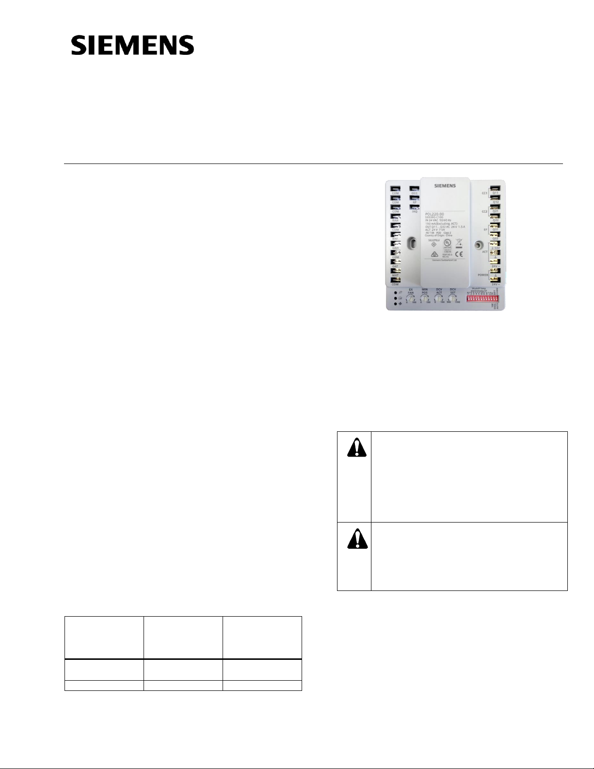
Product Description
The Economizer Controller allows the use of
unconditioned outside air to cool a building. The
Free Cooling air determination is based on customer
temperature and humidity selections, as well as
optional Demand Control Ventilation (DCV)
strategies with CO2 level selection.
Features
• Economizer control provides “free cooling”
based on single or dual dry bulb temperature, or
combination temperature + humidity sensors.
• Wide temperature shut-off setpoint range
selection and Btu/lb selection range selectable
by DIP switches.
• Potentiometers allow accurate adjustment of
DCV, exhaust fan levels, and minimum damper
position.
• Versions with remote minimum position damper
adjustments accept either 0 to 10 Vdc or 135
Ohm potentiometer signals.
• Used with Siemens OpenAir® damper actuators.
• Flexible sensor inputs accept 10K or 3K
standard NTC sensors, or Siemens QFM2160U
combination temperature/humidity 0 to 10V
sensor for enthalpy control.
• LED Indication when in Free Cooling operation,
DCV operation and exhaust fan operation as
well as during sensor failure.
• Quick installation and easy commissioning.
• Two-stage cooling control.
• Occupancy input with default capability.
• Quick connect I/O with 1/4” spade connections.
• Anti-freeze protection.
• Brownout protection.
Product Numbers
Economizer
Controller
Single
Economizer
Controller
Multi-pack (20)
Remote
Potentiometer
Input Type
POL220.05
POL220.00
BSG61
(0-10 Vdc)
POL220.10
POL220.15
LVC2 (135Ω)
Item Number 125-1902, Rev. GA
Contents
• Economizer Controller
• Two No. 6 3/4” self-tapping screws
Accessory
985-960 Jumper Accessory
Warning/Caution Notations
CAUTION/ATTENTION
Equipment damage or loss of data may
occur if you do not follow a procedure as
specified.
Risque de dégâts matériels ou de perte de
données, en cas de non-respect des
procédures à suivre.
WARNING/AVERTISSEMENT
Personal injury may occur if you do not
follow a procedure as specified.
Risque de blessures graves en cas de
non-respect des procédures à suivre.
Prerequisites
For proper Economizer Controller operation, read
this User Guide carefully, and follow the instructions
in the Economizer Controller Start-up/
Commissioning Mode section. Failure to do so may
result in damage to the product or create a
hazardous condition. Installation of this controller
must be performed by a trained HVAC service
technician.
Page 2

Document No. 125-1902
User Guide
June 26, 2018
Page 2 of 16 Siemens Industry, Inc.
Basic Economizer Control Modes
1. Control Mode 1: Fixed Dry-bulb
(Single dry-bulb)
Outside air and mixed air temperature sensors
are used.
2. Control Mode 2: Differential Dry-bulb
(Dual Dry-Bulbs)
Outside air, return air, and mixed air
temperature sensors are used.
3. Control Mode 3: Combination Fixed Enthalpy
and Fixed Dry-bulb Control
Outside air temperature and humidity sensors,
and mixed air temperature sensors are used.
4. Control Mode 4: Combination of Differential
Enthalpy and Fixed Dry-bulb
Outside air temperature and humidity sensors,
return air temperature and humidity sensors,
and mixed air temperature sensors are used.
Specifications
Electrical Ratings:
Input Voltage: 24 Vac ±25%; 50/60 Hz (Class 2).
Nominal Power Consumption (at 24 Vac, 60 Hz):
4 VA.
Relay Contact Rating at 30 Vac (maximum power
from Class 2 input only): 1.5A run, 3.5A inrush.
NOTE:
All inputs and outputs must be 24 Vac Class 2.
Ambient Ratings:
Temperature: -40°F to 149°F (-40°C to 65°C).
Humidity: 5 to 95 percent RH (non-condensing).
Inputs:
Combination Temperature/Humidity Sensor
(QFM2160U): 5-wire (18, 20, or 22 AWG cable)
connection.
Dry Bulb Temperature Sensor 10K Ohm Type II
NTC (QAM2030.010) or 3K NTC: 2-wire
(18, 20, or 22 AWG cable) connection.
DCV (CO2) Sensor (QPA2000): 3- wire
(18, 20, or 22 AWG cable)
0 to 10 Vdc control signal
Outputs:
Actuator (GCA151.1P GMA151.1P, GQD151.1P):
4-wire (18 AWG)
Actuator Signal: 2 to 10 Vdc.
Actuator Input Resistance: 100K ohm.
The controller provides 7 VA max. to operate the
damper actuator.
Exhaust Fan: Contact closure.
Auxiliary Equipment:
• RDY2000 Commercial Thermostat
• LVC2 (135 Ω) Control Board for remote minimum
damper positioning (POL220.10 and POL220.15)
• BSG61 (0-10 Vdc) for remote minimum damper
positioning (POL220.00 and POL220.05)
Wire the electrical connections using 1/4” female,
insulated spade connections.
Approvals:
UL listed per UL873.
CE
RCM
cUL Listed per CSA – C22.2 No. 24
Suitable for plenum installation
UL/NEMA Type 1
Dimensions: 5.10” × 4.70” × 1.10”
(130 mm × 120 mm × 28 mm)
Weight: 0.49 lbs (221 g)
Required Tool
Phillips Screwdriver
Expected Installation Time
15 minutes
Installation
Mount the controller to sheet metal ductwork or a
panel using two self-tapping screws (provided). The
mounting location must protect the controller from
the elements and ultraviolet rays.
Page 3
Document No. 125-1902
User Guide
June 26, 2018
Siemens Industry, Inc. Page 3 of 16
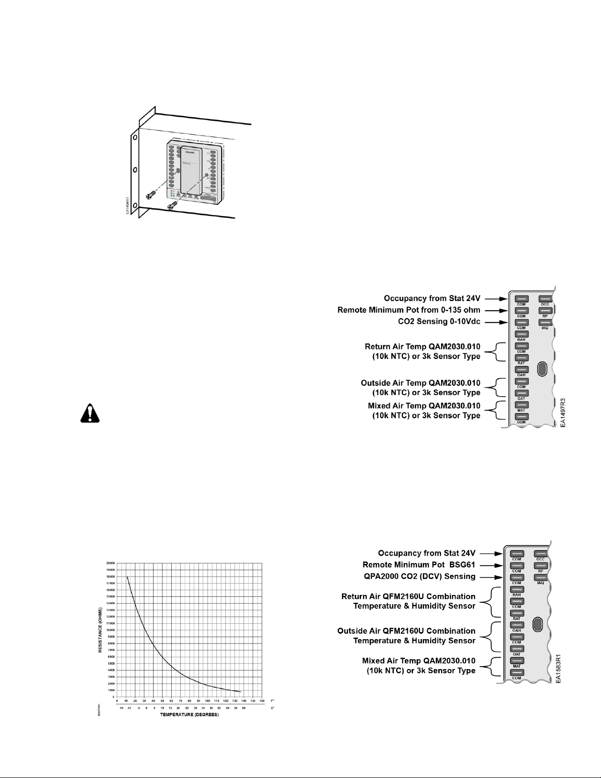
Figure 1. Controller Mounted to Ductwork.
Outdoor, Return Air, and Mixed Air
Sensor Operating and Mounting
Instructions
Location and Mounting
The Economizer Controller accepts signals from
either the QAM2030.010 (10K, Type II) dry bulb
temperature sensor, or 3K NTC temperature sensor.
It provides single or differential temperature based
economizer control or the QFM2160U combination
temperature/humidity sensor for single or dual
enthalpy-based economizer control.
CAUTION/ATTENTION:
Do not mix sensors.
Temperature sensors must all be either
10K Ohm Type II NTC, or 3K NTC.
Ne mélangez pas de détecteurs.
Les détecteurs de température doivent
tous être l'un ou l'autre le Type II d'Ohm
de 10 Ko NTC, ou 3 Ko NTC.
For differential dry bulb operation, use two
QAM2030.010 (10K Type II NTC) or 3K NTC
temperature sensors.
Figure 2. 3K NTC Curve.
NOTE: 3K NTC sensors must follow this curve.
Sensor Mounting
1. Mount the sensor in any orientation, exposing it
to freely circulating air, using the two mounting
screws provided with the sensor. Choose a
location that protects it from rain, snow, and
direct sunlight.
2. Connect the appropriate Type II NTC 10K or 3K
sensor for:
o Outside Air: Connect to the OAT and COM
terminals of the device.
o Return Air (Differential): Connect to the RAT
and COM terminals of the device.
o Mixed Air: Connect to the MAT and COM
terminals of the device.
Figure 3. Type II NTC 10K or 3K Sensor Connections.
3. Connect the QFM2160U Combination
Temperature/Humidity sensor for Enthalpy
control.
o Outside Air: Connect to the OAT, COM, and
OAH terminals of the device.
o Return Air (Differential): Connect to the
RAT, COM, and RAH terminals of the
device.
Figure 4. QFM2160U Combination
Temperature/Humidity Sensor Connections.
Page 4
Document No. 125-1902
User Guide
June 26, 2018
Page 4 of 16 Siemens Industry, Inc.
NOTE: QFM2160U Combination Temperature/
Humidity Sensors must be powered by an
external 24 Vac power supply.
CO2 Sensor – Demand Control
Ventilation (DCV)
1. Mount the QPA2000 CO2 Sensor in an area with
unobstructed air circulation. See QPA…Series
Indoor Air Quality Room Sensors Installation
Instructions (129-435).
2. Connect the sensor to the IAQ and COM
terminals of the controller. See Figure 4.
NOTE: CO2 sensors must be powered by an
external 24 Vac power supply.
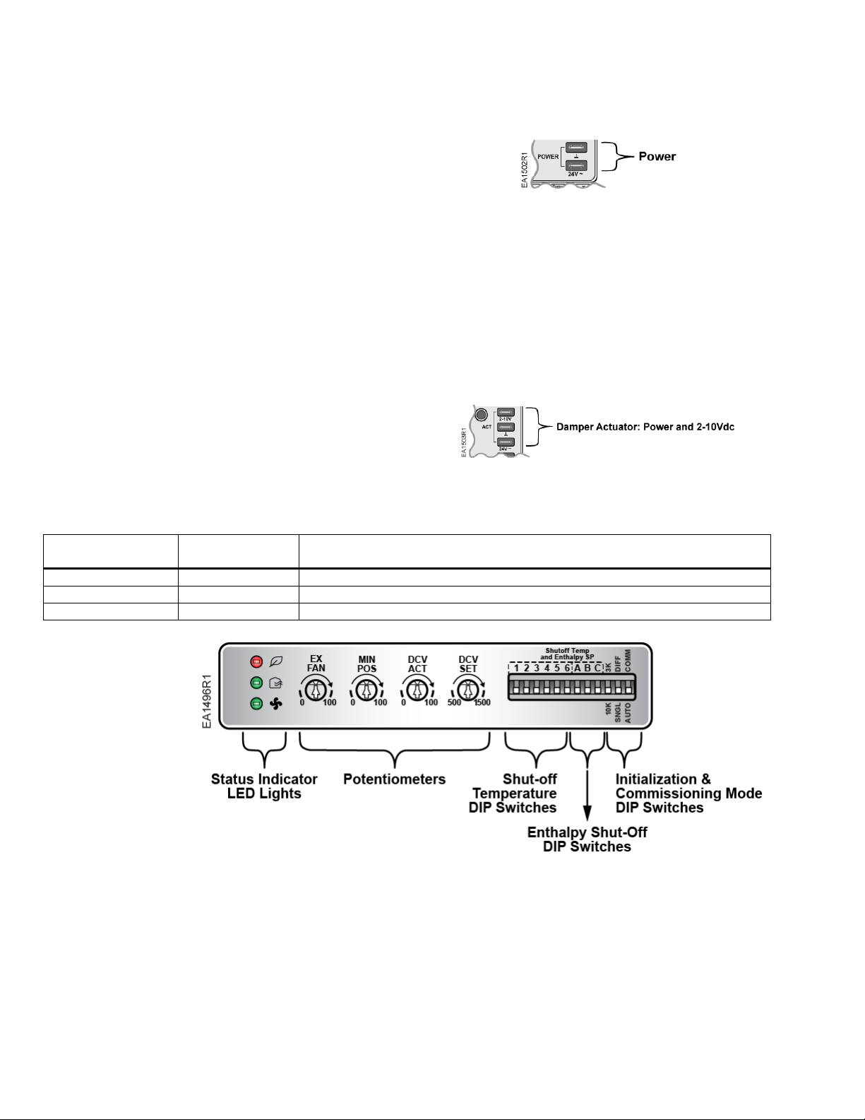
Powering the Economizer
Controller
To power the Economizer Controller, connect a
24 Vac external power supply source.
Figure 5. Connecting to Power Supply Source.
Damper Actuator Connection to the
Economizer Controller
1. Connect the appropriate Siemens OpenAir
Damper Actuator to the controller actuator input
as shown.
2. Select the appropriate modulating (2 to 10 Vdc)
spring return damper actuator to operate the
Economizer damper. See Table 1.
Figure 6. Damper Actuator Connections.
Table 1. Damper Actuator Selection.
Damper Actuator
Part Number
Torque Rating
Description
GQD151.1P
20 lb-in
Spring Return, 2 to 10 Vdc Signal, Plenum-rated
GMA151.1P
62 lb-in
Spring Return, 2 to 10 Vdc Signal, Plenum-rated
GCA151.1P
160 lb-in
Spring Return, 2 to 10 Vdc Signal, Plenum-rated
Figure 7. Economizer Control Adjustments.
Page 5

Document No. 125-1902
User Guide
June 26, 2018
Siemens Industry, Inc. Page 5 of 16
Economizer Controller
Startup/Commissioning Mode
Factory default settings:
All DIP switches are in the OFF (down position).
NOTE:
Use a small, flat-blade screwdriver to select DIP
switches. Ensure that the switches are fully in the
ON or OFF position.
All potentiometers are in the middle position (arrow
pointing upwards).
Initialization
1. Connect the sensor inputs and other auxiliary
equipment.
2. Use the DIP switch to select a 3K or 10K sensor
(see Figure 7).
3. Use the DIP switch to select Single (SNGL) or
Differential (DIFF) mode (see Figure 7).
4. Apply power to the controller (see Figure 5).
5. The controller will perform up to a 20-second
auto detection to determine the type of sensor
input(s).
If you experience a transient power failure during
initialization, the compressors will not suddenly
restart because the outputs are deactivated.
Commissioning Mode
This Commissioning mode (COMM) adjusts the
Minimum Position of the outside air damper. In the
Commissioning mode, the damper will be overridden
by Effective MIN POS, or DCV ACT, whichever is
greater.
Effective MIN POS is determined by either the
onboard MIN POS potentiometer or the Remote MIN
POS potentiometer:
Move the DIP switch on the bottom of the controller
to the COMM position (see Figure 7) to enter the
Commissioning mode. When the Free Cooling LED
and DCV LED blink red, this indicates that the
controller is in the Commissioning mode. CC1 and
CC2 are energized in the Commissioning mode, and
the exhaust fan responds to the outside air damper.
Determining Required Airflow
The Consulting Engineer defines the minimum
damper position by the minimum outdoor airflow
required in the building during the occupied period.
To determine the minimum amount of outside air to
bring in the building, use these basic guidelines:
• The OA rate can be calculated by this formula:
OA
% =
MAT−RAT
OAT−RAT
A minimum 10°F temperature differential
between OA and RA must be maintained;
otherwise, this formula doesn’t work well.
OR
• An airflow measuring station can be used to
directly tune the outdoor airflow volumetric rate
to designed value. OA rate can be calculated
from formula 𝑂𝐴% =
OAV
SAV
=
OAV
OAV+RAV
, where
minimum differential temperature between OA
and RA is not required.
Setting Minimum Position in Commissioning
Mode
If a Remote Positioning Potentiometer is being
used:
1. Turn the MIN POS potentiometer to the fully
closed, 0 position.
2. Turn the DCV ACT potentiometer to the fully
closed, 0 position
3. Adjust the Remote MIN POS Potentiometer until
the designed OA flow rate is met.
4. After the Remote MIN POS Potentiometer
adjustment is complete, turn the DCV ACT
potentiometer until designed DCV OA flow rate
is met. The DCV ACT setting should be greater
than the Remote MIN POS Potentiometer
setting.
5. When these adjustments are completed, set
the DIP switch to AUTO to resume normal
operation.
If the onboard MIN POS Potentiometer is being
used:
1. Turn the Remote MIN POS Potentiometer to the
fully closed, 0 position.
2. Turn the DCV ACT potentiometer to the fully
closed, 0 position,
3. Turn the MIN POS potentiometer until designed
OA flow rate is met.
4. After MIN POS adjustment is complete, turn the
DCV ACT potentiometer until designed DCV OA
flow rate is met. The DCV ACT should be
greater than MIN POS.
5. After all MIN POS and DCV ACT adjustments
are completed, set the DIP switch to AUTO to
resume normal operation.
Page 6

Document No. 125-1902
User Guide
June 26, 2018
Page 6 of 16 Siemens Industry, Inc.
Selecting the Shut-off Temperature and
Enthalpy Setpoint
The damper will be open and will allow for free
cooling below the temperature shut-off setpoint
selected from one of the six DIP switches located on
the bottom right corner of the controller cover (see
Figure 7).
The numbered DIP switches correspond to the shutoff temperature values (see Table 2). When all of the
DIP switches are in the down position and no
number is selected (factory default), the default
temperature shut-off setpoint value is 75°F.
Table 2. Shut-off Temperature Values.
Default
1 2 3 4 5
6
75°F
50°F
55°F
60°F
65°F
70°F
80°F
For Economizer operation based on both
temperature and humidity, the enthalpy shut-off
setpoint value may be selected from the following
lettered DIP switches. When the three DIP switches
are in the down position, the default enthalpy shutoff value is 28 Btu/lb.
Table 3. Enthalpy Shut-Off Values.
Default
A B C
28 Btu/lb
22 Btu/lb
24 Btu/lb
26 Btu/lb
For further assistance in determining these shut-off
setpoint values, see ASHRAE 90.1.2014 for a
guideline for shutoff control types for specific climate
zones.
Selecting Single or Differential
(Dual) Sensors
Basic Economizer Control Modes
Control Mode 1: Fixed Dry-bulb (Single Dry-Bulb)
• OA temperature sensor and MA temperature
sensor are used.
• Set the DIP switch to SNGL (single) mode. See
Figure 7.
• The outside-air dry-bulb temperature is
compared to a shut-off dry-bulb temperature. If
the outside-air dry-bulb temperature is below the
shut-off dry-bulb temperature, then the outside
air is used to meet all or part of the cooling
demand.
Control Mode 2: Differential Dry-bulb (Dual DryBulbs)
• OA temperature sensor and RA temperature
sensor, MA temperature sensors are used.
• Set the DIP switch to DIFF (Differential) mode.
See Figure 7.
• The outside-air dry-bulb temperature is
compared with the return-air dry-bulb
temperature. If the outside-air dry-bulb
temperature is less than the return-air dry-bulb
temperature, then the outside air is used to meet
all or part of the cooling demand.
Control Mode 3 - Combination Fixed Enthalpy and
Fixed Dry-bulb Control
• OA temperature and Humidity sensor, and MA
temperature sensor are used.
• Set the DIP switch to SNGL (Single) mode. See
Figure 7.
• Determine the shut-off setpoint by a combination
of two parameters:
- Enthalpy shut-off SP
- Dry-bulb shut-off SP
• Determine if the outside air can be used for Free
cool:
If the outside-air enthalpy is lower than the shutoff enthalpy setpoint, and the outside air dry bulb
temperature is lower than the shut-off dry bulb
setpoint, then the outside air can be used.
Control Mode 4 - Combination of Differential
Enthalpy and Fixed Dry-bulb
• OA temperature and humidity sensor, and return
temperature and humidity sensor, and MA
temperature sensor are used.
• Set the DIP switch to DIFF (Differential) mode.
See Figure 7.
• Determine if outside air can be used for Free
cooling: If outside-air enthalpy is lower than the
return air enthalpy, and the outside air dry bulb
temperature is lower than the dry bulb
temperature shut- off setpoint, then outside air
can be used.
Demand Control Ventilation Setpoint
(DCV Only)
The controller will modulate the outside air damper
based on the CO2 level through the ppm value
selected by the DCV SET potentiometer between
the range of 500 and 1500 ppm, on the controller, as
shown in Figure 7.
To disable the DCV, turn the DCV ACT
potentiometer counter-clockwise to 0%.
If a CO2 sensor is not used with the controller, the
OA damper will modulate based on the Free Cooling
logic.
If the CO2 sensor has failed, the damper will be
controlled by the Free Cooling logic.
Page 7

Document No. 125-1902
User Guide
June 26, 2018
Siemens Industry, Inc. Page 7 of 16
Exhaust Fan Operation and Setting
Figure 8. Relay Connection.
The exhaust fan contacts are 24V dry contacts only,
and are labeled Q31 and Q32. An external line
voltage contactor is required to operate the exhaust
fan.
If the EX FAN potentiometer is turned fully counterclockwise to 0%, the EX FAN feature is disabled.
This feature allows the exhaust fan operation to be
disabled instead of being operated at constant ON.
The exhaust fan shut-off point is selected by setting
the EX FAN potentiometer to the desired level. See
Figure 7.
When the damper position reaches the exhaust fan
setpoint, the exhaust fan relay will be energized. A
Green exhaust fan LED indicates that the exhaust
fan is ON.
Cooling Stage Operation
Figure 9. Cooling Stage Operation.
The Economizer Controller accepts inputs for singleand two-stage cooling inputs, and reroutes to the
RTU through the relay connection CC1 and CC2.
The operation of the cooling stages is determined by
the availability of Free Cooling provided by the
economizer operation mode. SeeTable 4.
Based on the use of Free Cooling, the operating
modes are as follows:
• Y1 is Stage 1 Cooling Demand.
• Y2 is Stage 2 Cooling Demand.
• Free Cooling is always the first cooling stage.
• The Cool Stage 1 call from the Commercial
Thermostat (Y1) energizes the CC1 input to the
Economizer Controller.
• The Cool Stage 2 call from the Commercial
Thermostat (Y2) energizes the CC2 input to the
Economizer Controller.
Table 4. Cooling Stage I/O Logic.
Economizer
Y1
Thermostat
Y2
Thermostat
Cooling
Stage 1
Cooling
Stage 2
OFF
ON
ON
ON
ON
OFF
ON
OFF
ON
OFF
OFF
OFF
OFF
OFF
OFF
ON
ON
ON
ON
OFF*
ON
ON
OFF
OFF
OFF
ON
OFF
OFF
OFF
OFF
* If OAT<56°F, then Relay 2 is always OFF to
disable Cooling Stage 2. Otherwise, if both stages of
cooling (Y1 and Y2) are ON for more than 5
minutes, Y2 remains ON, and the OAT is greater
than 56°F, then Relay 2 will energize to allow Y2
pass-through to enable Cooling Stage 2.
Remote Positioning Potentiometer
BSG61, 0 to 10 Vdc for POL220.00 and
POL220.05
The BSG61 Remote Positioning Potentiometer can
be used to remotely set the minimum damper
position and connect the RP and COM terminals of
the device.
Figure 10. RP and OCC Terminals.
This input offsets the damper minimum position
setting (MIN POS).
NOTE: The BSG61 Remote Positioning
Potentiometer must be powered by an
external 24 Vac power supply.
When the remote potentiometer is installed, set the
MIN POS potentiometer to 0%; the damper position
will receive positioning signals from the BSG61
Remote Potentiometer.
Page 8

Document No. 125-1902
User Guide
June 26, 2018
Page 8 of 16 Siemens Industry, Inc.
LVC2, 135 Ohm for POL220.10 and POL220.15
The LVC2 Control Board can be used to remotely
set the minimum damper position and connect the
RP and COM terminals of the device.
Figure 11. RP and OCC Terminals.
This input offsets the damper minimum position
setting (MIN POS).
When the remote potentiometer is installed, set the
MIN POS potentiometer to 0%; the damper position
will receive positioning signals from the LVC2
Control Board.
Occupancy Input
The Economizer Controller can input an occupancy
signal from the commercial thermostat on inputs
OCC and COM. If an occupancy signal is not
available, order Jumper Accessory 985-960, and
connect to these inputs to default the occupancy
status to ON.
When OFF, the minimum damper position is 0%.
LED Fault Detection and Diagnostics
Table 5. LED Pattern Summary.
Status
Free Cooling
LED
Demand Control
Ventilation LED
Exhaust Fan
LED
Commissioning mode
Red Blinking
Red Blinking
Power-Start-up
Orange
Orange
Green
MA/OA Sensor failure in SNGL mode
Red On
MA/OA/RA Sensor failure in DIFF mode
Red On
MIN POS potentiometer Failure
Red On
CO2 Sensor failure when DCV is enabled
Red On
DCV SET/DCT ACT potentiometer failure
Red On
DCV SET position is inappropriate
Fast Red Blinking
Brownout
Red On
Red On
Failure to detect valid FC Sensor mix during
initialization
Red On
Application
Figure 12. Connected Economizer System Components Location Example.
Page 9

Document No. 125-1902
User Guide
June 26, 2018
Siemens Industry, Inc. Page 9 of 16
Wiring Guide
Figure 13. Two-Stage Cooling System with Single Dry-Bulb Changeover Control Mode.
Page 10

Document No. 125-1902
User Guide
June 26, 2018
Page 10 of 16 Siemens Industry, Inc.
Figure 14. Two-Stage Cooling System with Dual Dry-Bulb Changeover Control Mode.
Page 11

Document No. 125-1902
User Guide
June 26, 2018
Siemens Industry, Inc. Page 11 of 16
Figure 15. Two-Stage Cooling System with Single Enthalpy Changeover Control Mode.
Page 12

Document No. 125-1902
User Guide
June 26, 2018
Page 12 of 16 Siemens Industry, Inc.
Figure 16. Two-Stage Cooling System with Dual Enthalpy Changeover Control Mode.
Page 13

Document No. 125-1902
User Guide
June 26, 2018
Siemens Industry, Inc. Page 13 of 16
Figure 17. Optional CO2 Sensor and Remote Potentiometer LVC2, 135 Ohm.
Figure 18. Optional CO2 Sensor and Remote Potentiometer BSG61, 0 to 10 Vdc.
The installation is now complete.
Page 14

Document No. 125-1902
User Guide
June 26, 2018
Page 14 of 16 Siemens Industry, Inc.
Dimensions
Figure 19. Dimensions in Inches (Millimeters).
Troubleshooting
WARNING/AVERTISSEMENT:
Do not open the actuator.
Ne pas ouvrir le servomoteur !
Symptom
Reason
Solution
The Economizer Controller/
Mechanical
Cooling is not operating
No input power
Use a multi-meter to check if there is 24 Vac +/- 25% (18 Vac – 30 Vac) at
the POWER terminals.
If there is no voltage or if the voltage is significantly low, check the
transformer output voltage at the RTU. If 24 volts is not present at the
transformer secondary side, check the primary line voltage to the
transformer.
If the line voltage is not present at the transformer primary side, check the
primary power to the RTU, fuses, circuit breaker, and so on.
Brownout
If voltage is below 18 Volts, the Economizer Controller may be in Brownout
Protection mode. This mode disables all of the relay outputs.
When the power is back to 18 Vac or higher, the Economizer Controller and
RTU will operate normally.
Y1/Y2 signal is missing
from the thermostat
Mechanical Cooling doesn’t run until there is cooling demand (Y1/Y2 Active).
Check the wiring from CC1, Q11 and CC2, Q21 terminals to the commercial
thermostat. 24V should present between CC1.Q11/CC2.Q21 and COM.
24 Vac~ and 24 Vac ┴
are incorrectly wired
24 Vac power supply has polarity when all devices are powered by the same
24 Vac transformer; reversing polarity may cause a short circuit that can
damage the system.
Follow the transformer polarity mark; check the wring of 24V~ (or G or 24V+)
and ensure that they are tied to the same polar of 24 Vac power supply;
while checking the wiring of ┴ (or G0 or 24V- or COM) and ensure that they
are all tied to another polar of 24 Vac power supply.
Page 15

Document No. 125-1902
User Guide
June 26, 2018
Siemens Industry, Inc. Page 15 of 16
Symptom
Reason
Solution
Free Cooling LED is solid
RED
Mixed Air (MA) sensor error
Check the MA sensor, it must be either a 10K Type II NTC, or 3K NTC
sensor.
Outside Air (OA)/Return Air
(RA) sensor error
Check the OA sensor. If in DIFF mode, check the RA sensor too. The
following sensor signals are valid:
• 10K Type II NTC temperature
• 3K NTC temperature
• 0–10V temperature and 0–10V humidity
• 10K Type II NTC temperature and 0-10V humidity
• 3K NTC temperature and 0-10V humidity
In Differential (DIFF) mode, OA and RA sensors must be of the same
sensor type.
MIN POS potentiometer has
been damaged by excessive
force
Check if MIN POS potentiometer has been damaged; if so, replace the
Economizer Controller.
Sensor Auto Detection error
Ensure that the sensors have been correctly wired prior to controller
power-up. Power-up the active sensors first, or power-up the controller
and the active sensors simultaneously. Otherwise, the controller may not
capture the sensor type in time.
Don’t change the DIP switch settings (10K/3K or SNGL/DIFF) when the
controller is running. The controller must be rebooted after any changes to
the sensor or sensor setting for the new sensor configuration to be
implemented.
DCV LED is solid RED
CO2 sensor error
Check the CO2 sensor signal; the valid signal must be 0-10V.
DCV ACT or DCT SET
potentiometer has been
damaged by excessive force
Check if DCV ACT or DCT SET potentiometer has been damaged by
excessive force; if so, replace the Economizer Controller.
DCV ACT is not being
turned to the 0 position
The DCV feature should not be enabled, but it was not turned off. Adjust
the DCV ACT potentiometer to full CCW position if you are not using
DCV.
Exhaust Fan LED is not
working
The Ex FAN potentiometer
hasn’t been set up correctly,
or has been damaged by
excessive force.
In its full CCW position, the EX FAN control is disabled; therefore, the
Exhaust Fan LED is OFF, and the EF relay is inactive. To use this feature,
the EX FAN potentiometer must be turned to a non-zero position.
If the EX FAN control is enabled, but the Exhaust Fan doesn’t work
correctly, check if the EX FAN potentiometer has been damaged. If so,
replace the Economizer Controller.
Both Free Cooling and DCV
red LEDs are blinking
The Economizer Controller
is set to COMM mode
The Economizer Controller is set to COMM mode, and must be set back
to AUTO mode to resume normal operation.
DCV red LED is blinking
The DCV feature is enabled,
but the DCV ACT
potentiometer is improperly
set.
Ensure that the DCV ACT is greater than the MIN POS setting.
The controller has no alarm,
but the Free Cooling LED
never turns on even though
the OA seems to be suitable
for Free Cooling
Shut-off SP setting error
The shut-off temperature and/or enthalpy setpoint is incorrectly set up.
Consult an HVAC professional to set up the shut-off setpoint correctly.
OA temp is too low
The OAT is too low; therefore, there is no cooling demand. This could
possibly enable anti-freeze protection.
OA temp is too high or too
humid
In DIFF mode, even though OA temperature is lower than RA
temperature, if both OA and RA temperatures exceed the high limit, Free
Cooling will turn off.
In Differential Enthalpy control mode, even though OA enthalpy is lower
than RA enthalpy, if both OA and RA enthalpy exceed the high limit, Free
Cooling will turn off.
Page 16

Document No. 125-1902
User Guide
June 26, 2018
Information in this publication is based on current specifications. The company reserves the right to make changes in specifications and models as
design improvements are introduced. OpenAir is a registered trademark of Siemens Schweiz AG. Other products or company names mentioned herein
may be the trademarks of their respective owners. © 2018 Siemens Industry, Inc.
Siemens Industry, Inc.
Building Technologies Division
1000 Deerfield Parkway
Buffalo Grove, IL 60089
USA
+ 1 847-215-1000
Your feedback is important to us. If you have
comments about this document, please send them
to sbt_technical.editor.us.sbt@siemens.com
Document No. 125-1902
Printed in the USA
Page 16 of 16
• Link to EULA and OSS Read Me File:
http://w3.usa.siemens.com/buildingtechnologies/us/en/legal_information/Pages/eula-and-oss.aspx
FCC NOTE:
This device complies with Part 15 of the FCC Rules. Changes or modifications not expressly approved by Siemens
Industry Inc. could void the user’s authority to operate the equipment.
Operation is subject to the following two conditions:
(1) This device may not cause harmful interference, and
(2) this device must accept any interference received, including interference that may cause undesired operation.
Note: This equipment has been tested and found to comply with the limits for a Class B digital device, pursuant to part
15 of the FCC Rules. These limits are designed to provide reasonable protection against harmful interference in a
residential installation. This equipment generates, uses and can radiate radio frequency energy and, if not installed and
used in accordance with the instructions, may cause harmful interference to radio communications. However, there is no
guarantee that interference will not occur in a particular installation. If this equipment does cause harmful interference to
radio or television reception, which can be determined by turning the equipment off and on, the user is encouraged to try
to correct the interference by one or more of the following measures:
—Reorient or relocate the receiving antenna.
—Increase the separation between the equipment and receiver.
—Connect the equipment into an outlet on a circuit different from that to which the receiver is connected.
—Consult the dealer or an experienced radio/TV technician for help.
 Loading...