

Siemens OpenAir GDE132.1P, OpenAir GLB, OpenAir GDE131.1P, OpenAir GDE136.1P, OpenAir GDE131.1P/B Technical Instructions
...Page 1
Technical Instructions
Document No. 155-188P25
EA GDE/GLB-2
December 26, 2007
OpenAir™ Electric Damper Actuator
GDE/GLB Series
Non-spring Return Rotary
24 Vac Floating Control
Description
Features
Application
Product Numbers
Torque Standard
GDE131.1U
GDE131.1U/B (24 pk)
GDE131.1P
GDE131.1P/B (24 pk)
44 lb-in
(5 Nm)
88 lb-in
(10 Nm)
GDE131.1Q
GDE131.1Q/B (12 pk)
GDE131.1N
GDE131.1N/B (24 pk)
GDE131.1T
GDE131.1T/B (24 pk)
GLB131.1P
GLB131.1Q
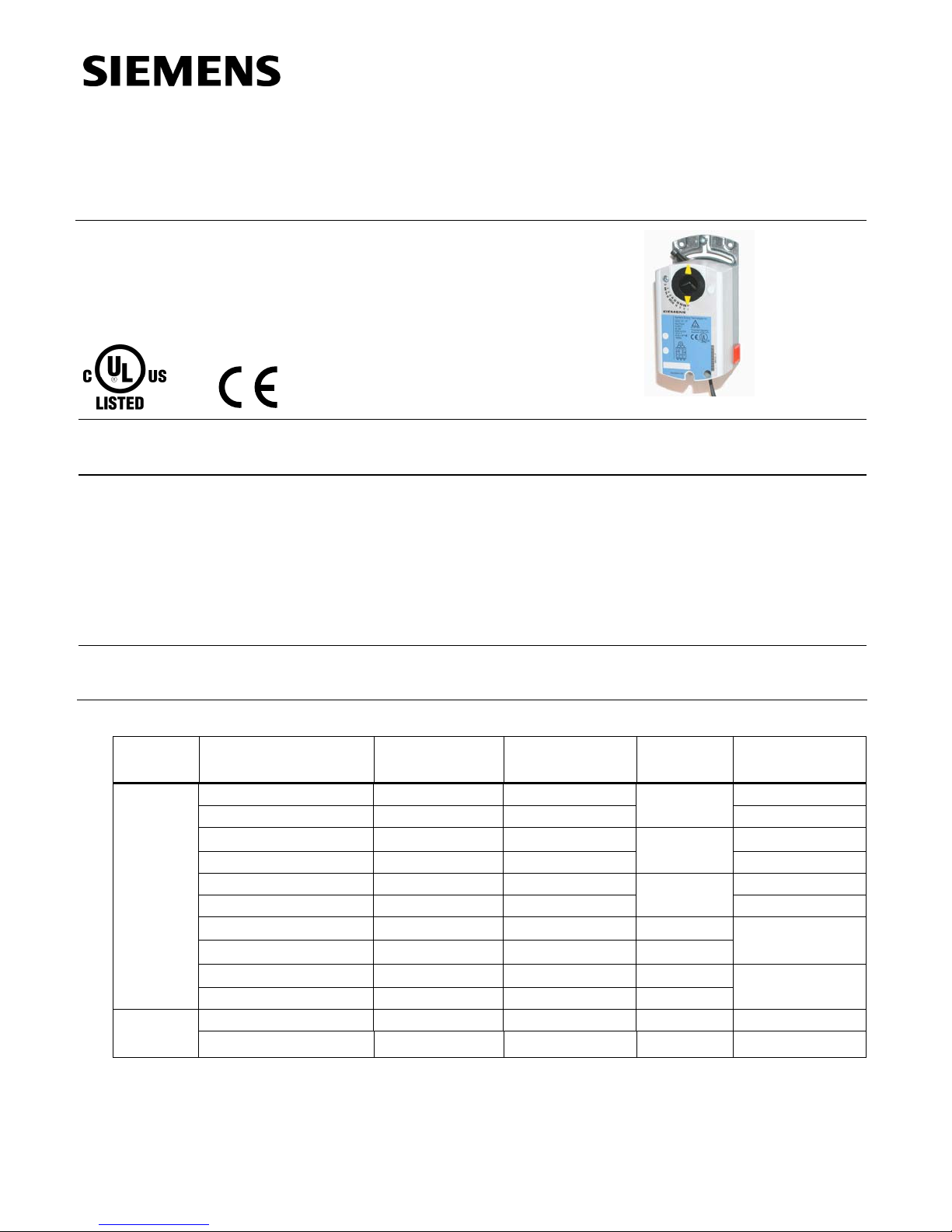
OpenAir direct coupled 24 Vac non-spring return rotary electric actuators are
designed for floating control of dampers.
• Compact, lightweight design
• Manual override
• Standard and plenum models available
• Feedback potentiometer models available
• cUL and UL listed, CE certified
• Independently adjustable dual auxiliary switches available
These actuators are used in constant or variable air volume installations for control
of HVAC dampers requiring up to 44 lb-in (5 Nm) or 88 lb-in (10 Nm) of torque.
Table 1.
With
Potentiometer
— —
— —
GDE132.1P GDE136.1P
— —
— —
— —
— —
— — —
— — —
— — —
GLB132.1P GLB136.1P Plenum
— — 6 ft length
Dual Auxiliary
Switches Only
Pre-Cabled No Cables
Standard
Plenum
6 ft length
—
Post Header AMP
Terminal Strip
—
—
—
—
—
—
—
—
Siemens Building Technologies, Inc.
Page 2

Technical Instructions OpenAir Non-Spring Return Rotary Electric Damper Actuator
Document No. 155-188P25
December 26, 2007
24 Vac Floating Control
Specifications
Operating voltage (G–Y1 or G–Y2) 24 Vac +20%, -15%
Frequency 50/60 Hz
Power supply
Equipment rating
Power consumption 2.3 VA
Rating Class 2 according to UL, CSA
Class III per EN60730
Auxiliary features
Feedback potentiometer (GDE/GLB132.1P)
Sliding contact (P2) 0 to 1000 ohm < 10 mA
Load < 1W
Voltage UL-Class 2 (SELV/PELV for CE)
< 24 Vac/dc
Dual auxiliary switch contact rating
AC Rating 24 Vac/24 Vdc
4A resistive, 2A inductive
DC Rating 12 to 30 Vdc
DC 2A
Switch Range
Switch A 0° to 90° with 5° intervals
Recommended range usage 0° to 45°
Factory setting 5°
Switch B 0° to 90° with 5° intervals
Recommended range usage 45° to 90°
Factory setting 85°
Switching hysteresis 2°
Function
Torque
GDE 44 lb-in (5 Nm)
GLB 88 lb-in (10 Nm)
Runtime for 90° opening or closing
GDE 90 sec. at 60 Hz (108 sec. at 50 Hz)
GLB 125 sec. at 60 Hz (150 sec. at 50 Hz)
Nominal angle of rotation 90°
Maximum angular rotation 95°
Mounting
Shaft size: Minimum shaft length 3/4 inch (20 mm)
3/8 to 5/8 inch
EA1010R1
8 -16 mm
Housing
Enclosure NEMA Type 2
IP54 according to EN60529
GDE131.1N and GDE 131.1T NEMA1
Material Durable plastic
Gear lubrication Silicone-free
Page 2 Siemens Building Technologies, Inc.
1/4 to 1/2 inch
6 - 12.7 mm
Figure 1. Acceptable Shaft Sizes.
9/16 inch
15 mm
Page 3

OpenAir Non-Spring Return Rotary Electric Damper Actuator Technical Instructions
24 Vac Floating Control Document No. 155-188P25
December 26, 2007
Specifications, Continued
Ambient
conditions
Agency
certification
Conformity
for Plenum
Models
Miscellaneous
Accessories
Ambient temperature
operation -25°F to 130°F (-32°C to 55°C)
storage and transport -40°F to 158°F (-40°C to 70°C)
Ambient humidity (non-condensing) 95% RH
UL listed to UL873
cUL certified to Canadian Standard
C22.2 No. 24-93
In accordance with the directive set forth by the European Union for
Electromagnetic Compatibility (EMC) 89/336/EEC
Emissions standards EN 50081-1
Immunity standards EN 50082-2
Pre-cabled connection 18 AWG
Standard cable length 3 feet (0.9m)
Life cycle: Designed for over 60,000 full strokes and
a minimum of 1.5 million repositions at
rated torque and temperature
Dimensions 6.2" L × 2.8" W × 2.4" D× 2.4" D
(157 mm L × 71 mm W × 61 mm D)
Weight 1.06 lb. (0.48 kg)
NOTE: Neither the auxiliary switches nor feedback potentiometer can be added in
the field. Order the product number that includes these options.
See Table 1.
EA0695R1
ASK71.5 Allows a direct-coupled actuator to
provide an auxiliary linear drive.
Figure 2. Rotary to Linear.
Ea0696R1
Figure 3.
Rotary to Linear
with Bracket.
ASK71.6 Allows economical mounting of an OpenAir
actuator to a variety of surfaces. Should be used in
applications where the actuator can be rigid-surface
mounted and a linear stroke output is needed.
ASK76.1U Provides the connection between the
actuator and conduit.
NOTE: GDE131.1T and GDE131.1N are not
compatible with the ASK76.1U.
Figure 4.
EA0647R1
Conduit Adapter.
Siemens Building Technologies, Inc. Page 3
Page 4
Technical Instructions OpenAir Non-Spring Return Rotary Electric Damper Actuator
Document No. 155-188P25
24 Vac Floating Control
December 26, 2007
Accessories,
Continued
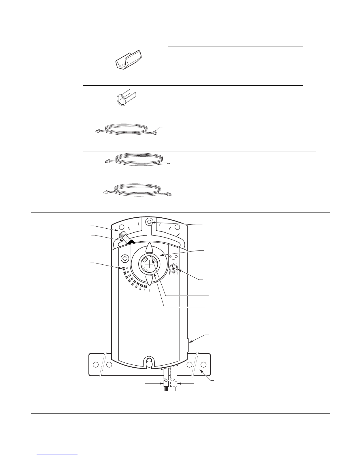
Actuator
Components
EA0807R1
Figure 5.
EA1060R1
Shaft Insert.
Figure 6. Shaft Guide Insert.
EA1246R1
Figure 7.
EA1251R1
Figure 8.
EA1248R1
Figure 9.
1
11
Terminal Plug
(To TEC)
ASK78.3U Shaft insert for use with 3/8-inch (8
to 10 mm) diameter shafts. (Included in box with
GDE/GLB Series). (Pkg/10)
NOTE: Factory installed 1/2-inch guide must
be removed prior to installation.
985-101P25 –Shaft guide insert, 1/2 inch 25 Pk
(Factory installed with GDE/GLB
Series).
985-132: Floating input cable for use only with the
Siemens Building Technologies, Inc.
Terminal Equipment Controller (TEC), 3 ft,
12 pk.
985-131: Floating input cable; 3 ft, 12 pk.
985-134: Daisy chain cable 12 ft, 12 pk.
985-135: Daisy chain cable 25 ft, 12 pk.
Legend
12
1. Base plate
2
EA0642R3
A B
80 70 60
Aux Switch
Adjustment
2010
50
90
45
90
34
Figure 10. Parts of the Actuator.
10
8,9
2. Positioning scale for angle of
rotation
3. Connection cables
4. Connection cables
7
6
5. Manual override
6. Coupling bushing
7. Factory installed 1/2-inch guide
5
8. Auxiliary switch A
9. Auxiliary switch B
10. Position indicator
11. Adjustment lever with locking
13
screw (4 mm hex)
12. Set screw for mechanical range
stop (4 mm hex)
13. Mounting bracket
Page 4 Siemens Building Technologies, Inc.
Page 5
OpenAir Non-Spring Return Rotary Electric Damper Actuator Technical Instructions
24 Vac Floating Control Document No. 155-188P25
December 26, 2007
Actuator Components, Continued
Terminal
Strip
Post Header
AMP
EA1094R1
GDE131.1N
EA1240R1
GDE131.1T
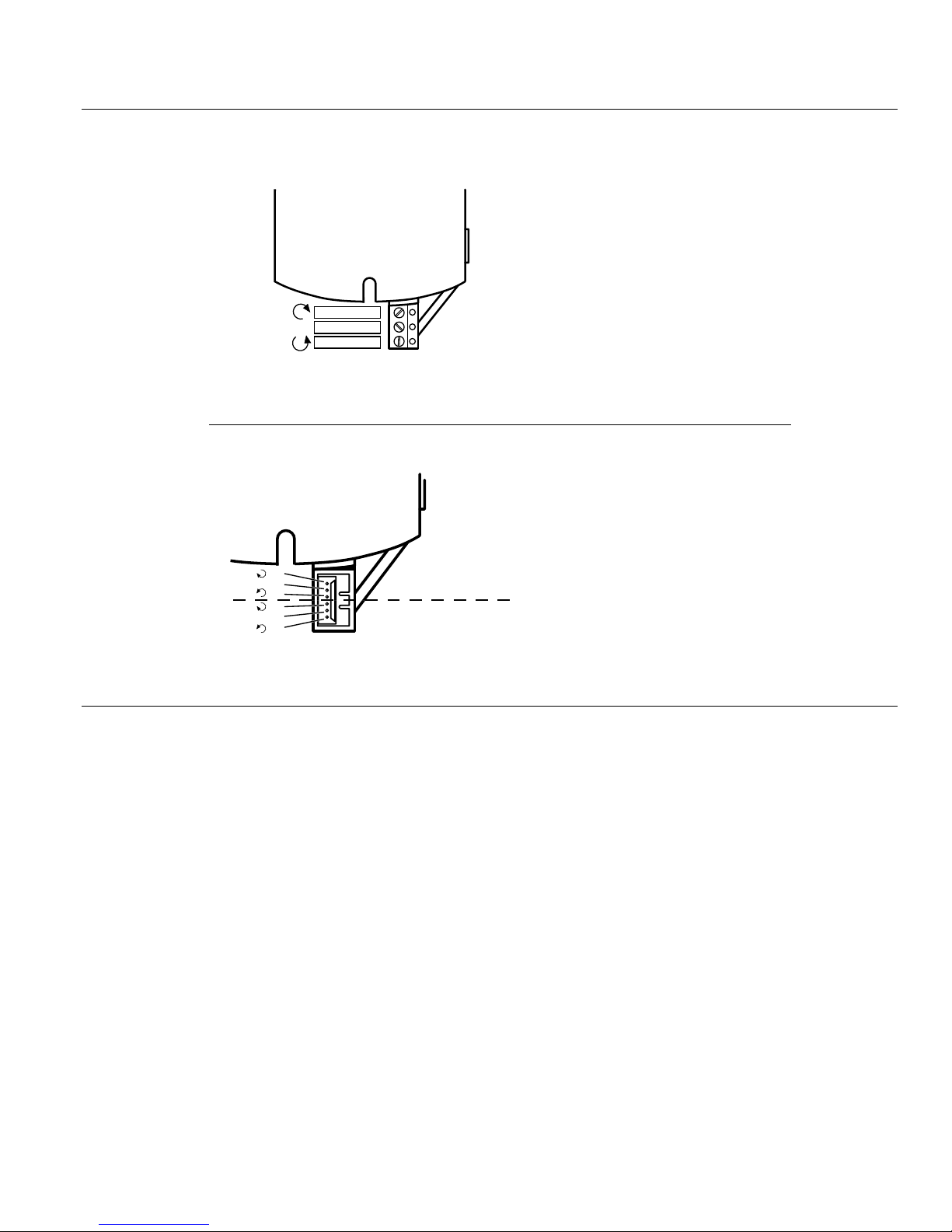
The GDE131.1T uses a Terminal
Strip connection for connection
purposes rather than the cable
connection.
GDE131.1T
NOTE: Wires are supplied by the
customer.
CW
Supply 24Vac
CCW
Figure 11.
GDE131.1N
The GDE131.1N model uses a Post
Header for connection purposes
rather than cable connections.
The Post Header has two identical
Y1
G
Y2
Y1
G
Y2
Input (Output)
Output (Input)
Figure 12.
sets of contacts.
NOTE: Cables are purchased
separately. See
Accessories.
Siemens Building Technologies, Inc. Page 5
Page 6
Technical Instructions OpenAir Non-Spring Return Rotary Electric Damper Actuator
Document No. 155-188P25
December 26, 2007
24 Vac Floating Control
Operation
A floating control signal controls the damper actuator. The actuator’s angle of rotation is
proportional to the length of time the signal is applied. A 24 Vac control signal to wires 1
and 6 (G-Y1) causes the actuator coupling to rotate clockwise. A 24 Vac control signal to
wires 1 and 7 (G-Y2) causes the actuator coupling to rotate counterclockwise.
To reverse the direction of rotation, the wires 6 and 7 (Y1 and Y2) can be interchanged.
In the event of a power failure or with no control voltage, the damper actuator holds its
position.
Life expectancy
Auxiliary switches
GDE/GLB136.1P
Sizing
An improperly tuned loop will cause excessive repositioning that will shorten the life of the
actuator.
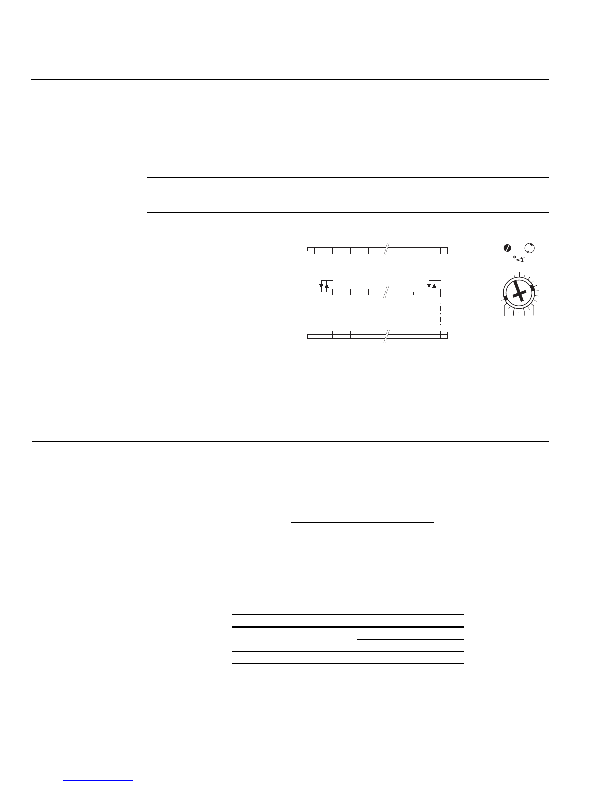
Figure 13 shows the adjustable switching values for the auxiliary switches A and B.
Actuator Scale:
clockwise
Adjustment range for
Switches A and B
Setting interval: 5°
Switching hysteresis: 2°
Actuator Scale:
counterclockwise
-2,5 0 10 20 30 70 80 90 92,5
AB
0 10 20 30 70 80
92,5 90 80 70
EA0640R1
60
20 10
90
-2,5
0
Figure 13. Adjustable Switching Values
A
B
2010
80 7060
AUX SWITCH
ADJUSTMENT
EA0636R2
50
for the Dual Auxiliary Switches.
NOTE: The auxiliary switch setting shafts rotate with the actuator. The scale is valid
only when the actuator is in the "0" position on clockwise motion.
Use the long arm of the
† to point to the position of switch A. Use the narrower
tab on the red ring to point to the position of switch B.
The type of actuator required depends on several factors.
2
1. Obtain damper torque ratings (ft-lb/ft
or Nm/m2) from the damper manufacturer.
2. Determine the area of the damper.
3. Calculate the total torque required to move the damper:
Total Torque =
4. Select the actuator type from Table 2.
1
Safety Factor: When determining the torque of an actuator required, a safety factor
should be included for unaccountable variables such as slight misalignments, aging
of the damper, etc. A suggested safety factor is 0.80 (or 80% of the rated torque).
Page 6 Siemens Building Technologies, Inc.
×
1
SF
ea Damper Aring Torque Rat
Table 2.
Total Torque Actuator
<44 lb-in (5 Nm) GDE13x
<88 lb-in (10 Nm) GLB13x
<132 lb-in (15 Nm) GEB13x
<221 lb-in (25 Nm) GBB13x
<310 lb-in (35 Nm) GIB13x
Page 7
OpenAir Non-Spring Return Rotary Electric Damper Actuator Technical Instructions
24 Vac Floating Control Document No. 155-188P25
December 26, 2007
Mounting and
Installation
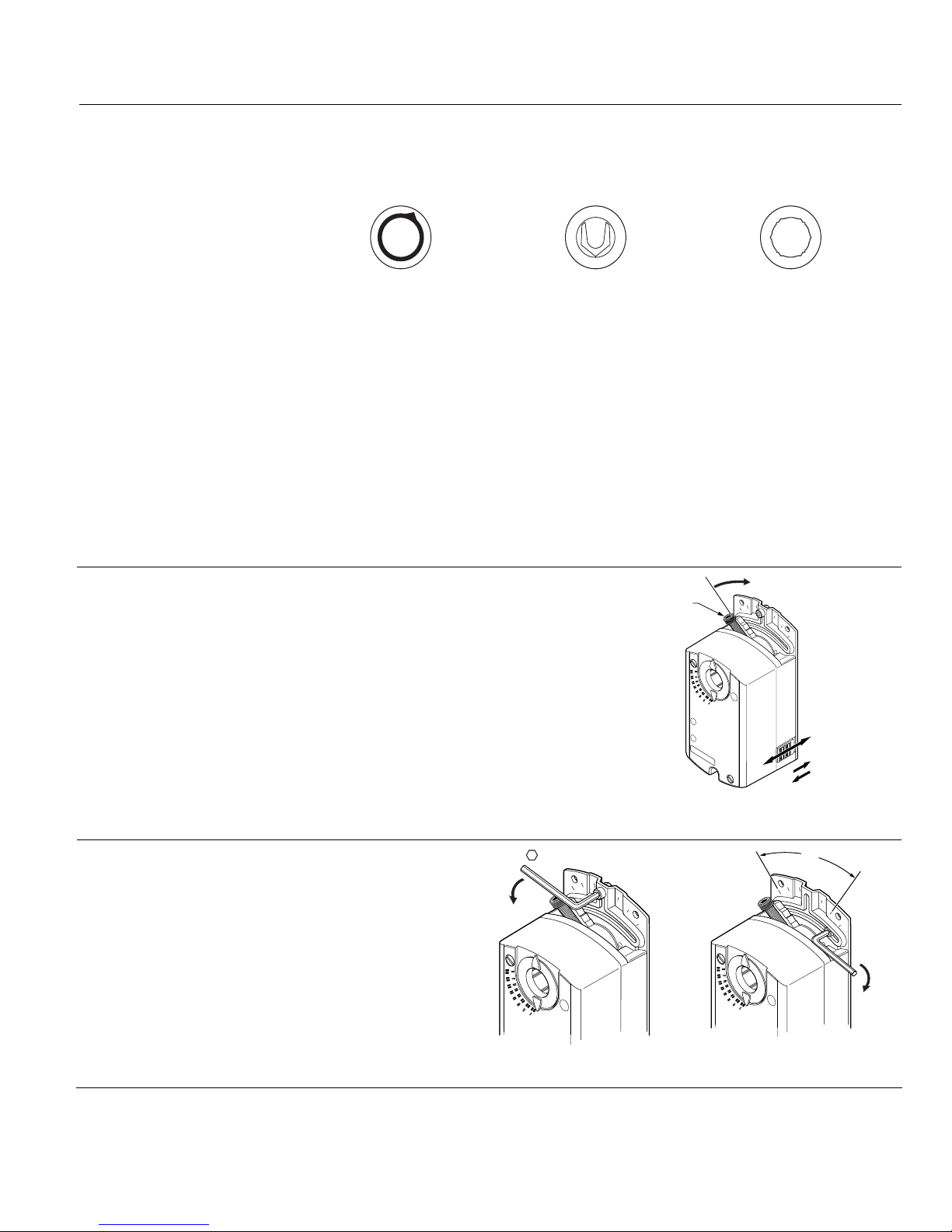
You must place the actuator on the damper shaft so that the front of the actuator is
accessible. The label is on the front side.
The minimum damper drive shaft length is 3/4-inch (20 mm).
Manual override
EA1002R1
1/2 Ø inch Guide
Factory Installed
Use shaft insert supplied
3/8 Ø inch
for any 3/8-in (8 - 10 mm)
diameter shaft
NOTE: For all damper shafts with the exception of the 1/2-inch round shaft:
Remove 1/2 Ø inch guide before installation.
Figure 14. Damper Shaft Sizes.
A mounting bracket is included with the actuator.
Observe the service envelope around the actuator as shown in Figure 25.
Detailed mounting instructions are included with each actuator.
To move the damper blades and lock the
position with no power present:
ADJUSTMENT
LEVER
2
1. Slide the red manual override knob
toward the back of the actuator.
2. Make adjustments to the damper
position.
90
45
90
3. Slide the red manual override knob
toward the front of the actuator.
PL0013R2
AUTO
Once power is restored, the actuator returns
to automated control
.
Figure 15. Manual Override.
5/8 Ø inch
MANUAL
1
3
Mechanical range
adjustment
1. Loosen the stop set
screw.
2. Move the screw along
the track to the desired
position, and fasten it in
place.
Siemens Building Technologies, Inc. Page 7
4 mm
1
90
45
90
EA0535R2
Figure 16. Moving the Mechanical Range Stop.
90¡
45¡
90¡
EA0536R2
<
90¡
2
Page 8
Technical Instructions OpenAir Non-Spring Return Rotary Electric Damper Actuator
Document No. 155-188P25
December 26, 2007
24 Vac Floating Control
Wiring
All wiring must conform to NEC and local codes and regulations.
Use earth ground isolating step-down Class 2 transformers. Do not use autotransformers.
The sum of the VA ratings of all actuators and all other components powered by one
transformer must not exceed the rating of the transformer. It is recommended that one
transformer power no more than ten actuators.
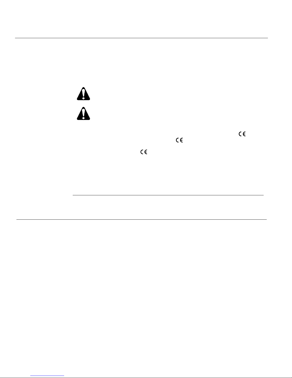
CAUTION:
Do not wire different types of actuators (such as GBBx or GIBx) in parallel with
the GDE13x or the GLB13x models.
WARNINGS:
All six outputs of the dual auxiliary switch (A and B) must only be connected to:
• Class 2 voltage (UL/CSA).
• Separated Extra-Low Voltage (SELV) or Protective Extra Low Voltage
(PELV) (according to HD384-4-41) for installations requiring
conformance. You must use a
Installations requiring
• All wiring for CE certified actuators must be "Separated Extra Low
Voltage" (SELV) or "Protective Extra Low Voltage" (PELV) per
HD384-4-41.
• Use safety-isolating transformers (Class III transformer) per EN61558.
They must be rated for 100% duty cycle.
• Over current protection for supply lines is maximum 10A.
Direction of Damper
Rotation
If the damper blades turn counterclockwise to open (CCW), reverse the 6 (violet) and
7 (orange) wires at the controller.
certified plenum rated actuator.
Conformance:
Page 8 Siemens Building Technologies, Inc.
Page 9
OpenAir Non-Spring Return Rotary Electric Damper Actuator Technical Instructions
24 Vac Floating Control Document No. 155-188P25
December 26, 2007
Wiring , Continued
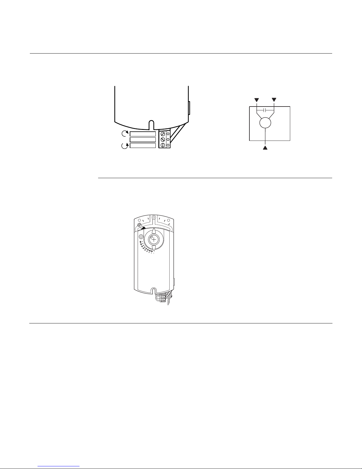
Terminal Strip
GDE161.1T
NOTE: Maximum wire size for the GDE131.1T 14 AWG.
GDE131.1T
CW
Supply 24Vac
EA1094R1
CCW
Figure 17. GDE131.1T Terminal
Strip.
Figure 18. GDE131.1T Wiring Diagram.
CW
EA1091R1
6
M
Supply
CCW
7
1
Strain Relief
Securing the wires/cabling will prevent
breakage and ensure strong signals to the
GDE131.1T model. The following is
recommended:
1. The open bracket to the right of the
90
5
4
90
actuator terminal strip is the strain
relief for the customer provided control
wires.
2. Secure the wires to the actuator
bracket with a cable tie as shown in
Figure 19.
EA1097R1
Figure 19.
Siemens Building Technologies, Inc. Page 9
Page 10
Technical Instructions OpenAir Non-Spring Return Rotary Electric Damper Actuator
Document No. 155-188P25
December 26, 2007
24 Vac Floating Control
Wiring, Continued
Post Header AMP
GDE131.1N
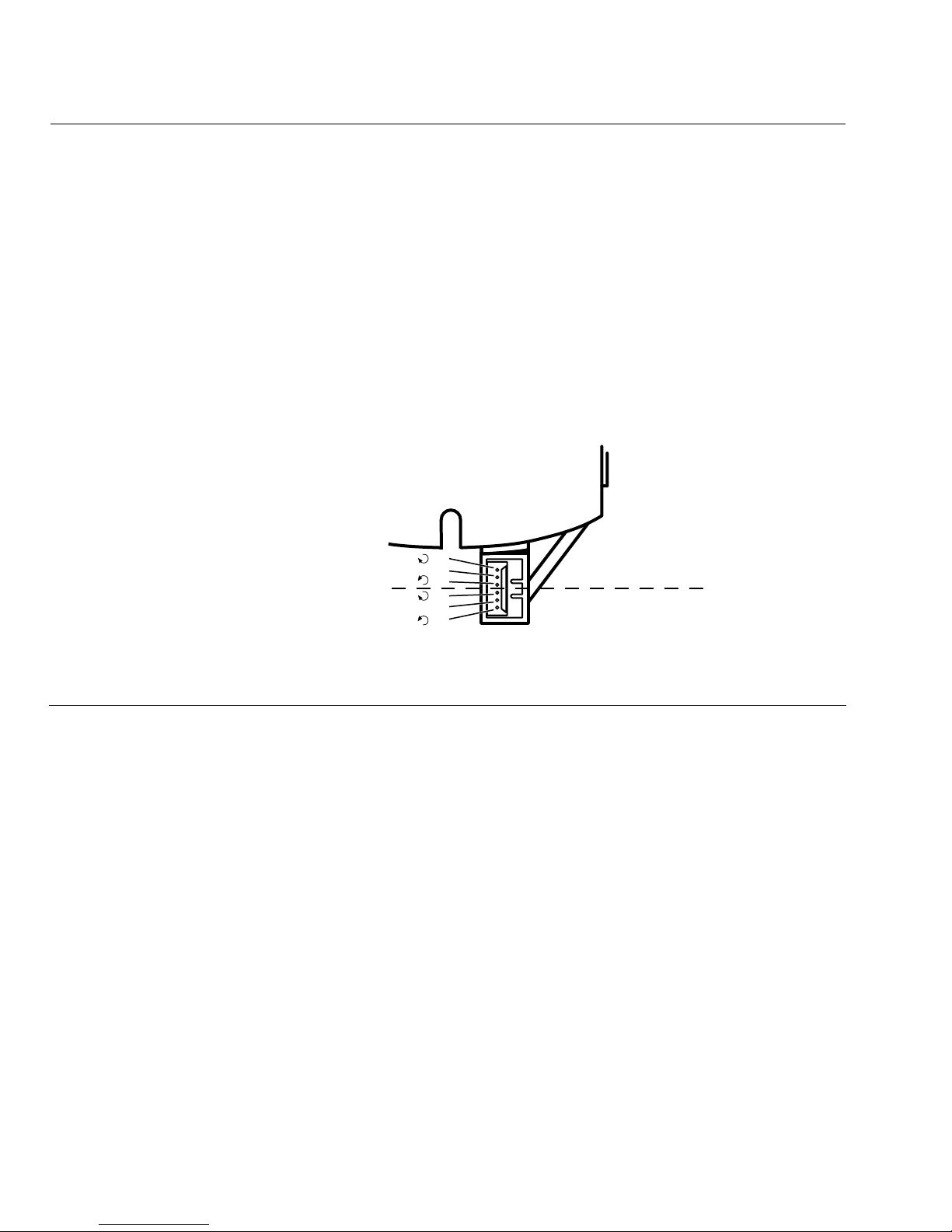
The GDE131.1N has two sets of identical contacts as shown in Figure 20.
• All wiring must conform to NEC and local codes and regulations.
• Use earth ground isolating step-down Class 2 transformers. Do not use
autotransformers.
• Determine the supply transformer rating by summing the total VA of all
actuators used. It is recommended that one transformer power no more than 12
actuators.
Direction of Damper Rotation
To change the direction of rotation of the GDE131.1N, switch the Y1 and Y2 wires at
the controller.
NOTE: This rotation will affect all actuators in the daisy chain configuration.
GDE131.1N
Y1
NOTE:
You must select
either the top 3
contacts or the
bottom 3 contacts.
EA1240R1
Y2
Y1
Y2
G
G
Input (Output)
Output (Input)
Figure 20. GDE131.1N Post Header AMP.
Page 10 Siemens Building Technologies, Inc.
Page 11
OpenAir Non-Spring Return Rotary Electric Damper Actuator Technical Instructions
24 Vac Floating Control Document No. 155-188P25
December 26, 2007
Wiring, Continued
Post Header AMP, Continued
GDE131.1N
Daisy Chain
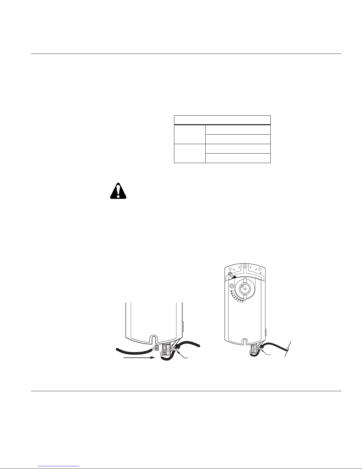
The input cable (purchased separately) brings power and a control signal to the first
actuator in a daisy chain configuration.
Table 3.
Floating Control Input Cables
985-131
3 ft
12 pk
985-132
3 ft Siemens TEC
12 pk
CAUTIONS:
Insert the plug into the Post Header AMP from the left to prevent
damage to the cable wires. See Figure 21.
1. The open bracket (See Figure 21), to the right of the
actuator, is used for strain relief of the customer purchased
daisy chain cable (See Required Tools).
2. Secure the cable to the actuator bracket with a cable tie as
shown in Figure 22.
NOTE:
You must select either
the top 3 contacts or
the bottom 3 contacts.
90
5
4
90
Input cable
from controller
sold separately
EA1247R1
Cable Tie
Figure 21.
Always Install the Cable Plug from
Cable
EA1244R1
Tie
Figure 22. Input Cable Installed in Bottom
Three Contacts.
the Left.
Siemens Building Technologies, Inc. Page 11
Page 12
Technical Instructions OpenAir Non-Spring Return Rotary Electric Damper Actuator
Document No. 155-188P25
24 Vac Floating Control
December 26, 2007
Wiring, Continued
Table 4.
GDE131.1N
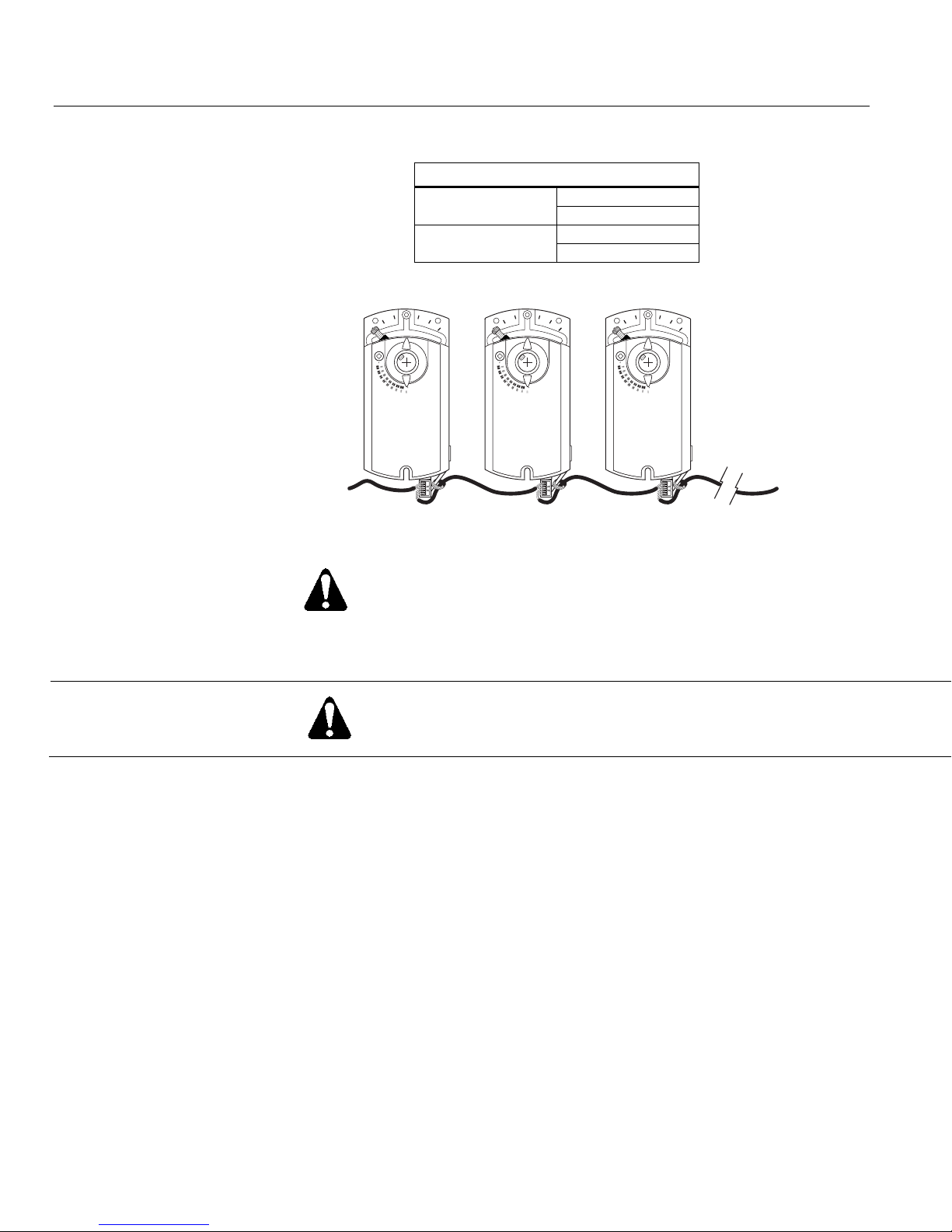
Daisy Chain
Daisy Chain Cable
985-134
985-135
12 ft
12 pk
25 ft
12 pk
90
5
4
90
Input cable
from controller
sold separately
EA1238R1
90
5
4
90
90
5
4
90
Figure 23.
WARNING:
Do not daisy chain more than 12 actuators together at any time.
Troubleshooting
WARNING:
Do not open the actuator. If the actuator is inoperative, replace the unit.
Page 12 Siemens Building Technologies, Inc.
Page 13
OpenAir Non-Spring Return Rotary Electric Damper Actuator Technical Instructions
24 Vac Floating Control Document No. 155-188P25
December 26, 2007
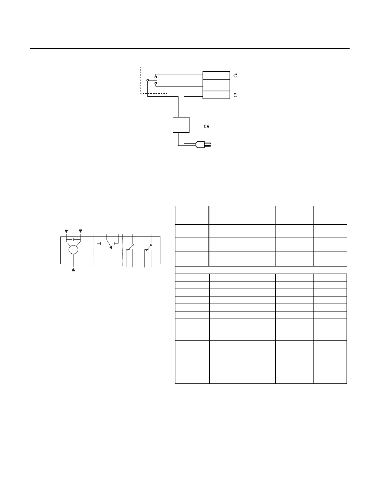
Wiring Designations
24 Vac power supply
Floating Control 24 Vac
7
6
P1
Each wire has the standard symbol printed on it.
CW
SUPPLY
CCW
EARTH GROUND
ISOLATING CLASS 2
TRANSFORMER FOR
24 Vac POWER
: SAFETY ISOLATING
TRANSFORMER
PER EN 60742
120 Vac
EA1095R1
NEUT
24
Vac
Figure 24. Floating Control.
Table 5. Floating Control 24 Vac.
Standard
Function Terminal
Symbol
P3P2 S1
S4
1 Supply (SP) G Red
Color
Designation
EA0282R1
A
M
1000
B
6 Control signal
clockwise
7 Control signal
Y1 Violet
Y2 Orange
counterclockwise
1
S2 S3 S5 S6
S1 Switch A - Common Q11 Black
Factory-Installed Options
S2 Switch A - NC Q12 Black
S3 Switch A - NO Q14 Black
S4 Switch B - Common Q21 Black
S5 Switch B - NC Q22 Black
S6 Switch B - NO Q24 Black
P1 Feedback
a Black
Potentiometer
0 to 100% P1 - P2
P2 Feedback
b Black
Potentiometer
Common
P3 Feedback
c Black
Potentiometer
100 to 0% P3 - P2
Siemens Building Technologies, Inc. Page 13
Page 14

Technical Instructions OpenAir Non-Spring Return Rotary Electric Damper Actuator
Document No. 155-188P25
December 26, 2007
24 Vac Floating Control
Start-Up/
Commissioning
1. Check that the wires are connected correctly.
2. Connect wires 1 (red) and 6 (violet) to a Digital Multimeter (DMM) with the dial set at Vac.
Apply a control signal (24 Vac) to wires 1 and 6 to verify that the operating voltage is within
range.
3. Connect wires 1 (red) and 7 (orange) to a DMM with the dial set at Vac. Apply a control
signal (24 Vac) to wires 1 and 7 to verify that the operating voltage is within range.
Check Operation:
1. Connect wire 1 (red) to the actuator.
2. Apply a control signal (24 Vac) to wires 1 (red) and 6 (violet).
3. Allow the actuator shaft coupling to rotate from 0° to 90°.
4. Stop applying a control signal to wires 1 (red) and 6 (violet).
5. Apply a control signal (24 Vac) to wires 1 (red) and 7 (orange).
6. Allow the actuator shaft coupling to rotate from 90° to 0°.
Check Feedback:
1. Set the DMM dial to ohms.
2. Connect wires P1 and P2 to the DMM. The DMM should indicate a resistive value.
3. Apply a control signal (24 Vac) to wires 1 (red) and 6 (violet).
The reading of the DMM should increase.
4. Connect wires P2 and P3 to the DMM. The DMM should indicate a resistive value.
5. Apply a control signal (24 Vac) to wires 1 (red) and 7 (orange).
The reading of the DMM should increase.
Check the Auxiliary Switch A:
1. Set the DMM dial to ohms (resistance) or continuity check.
2. Connect wires S1 and S3 to the DMM.
The DMM should indicate an open circuit or no resistance.
3. Apply a control signal (24 Vac) to wires 1 (red) and 6 (violet).
The DMM should indicate contact closure as the actuator shaft coupling reaches the setting of
switch A.
4. Stop applying a control signal to wires 1 (red) and 6 (violet).
5. Connect wires S1 and S2 to the DMM.
The DMM should indicate an open circuit or no resistance.
6. Apply a control signal (24 Vac) to wires 1 (red) and 7 (orange). The DMM should indicate contact
closure as the actuator shaft coupling reaches the setting of switch A.
Page 14 Siemens Building Technologies, Inc.
Check the Auxiliary Switch B:
1. Set the DMM dial to ohms (resistance) or continuity check.
2. Connect wires S4 and S6 to the DMM.
The DMM should indicate an open circuit or no resistance.
3. Apply a control signal (24 Vac) to wires 1 (red) and 6 (violet). The DMM shoul d indicate contact
closure as the actuator shaft coupling reaches the setting of switch B.
4. Stop applying a control signal to wires 1 (red) and 6 (violet).
5. Connect wires S4 and S5 to the DMM. The DMM should indicate an open circuit or no resistance.
6. Apply a control signal (24 Vac) to wires 1 (red) and 7 (orange). The DMM should indicate contact
closure as the actuator shaft coupling reaches the setting of switch B.
Page 15
OpenAir Non-Spring Return Rotary Electric Damper Actuator Technical Instructions
24 Vac Floating Control Document No. 155-188P25
December 26, 2007
Dimensions
7/16
(11)
min. 1/4 inch
15/16
(94)
min. 4 inch
100 mm
6 mm
2-3/8
(60)
1/32
(0.8)
min. 8 inch
200 mm
min. 2-3/8 inch
60 mm
5-7/16
(137)
min. 3/8 inch
10 mm
3-7/16
(87)
90
5/32
(4)
min. 1 inch
25 mm
1/2
(12)
EA0531R2
6-5/8
(168)
25/32
(20)
7-1/16
(180)
13/16
(21)
2-3/4
EA0530R3
(70)
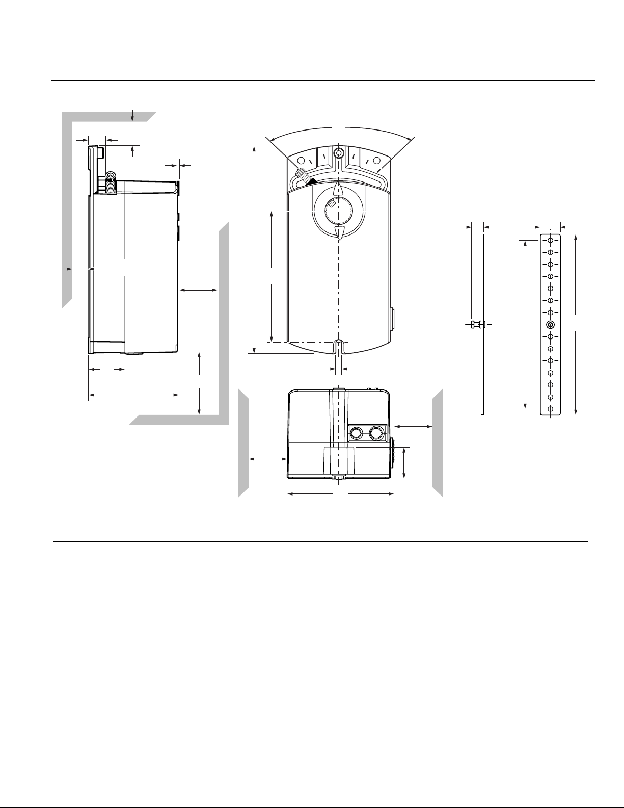
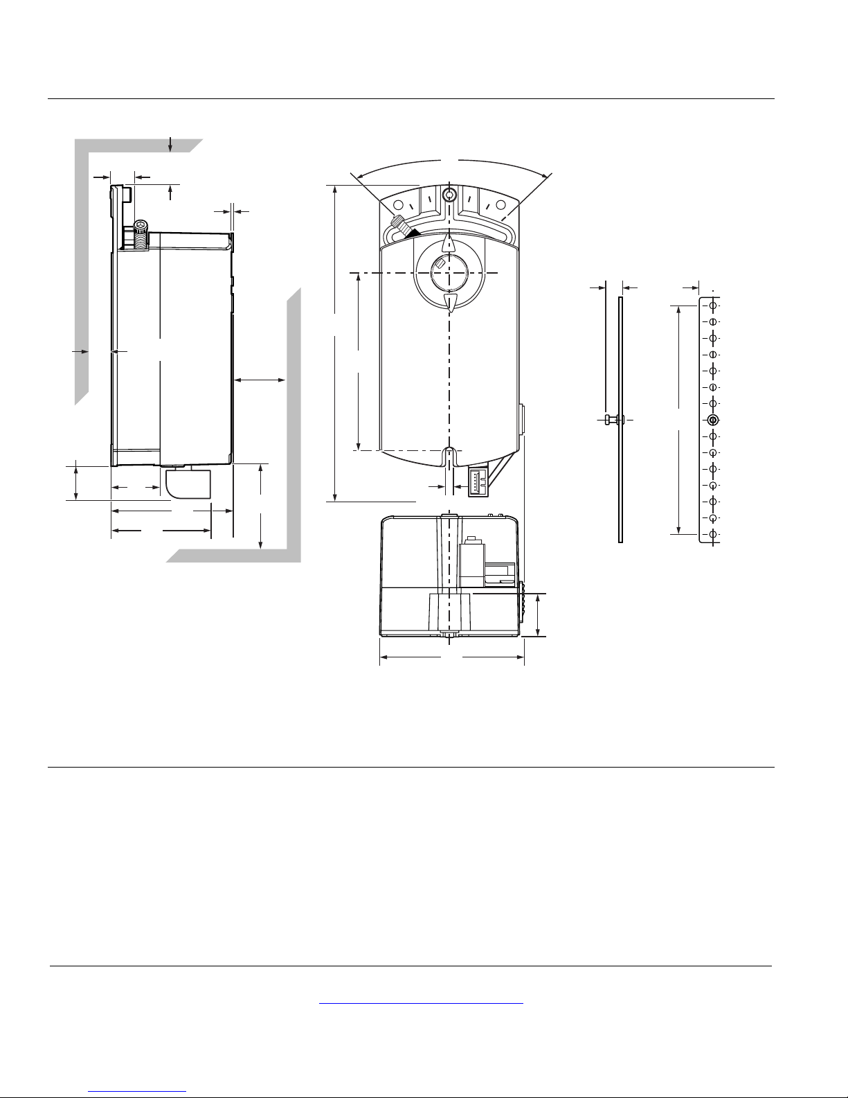
Figure 25. GDE/GLB Actuator and Mounting Bracket Dimensions in Inches (Millimeters).
Siemens Building Technologies, Inc. Page 15
Page 16
Technical Instructions OpenAir Non-Spring Return Rotary Electric Damper Actuator
6-5/8
(168)
EA0531R2
1/2
(12)
25/32
(20)
Document No. 155-188P25
24 Vac Floating Control
December 26, 2007
Dimensions, Continued
.8
(19,3)
.46
(12)
.96
(24)
min. .25
(6)
1.8
(44,9)
min. 4
(100)
2.4
2.4
(61)
(61)
.04
(1)
min. 8
(200)
min. 2.38
(60)
6.2
(156,3)
3.4
(87)
.16
(4,15)
90
.84
(21,4)
2.8
EA1242R1
(70,7)
Figure 26. GDE131.1T, GDE131.1N, and Mounting Bracket Dimensions in Inches (Millimeters).
Information in this publication is based on current specifications. The company reserves the right to make changes in specifications and models as
design improvements are introduced. OpenAir is a trademark of Siemens Building Technologies, Inc. Product or company names mentioned herein
may be the trademarks of their respective owners. © 2007 Siemens Building Technologies, Inc.
Siemens Building Technologies, Inc.
1000 Deerfield Parkway
Buffalo Grove, IL 60089-4513
U.S.A.
Your feedback is important to us. If you have
comments about this document, please send them
to [email protected]
Document No. 155-188P25
Country of Origin: US
Page 16
 Loading...