

Siemens NK8000 Series, NK8222, NK8225, NK8223, NK8232 Installation, Configuration & Operation
...
A6V10062437_a_en
Building Technologies
30.01.2019
CPS Fire Safety
NK8000 MP4.81-02
NK8222, NK8223, NK8225
NK8231, NK8232, NK8235
Installation
Configuration
Commissioning


3
Building Technologies A6V10062437_a_en
CPS Fire Safety
30.01.2019
Table of contents
About this document ......................................................................................................... 5
Security disclaimer ............................................................................................................ 8
Safety regulations .............................................................................................................. 9
Country-specific standards .................................................................................................. 9
Assembly and installation .................................................................................................... 9
Commissioning and testing.................................................................................................. 9
Disposal and recycling ....................................................................................................... 10
Modifications to the system design and the products ........................................................ 10
Data privacy and protection ............................................................................................... 10
1 Introduction....................................................................................................... 11
1.1 Interactions ......................................................................................................... 12
1.2 What's new ......................................................................................................... 13
1.3 System dimensions and compatibility list ........................................................... 13
2 System limits .................................................................................................... 14
2.1 NS8210 driver system limits ............................................................................... 14
2.2 NS8011 driver system limits ............................................................................... 14
2.3 NK822x system limits ......................................................................................... 15
2.4 NK823x system limits ......................................................................................... 16
3 Structure and functions ................................................................................... 18
3.1 NK822x hardware ............................................................................................... 18
3.1.1 Front panel .......................................................................................... 18
3.1.2 Internal DIP switches .......................................................................... 19
3.1.3 Internal jumpers .................................................................................. 19
3.1.4 Serial interfaces .................................................................................. 20
3.1.5 LON interface ...................................................................................... 21
3.1.6 Ethernet interface ................................................................................ 22
3.1.7 I2C interface: I/O and power supervision ............................................ 23
3.2 NK823x hardware ............................................................................................... 24
3.2.1 Front panel .......................................................................................... 24
3.2.2 Internal DIP switches .......................................................................... 25
3.2.3 Internal jumpers .................................................................................. 26
3.2.4 Serial interfaces .................................................................................. 27
3.2.5 LON interface ...................................................................................... 27
3.2.6 Onboard I/O ........................................................................................ 28
3.2.7 I2C interface: I/O and power supervision ............................................ 28
3.2.8 Ethernet interfaces .............................................................................. 30
3.2.9 USB interface ...................................................................................... 30
3.2.10 SD card ............................................................................................... 31
4 NK8000 Security ............................................................................................... 32
5 Hardware installation ....................................................................................... 33
5.1 NE8001 housing solution for NK823x ................................................................ 33

4
Building Technologies A6V10062437_a_en
CPS Fire Safety
30.01.2019
5.1.1 NE8001 hardware requirements ......................................................... 33
5.1.2 NE8001 hardware installation ............................................................. 34
5.2 NK822x hardware installation ............................................................................. 36
5.3 NK823x hardware installation ............................................................................. 42
6 Software installation ........................................................................................ 48
6.1 Installation checklist ............................................................................................ 48
6.2 Composer tool .................................................................................................... 48
6.3 Launching Composer ......................................................................................... 49
6.4 NW8202 IP configuration download tool ............................................................ 50
6.4.1 NW8202 hardware requirements ........................................................ 50
6.4.2 NW8202 software requirements ......................................................... 50
6.4.3 NW8202 installation ............................................................................ 51
6.5 NW8204 diagnostic tool...................................................................................... 51
6.5.1 NW8204 hardware requirements ........................................................ 51
6.5.2 NW8204 software requirements ......................................................... 51
6.5.3 NW8204 installation ............................................................................ 51
6.6 Secure communication for web services ............................................................ 53
7 Configuration .................................................................................................... 54
7.1 Configuration checklist ....................................................................................... 54
7.2 Configuring IP settings via NW8202 ................................................................... 55
7.3 Configuring the relay output ............................................................................... 57
8 Testing the configuration ................................................................................ 59
8.1 Checking NK82xx connection(s) ........................................................................ 59
9 Maintenance and diagnostics ......................................................................... 60
9.1 Kernel update ..................................................................................................... 60
9.2 The NK8000 maintenance and diagnostic tools ................................................. 61
9.3 The NW8204 diagnostic tool .............................................................................. 62
9.3.1 Launching NW8204 from DMS host ................................................... 63
9.3.2 File commands .................................................................................... 65
9.3.3 Diagnostic functions ............................................................................ 66
9.3.4 Uploading diagnostic files ................................................................... 68
9.3.5 Using log files ...................................................................................... 71
9.4 The NK8000 Web Server tool ............................................................................ 74
9.4.1 Working with the NK8000 Web Server ............................................... 74
9.5 Correcting communication failures ..................................................................... 80
9.5.1 NK82xx generated a fault ................................................................... 80
9.5.2 Control unit generated a fault .............................................................. 81
9.5.3 Control unit not responding ................................................................. 81
9.5.4 CS6 Guarto generated a fault ............................................................. 81
9.5.5 No fault generated by network failure - MP3.15 and higher ............... 82
10 Secure operation requirements ...................................................................... 83

About this document
5
Building Technologies A6V10062437_a_en
CPS Fire Safety
30.01.2019
About this document
Purpose
This document is a guide to the planning, installation and configuration of the
NK8000 safety and security network. It includes an overview of the system,
hardware requirements and limitations, and detailed installation and configuration
instructions. Hardware components detailed in this manual include the NK822x
(NK8222, NK8223, NK8225) and NK823x (NK8231, NK8232, NK8235) Ethernet
Ports.
This guide is to be used in conjunction with the product-specific
Danger
Management System Installation, Configuration, and Commissioning guide
(MM8000 / MK8000 / MT8001)
, and the DMS8000 Connectivity Guides.
Scope
This document applies to NK8000 MP4.81-02 service release.
Target audience
This documentation is intended for the following users:
⚫ Project Managers
⚫ Project Engineers
⚫ Commissioning Personnel
It is assumed that individuals performing the operations described in this manual
have prior expertise and training in the field of safety and security, at least a
moderate level of familiarity with the Siemens Building Technologies product line,
and experience with the installation, configuration, and commissioning of security
management systems.
Documentation resource information
The
DMS8000 Documentation Resource Information and Glossary Guide
assembles important information regarding documentation resources. This
document contains the following:
⚫ Comprehensive definitions of the target audiences for Siemens FS DMS
documents
⚫ Training program information including the Siemens intranet link
⚫ A complete list of all available DMS8000 documents
⚫ Instructions for how to obtain a document via the Siemens intranet using the
Siemens Asset Portal
⚫ A map of relevant documents for each target audience group
⚫ Customer Support links & resources
⚫ A glossary containing definitions of all terms and acronyms used in DMS8000
documentation
To access the
DMS8000 Documentation Resource Information and Glossary
Guide
(document no. A6V10089056), go to the link and follow the document
search instructions below:
https://step.bt.siemens.com/portal/StandardAssetPortal
1. In the Simple Search column on the left, set:
– Search Text: Enter the document number to search for (for example
A6V10089056
) or type part of the document name.
– Asset Type: All
2. Click Search to start.
About this document
6
Building Technologies A6V10062437_a_en
CPS Fire Safety
30.01.2019
3. In the resulting area on the right, click on Contents link to show the list of
search results.
4. In the list, select one or more documents and click the Download Assets icon.
5. After the download preparation completes (Background Process …), click
Download and follow the instructions of your browser.
For more information such as Siemens news and announcements, visit the STEP
Web portal at:
https://workspace.sbt.siemens.com/content/00001123/default.aspx
Note: Before beginning work on the system you must have read and understood
the Safety Regulations [➙ 9] section in this manual.
Liability disclaimer for damage or injuries
Before products are delivered, they are tested to ensure they function correctly
when used properly. Siemens disclaims all liability for damage or injuries caused
by the incorrect application of the instructions, or the disregard of danger
advisories. This disclaimer applies in particular to personal injuries or damage
caused by:
⚫ Improper and/or incorrect use.
⚫ Disregard of safety instructions in the documentation or on the product.
⚫ Poor maintenance or a lack of maintenance.
We have checked the contents of this manual for agreement with the hardware and
software described. Since deviations cannot be precluded entirely, we cannot
guarantee full agreement. However, the data in this manual are reviewed regularly
and any necessary corrections are included in subsequent editions. Suggestions
for improvement are welcome.
Copyrights and registered trademarks
Brand or product names mentioned in this document may be names protected by
copyright law or registered trademarks of other companies. These are mentioned
only for identification purposes and have no recommendatory character in regard to
the product or manufacturer, unless otherwise stated.
Documentation Conventions
The following table lists conventions to help you use this document in a quick and
efficient manner.
Convention
Examples
Numbered Lists (1, 2, 3…) indicate a
procedure with sequential steps.
1. Turn OFF power to the field panel.
2. Disconnect the power cord.
3. Open the cabinet.
One-step procedures are indicated by a
bullet point.
⚫ Expand the Event List.
Conditions that you must complete or must
be met before beginning a procedure are
designated with a ⊳.
Results, after completing a step or at the
end of the entire procedure, are designated
with a ⇨.
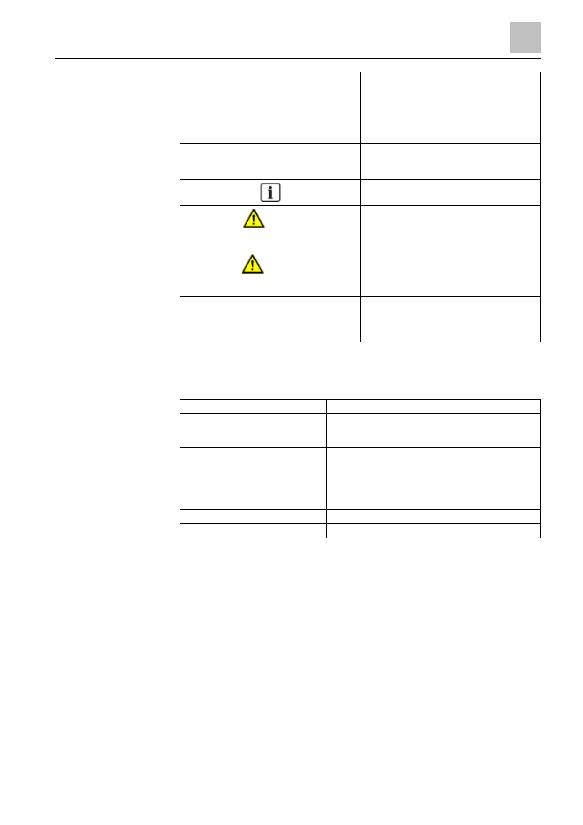
⊳ The report you want to print is open.
1. Click the Print icon .
⇨ The Print dialog box appears.
2. Select the printer and click Print.
⇨ The print confirmation appears.
Bold font in a procedure indicates something
you should select or type.
Type F for Field panels.
Click OK to save changes and close the
dialog box.
About this document
7
Building Technologies A6V10062437_a_en
CPS Fire Safety
30.01.2019
Menu paths are indicated in bold.
Select File > Text, Copy > Group, which
means from the File menu, then select Text,
Copy and finally Group.
Error and system messages are displayed in
Courier New font.
The message Definition
successfully renamed displays in the
status bar.
Italics
are used to emphasize a term.
The Open Processor continuously executes
a user-defined set of instructions called the
control program
.
This symbol signifies a Note. Notes provide
additional information or helpful hints.
Caution
This is a Caution message and indicates
that minor or moderate injury or property
damage may occur if a procedure is not
followed.
Warning
This is a Warning message and indicates
that a serious injury or a severe equipment
and property damage may occur if a
procedure is not followed.
Cross references to other information in
printed material are indicated with an arrow
and the page number, enclosed in brackets:
[→92]
For more information on creating flowcharts,
see Flowcharts [→92].
Modification index
Note: For versions more than four years old, please visit the Siemens Asset Portal.
Version
Date
Notes
A6V10062437_a_en
01.2019
NK8000 MP4.81-02 service release.
For details regarding updates/modifications, see What's
new [➙ 13].
A6V10062437_b_en
09.2017
NK8000 MP4.81-01 service release.
For details regarding updates/modifications, see What's
new [➙ 13].
A6V10062437_a_en
09.2016
NK8000 MP4.81.
A6V10062437_a_en
09.2015
NK8000 MP4.80.
A6V10062437_a_en
09.2014
NK8000 MP4.70.
A6V10062437_a_en
06.2013
NK8000 MP4.60.

Security disclaimer
8
Building Technologies A6V10062437_a_en
CPS Fire Safety
30.01.2019
Security disclaimer
Products, solutions and services from Siemens include security functions to ensure
the secure operation of building automation and control, fire safety, security
management, and physical security systems. The security functions on these
products, solutions and services are important components of a comprehensive
security concept.
Drafting, implementing and managing a comprehensive and up-to-date security
concept, customized to individual needs, is nevertheless necessary, and may result
in additional plant- or site-specific preventive measures to ensure secure operation
of your site regarding building automation and control, fire safety, security
management, and physical security. These measures may include, for example,
separating networks, physically protecting system components, user training, multilevel defensive measures, etc. For additional information on security as part of
building technology and our product, solution and service offerings, please contact
your Siemens sales representative or project department. We strongly recommend
to always comply with our security advisories on the latest security threats, patches
and other related measures.
http://www.siemens.com/cert/en/cert-security-advisories.htm

Safety regulations
Country-specific standards
9
Building Technologies A6V10062437_a_en
CPS Fire Safety
30.01.2019
Safety regulations
This section describes the danger levels and the relevant safety regulations
applicable to the use of the products described in this manual. Please read the
following work instructions as well as the preceding section
About this document
thoroughly before beginning any work.
Danger potential to individuals
NK8000 units are powered with low voltage DC. While there are no specific safety
regulations that apply to these devices, modifications made to safety/security
systems in general may present a risk to the safety of the individual performing
those modifications, as well as to the equipment itself.
If used, the NE8001 cabinet is powered with AC voltage and the required power
cable should be installed following scrupulously the instructions given in this
manual.
Country-specific standards
Siemens Building Technologies products are developed and produced in
compliance with the relevant international and European safety standards. This
document provides warnings and recommendations specific to NK8000 products.
Any additional country-specific or local safety standards and/or regulations that
apply concerning project planning, installation, operation, and device disposal must
also be taken into account.
Note: As for any electrical equipment, proper grounding is critical to the safe
operation as it provides a protection against electrical shocks. Before starting any
activity, be sure that the electrical installation complies with relevant regulations
and conforms to local safety standards.
Assembly and installation
The NK8000 units and NE8001 cabinets should always be installed in a clean and
stable environment; see the specific requirements given in the Technical Data
section of the specific datasheets.
In particular, keep units and cabinets away from the following:
⚫ High levels of dust
⚫ High temperature and humidity
⚫ Locations where it might became wet
⚫ Vibration and impact
Also, abide by the safety regulations of the connected devices.
Commissioning and testing
⚫ Activate security-, fire- and third party systems or devices only in the presence
of the person responsible.
⚫ Inform people before the testing of alarm devices — consider the possibility of
panic reactions.
⚫ Inform the alarm and fault receiving stations connected to the system before
carrying out tests.
Safety regulations
Disposal and recycling
10
Building Technologies A6V10062437_a_en
CPS Fire Safety
30.01.2019
Disposal and recycling
These devices include electrical and electronic components and must
not be disposed of as domestic waste.
Current local legislation must be observed.
The NK8000 units have been manufactured as much as possible from materials
that can be recycled or disposed of in a manner that is not environmentally
damaging. However, they contain parts (batteries) that require disposal in a
controlled waste stream according to local environmental standards and/or
regulations.
Modifications to the system design and the products
Note: Modifications to a system or to individual products may cause faults or
malfunctioning.
Please request written approval from Siemens Building Technologies and from any
relevant authorities concerning intended system modifications and system
extensions.
Data privacy and protection
Make sure that the configuration of the system complies with local data privacy and
protection regulations.
Introduction
1
Interactions
11
Building Technologies A6V10062437_a_en
CPS Fire Safety
30.01.2019
1 Introduction
The NK8000 family provides LAN/WAN adapter products for a safety and security
network:
⚫ NK822x series (no longer available, end of service: 31 December 2015)
⚫ NK823x Ethernet Ports series (NK8231, NK8232, NK8235)
⚫ NK8237 Modbus Gateway
⚫ NK8237 IEC 60870-5-104 Gateway
The
NK822x series
includes:
⚫ NK8222 Ethernet port: LAN/WAN (CMSDL/IP, CEI-79) and Dial-up (CEI-79)
communication unit supporting one subsystem connection over RS232 line or
CerCom/LON bus, and locally connected DF8000 I/O units. It can provide local
interactions between points in the connected subsystem and I/O.
⚫ NK8223 Ethernet port: LAN/WAN (CMSDL/IP, CEI-79) and Dial-up (CEI-79)
communication unit supporting up to 4 RS232 lines, one CerCom/LON bus,
and locally connected DF8000 I/O units. It can provide local interactions
between points in the connected subsystems and I/O.
⚫ NK8225 Ethernet port: LAN/WAN (BACnet/IP, CMSDL/IP, CEI-79) and Dial-up
(CEI-79) communication unit supporting up to 4 RS232 lines, one
CerCom/LON bus, and locally connected DF8000 I/O units. It can provide local
interactions between points in the connected subsystems and I/O, as well as
network-wide over other NK8225s or NK823xs.
The
NK823x series
includes:
⚫ NK8231 CEI Interface for a single subsystem: LAN/WAN/Dial-up (CEI-79)
communication unit supporting one subsystem connection over RS232 line as
well as onboard I/O and locally connected DF8000 I/O modules.
Note: NK8231 is intended for use with MM2000 Management Stations, which are
only available in the Italian market.
⚫ NK8232 Ethernet port (single): LAN/WAN (BACnet/IP, CMSDL/IP, CEI-79) and
Dial-up (CEI-79) communication unit supporting one subsystem connection
over RS232 line as well as onboard I/O and locally connected DF8000 I/O
modules. It can provide local and interactions between points in the connected
subsystems and I/O, as well as network-wide interactions over other NK8225s
or NK823xs. In addition, it can act as Modbus Gateway and IEC 60870-5-104
Gateway for FS20/STT20/FS720.
⚫ NK8235 Ethernet port: LAN/WAN (BACnet/IP, CMSDL/IP, CEI-79) and Dial-up
(CEI-79) communication unit supporting up to 4 RS232 lines as well as
onboard I/O and locally connected DF8000 I/O modules. It can provide local
interactions between points in the connected subsystems and I/O, as well as
network-wide interactions over other NK8225s or NK823xs. In addition, it can
act as Modbus Gateway and IEC 60870-5-104 Gateway for
FS20/STT20/FS720.
Note: The Modbus host interface is discussed in the NK8237 Modbus Gateway
ICC manual, (document A6V10316241). This document should be used for
configuring the Modbus host also on NK8232 and NK8235.
Note: The IEC 60870-5-104 host interface is discussed in the NK8237 IEC 608705-104 Gateway ICC manual, (document A6V10854379). This document should
be used for configuring the IEC 60870-5-104 host also on NK8232 and NK8235.
1
Introduction
Interactions
12
Building Technologies A6V10062437_a_en
CPS Fire Safety
30.01.2019
1.1 Interactions
The unit can be programmed to support interactions between the connected
subsystems: when a specified message is received from a source subsystem, one
or more commands are generated for a destination subsystem according to the
programmed interaction logic.
Interactions can be
local
or
network-wide
:
⚫ Local interactions only involve the subsystems connected to a single unit.
⚫ Network-wide interactions involve subsystems connected on different units,
which coordinate the interaction task over the network. Network-wide
interactions require units supporting the BACnet protocol.
Note: NK8000 units are not certified as part of an EN54-2 fire detection system.
Therefore, the interactions should only be used in applications where they are not
in conflict with EN54 standards or national guidelines or regulations (e.g., not for
common control of remote transmission devices).
Note: NK8231 and NK8237 do not support interactions.
Both local and network-wide interactions are supported for a restricted list of
subsystems:
⚫ FS20 Sinteso Fire control units (this subsystem is not supported by NK822x)
⚫ FS720 Cerberus PRO Fire control units (this subsystem is not supported by
NK822x), excluding FC721, which does not support BACnet connections to
management stations
⚫ STT20 Fire control unit (this subsystem is not supported by NK822x)
⚫ CS11 AlgoRex
®
Fire control unit
⚫ CS1115 Fire control unit
⚫ FC330A Fire control unit
⚫ FC700A Fire control unit
⚫ SIGMASYS/D100 Fire control unit
⚫ XLS FireFinder control unit
⚫ CS6 Guarto Intrusion control unit
⚫ Sintony SI410 Intrusion control unit
⚫ DF8000/CF9000 I/O modules
⚫ MK7022 Cerloop Interface
⚫ Philips Burle CCTV switcher
For details on interactions, see the
Network Connectivity Guide
(document
no.A6V10359485).
Introduction
1
What's new
13
Building Technologies A6V10062437_a_en
CPS Fire Safety
30.01.2019
1.2 What's new
Here is the list of modifications for new functions and software improvements.
NK8000 MP4.81-02 Service Release
Section
Modifications
6.4 NK823x Web Server
Removed support of NK823x Web Server
7.2 Configuring IP settings via the NK823x Web
Server
Removed support of NK823x Web Server
9.4 NK823x Web Server
Removed support of NK823x Web Server
NK8000 MP4.81-01 Service Release
Section
Modifications
SNMP monitoring
Removed SNMP support.
NK8000 MP4.81
Section
Modifications
Introduction [➙ 11]
Enhanced NK8000 family and new IEC 60870-5104 gateway.
Kernel Update [➙ 60]
In the About window, the NK8000 Kernel Update
utility displays the feature set that gets installed in
addition to the new Kernel version.
1.3 System dimensions and compatibility list
Please refer to
NK823x Datasheets
(NK8231 - A6V10238662, NK8232 A6V10238667, NK8235 - A6V10238669). Also, the latest information and
compatibility issues about the current software can be found in the
NK8000
Release Notes
(A6V10062453).
2
System limits
NS8210 driver system limits
14
Building Technologies A6V10062437_a_en
CPS Fire Safety
30.01.2019
2 System limits
The following describes the system limits for the NK82xx units and the
corresponding NS82xx drivers for DMS8000 (MM8000 and MK8000) systems. For
detailed information about supported subsystem software versions see the
NK8000
Release Notes
(document n.A6V10062453.)
2.1 NS8210 driver system limits
NS8210 Ethernet Port connections (CMSDL/IP and CEI 79-5)
Currently, there is a limit of 500 NK82xx units per NS8210.
Note: Please contact customer support for configurations above 100 NK82xx.
NS8210 Transport protocols
NS8210 supports the transport protocols CMSDL/IP or CEI 79-5 for communication
with the Ethernet Ports.
Note: The cryptography option is only supported with the CEI 79-5 protocol.
Multiple host configurations are only supported with the CMSDL/IP protocol.
2.2 NS8011 driver system limits
NS8011 Ethernet Port connections (BACnet/IP)
Currently, there is a limit of 64 BACnet/IP connections per Server/FEP Station.
NS8011 Transport protocols
NS8011 supports the BACnet/IP protocol for communication with the NK8225,
NK8232, and NK8235.
Note: Encryption is not supported.
Subsystems supported
Same as interactions, refer to the list [➙ 12].

System limits
2
NK822x system limits
15
Building Technologies A6V10062437_a_en
CPS Fire Safety
30.01.2019
2.3 NK822x system limits
Network capabilities (upstream towards management system host)
⚫ Ethernet IEEE 802.3, 10Base-T, half-duplex, no auto-sensing or auto-
negotiation
⚫ Single host transport protocols:
– CEI 79-5 type A and B (optional FEAL 64-bit encryption)
– CMSDL/IP
– BACnet/IP (NK8225 only)
⚫ Multiple hosts (up to four) transport protocols:
– CMSDL/IP
– BACnet/IP (NK8225 only)
⚫ DHCP is currently not supported. A static IP address is required.
Serial capabilities (downstream towards subsystems and upstream
towards local management system host)
NK8223/NK8225: The maximum number of serial lines is 4, allowing connection to
up to 4 local units (intrusion, access control, fire, gas detection, CCTV control
units). Two serial lines are available on the CPU module and two on an expansion
module. The serial lines can also be used for a local host or a dial-up host
connection.
NK8222: The maximum number of serial lines is 2 (on the CPU module). Only one
connection to a local unit (intrusion, access control, fire, gas detection, CCTV
control units) is allowed. The second line can be used for a local host or a dial-up
connection.
In all NK822x models, the first serial port can be configured as an RS232-interface
using connector COM1 or as an RS485-interface using connector CN4.
Interaction capabilities
NK822x provides programmable interaction programs, including single or multiple
triggers (incoming events) and single or multiple effects (outgoing control actions).
Interactions are possible between locally connected subsystems.
The NK8225 can provide network-wide interaction capabilities between other
BACnet NK82xx units.
⚫ Subsystems supported (see Interactions [➙ 12]).
⚫ Logical combinations: AND, OR, XOR, NOT
⚫ Delay of effects (wait): configurable 0…6500 sec.
⚫ Max. # of typical interactions (1-6 triggers, 1-4 effects): 500
⚫ Total # of field points used in triggers/effects: 5000
⚫ Max. # of field points/interactions that can be combined in a trigger expression:
255
Modules locally connected via I2C
⚫ Up to 16 digital inputs (2 DF8040 modules)
⚫ Up to 8 digital outputs (1 DF8020 module)
⚫ Power supply supervision (1 DF8090 module)
Further input/output modules can be connected over the serial lines.
2
System limits
NK823x system limits
16
Building Technologies A6V10062437_a_en
CPS Fire Safety
30.01.2019
2.4 NK823x system limits
Network capabilities (upstream towards management system host)
⚫ 2 Ethernet interfaces IEEE 802.3, 10/100 Base-T with auto-negotiation,
half/full-duplex with auto-sensing, auto-crossover (thus eliminating the need for
crossover cables)
⚫ Single host transport protocols:
– CEI 79-5 type A and B, optional FEAL 64-bit encryption (NK8231, NK8232
and NK8235)
– CMSDL/IP (NK8232 and NK8235)
– BACnet/IP (NK8232 and NK8235)
⚫ Multiple hosts (max four hosts combined in total), transport protocols:
– Max. 4 CMSDL/IP (NK8231, NK8232 and NK8235)
– Max. 4 BACnet/IP (NK8232 and NK8235)
– Max. 3 Modbus TCP/IP (NK8232 and NK8235)
⚫ Redundant connectivity to hosts (dual Ethernet), transport protocols:
– CMSDL/IP (NK8232 and NK8235)
– CEI 79-5 type A and B, opt. FEAL 64-bit encryption (NK8232 and NK8235)
⚫ DHCP is currently not supported. A static IP address is required.
⚫ For security reasons, SNMP monitoring is not supported.
Serial capabilities (downstream towards subsystems and upstream
towards local management system host)
NK8235: The maximum number of serial lines is 4, allowing connection up to 4
local units (intrusion, access control, fire, gas detection, CCTV control units). Two
serial lines are available on the mainboard and two on an expansion module. The
serial lines can also be used for a local host, a dial-up host or a Modbus RTU
connection to a 3rd party Modbus master device.
Note: The two serial lines on the expansion module (COM3, COM4) do not
support the hardware-handshaking signals for modem control (Rx, Tx, and GND
only).
NK8232: The maximum number of serial lines is 2 (on the mainboard). Only one
connection to a local unit (intrusion, access control, fire, gas detection, CCTV
control units) is allowed. The second line can be used for a local host, a dial-up
host or a Modbus RTU connection to a third-party Modbus master device.
NK8231: The maximum number of serial lines is 2 (on the mainboard). Only one
connection to a local intrusion unit is allowed. Only one Ethernet interface with CEI
79-5 upstream protocol is supported (no redundant connectivity to hosts).
In all NK823x models, two serial ports can be configured as an RS232 interface
using connector COM1 and COM2, or as an RS485 interface using connectors
X104 and X105. The NK8235 RS485 interface can handle up to 32 Modbus
devices.
LON bus connectivity
The NK823x Ethernet Ports do not have a LON interface. NK823x supports CS6
Guarto intrusion detection system via a USB network interface (see
Intrusion
Connectivity Guide
, document no.A6V10359489).
Interaction capabilities
NK8232 and NK8235 provide programmable interaction programs, including single
or multiple triggers (incoming events) and single or multiple effects (outgoing
System limits
2
NK823x system limits
17
Building Technologies A6V10062437_a_en
CPS Fire Safety
30.01.2019
control actions). Interactions are only possible between locally connected
subsystems.
⚫ For supported subsystems see Interactions [➙ 12]
⚫ Logical combinations: AND, OR, XOR, NOT
⚫ Delay of effects (wait): configurable 0…6500 sec
⚫ Max # of typical interactions (1-6 triggers, 1-4 effects): 500
⚫ Total # of field points used in triggers/effects: 5000
⚫ Max # of field points/interactions that can be combined in a trigger expression:
255
Modules locally connected via I2C
⚫ Up to 4 DF80xx modules in total
– 1 DF8090 Power supply supervision module
– Up to 4 DF8020 relay output modules
– Up to 4 DF8040 non supervised inputs modules
– Up to 4 DF8045 supervised NC input modules
– Up to 4 DF8046 supervised NO input modules
Note: Locally connected DF8000 I/O modules are only supported with NK823x
with build state 10 or higher (NKM8001-A2 mainboard; check the last two digits
after the part no. on the NK823x type label).
3
Structure and functions
NK822x hardware
18
Building Technologies A6V10062437_a_en
CPS Fire Safety
30.01.2019
3 Structure and functions
3.1 NK822x hardware
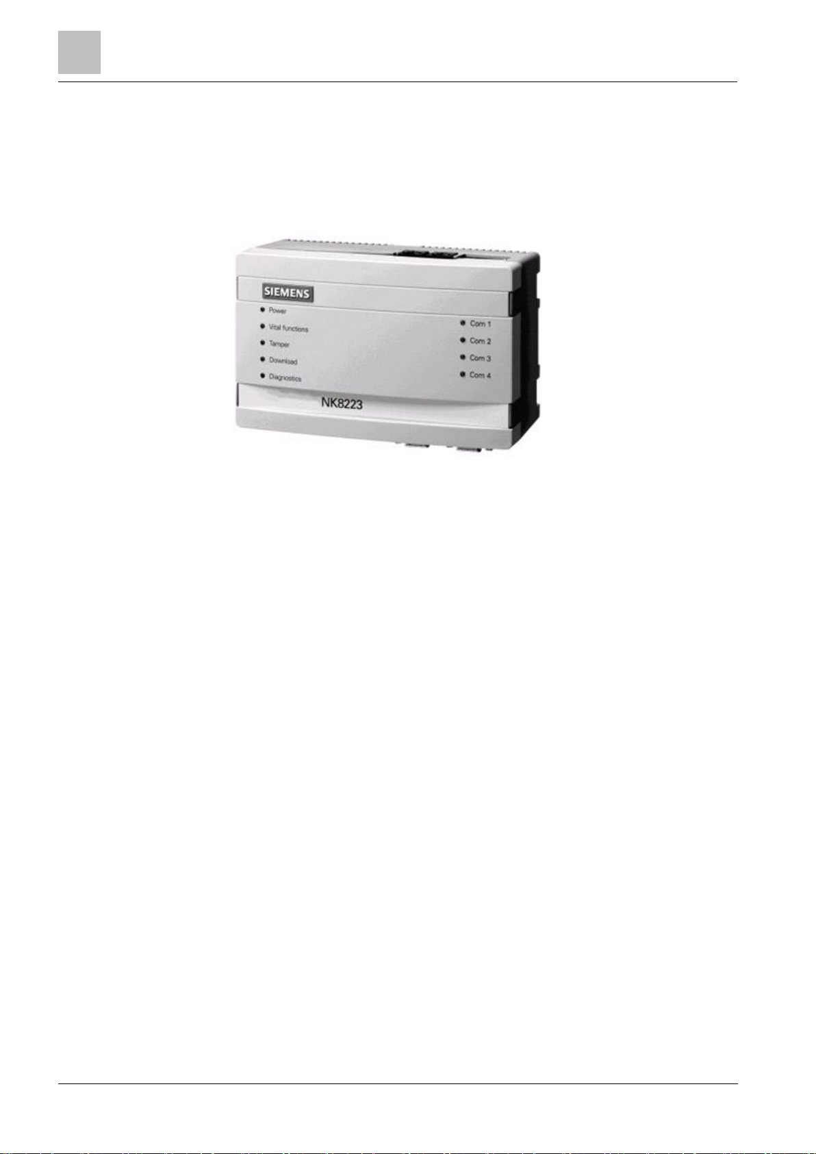
The NK822x is composed of an electronic board (with optional plug-ins) installed in
a compact and robust plastic box.
NK822x Ethernet port (NK8223 in this example)
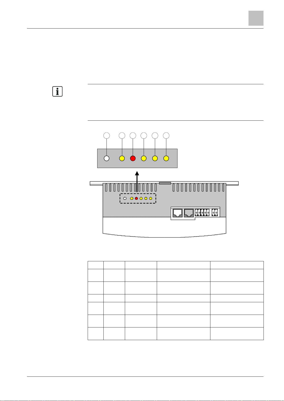
3.1.1 Front panel
The front panel houses 9 LED’s.
Left Side LED’s
The five LED’s on the left side are, from top to bottom:
Power (LED green)
Power (hardware – controlled).
Vital functions (LED green)
Software vitality:
⚫
Blinking (1 flash)
: core software running.
Tamper (LED bicolor)
Unit tamper:
⚫
Red
means tamper alarm (hardware controlled).
⚫
Green
means tamper disabled (from management station).
Download (LED red)
Network diagnostics:
⚫
Off
: status OK.
⚫
Blinking (1 flash)
: missing identification from NS8xxx.
⚫
Blinking (2 flashes)
: not used.
⚫
Blinking (3 flashes)
: FTP channel open (default mode; for switch settings see
Internal DIP Switches
.
⚫
On
: critical/hardware fault.
Diagnostics (LED yellow)
Internal interface diagnostics:
⚫
Off
: status OK.
⚫
Blinking (1 flash)
: missing or insufficient license.
⚫
Blinking (2 flashes)
: trouble with the I2C bus to I/O modules.
⚫
Blinking (3 flashes)
: trouble with the LON interface.
Structure and functions
3
NK822x hardware
19
Building Technologies A6V10062437_a_en
CPS Fire Safety
30.01.2019
⚫
Blinking (4 flashes)
: trouble with the serial/network interface.
⚫
Blinking (5 flashes)
: trouble with DLL or RCLOCK file(s).
⚫
On
: critical/hardware fault.
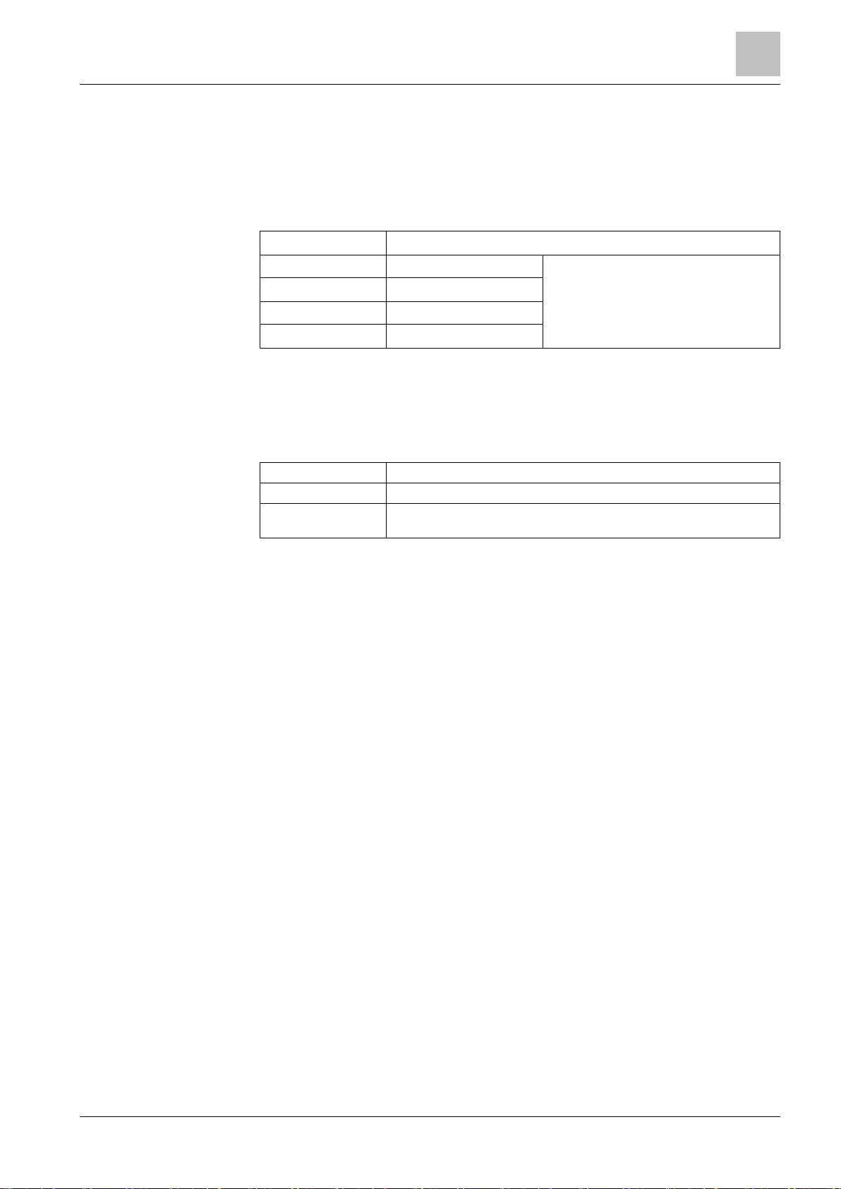
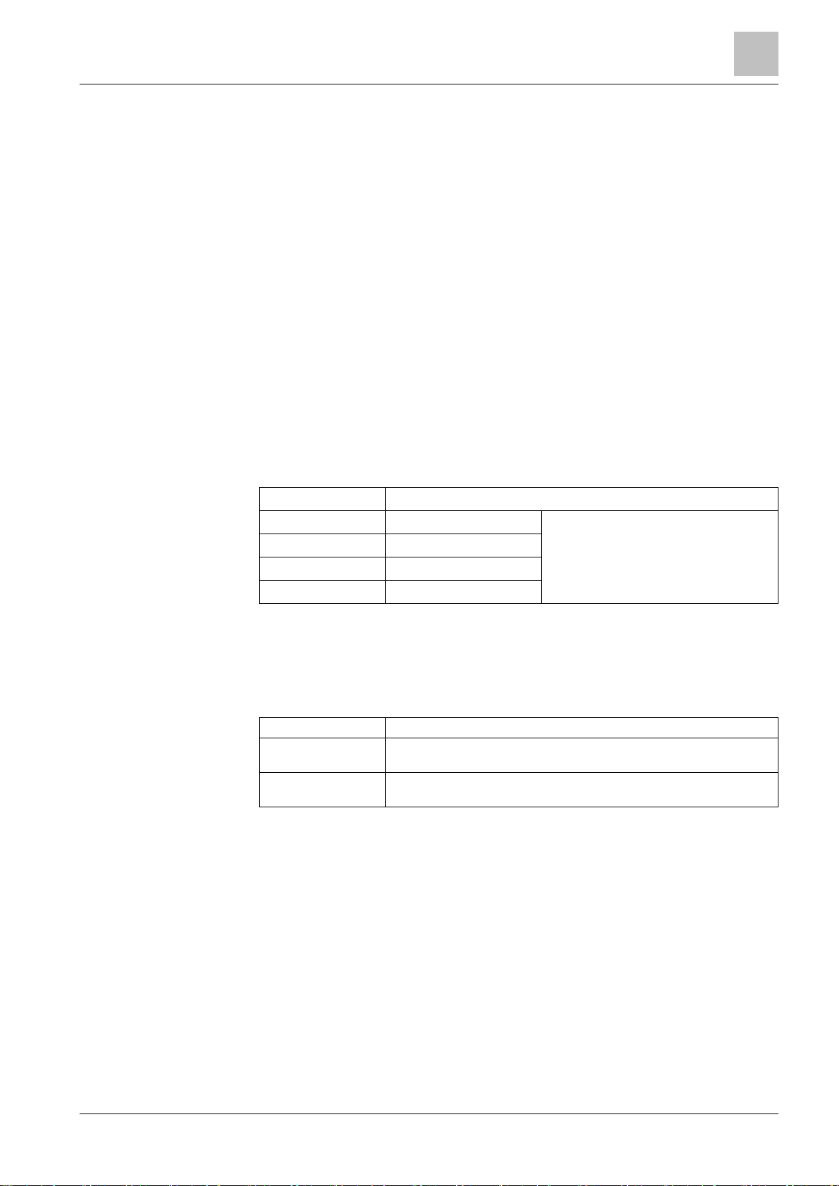
Right Side LEDs
The four LEDs on the right side are from top to bottom:
Name
Function
Com1
Status Com1
Red: RX
Green: TX
Com2
Status Com2
Com3
Status Com3
Com4
Status Com4
3.1.2 Internal DIP switches
The internal DIP switches enable a download session via FTP using a default IP
address.
Internal switch
Functions
DIP switch 1
Not used.
DIP switch 2
Default mode/network access: If DIP-switch 2 is ON, an FTP connection
occurs by default on the Ethernet at the default IP address 192.168.9.41.
3.1.3 Internal jumpers
The internal jumpers are used for:
⚫ JP3: when closed, it disables the box tamper alarm.
⚫ JP6: when closed, it enables the LON termination resistor (100 Ω) for a doubly
terminated bus topology.
3
Structure and functions
NK822x hardware
20
Building Technologies A6V10062437_a_en
CPS Fire Safety
30.01.2019
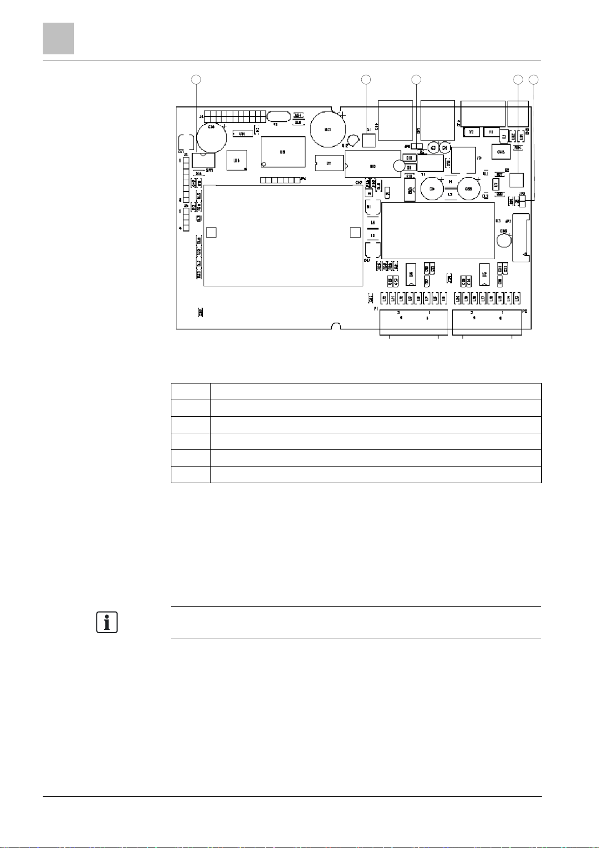
1 2 3 4 5
NK822x internal DIP switch and jumpers
Item
Description
1
DIP-Switches
2
Reset button
3
JP6: enable LON resistor.
4
Tamper switch
5
JP3: disable tamper or connect to external tamper.
3.1.4 Serial interfaces
NK8223 / NK8225: although the maximum number of serial lines is 4, they are not
always used. There are two serial lines available on the base module and two on
an expansion module.
NK8222: this model is equipped with two serial lines only available on the base
module.
Note: In all modules, the first serial port can be configured as an RS232 interface
using connector COM1 or as an RS485 interface using connector CN4.
All lines are fully RS232 compliant and have EMC/ESD protection.
No galvanic isolation is provided; all serial lines have a common ground.
Structure and functions
3
NK822x hardware
21
Building Technologies A6V10062437_a_en
CPS Fire Safety
30.01.2019
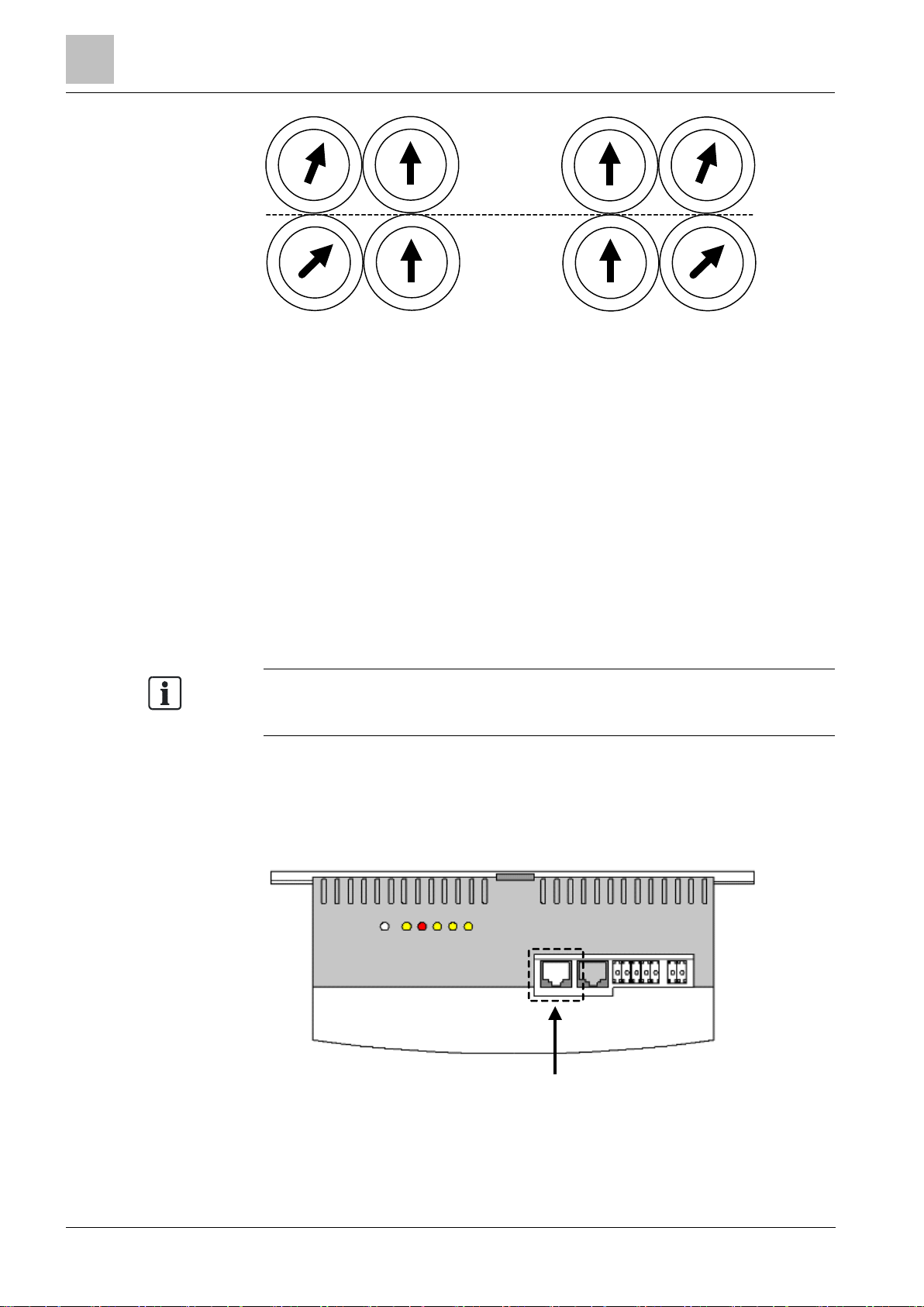
3.1.5 LON interface
3.1.5.1 PC/104 LON adapter
The NK822x processor board is equipped with a standard PC/104 interface for
system expansion. This is used for the LON add-on board.
Note: There are two revisions of LON interface boards, which have different LED
indications and different rotary switch settings.
Before checking the LEDs or setting the physical LON address with the rotary
switch, check the revision of the board you are using.
The 8-digit code (CD00251A or CD00251B) can be found on the rear of the
internal board in the upper left corner.
On the top of the NK822x module there are five LED’s and 1 push button.
1 2 3 4 5 6
Back
NK822x LN board diagnostic LEDs
Item
Name
Function
CD00251 Rev.A boards
CD00251 Rev.B boards
1
S1
Service mode
request
— — 2
DL1
(yellow)
Diagnostics
LED
Blinking if LON is faulty
Blinking if LON is faulty
3
DL2 (red)
Node in use
LED normally on
LED normally on
4
DL3
(yellow)
Service mode
LED normally on
LED normally off
5
DL4
(yellow)
RX
LED normally on, off when
receiving data
LED normally off, on when
receiving data
6
DL5
(yellow)
TX
LED normally on, off when
transmitting data
LED normally off, on when
transmitting data
At the rear of the unit, there are 4 rotary switches for LON addressing (LON
physical address).
3
Structure and functions
NK822x hardware
22
Building Technologies A6V10062437_a_en
CPS Fire Safety
30.01.2019
0
1
2
3
4
5
6
7
8
9
A
B
C
D
E
F
0
1
2
3
4
5
6
7
8
A
B
C
D
E
F
0
1
2
3
4
5
6
7
8
9
A
B
C
D
E
F
0
1
2
3
4
5
6
7
8
A
B
C
D
E
F
0
1
2
3
4
5
6
7
8
9
A
B
C
D
E
F
0
1
2
3
4
5
6
7
8
A
B
C
D
E
F
0
1
2
3
4
5
6
7
8
9
A
B
C
D
E
F
0
1
2
3
4
5
6
7
8
A
B
C
D
E
F
Subnet
Node
9
9
9
9
L H
L H
H L
H L
CD00251 Rev.A boards CD00251 Rev.B boards
Default LON address settings for communications with Guarto MP3 on NK22xx rotary
switches
LON address assignment for CS6 Guarto MP3
The LON communication between NK822x and CS6 Guarto is based on logical
BACnet addresses for both devices.
The physical LON address of the NK822x LON interface is configurable, whereas
the logical BACnet address of NK822x is fixed.
The default physical LON address of NK822x is:
⚫
Subnet
: 01
⚫
Node
: 02
The logical BACnet address of NK822x is fixed to 1. This address has to be configured in the CS6 Guarto using the tool SWE6 for Guarto MP3 (Node CerCom
Bus, properties of node Management Station).
Note: The physical LON addresses and the logical BACnet addresses must be
unique in a LON-network.
Guarto MP2b is no longer supported in NK8000 MP3.15 and higher.
3.1.6 Ethernet interface
The NK822x main board is equipped with one Ethernet interface and an RJ-45
connector. A green LED (internal) flashes when data is received or transmitted.
Back
Ethernet connector on NK822x
Structure and functions
3
NK822x hardware
23
Building Technologies A6V10062437_a_en
CPS Fire Safety
30.01.2019
3.1.7 I2C interface: I/O and power supervision
This interface allows for a direct support of:
⚫ Direct digital input/output:
– One or two DF8040 (CF9040) input modules
– One DF8020 (CF9020) output module
⚫ Power supply supervision:
– One DF8090 power supply supervision module
All modules can be installed on the DIN-rail, next to NK822x unit.
DF8020
DF8020 is a module providing 8 relay outputs, NO or NC.
DF8040
DF8040 is a module providing 8 inputs, which can be normally open or normally
closed and driven by dry contacts or open collector signals
See NK822x hardware installation [➙ 36] for more information on the connection of
I/O modules to the NK822x
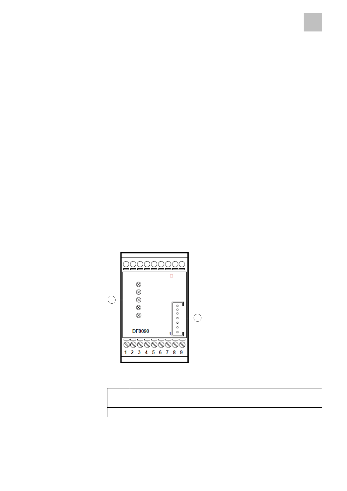
DF8090 Power Supply Supervision
DF8090 is a module designed for monitoring a 12V DC power supply. It can detect
the conditions listed below, shown on the DF8090 local panel and report them to
NK822x, and in turn to management station (see the following):
⚫ Mains failure (no 220VAC)
⚫ Battery low
⚫ Power supply failure (trouble with AC/DC converter)
⚫ Battery protection fuse blown (internal micro-fuse type MSF 3.15A/250V)
1
2
PW
MAINS
AC/DC
LOW BATT
BATT FUSE
DF8090 front panel
Item
Description
1
LEDs.
2
I2C connector to I/O modules.
See figure
NK822x power connections
(see NK822x hardware installation [➙ 36])
for the NK822x power connections using the power supervision module.
3
Structure and functions
NK823x hardware
24
Building Technologies A6V10062437_a_en
CPS Fire Safety
30.01.2019
For more information about the DF8000 Input/Output modules, including
installation details, see documents
DF8000 Datasheet (document
no.A6V10081184)
and
DF8000 ICC (document no.A6V10081388)
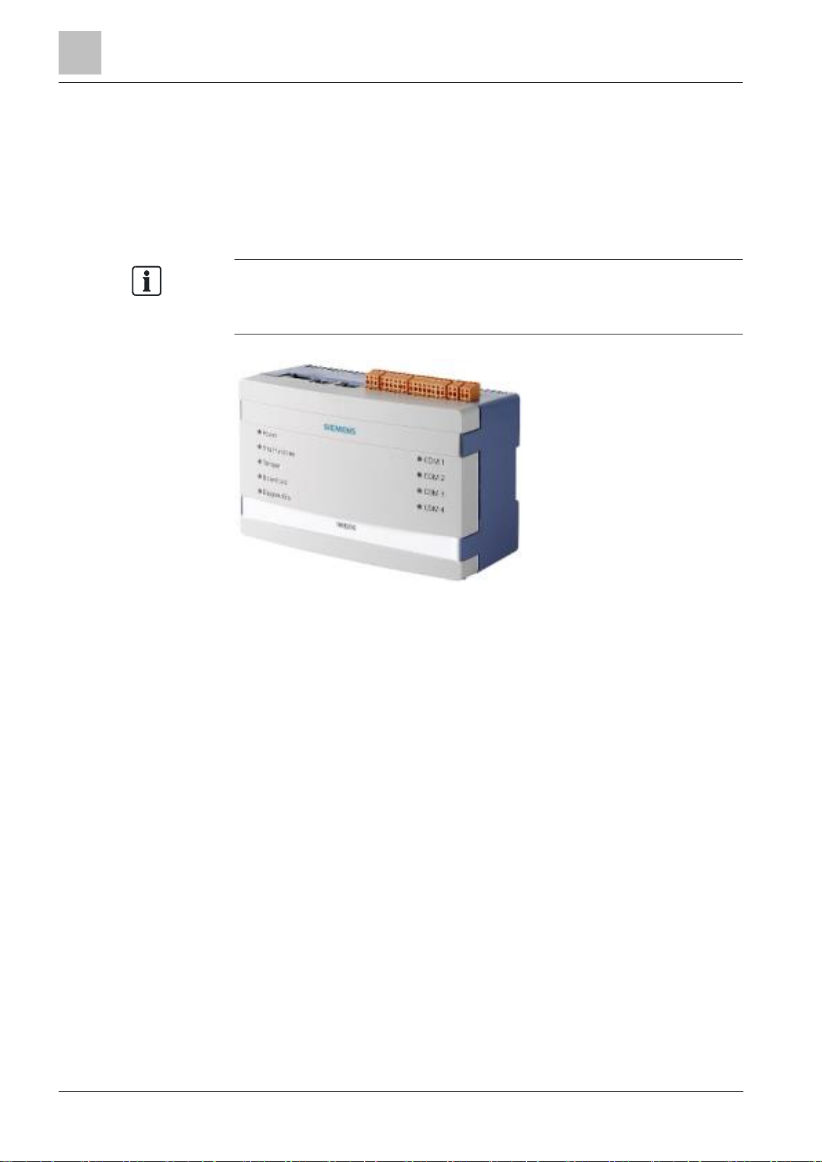
3.2 NK823x hardware
The NK823x is composed of an electronic board (with optional plug-ins) installed in
a compact and robust plastic box.
Note: NK823x units with build state up to 04 are equipped with the NKM8001-A1
mainboard that do not support locally connected DF8000 I/O modules.
Instead, NK823x units with build state 10 or higher are equipped with the
NKM8001-A2 mainboard that can support up to 4 locally connected I/O modules.
NK823x Ethernet port unit (NK8235 in this example)
3.2.1 Front panel
The front panel houses 9 LED’s.
Left Side LEDs
The five LEDs on the left side are from top to bottom:
Power (green LED)
Power (hardware – controlled).
Vital functions (green LED)
Software vitality:
⚫
Blinking (1 flash)
: core software running.
⚫
Blinking (2 flashes)
: core software running and logging function active.
Tamper (bi-color LED)
Unit tamper:
⚫
Red
means tamper alarm (hardware controlled).
⚫
Green
means tamper disabled (from management station).
Download (red LED)
Network diagnostics:
⚫
Off
: status OK.
⚫
Blinking (1 flash)
: missing identification from NS8xxx.
⚫
Blinking (2 flashes)
: not used.
⚫
Blinking (3 flashes)
: FTP channel open (default mode; for switch settings see
Internal DIP Switches
.
Structure and functions
3
NK823x hardware
25
Building Technologies A6V10062437_a_en
CPS Fire Safety
30.01.2019
⚫
On
: critical/hardware fault.
Diagnostics (yellow LED)
Internal interface diagnostics:
⚫
Off
: status OK.
⚫
Blinking (fast)
: booting operating system after restart.
⚫
Blinking (1 flash)
: missing or insufficient license.
⚫
Blinking (2 flashes)
: trouble with the I2C bus to I/O modules.
⚫
Blinking (3 flashes)
: not used
⚫
Blinking (4 flashes)
: trouble with the serial/network interface.
⚫
Blinking (5 flashes)
: trouble with DLL or RCLOCK file(s).
⚫
Blinking (6 flashes)
: Modbus GW trouble.
– SW trouble.
– No communication to FS20/FS720 or to the Modbus Master/Client.
– No NK8237 or FS20/FS720 registers reading (Modbus Master watchdog
expired).
⚫
On
: critical/hardware fault.
Right Side LEDs
The four LEDs on the right side are from top to bottom:
Name
Function
Com1
Status Com1
Red: RX
Green: TX
Com2
Status Com2
Com3
Status Com3
Com4
Status Com4
3.2.2 Internal DIP switches
The internal DIP switches (S101) enable a download session via FTP using a
default IP.
Internal switch
Functions
DIP switch 1
Default mode/network access: If DIP switch 1 is ON, an FTP connection
occurs by default on the Ethernet 1 at the default IP address 192.168.9.41.
DIP switch 2
Default mode/network access: If DIP switch 2 is ON, an FTP connection
occurs by default on the Ethernet 2 at the default IP address 192.168.10.41.
3
Structure and functions
NK823x hardware
26
Building Technologies A6V10062437_a_en
CPS Fire Safety
30.01.2019
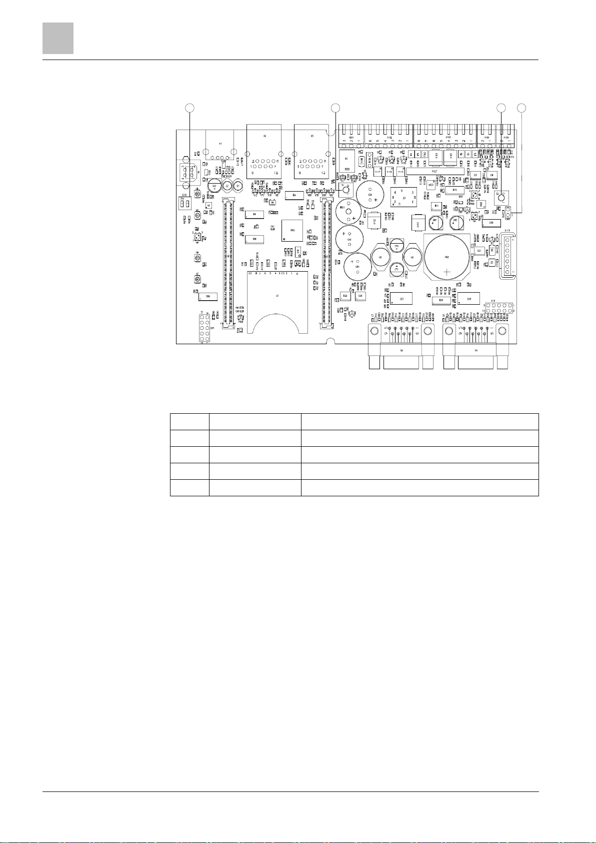
3.2.3 Internal jumpers
1 2 3
X1 X2 X3 X101 X102 X103 X104 X105
X111
4
Internal DIP switch and jumpers (NKM8001-A1 mainboard)
Item
Name
Description
1
S101
DIP-Switches
2
S1
Reset button
3
S2
Tamper switch
4
X115
When closed, it disables the box tamper alarm.
 Loading...