

Siemens DMS8000, NK8000, MM8000, MK8000 Application & Planning
DMS8000 MP
4.81
Application & Planning
For:
- MM8000 Management Station
- MK8000 OPC Server
- NK8000 Networks
With WW8000 Composer
Building Technologies
CPS Fire Safety

Copyright Noti ce
Docum ent information is subj ect to change w ithout notice by Siemens Switzerland Ltd. Compani es, names, and various data used in
examples are ficti tious unless otherwise noted. No part of this document may be reprod uced or transmitted in any form or by any means ,
electronic or mechanical, for any purpose, without the expr ess written permissi on of Siemens Swi tzerland Ltd. All software described in this
document is furnished under a license agr eement and may be used o r copied only in accordance with license terms . For further informati on,
contact your nearest Siemens Switzerland Ltd. representative.
© Siemens Switzerland Ltd, 2016

About this document ...........................................................................................5
1 Introduction – products concept.........................................................8
1.1 Danger management systems ...............................................................8
1.2 Conne ctivity – NK8000 netwo rks ............................................................9
1.2.1 Which NK8000 Ethernet Port to choose?..................................9
1.2.1.1 NK82xx standard connectivity capabilities and common
feature s ...................................................................................9
1.2.1.2 Enhanced connectivity capabilities for NK8232/NK8235 ......... 10
1.2.1.3 Extended connectivity and other capabilities for NK823x only . 10
1.3 Configu ration – WW8000 Compos er .................................................... 10
1.4 What’s new .......................................................................................... 11
2 Managem ent level configurati ons ..................................................... 12
2.1 MM8000 Management Station/MK8000 OPC DA/UA Server
configurations ...................................................................................... 12
2.1.1 Stand-alone configurations ..................................................... 12
2.1.2 Peer to peer ........................................................................... 13
2.1.3 Distribu ted cl ient/ser ver con figurat ions ................................... 13
2.2 Suppo rt of mob ile device s .................................................................... 19
2.2.1 Nationa l standard s, regulation s and legislation ....................... 19
2.2.2 Mobile devices connected via WLAN wireless network ........... 20
2.2.3 Mobile devices connecte d via Internet .................................... 21
2.2.4 Mobile devices connecte d via UMTS ...................................... 22
2.3 NK800 0 netw ork configurations ............................................................ 23
2.3.1 DMS800 0 Multiple hos t configura tion – CMSDL/IP ................. 23
2.3.2 DMS800 0 multip le host configu ra tion – BACnet /IP ................. 23
2.3.3 Modbus Gateway for fire applications and network separation 24
2.3.4 DMS8000 multiple or single host – network redundancy with
dual LAN ................................................................................ 25
2.3.5 DMS800 0 – supp ort of dial-up con ne ct ion s ............................ 26
3 Automa tion level confi gurations ....................................................... 27
3.1 Configu ration s supported by MM800 0/MK80 00 .................................... 27
3.2 Configuration types .............................................................................. 29
3.2.1 ISO1745 direct configura tion .................................................. 29
3.2.2 Cerloop configuration ............................................................. 31
3.2.3 CS111 5/FC33 0A direct configurat ion ..................................... 33
3.2.4 SI410/4 20 direct con figuration ................................................ 34
3.2.5 SPC 4000/500 0/60 00 LAN configuration ................................ 36
3.2.6 Acces s contro l LAN configurat ion ........................................... 37
3.2.7 BACnet/IP LAN configura tion ................................................. 39
3.2.8 Video LAN con figuration ......................................................... 42
3.2.9 Remote notifica tion configu rat ion ........................................... 44
3.2.10 OPC DA integration configu ration ........................................... 45
3.2.11 NK82xx serial configura tion .................................................... 47
3.2.12 NK82xx LAN/ WAN con figurat ion ............................................ 50
3.2.13 NK823 x Etherne t Port with BACne t con figurat ion ................... 53
3.2.14 NK823x: Modbus Gateway configuration for
FS20/FS720/STT20 ............................................................... 56
3.3 NK8000 Networks ................................................................................ 59
3.3.1 Product overview ................................................................... 59
3.3.2 Installat ion ............................................................................. 61
Building Technologies 049_DMS_DMS8000_Application_Specification_Planning_MP4.81_A6V10063710_a_en.doc
CPS Fire Safety 09.2016
3

3.3.3 Subs ystem conne ctivity solutions ........................................... 6 2
3.3.3.1 Subs ystems conn ected via BACnet ........................................ 63
3.3.3.2 Subs ystems connected via RS232 interface ........................... 64
3.3.3.3 Subs ystems connected via RS485 interface ........................... 65
3.3.3.4 Subs ystems conn ecte d via USB LON interface ...................... 66
3.3.3.5 Cerloop netw ork conn ecte d via MK7022 ................................ 67
3.3.3.6 Power supply supervision and digital I/O-modules connect ed
via I2C-bus ............................................................................. 68
3.4 3rd party sys tems ................................................................................. 69
4 NK800 0 applicatio n example s ........................................................... 70
4.1 Local sys tem........................................................................................ 70
4.2 Distribu ted, campus-s tyle sys tems ....................................................... 71
4.3 Wide area extens ion sys tems .............................................................. 72
4.4 Interactions .......................................................................................... 73
5 NK800 0 network plann ing ................................................................. 75
5.1 NK8000 Security .................................................................................. 75
5.2 IT rules ................................................................................................ 76
5.2.1 Repea ter rules ....................................................................... 76
5.2.2 Cable lengths ......................................................................... 77
5.3 Dedicate d safety and secu rity netw o rks ............................................... 78
5.3.1 Application example with commercial Ethernet components ... 78
5.3.2 Application example with Industrial Ethernet components ....... 80
5.3.3 Application example with Open Transport Network (OTN) ...... 82
5.4 Shared netwo rk ................................................................................... 83
5.4.1 Informat ion you ne e d to give to you r cus tomer ....................... 84
5.4.2 Securit y and applica tion port numbers .................................... 84
5.4.3 Netw ork bandwidth................................................................. 8 5
5.5 Datalink character istics ........................................................................ 85
5.5.1 LON ....................................................................................... 85
5.5.2 Serial interface (RSxxx) .......................................................... 8 6
5.5.3 Modems ................................................................................. 86
5.5.4 Ethernet ................................................................................. 86
5.5.5 FDDI/CDD I ............................................................................ 8 7
5.5.6 xDSL...................................................................................... 88
6 Licenses ............................................................................................. 88
Appendix A – DMS8000 networ k conne ctivity opt io ns .................................... 89
Appendix B – Checklist ..................................................................................... 91
4
Building Technologies 049_DMS_DMS8000_Application_Specification_Planning_MP4.81_A6V10063710_a_en.doc
CPS Fire Safety 09.2016

About this document
Scope
This document applies to the following Siemens DMS8000Danger Management System products:
- MM8000 Management Station
- MK8000 OPC Server for Subsystems
- NK8000 Networks
(With WW8000 Composer)
Target audience
This documentation is intended for the following users:
Sales Representat ives are the first contact to the customer’s buying center who es-
tablish the rel ationship. During pre-sales, they present the system to potential customers, focusi ng on unique selling propositions and benefits i n order to acquire the project.
Sales Engineers provide pre- and post-sales technical advice and high-level support
on product applications and solutions. They are often the key point of contact for clients, answering questions, providing technical advice and design solutions. They hav e
extensive knowledge of the products as well as the application and network environments.
Introduction – product s concept
Liability disclaimer
We have checked the contents of this manual for agreement with the hardware and
software described. Since deviations cannot be precluded entirely, we cannot guarantee full agreement. However, the data in this manual are rev iewed regularly and any
necessary corrections are included in subsequent editions. Suggestions for im provement are welcome. Brand or product names mentioned in this document may be
names protect ed by copyright law or registered trademarks of other companies. These
are mentioned only for identification purposes and have no recommendatory character
in regard to the product or manufacturer, unless otherwise stated.
Security Disclaimer
Products, solut ions and services from Siemens include security functions to ensure
the secure operation of building automation and control, fire safety, security management, and physical security systems. The security functions on these products, solutions and services are important components of a comprehensive security concept.
Drafting, implementing and managing a com prehensive and up-to-date security concept, customized to individual needs, is nevert heless necessary, and may result in additional plant- or site-specific preventiv e m easures to ensure secure operation of your
site regardi ng building automation and control, fire safety, security management, and
physical security. These measures may include, for example, separating networks,
physically protecting system components, user training, multilevel defensive measures, etc. For additional information on security as part of building technology and our
product, solution and service offerings, please cont act your Siemens sales representative or project department. We strongly recommend to always comply with our security
advisories on the latest security threats, patches and other related measures.
http://www.siemens.com/cert/en/cert-security-advisories.htm
Building Technologies 049_DMS_DMS8000_Application_Specification_Planning_MP4.81_A6V10063710_a_en.doc
CPS Fire Safety 09.2016
5

Introduction – product s concept
Documentation resource information
The DMS8000 Documentat ion Resource Information and Glossary Guide assembles
important information regarding docum entation resources. This document contains the
following:
To access the DMS8000 Documentat ion Resource Information and Gloss ary Guide
(document no. A6V10089056), go to the link and follow the document search instructions below:
http://assetportal.bt.siemens.com /portal/index.html
- Com prehensiv e definitions of the target audiences for Siemens FS DMS docu-
ments
- Trai ning program information including the Siemens intranet link
- A complete list of all available DMS8000 documents
- I nstructi ons for how to obtain a document vi a the Siemens intranet using the
Siemens Asset Portal
- A map of relevant documents for each target audience group
- Customer Support links & resources
- A glossary containing definitions of all terms and acronyms used in DMS8000
documentati on
1. In the Search column on the left, set:
- Segment: 04 Fire -3F
- Document Type: All
- Image Type: All
- Advanced search criteria: Select Brochure No. and enter the document num-
ber to search for (e.g. A6V10062415). Alternatively, select Title and enter the
product name (e.g. MM8000).
2. Click Search to start.
· In the resulting area on the right, select the document type (e.g. Contacts, Data
Sheet, etc).
For more information such as Siemens news and announcements, visit the STEP
Web portal at:
https://workspace.sbt.siemens.com/content/00001123/def ault.aspx
Modifica tion index
Current version Date Notes
A6V10063710_a_en 09.2016 For details on updates/modifications to the 17th Application &
A6V10063710_a_en 09.2015 16th Application & Planning edition for all Siemens DMS, Net-
A6V10063710_a_en 09.2014 15th Application & Planning edition for all Siemens DMS, Net-
Planning edition, see What’s new in s ec tion 1.4, p. 11
work, and 3rd party products (MP4.80)
- Removed MT800 1 terminal
- Removed NK822x Ethernet ports
- Removed CF9000 I/O units
- Removed NE8002 cabinet
- Removed NZ8202 and NZ820 3 mounting kits
- Improv ed and harm onized images
- Removed “Intrunet” from intrusion panels name
work, and 3rd party products ( MP4.70)
- CS6 connectivity on NK823x
- Web and mobile client connectivity (Web Services)
- Mimic display client
- Support for Windows Hyper-V virtual environment
- NK823x firewall and router with dynamic routing
6
Building Technologies 049_DMS_DMS8000_Application_Specification_Planning_MP4.81_A6V10063710_a_en.doc
CPS Fire Safety 09.2016

Introduction – product s concept
Current version Date Notes
- NK823x Web Server for monitoring and configuration
- FTP passive mode supported
A6V10063710_a_en 06.2013 14th Application & Planning edition for all Siemens DMS, Net-
A6V10063710_a_en 06.2012 13th Application & Planning edition for all Siemens DMS, Net-
A6V10063710_a_en 06.2011 12th Application & Planning edition for all Siemens DMS, Net-
A6V10063710_b_en 12.2010 11th Application & Planning edition for all Siemens DMS, Net-
A6V10063710_a_en 06.2010 10th Application & Planning edition for all Siemens DMS, Net-
A6V10063710_b_en 12.2009 9th Application & Planning edition for all Siemens DMS, Network,
work, and 3rd party products ( MP4.60)
Updates inc l ud e:
– XLS panel support by MK8000
– NK823x:
– SD card supporting memory expansion for logging storage
– STT20 BACnet connectivity support
– Support of large Si nteso (Cerberus PRO)/STT20 systems
– Enhanced firewall support (Edge FW Advanced)
– BACnet/I P connectivity limitations
– NK8235: Up t o 32 Modbus panels supported on RS485
work, and 3rd party products ( MP4.50)
Updates inc l ud e:
– NK823x:
– Dual Ethern et interface supporting redundancy and net-
work s eparation; also routing and firewall functions
– USB port s upporting memory exp ansion for logging storage
– Modbus G ateway for multiple M odbus clients, devices
– Support of two ups tream CEI 79- 5 hosts
– STT20 BACnet connectivity support by MM8000/MK8000
– Enhanced Bosch video device support
– ONVIF-compliant camera support
– Architectur al drawing u pd ates accord ing to new MM8000 UI
– MT 8001 Manag ement Terminal phased out
– Siemens Building Technologies now in Siemens Infrastruc-
ture and Cities Sector
work, and 3rd party products ( MP4.40)
Updates inc l ud e:
– New Bosch video subsystem support (MM8000)
rd
– 3
party generic DVR support via OPC (MM8000)
– Sup port for up to 15 clients (MM8000 / MK 8000)
– NK823x support of FS20/FS720
– NK823x acts as FS20/FS720 M odbus Gateway for 3
rd
party
Modbus stations/devices
– New NK8237 Modbus Gateway
– New application port number for NK823x secure download
– SNMP support (NK823x only)
work, and 3rd party products (MP4.30-01)
Updates inc l ud e:
– Documentation pertaining to NK823x product enhancements
MP4.30-01
– Docu m entation pertaining to M M8000/MK 80 00 product en-
hancem ents MP4.30-0 1
work, and 3rd party products (MP4.30)
Updates inc l ud e:
– MM8000 multiple server support
– NK823x dual Ethernet interface for redundant networking
– NK823x onbo ard digital I/Os
– NK823x support of CS115/FC330A
– NK822x remote tunnelling for CS6 Guarto
– Management level configurations section content enhanced
and restructured
– Ill us tration upd at es
and 3rd party products (MP4.20-01)
Updates inc l ud e:
– Documentation pertaining to release of NK823x products
MP4.20-01
Building Technologies 049_DMS_DMS8000_Application_Specification_Planning_MP4.81_A6V10063710_a_en.doc
CPS Fire Safety 09.2016
7

Introduction – product s concept
1 Introduction – products concept
One of Siemens Infrastructure and Cities Sector, Building Technologies Divisions’ (IC
BT) primary goals is to be able to provide complete int egration solutions to our customers. Compl ete integration includes fire safety, security, and building automation
systems built by various Siemens and third-part y suppliers.
As the needs and expect ations of the market continue to advance at the pace of technology, IC BT aims to provide products that meet those needs and expectations.
Siemens’ family of products are designed to serve the market for small to medium-size
local systems, campus-size configurations (LAN applications), and for geographical
networks (WAN applications). Additionally, in cases where another supplier is making
the integration, Siemens provides open system solutions enabling integration of our
subsystems.
See the following to determine which product or combination of products best suit your
customer’s needs.
1.1 Danger management systems
Siemens offers the following Danger Management System (DMS) solutions:
· MM8000 Management Station:
The MM8000 provides integrated management and handling, decentralised system
operation and centralised maintenance. The MM8000 is designed to replace older
management stati ons such as LMSmodular, LMS6, and DMS7000.
MM8000 also offers the following advantages:
- Flexibility – The system can be built and configured to fit different situations.
- Scalability – MM8000 will easily grow to support more subsystems, disciplines,
and stations as needed.
- Reliabi lit y – The MM8000 is based on the concept of autonomous subsystems
and distribut ed control. Furthermore, redundant configurations can be implemented.
- Security – The operator will have access to exactly what is defined.
- 3rd Party integration – The MM8000 arc hitecture allows for open system solu-
tions and for the integration of 3rd party devices.
· MK8000 OPC Server for Subsystems:
The MK8000 OPC Server product concept provides open system solutions to our
customers, enabling our subsystems to be integrated into 3rd party management
systems.
The objective is to offer the OPC Data Access (DA) or Unified Architecture (UA)
Server product in parallel with complete offerings including our MM8000 management station software.
The OPC DA/UA Server product allows us to technically integrate FS subsystems
into building automation unit head-ends, thereby supporting the IC BT Total Building Solutions offering.
8
Building Technologies 049_DMS_DMS8000_Application_Specification_Planning_MP4.81_A6V10063710_a_en.doc
CPS Fire Safety 09.2016

1.2 Connectivity – NK8000 networks
NK8000 connects various subsystems via TCP/IP or BACnet/IP over Ethernet or serial
connectivity with the MM8000 and the MK8000 systems.
The following make up the NK8000 product family:
· NK823x (second generati on of NK8000 Ethernet Ports):
- NK8232 Ethernet Port for a single subsystem for DMS8000 systems
- NK8235 Ethernet Port f or DMS8000 systems
- NK8237 Modbus Gateway for Sinteso and Cerberus PRO fire detection sys-
tems
1.2.1 Which NK8000 Ethernet Port to choose?
The NK82xx Ethernet Ports are used to connect local and distributed safety and security devices to DMS8000 Management Stations. The Ethernet Por t provides a first
level of centralisation, and acts as a secure communication partner for DMS8000. All
ports come with optional housing solutions with autonomous power suppl ies.
NK823x, incl uding the products NK8232, NK8235, and NK8237, is the second generation of Ethernet Por ts. NK823x is based on a new more powerful HW platform and can
replace the NK822x products. NK8232 is backward compatible with NK8222, and
NK8235 is backward compat ible with NK8223 and NK8225.
The NK8232 allows connecti on of a single safety or security subsystem to DMS8000
Management Stations, and is best suited for distributed systems or geographical networks where only one subsystem needs to be connected to a remote management
system (such as a bank application: centralisation of security systems of branches).
The NK8235 allows connection of multiple IC BT and 3rd party subsystems to
DMS8000 Management Stations, and is best suited for local systems, campus-size or
wide area extension systems, where more than one subsystem has to be connected,
or system extensions with additional subsystems are ex pected.
The NK8232/NK8235 offers, in addition to the standard connectivity capabilities,
BACnet connectiv ity between NK823xs for network-wide interactions and to DMS8000
hosts.
The NK8237 is used as a gateway between Sinteso(or Cerberus PRO)/ STT20 fire detection systems and Modbus head-end/automation systems on LAN or over a serial
line. It provides for bi-directional Modbus RTU and TCP/IP connectivity to Sinteso or
Cerberus PRO and STT20 fire detection systems.
Introduction – product s concept
1.2.1.1 NK82xx standard connectivity capabilities and common features
· TCP/IP on Ethernet connectivity for connection to local and remote management
stations. Transport protocol CMSDL/IP, BACnet/IP, or CEI 79-5/IP featuring 64-bit
encryption (FEAL algorithm) for high security banking applications, and support of
switched lines.
· Simult aneous multiple host connectivit y (up t o four) using CMSDL/IP protocol
(without encryption).
· Upstream serial connectivity to a local management station (MM8000/MK8000) using an RS232 line via CMSDL serial protocol.
· The upstream devices (MM8000 or MK8000) must be equipped with the
NS8011/NS8210 Network Driver for TCP/IP on Et hernet connectivity or with the
NS8012 CDI-Net Driver for serial connectivity.
Building Technologies 049_DMS_DMS8000_Application_Specification_Planning_MP4.81_A6V10063710_a_en.doc
CPS Fire Safety 09.2016
9

Introduction – product s concept
· Direct support for digital I/O modules connected via I2C bus.
- Up to 32 non-superv ised digital inputs
- Up to 32 non-supervised digital relay outputs
- Up to 16 bal anced input s
· Interaction machine supporting logical combinations between local ly connected
subsy ste ms
® See secti on 4.4 on page 73 for subsystems supported.
· Optional dial-up connectivity via modem for wide area extension systems.
1.2.1.2 Enhanced connectivity capabilities for NK8232/NK8235
· Standard connectivity capabilities as mentioned in 1.2.1.
· BACnet/ IP on Ethernet connectivity for connection to local and remote DMS8000
management stati ons.
® See section 3.2. 13 on page 53 for subsystems supported.
· Enhanced network-wide interaction machine supporting logical combinations be-
tween subsystems connected to ot her NK823xs.
® See more about interac ti ons in section 4.4 on page 73.
· The DMS8000 upstream devices (MM8000 or MK8000) must be equipped with the
NS8011 Network Driver for BACnet/IP on Ethernet connectivity, the NS8210 Network Driver for TCP/IP on Ethernet connectivity, or with the NS8012 CDI-Net
Driver for serial connectivity.
1.2.1.3 Extended connectivity and other capabilities for NK823x only
· Support of FS20 Sinteso™/FS720 Cerberus© PRO and STT20 fire panels.
· 3rd party Modbus system support for FS20/FS720 and STT20 systems where
NK823x serves as Modbus Gateway.
· Dual Ethernet interface supporting redundancy and network separation; also routing and firewall functions
· USB port and SD card slot supporting memory expansion for logging storage of selectable data flow (upstream and/or downstream).
1.3 Configuration – WW8000 Composer
MM8000, MK8000, and NK8000 can be configured in a fast, safe, and easy way with
Composer (using the subsystem tool concept). Composer is the comm on configuration tool for all DMS8000 products.
® For more inf ormation on Siemens DMS product s, see the Documentation resource
information section on page 5.
10
Building Technologies 049_DMS_DMS8000_Application_Specification_Planning_MP4.81_A6V10063710_a_en.doc
CPS Fire Safety 09.2016

1.4 What’s new
Introduction – product s concept
The following is a list of modifications included in MP4.81 for new functions and software improvements.
Modifica tion index
Section Modifica tion
Security Disclaimer inserted
5.1 New section NK8000 Security
5.4.2 List of NK823x port numbers updated
Building Technologies 049_DMS_DMS8000_Application_Specification_Planning_MP4.81_A6V10063710_a_en.doc
CPS Fire Safety 09.2016
11
Management level configurations
2 Management level configurations
This section lists the management configuration types that are supported in DMS8000
MP4.81 for:
- MM8000 Management Station
- MK8000 OPC Server
- NK8000 Networks
To see network connectiv ity options, refer to Appendix A.
2.1 MM8000 Management Station/MK8000 OPC DA/UA Server configurations
The following management configuration types are supported by MM8000/MK8000.
Examples show the different site configuration options available. These configurations
can be for one or multiple stations or sites.
Note: Management Station configurations can be freely combined with NK8000 network configurations. (See section 2.2.)
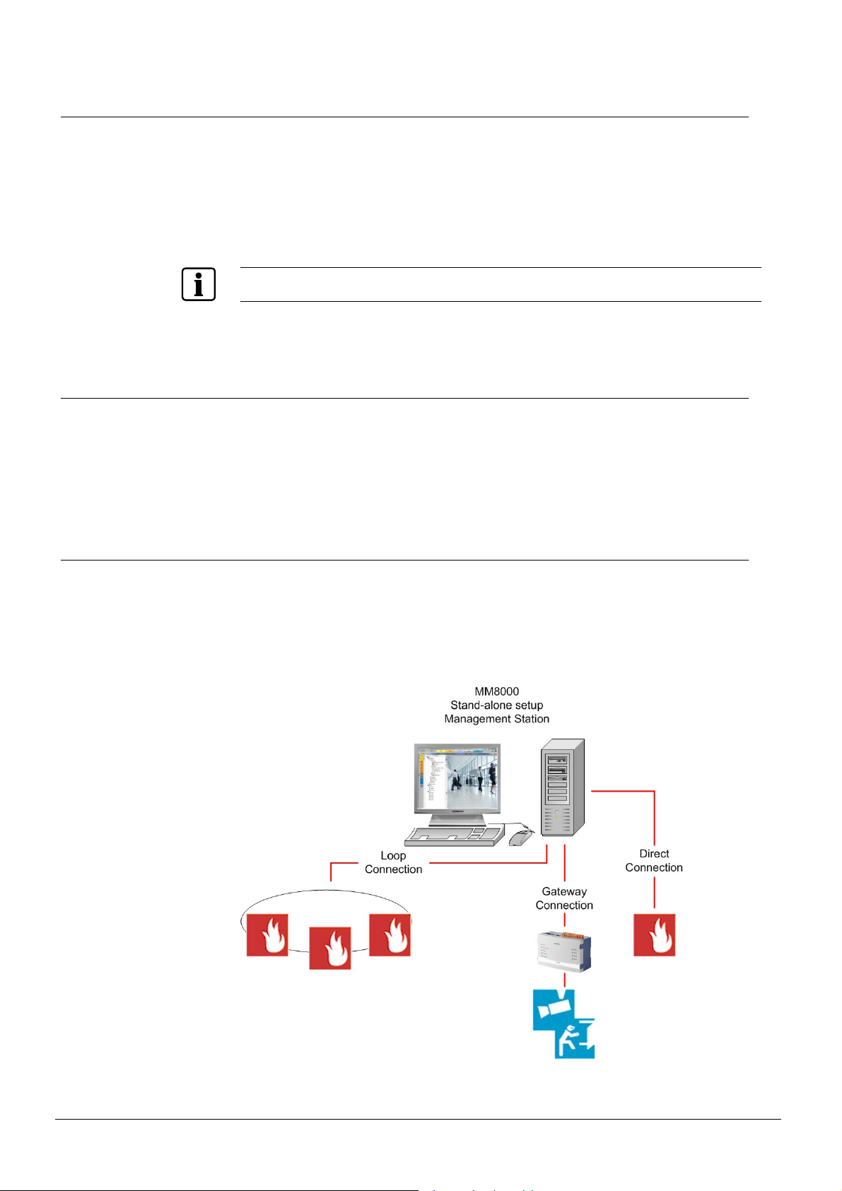
2.1.1 Stand-alone configurations
Characteristics:
- St and-alone station that contains all software levels (Client and Server)
- Prov ides a straightforward solution for small and medium-size systems
Fig. 1 MM8000 Stand-alone setup configuration
12
Building Technologies 049_DMS_DMS8000_Application_Specification_Planning_MP4.81_A6V10063710_a_en.doc
CPS Fire Safety 09.2016
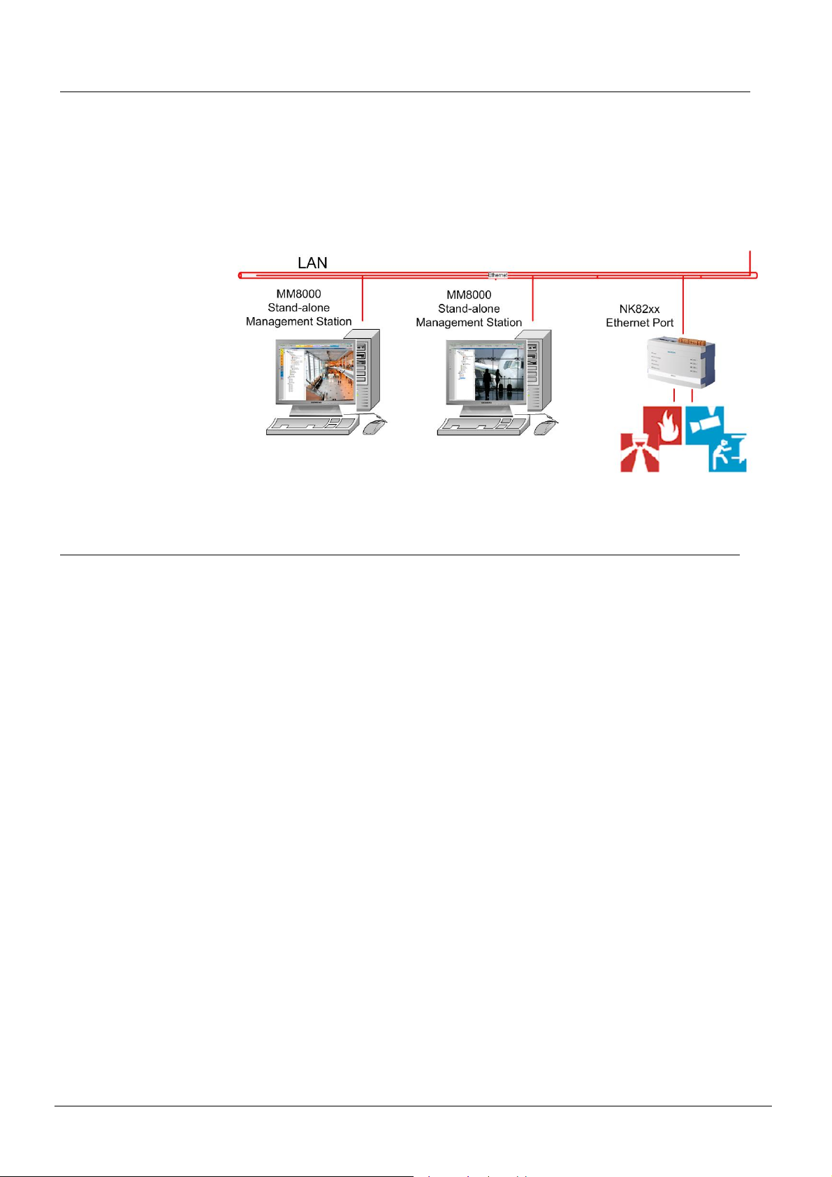
2.1.2 Peer to peer
Management level configurations
Characteristics:
- Eac h station is a stand-alone, and therefore contains all the software layers (client, server, and communication)
- T he stations can be connected to the communication level configurations, e.g.
NK82xx Ethernet ports, which allow multiple routing.
Fig. 2 Peer-to-peer configuration
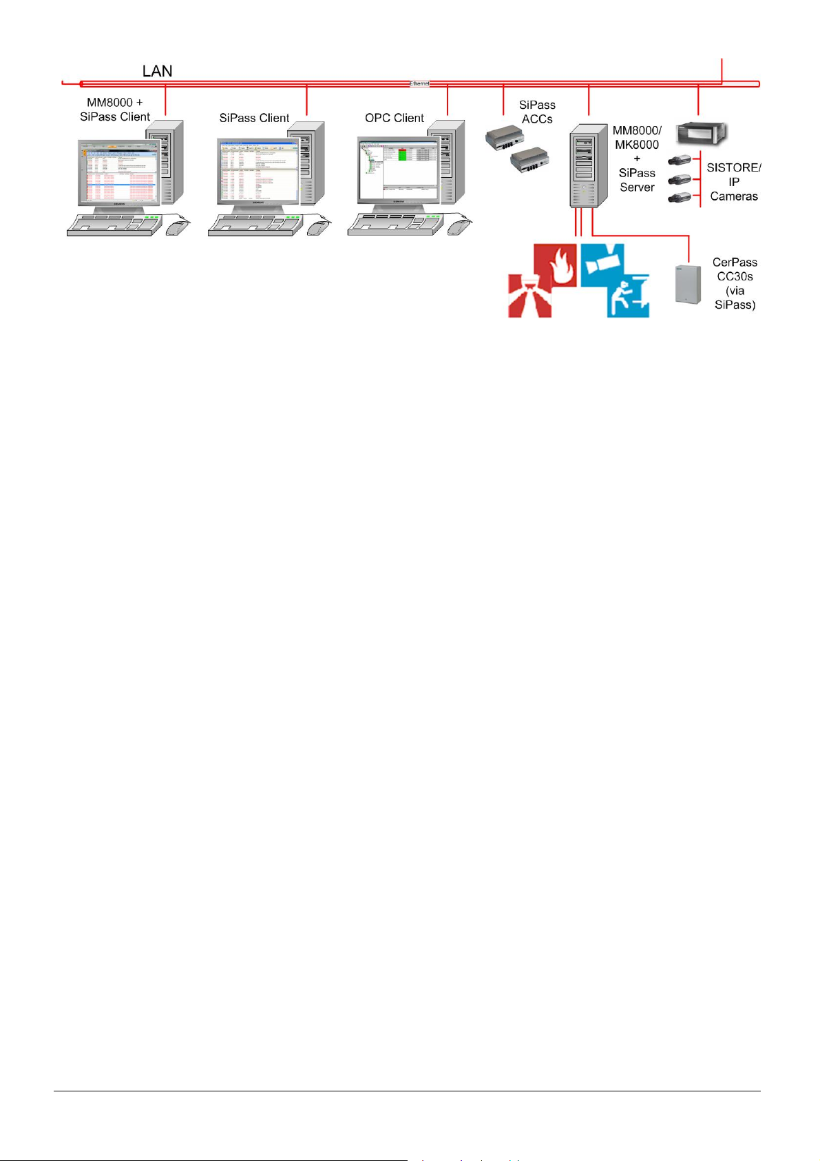
2.1.3 Distributed client/server configurations
Characteristics:
- Distri buted client and server communicate via TCP/IP connection
- Prov ides a straightforward solution for small and medium-sized systems
- Suppor t of up to 15 client connections, including MM8000 install ed clients,
MM8000 web clients, and mobile devices.
- Eac h station is specialised for a single function (i.e.MM8000/MK8000 client,
MM8000/MK8000 serv er or FEP (Front-end processor)
- Sof tware architecture can be distributed on different PCs for load distri bution
- Opti onal fault-tolerant redundancy solution with dual servers to prevent service
interrupti on
- O ptional manual server switch solution for project redundancy or multiple projects
MM8000: The client provides the user interface. The server handles all the functionality provided by MM8000, and holds the configuration database. The FEP (Front-end
processor) provides the drivers for the different network connections (such as Cerloop,
NK8000, etc.).
MK8000: The server provides OPC functionality while the FEP (Front-end processor)
provides connectivity to subsystems.
This architecture allows for scalability from small to big installations, and provides the
highest performance solutions for large systems that require both multiple FEPs and
several MM8000/MK 8000 cl ient stations.
Building Technologies 049_DMS_DMS8000_Application_Specification_Planning_MP4.81_A6V10063710_a_en.doc
CPS Fire Safety 09.2016
13
Management level configurations
The following distributed configurations are available:
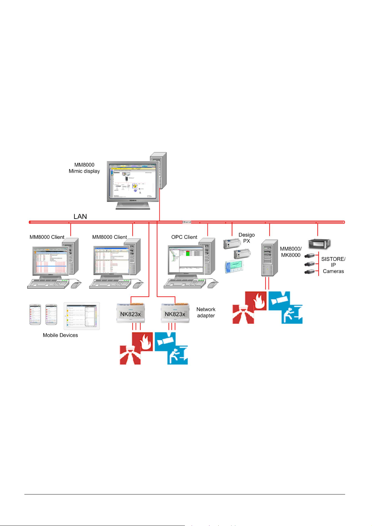
· Small/medium configuration:
In this configuration, a main station provides for the server functions, including local
and networked (NK82xx) communication. Then, one or more stations running the
client are connected to the server (See Fig. 3 and Fig. 4.). Each client machine
may contain any subset of the applications. It is possible to have stations running
only the basic modules – for example, those devoted to surveillance only – and
stations with a more c om plete set of tools, such as the Plant and History browser s
used by engineers or supervisors. In addition, web stations and m obile devices are
also supported for local or remote access to the event list. A mimic displ ay client
(MM8000 Client Station with Plant Browser in full screen mode) can be used to
provide a full screen graphic of system status.
Fig. 3 MM8000/MK8000 small/medium configuration TBS
14
Building Technologies 049_DMS_DMS8000_Application_Specification_Planning_MP4.81_A6V10063710_a_en.doc
CPS Fire Safety 09.2016
Management level configurations
Fig. 4 MM8000/MK8000 + SiPass small/medium distributed configuration
Note: MM8000/MK8000 and SiPass servers may reside separately. This is recom -
mended for l arge/high connectivity configurations.
For technical det ails, please contact customer support.
https://intranet1.siemens.com/ org/bt/en/business/support/Pages/csc-fs.aspx
Building Technologies 049_DMS_DMS8000_Application_Specification_Planning_MP4.81_A6V10063710_a_en.doc
CPS Fire Safety 09.2016
15
Management level configurations
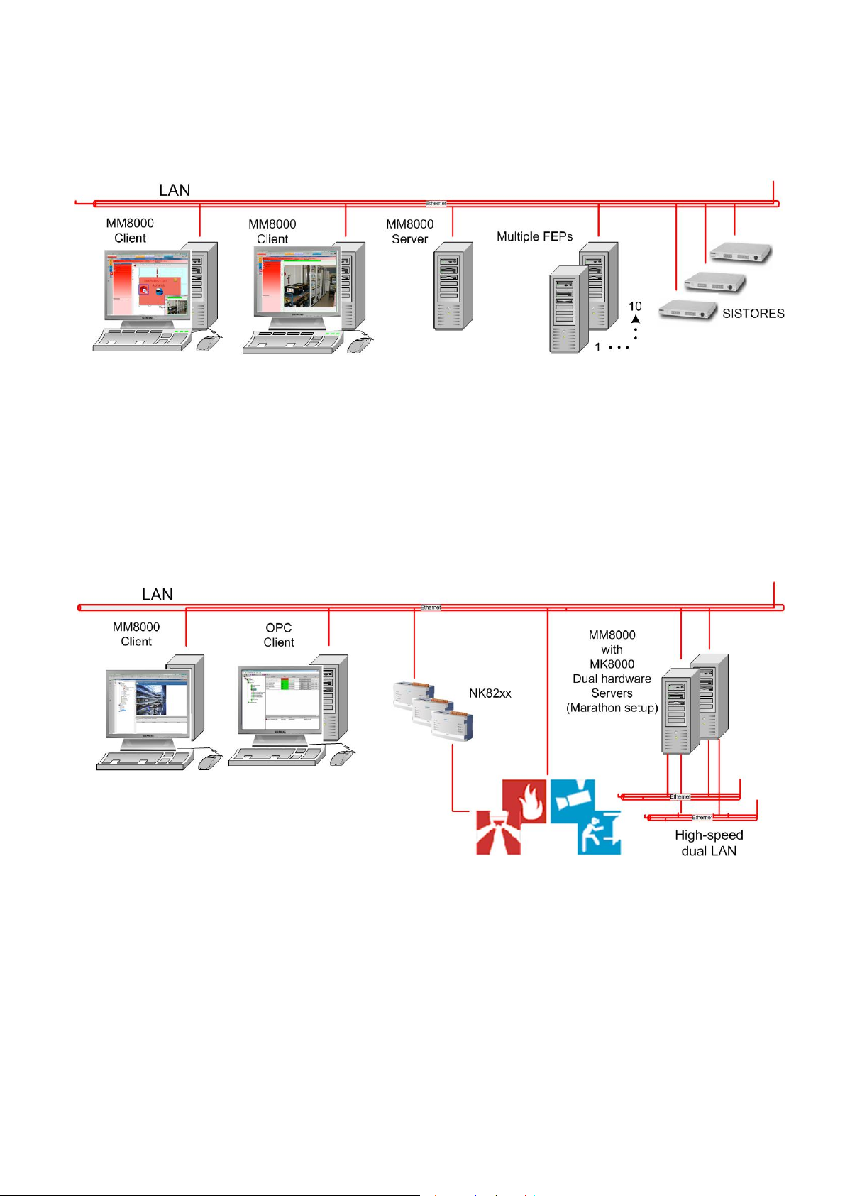
· Large/high connectivity configuration:
Fig. 5 MM8000/MK8000 with multiple FEPs f or communication load distribution
In this confi guration, the server layer and the communication layer are installed on
separate machines. One or more front-end machines can be installed for a large
connectivity over LAN for load distribution.
· Fault-toler ant hard ware configuration:
For maximum reliability, the server hardware can be doubled and managed with
Marathon ev erRun™ FT software. This ensures zero downtime. In this solution, the
field connectivity is based on a LAN connection.
Fig. 6 MM8000/MK8000 fault-tolerant redundant configuration with dual servers
Note: For technical details regarding this redundancy configuration solution, please
contact customer support.
https://intranet1.siemens.com/ org/bt/en/business/support/Pages/csc-fs.aspx
16
Building Technologies 049_DMS_DMS8000_Application_Specification_Planning_MP4.81_A6V10063710_a_en.doc
CPS Fire Safety 09.2016

Management level configurations
· Multiple server configurat ion:
For high reliability, the server is replicated, and a manual server switch functi onality
is available on the client station(s) in the event that a backup solution is desired.
If the server fails, the client can switch to another server configured for the same
project thus ensuring minimum connectivity interruption.
Up to four servers can be configured.
Fig. 7 Multiple server distributed configuration
Note: Clients can connect to only one server at a time.
· Virtual server configuration:
MM8000 offers support for virtual machine solutions. One or more MM8000 virtual
clients/servers can run in the following virtualization environments:
- VMware workstation
- VMware v Sphere Hypervisor (ESXi)
- Windows Hyper-V
Fig. 8 Virtual server distributed configuration
Building Technologies 049_DMS_DMS8000_Application_Specification_Planning_MP4.81_A6V10063710_a_en.doc
CPS Fire Safety 09.2016
17
Management level configurations
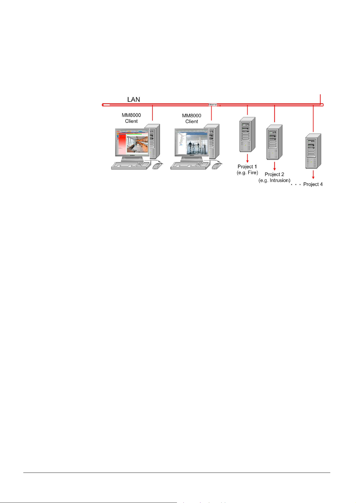
· Multiple projects on separate servers configuration:
MM8000 supports mul tiple projects residing on separate serv ers. These servers
are available to client stations via a manual server switch functionality.
This provides the ability to switch one or more clients from, for example, an intrusion to a fire network.
Up to four servers are configurable.
Fig. 9 Multiple projects distributed on separate servers
18
Building Technologies 049_DMS_DMS8000_Application_Specification_Planning_MP4.81_A6V10063710_a_en.doc
CPS Fire Safety 09.2016

2.2 Support of mobile devices
Mobile devices (smartphones and tablets) are supported in MM8000 by the DMS8000
Web Services and the MM8000 Alarms app.
The DMS8000 Web Services interface (REST Web API) enables any client supporting
this Representational State Transfer (REST) Appl ication Program Interface (API) to
handle MM8000 ev ents.
The MM8000 Alarms app is based on this interface and lets an operator view and
handle events with Acknowledge and Reset commands. Once a MM8000 Al arms app
user is authenticated, the server sends to the MM8000 Alarms app only the inform ation and commands that t he user is authorized to see and execute based on his/her
security profil e.
2.2.1 National standards, regulations and legislation
Siemens products are developed and produced in compliance with the relevant European and international safety standards. Should addit ional national or local safety
standards or legislation concerning the planning, assembly, installation, operation or
disposal of the product apply at the place of operation, then these must also be taken
into account together with the safety regulations in the product documentation.
Management level configurations
WARNING
It is in the responsibility of the Regional Count ries (RC’s) to carefully check
whether the use of the MM8000 Alarms app (or externally developed app’s) for
handling events from MM8000 is allowed by national or local safety standards or
codes of practice.
If local law or codes of practice do not allow controlling events from mobile devices,
the DMS8000 Web Services can be set to view only mode.
® For det ails about how to set the DMS8000 Web Services in view only mode, see
the MM8000 ICC (A6V10062413). To l earn how to obtain this document, see the
Documentation resource information sect ion on p. 5.
MM8000 Server requi rements
The following is required on the MM8000 Server PC for supporting mobile devices:
- Internet Inf ormation Services (IIS)
- MM8000 installed with the setup type Stand-alone (MM8000) and the option
Web Services enabled
- MM8000 license including the Base Station Option Web Services
- The Web Services are enabled in the configurati on on the Station Node
- Internet connection or connection to a WLAN
® For det ails about IIS settings MM8000 installation and configuration, see the
MM8000 ICC (A6V10062413). T o learn how to obtain this document, see the
Documentation resource information sect ion on p. 5.
Mobile devices requirements
The following is required on the mobile device:
- Sm artphone or tablet with Android operating system version 4.0 or later
- i Phone or iPad with iOS version 6 or later
- MM8000 Alarms app installed
Building Technologies 049_DMS_DMS8000_Application_Specification_Planning_MP4.81_A6V10063710_a_en.doc
CPS Fire Safety 09.2016
19
Management level configurations
® For details about the Mobile device requirement s, Web Station Browser requi re-
ments and how to get and install the MM8000 Alarms app see the MM8000 Alarms
Quick S tart Guide (A6V10425977). To learn how to obtain this document, see the
Documentation resource information sect ion on p. 5.
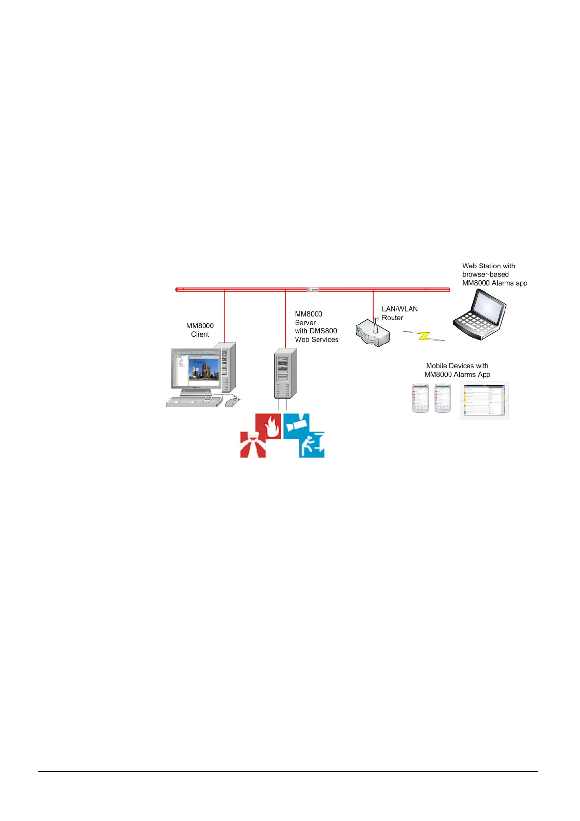
2.2.2 Mobile devices connected via WLAN wireless network
WLAN connections are mainly used in in-house applications because they are limited
in range.
In this type of application the MM8000 Server needs to be connected to a WLAN
router. Activating the WLAN encryption on the router protects the WLAN wireless network against unauthorized use. We recommend using the WPA encryption, which
provides the highest level of security. The level of security can be further increased by
limiting the access to the router to known devices only.
On the mobile devices, the WLAN must be enabled and the mobile device needs to be
connected to the WLAN wireless network.
Fig. 10 DMS8000 Web Services – W LAN connection
20
Building Technologies 049_DMS_DMS8000_Application_Specification_Planning_MP4.81_A6V10063710_a_en.doc
CPS Fire Safety 09.2016
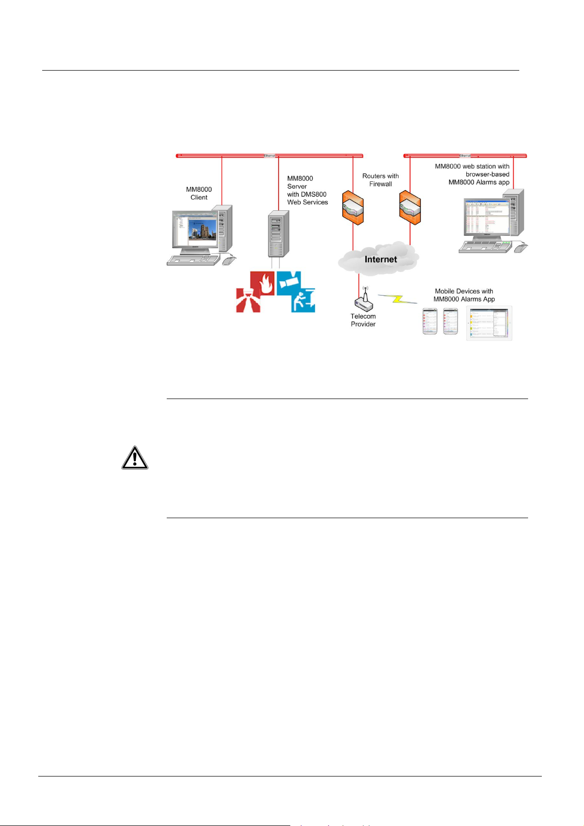
2.2.3 Mobile devices connected via Internet
The following picture shows a configuration where the MM8000 server is connected
through a router with firewall to the internet, which is configured with a fixed public IP
address. The mobile devices connect over the mobile telecommunication network to
the internet.
Management level configurations
Fig. 11 DMS8000 W eb Services – Internet connection
WARNING
Note that that handling safety and security events from remote over the Internet
might be risky and not be al lowed by the company’s security policy, local law or
code of practice.
Consider to configure the Web Services in view only mode and/or setup a Virtual
Private Network (VPN) connection between the router and the mobile devices.
In addition, we recommend using the IIS Client Certificate Mapping Authentication
method in order to ensure that only mobile devices with a valid certificate are able
to connect to the DMS8000 Web Services.
Building Technologies 049_DMS_DMS8000_Application_Specification_Planning_MP4.81_A6V10063710_a_en.doc
CPS Fire Safety 09.2016
21
Management level configurations
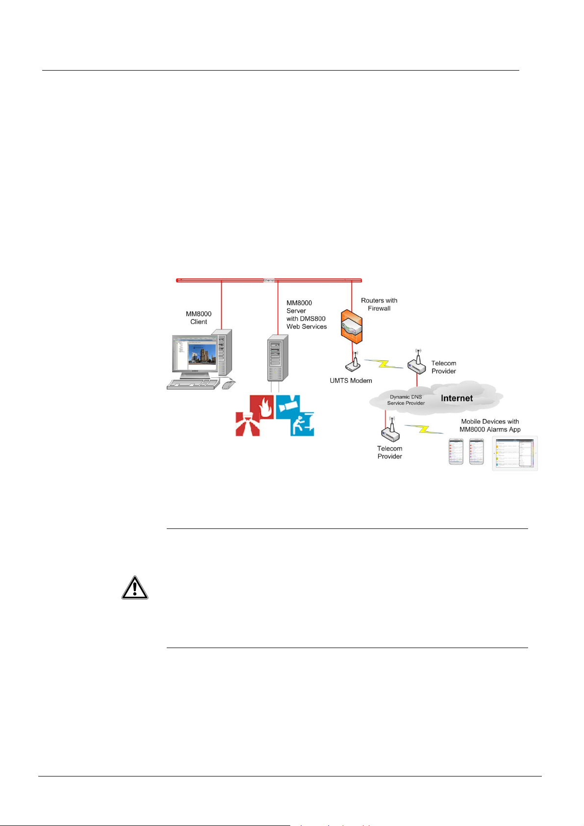
2.2.4 Mobile devices connected via UMTS
The following picture shows a configuration where the MM8000 server is connected
through a router with firewall and UMTS modem over the mobile telecommunication
network to the internet.
The mobile devices connect over the mobile telecommunication network to the internet.
Whenever the router is connected to the Internet via mobile telecommunications, it is
assigned a dynamic IP address. For accessing the DMS8000 Web Services with the
mobile devices, the router must be accessible from the Internet under a fixed domain
name. To specify dom ain nam e, user name, and password, you must register with a
dynamic DNS provi der.
The router m ust be able to support the dynamic DNS. The dynamic DNS provider,
Domain name, User name, and Password fields must be configured in the router using
the registration information from the dynamic DNS provider.
Fig. 12 DMS8000 W eb Services – UMTS connec tion
WARNING
Note that that handling safety and security events from remote over the Internet
might be risky and not be al lowed by the company’s security policy, local law or
code of practice.
Consider to configure the Web Services in view only mode and/or setup a Virtual
Private Network (VPN) connection between the router and the mobile devices.
In addition, we recommend using the IIS Client Certificate Mapping Authentication
method in order to ensure that only mobile devices with a valid certificate are able
to connect to the DMS8000 Web Services.
22
Building Technologies 049_DMS_DMS8000_Application_Specification_Planning_MP4.81_A6V10063710_a_en.doc
CPS Fire Safety 09.2016

2.3 NK8000 network configurations
NK8000 safety and security networks are supported by MM8000 and MK8000 M P4.81
in the configurat ions described in section 2. 1 (up to four hosts). Additional configuration examples are ill ustrated in this section.
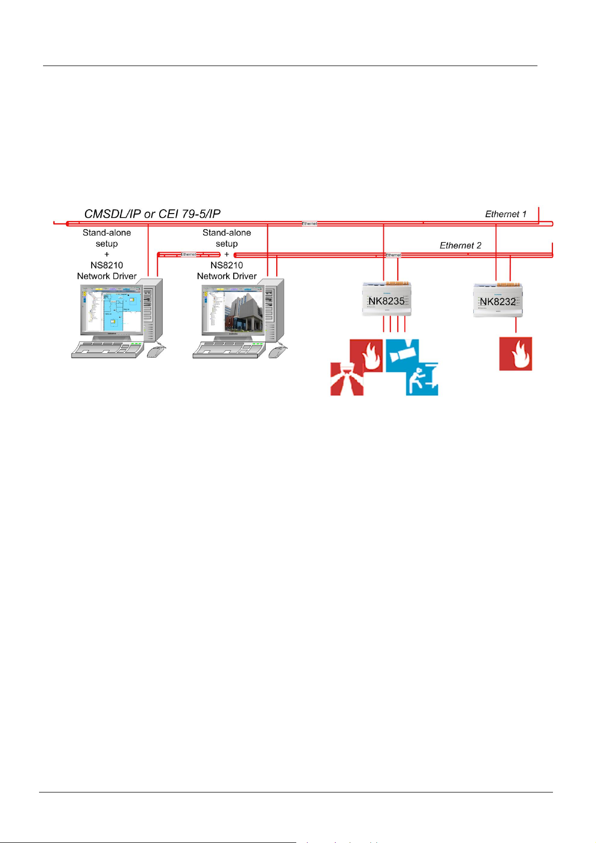
2.3.1 DMS8000 Multiple host configuration – CMSDL/IP
Characteristics:
- Comm unication layer equipped with NS8210 Network driver, CMSDL/IP protocol
- Up to f our hosts
Management level configurations
Fig. 13 NK8000 CMSDL/IP m ultiple host configurati on example
2.3.2 DMS8000 multiple host configuration – BACnet/IP
Characteristics:
- Comm unication layer equipped with NS8011 BACnet Network Driver
® See section 3.2.13 for subsystems supported.
- Up to f our DMS8000 hosts
- Pref erred solution if system extensions with FS20 Sinteso/FS720 Cerberus
PRO and/or DESIGO PX are expected
- Pref erred solution if only NK823xs are used (network-wide interactions)
Fig. 14 NK823x DMS8000 BA Cnet m ultiple host configurati on ex ample
Note: CS11 AlgoRex connectivity direct or via Cerloop.
Building Technologies 049_DMS_DMS8000_Application_Specification_Planning_MP4.81_A6V10063710_a_en.doc
CPS Fire Safety 09.2016
23
Management level configurations
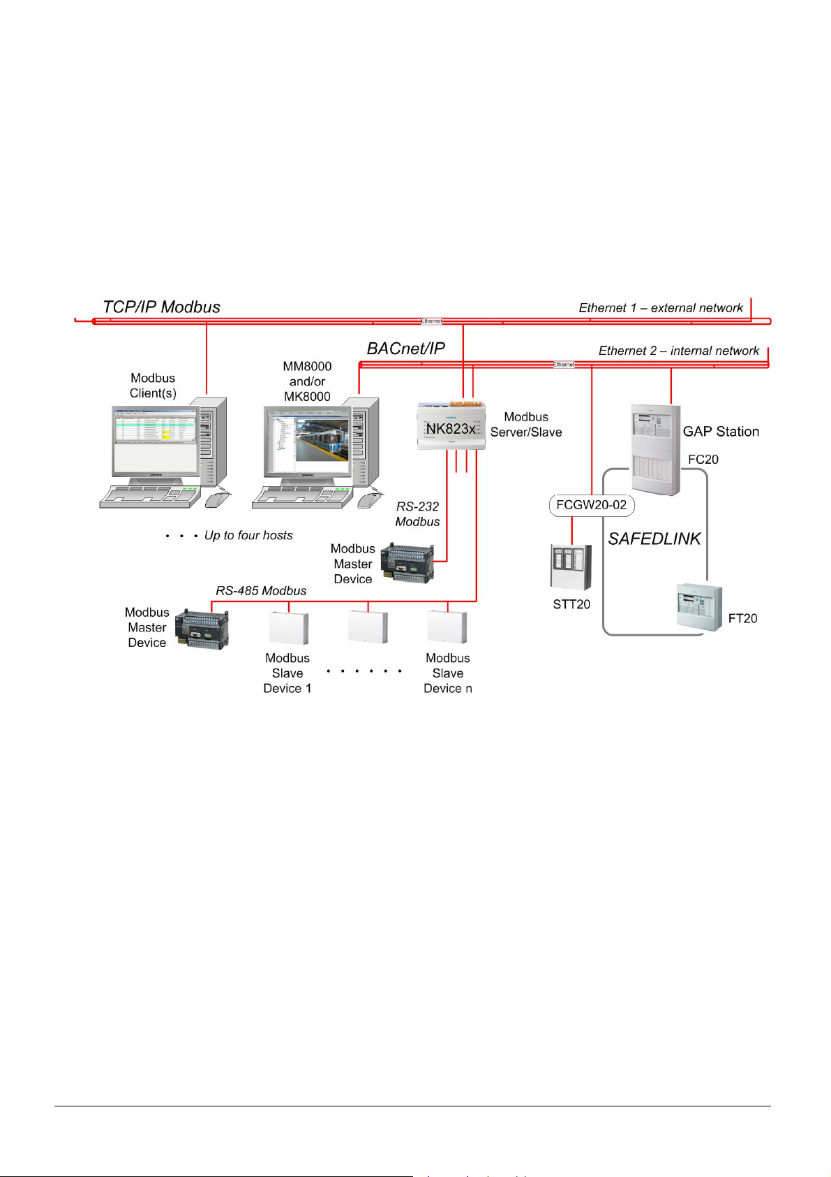
2.3.3 Modbus Gateway for fire applications and network separation
Characteristics:
- Comm unication layer equipped with NS8210 Network driver, CMSDL/IP protocol or NS8011 BACnet Network driver, BACnet/IP protocol for DMS8000
- Up to four hosts (any combination MM8000/MK8000/TCP/I P Modbus client)
- Sim ultaneous support of 3rd party TCP/IP Modbus and serial Modbus (up to four
total connections)
- Limit two Modbus serial devices
- Modbus GW for Sinteso, Cerberus PRO, and STT20 panels routing and firewall
functions across two Ethernet lines
Fig. 15 NK823x as Modbus Gateway configuration example
24
Building Technologies 049_DMS_DMS8000_Application_Specification_Planning_MP4.81_A6V10063710_a_en.doc
CPS Fire Safety 09.2016
Management level configurations
2.3.4 DMS8000 multiple or single host – network redundancy with dual LAN
Characteristics:
- Comm unication layer equipped with NS8210 Network driver, CMSDL/IP or CEI
79-5 protocol,
- Up to f our hosts (limit two hosts for CEI)
- Dual Ethernet connections f or network redundancy
If the primary NK823x Ethernet connection goes down, the NK823x can communicate with the management station(s) via the secondary Ethernet connec tion.
Fig. 16 NK823x redundant network configuration example
Building Technologies 049_DMS_DMS8000_Application_Specification_Planning_MP4.81_A6V10063710_a_en.doc
CPS Fire Safety 09.2016
25
Management level configurations
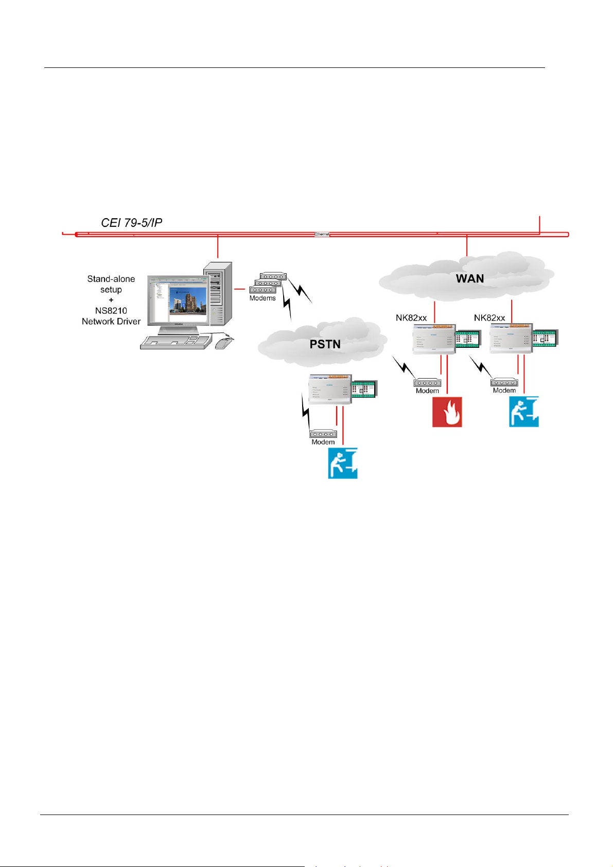
2.3.5 DMS8000 – support of dial-up connections
Characteristics:
- Comm unication layer equipped with NS8210 Network driver and modem(s),
CEI 79-5/IP prot ocol
- NK82x x dial-ups as primary (no Ethernet connection) or secondary (in case
network is down) via PSTN
- Encryption supported
- Up to two CEI hosts (NK823x only)
Note: Dial-ups not supported on 2nd host
Fig. 17 NK8000 dial-up configuration example
26
Building Technologies 049_DMS_DMS8000_Application_Specification_Planning_MP4.81_A6V10063710_a_en.doc
CPS Fire Safety 09.2016

3 Automation level configurations
3.1 Configurations supported by MM8000/MK8000
The MM8000/MK8000 MP4.81 support the following:
Automation level configuration types
- Direct RS-232
- Cerloop
- CDI-Net
- NK8000
- Direct LAN
- FCnet (SAFEDLINK)
Network components
- NK82xx
- MK7022
- GW-21, GW20
Automation level configurations
Control units
Note: For control unit versions, see MM8000 MP4.81 Release Notes (A6V10062509).
To learn how to obtain this document, see the Documentation resource inform ation
section on page 5.
Fire detection systems:
- CS11 AlgoRex
- FC700A
- CS1115/FC330A
- CZ10
- XLS
- FS20 Sinteso™
- FS720 Cerberus© PRO
- STT11 (Système de Télécommande et Télésignali sation)
- STT20/STT2410
- SIGMASYS/D100
Intrusion detection systems:
- SPC 4000/5000/6000
- SI410/420
- CS4
- CS440
- CZ12
- CS6 Guarto
Gas detection systems:
- CC60
Building Technologies 049_DMS_DMS8000_Application_Specification_Planning_MP4.81_A6V10063710_a_en.doc
CPS Fire Safety 09.2016
27

Automation level configurations
Video systems:
Access control:
Building aut om ation:
- SIMATRIX, SIMATRIX NEO video crossbars
- SISTORE AX, CX, MX (including NVS*), MXpro, SX, Vectis HX and iX
NVR/NVS
- TELSCAN
- IP cameras (fixed) equipped wit h:
- CCIS1337-LP
- CFVA-IP
- CVVA-IP
*Network Video Soft ware
- SiPass Integrated Access Control System
- CerPass CC30 (connected via SiPass)
- DESIGO PX
‡
General autom ation and I/O systems:
- SIMATIC S7
- MF7033/MM7033 digital PLC unit
- DF8000 digital I/O systems
Remote notification:
- ESPA Paging System
‡
- Analog modem for dial-up connections
3rd party systems:
- A number of 3rd party systems are supported via NK82xx or MM8000 drivers.
® For details, see section 3.4.
Section 3.2 details the configuration types supported by MM8000 and MK8000.
Note: Combinations of automation level configurations are also supported.
® For network connectivity options, see Appendix A.
‡
MM8000 only
28
Building Technologies 049_DMS_DMS8000_Application_Specification_Planning_MP4.81_A6V10063710_a_en.doc
CPS Fire Safety 09.2016
3.2 Configuration types
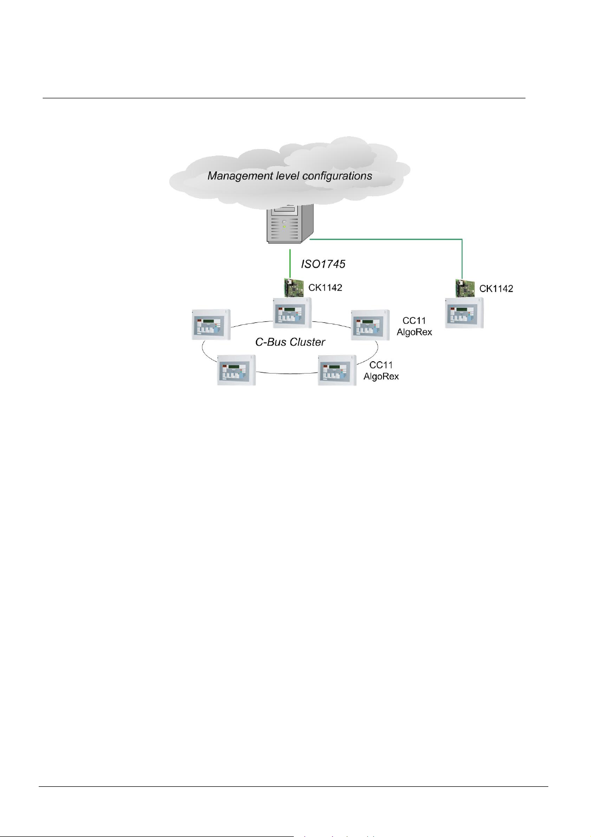
3.2.1 ISO1745 direct configuration
Automation level configurations
Fig. 18 ISO1745 direct configuration example
System architecture
This configuration allows for integration of CS11 AlgoRex (or FC700A) fire panels.
The CK1142/43 (or FG700A) provides the liaison t o MM8000/MK8000.
Communication/connection
The upstream si de of the gat eway (CK1142/43 or FG700A) is connect ed to the DMS
via serial line. The downstream side of the gateway is connected to one (or more)
CS11 AlgoRex (or FC700A) fire panels via the proprietary C-Bus.
Building Technologies 049_DMS_DMS8000_Application_Specification_Planning_MP4.81_A6V10063710_a_en.doc
CPS Fire Safety 09.2016
29
 Loading...