

Siemens NIM-1W Installation Instructions Manual
Installation Instructions
Model NIM-1W Network Interface Module
NETWORK INTERFACE APPLICATIONS
OPERATION
The Model NIM-1W from Siemens Industry, Inc.,
provides a new communication path for the following
uses:
• as an XNET networking interface
• as an HNET connection to NCC WAN
• as a connection to Foreign Systems
• as a connection to Air Sampling detectors
When used as an XNET networking interface the
NIM-1W allows for the connection of up to 63 MXL
and/or XLS Systems. On an XNET network the NIM1W also supports monitor and control functionality by
Siemens products, such as NCC and Desigo CC.
Output logic between MXL panels is done using
CSG-M programming. CSG-M versions 6.01 and
higher include options for networked MXL Systems.
Each MXL System is assigned a panel number. This
panel number allows interactive programming between panels using CSG-M.
The NIM-1W supports both Style 4 and Style 7
connection. In the event of an NIM-1W communication failure, each MXL System continues to operate
as a standalone panel.
The NIM-1W can also be configured as an RS-485
two wire interface to foreign systems. NIM-1W
RS485 only supports Style 4 wiring. Via the add-on
modem card NIM-1M, NIM-1W can also be configured for modem connection. This operation is called
FSI (Foreign System Interface). The FSI responds
to a protocol and gathers information about the MXL
status. The interface supports both single MXL
Systems and networked systems. Typical use of
this interface is between the MXL and building
management systems.
Use the CSG-M to enable the functions accessed
by the foreign system. If the foreign system is UL
864 listed with the MXL, the interface can also be
enabled to support control of the MXL including the
commands to acknowledge, silence, and reset.
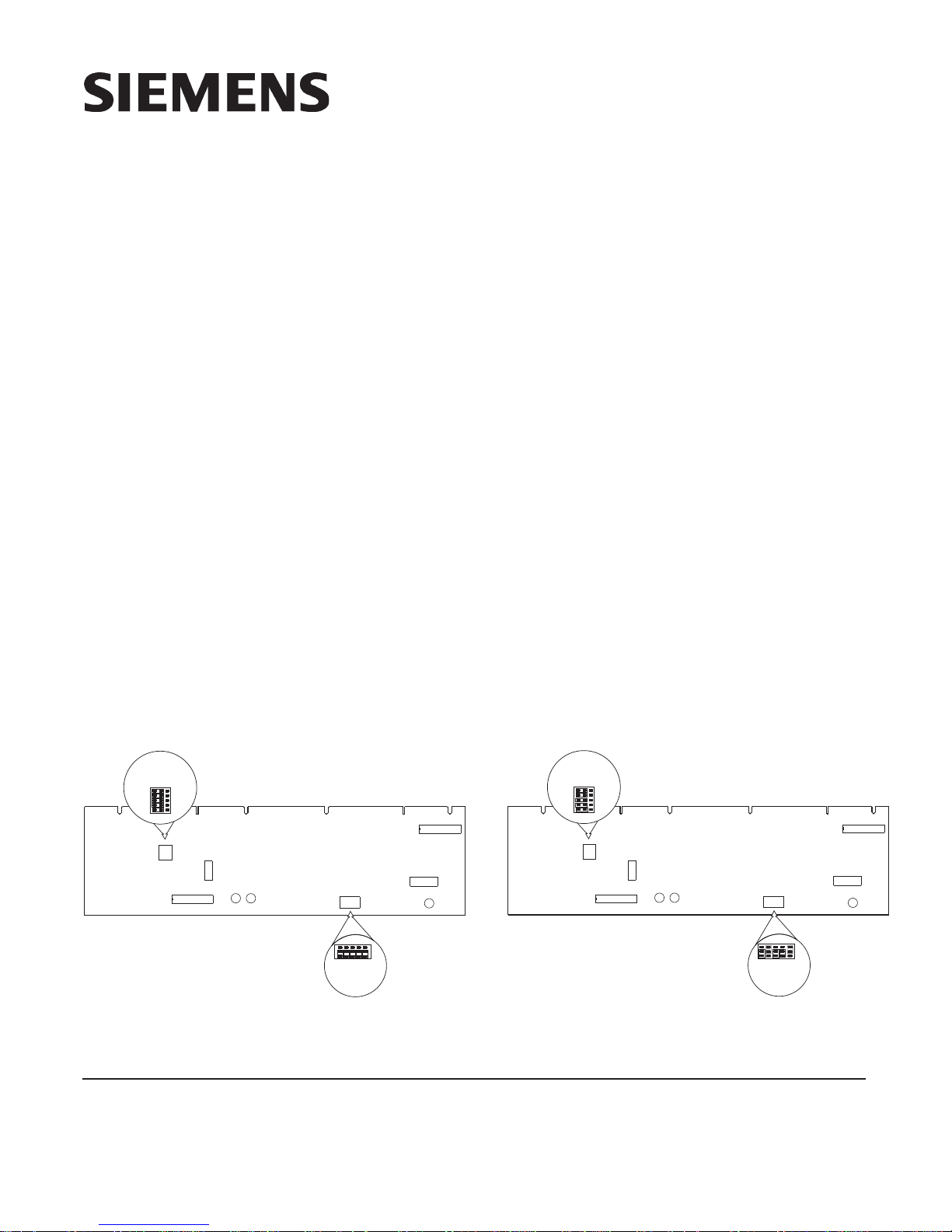
INSTALLJUMPER
PLUGS IN ORIENTATION
AS SHOWN. POSITION
M
SHOWN SELECTED.
MW
JP4
1
13
MW
JP4
3
15
SW1
1
87654321
JP2
D4 D5
ANY
TRBL
NIM-1W
ANY
ENABLE
P6
3
+
–
1
INSTALLJUMPER PLUGS IN
ORIENTATIONAS SHOWN
FOR RS485 WIRING.
POSITION SHOWN
SELECTED.
Figure 1
NIM-1W Module Board (RS485 setting)
Siemens Industry, Inc.
Building Technologies Division
Florham Park, NJ
P/N 315-099165-10
INSTALLJUMPER
PLUGS IN ORIENTATION
AS SHOWN. POSITION
M
SHOWN SELECTED.
MW
87654321
SW2
JP1
15
W
X
13
W
X
P6
X
D8
XMIT
JP4
1
13
MW
JP4
3
15
SW1
1
87654321
D4 D5
ANY
TRBL
NIM-1W
ANY
ENABLE
P6
3
15
+
W
–
X
13
1
P6
INSTALLJUMPER PLUGS IN
ORIENTATIONAS SHOWN
FOR MODEM.
W
X
JP2
87654321
SW2
JP1
D8
XMIT
Figure 2
NIM-1W Module Board (modem setting)
Siemens Canada Limited
Building Technologies Division
2 Kenview Boulevard
Brampton, Ontario L6T 5E4 Canada

TABLE 1
NETWORK ADDRESS PROGRAMMING (SW1)
ADDR
000 ILLEGAL 064 OXOOOOOO 128 XOOOOOOO 192 XXOOOOOO
001 ILLEGAL 065 OXOOOOO X 129 XOOOOOOX 193 XXOOOOOX
002 ILLEGAL 066 OXOOOOXO 130 XOOOOOXO 194 XXOOOOXO
003
004
005
006
007
008
009
010
011
012
013
014
015
016
017
018
019
020
021
022
023
024
025
026
027
028
029
030
031
032
033
034
035
036
037
038
039
040
041
042
043
044
045
046
047
048
049
050
051
052
053
054
055
056 OOXXXOOO 120 OXXXXOOO 184 XOXXXOOO 248 ILLEGAL
057 OOXXXOOX 121 OXXXXOOX 185 XOXXXOOX 249 ILLEGAL
058 OOXXXOXO 122 OXXXXOXO 186 XOXXXOXO 250 ILLEGAL
059 OOXXXOXX 123 OXXXXOXX 187 XOXXXOXX 251 ILLEGAL
060 OOXXXXOO 124 OXXXXXOO 188 XOXXXXOO 252 ILLEGAL
061 OOXXXXOX 125 OXXXXXOX 189 XOXXXXOX 253 ILLEGAL
062 OOXXXXXO 126 OXXXXXXO 190 XOXXXXXO 254 ILLEGAL
063 OOXXXXXX 127 OXXXXXXX 191 XOXXXXXX 255 ILLEGAL
87654321
OOOOOOXX
OOOOOXOO
OOOOOXOX
OOOOOXXO
OOOOOXXX
OOOOXOOO
OOOOXOOX
OOOOXOXO
OOOOXOXX
OOOOXXOO
OOOOXXOX
OOOOXXXO
OOOOXXXX
OOOXOOOO
OOOXOOOX
OOOXOOXO
OOOXOOXX
OOOXOXOO
OOOXOXOX
OOOXOXXO
OOOXOXXX
OOOXXOOO
OOOXXOOX
OOOXXOXO
OOOXXOXX
OOOXXXOO
OOOXXXOX
OOOXXXXO
OOOXXXXX
OOXOOOOO
OOXOOOOX
OOXOOOXO
OOXOOOXX
OOXOOXOO
OOXOOXOX
OOXOOXXO
OOXOOXXX
OOXOXOOO
OOXOXOOX
OOXOXOXO
OOXOXOXX
OOXOXXOO
OOXOXXOX
OOXOXXXO
OOXOXXXX
OOXXOOOO
OOXXOOOX
OOXXOOXO
OOXXOOXX
OOXXOXOO
OOXXOXOX
OOXXOXXO
OOXXOXXX
ADDR
067
068
069
070
071
072
073
074
075
076
077
078
079
080
081
082
083
084
085
086
087
088
089
090
091
092
093
094
095
096
097
098
099
100
101
102
103
104
105
106
107
108
109
110
111
112
113
114
115
116
117
118
119
87654321
OXOOOOXX
OXOOOXOO
OXOOOXOX
OXOOOXXO
OXOOOXXX
OXOOXOOO
OXOOXOOX
OXOOXOXO
OXOOXOXX
OXOOXXOO
OXOOXXOX
OXOOXXXO
OXOOXXXX
OXOXOOOO
OXOXOOOX
OXOXOOXO
OXOXOOXX
OXOXOXOO
OXOXOXOX
OXOXOXXO
OXOXOXXX
OXOXXOOO
OXOXXOOX
OXOXXOXO
OXOXXOXX
OXOXXXOO
OXOXXXOX
OXOXXXXO
OXOXXXXX
OXXOOOOO
OXXOOOOX
OXXOOOXO
OXXOOOXX
OXXOOXOO
OXXOOXOX
OXXOOXXO
OXXOOXXX
OXXOXOOO
OXXOXOOX
OXXOXOXO
OXXOXOXX
OXXOXXOO
OXXOXXOX
OXXOXXXO
OXXOXXXX
OXXXOOOO
OXXXOOOX
OXXXOOXO
OXXXOOXX
OXXXOXOO
OXXXOXOX
OXXXOXXO
OXXXOXXX
ADDR
131
132
133
134
135
136
137
138
139
140
141
142
143
144
145
146
147
148
149
150
151
152
153
154
155
156
157
158
159
160
161
162
163
164
165
166
167
168
169
170
171
172
173
174
175
176
177
178
179
180
181
182
183
87654321
XOOOOOXX
XOOOOXOO
XOOOOXOX
XOOOOXXO
XOOOOXXX
XOOOXOOO
XOOOXOOX
XOOOXOXO
XOOOXOXX
XOOOXXOO
XOOOXXOX
XOOOXXXO
XOOOXXXX
XOOXOOOO
XOOXOOOX
XOOXOOXO
XOOXOOXX
XOOXOXOO
XOOXOXOX
XOOXOXXO
XOOXOXXX
XOOXXOOO
XOOXXOOX
XOOXXOXO
XOOXXOXX
XOOXXXOO
XOOXXXOX
XOOXXXXO
XOOXXXXX
XOXOOOOO
XOXOOOOX
XOXOOOXO
XOXOOOXX
XOXOOXOO
XOXOOXOX
XOXOOXXO
XOXOOXXX
XOXOXOOO
XOXOXOOX
XOXOXOXO
XOXOXOXX
XOXOXXOO
XOXOXXOX
XOXOXXXO
XOXOXXXX
XOXXOOOO
XOXXOOOX
XOXXOOXO
XOXXOOXX
XOXXOXOO
XOXXOXOX
XOXXOXXO
XOXXOXXX
ADDR
195
196
197
198
199
200
201
202
203
204
205
206
207
208
209
210
211
212
213
214
215
216
217
218
219
220
221
222
223
224
225
226
227
228
229
230
231
232
233
234
235
236
237
238
239
240
241
242
243
244
245
246
247
87654321
XXOOOOXX
XXOOOXOO
XXOOOXOX
XXOOOXXO
XXOOOXXX
XXOOXOOO
XXOOXOOX
XXOOXOXO
XXOOXOXX
XXOOXXOO
XXOOXXOX
XXOOXXXO
XXOOXXXX
XXOXOOOO
XXOXOOOX
XXOXOOXO
XXOXOOXX
XXOXOXOO
XXOXOXOX
XXOXOXXO
XXOXOXXX
XXOXXOOO
XXOXXOOX
XXOXXOXO
XXOXXOXX
XXOXXXOO
XXOXXXOX
XXOXXXXO
XXOXXXXX
XXXOOOOO
XXXOOOOX
XXXOOOXO
XXXOOOXX
XXXOOXOO
XXXOOXOX
XXXOOXXO
XXXOOXXX
XXXOXOOO
XXXOXOOX
XXXOXOXO
XXXOXOXX
XXXOXXOO
XXXOXXOX
XXXOXXXO
XXXOXXXX
XXXXOOOO
XXXXOOOX
XXXXOOXO
XXXXOOXX
XXXXOXOO
XXXXOXOX
XXXXOXXO
XXXXOXXX
O = OPEN (or OFF) X = CLOSED ( or ON)
2
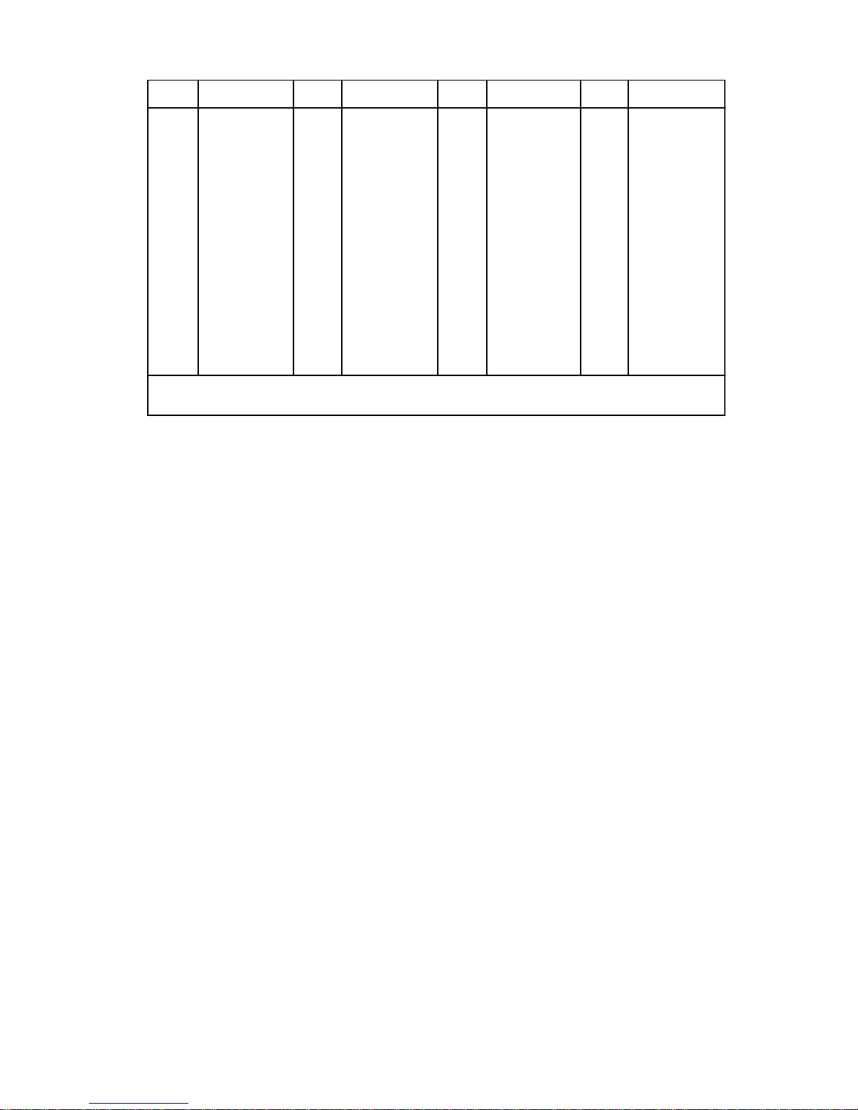
TABLE 2
PANEL NUMBER PROGRAMMING (SW2)
ADDR 8 7 6 5 4 3 2 1 ADDR 8 7 6 5 4 3 2 1 ADDR 8 7 6 5 4 3 2 1 ADDR 8 7 6 5 4 3 2 1
000
001
002
003
004
005
006
007
008
009
010
011
012
013
014
015
---
ROOOOOOO
SOOOOOOX
SOOOOOXO
SOOOOOXX
SOOOOXOO
SOOOOXOX
SOOOOXXO
SOOOOXXX
SOOOXOOO
SOOOXOOX
SOOOXOXO
SOOOXOXX
SOOOXXOO
SOOOXXOX
SOOOXXXO
SOOOXXXX
---------------
016
017
018
019
020
021
022
023
024
025
026
027
028
029
030
031
---
SOOXOOOO
SOOXOOOX
SOOXOOXO
SOOXOOXX
SOOXOXOO
SOOXOXOX
SOOXOXXO
SOOXOXXX
SOOXXOOO
SOOXXOOX
SOOXXOXO
SOOXXOXX
SOOXXXOO
SOOXXXOX
SOOXXXXO
SOOXXXXX
---------------
032
033
034
035
036
037
038
039
040
041
042
043
044
045
046
047
---
SOXOOOOO
SOXOOOOX
SOXOOOXO
SOXOOOXX
SOXOOXOO
SOXOOXOX
SOXOOXXO
SOXOOXXX
SOXOXOOO
SOXOXOOX
SOXOXOXO
SOXOXOXX
SOXOXXOO
SOXOXXOX
SOXOXXXO
SOXOXXXX
--------------
048
049
050
051
052
053
054
055
056
057
058
059
060
061
062
063
064
SOXXOOOO
SOXXOOOX
SOXXOOXO
SOXXOOXX
SOXXOXOO
SOXXOXOX
SOXXOXXO
SOXXOXXX
SOXXXOOO
SOXXXOOX
SOXXXOXO
SOXXXOXX
SOXXXXOO
SOXXXXOX
SOXXXXXO
SOXXXXXX
SXOOOOOO
S = Closed selects Style 7
S = Open selects Style 4
O = Open or OFF
X = Closed or ON
NOTE:
To open a dipswitch, press down on the side of the dipswitch marked OPEN.
To close a dipswitch, press down on the side of the dipswitch opposite the side marked OPEN.
To open a slide switch, push the slide to the side opposite the side marked ON.
To close a slide switch, push the slide to the side marked ON.
The NIM-1W also provides for the connection of up to
31 Air Sampling detectors. The MXL supports individual programming and monitoring of the Air Sampling devices. Each detector can be uniquely programmed from the MKB menu or by using CSG-M. All
three alarm levels (PreAlarm 1, PreAlarm 2, and
Alarm) are supported.
NOTE: When the NIM-1W is configured as an Air
Sampling interface, it cannot support either
MXL networking or the FSI. If these functions
are required, additional NIM-1Ws must be
used.
For additional information on the MXL/MXLV System,
refer to the MXL/MXLV Manual, P/N 315-092036.
INSTALLATION
Remove all system power before installation,
first battery and then AC. (To power up, con-
nect the AC first, then the battery.)
The NIM-1W installs into the MXL optional MOM-4/2
card cage where it occupies one full width slot. The
NIM-1W can be installed in either of the full slots of the
MOM-4/2.
nected to TB3 or TB4 of the MOM-4/2.
The slot determines if the wiring is con-
R = Closed selects AnaLASER
R = Open selects FSI
Setting the Switches
Set all switches, configuration jumpers, and
connection cables before installing the NIM-1W
into the MOM-4.
Use switch SW1 to set the MXL network address. Set
this switch according to the address where the NIM-1W
is installed in the MXL’s network map. Refer to the
CSG-M configuration printout for the address of the
module. See Table 1 for settings.
Use switch SW2 to set either the panel number for
networked systems or to select FSI or Air Sampling
operation. Refer to Table 2 for panel settings, Table 3
for FSI settings, and Table 4 for Air Sampling settings.
1. When installing the NIM-1W in a networked
system, set the panel number to agree with the
panel number for the NIM-1W assigned to the
MXL System in CSG-M.
2. Switch position 8 selects Style 4 or Style 7
operation for the NIM-1W network.
3. Set jumper plugs on JP4 to the "M" position.
4. Set jumper plugs on P6 to the "X" position (Figure
1) if using NIM-1W for RS-485 interface. Set
jumper plugs on P6 as shown in Figure 2 if using
NIM-W for modem interface.
3
 Loading...