

Siemens NIM-1M Installation Instructions Manual
Installation Instructions
Model NIM-1M
Network Interface Modem Module
OPERATION
The Model NIM-1M plug-in modem board from
Siemens Industry, Inc., mounts to and is connected to
the NIM-1W board to provide modem communication
capability for an MXL System XNET network.
The modem transmission line connected to the
NIM-1M can only be Style 4 and can be made using
standard 18 AWG shielded twisted pair or data
grade phone lines.
Note: A pair of NIM-1W / NIM-1M board sets is
referred to as a “bridge” in this document.
INSTALLATION
Remove all system power before installation,
first battery and then AC. To power up, connect AC
first, then the battery.
Setting the Switches
Before mounting the NIM-1M modem module on the
NIM-1W, set all the switches and configuration
jumpers on both modules. Refer to the NIM-1W
Installation Instructions, P/N 315-099165 for information on setting the switches on the NIM-1W.
P2
TIP
1
RING
2
SHIELD*
3
TB1
LOCAL EARTH
GROUND
P1
*TIE SHIELD TO EARTH GROUNDAT ONE END ONLY
JP1
NOTES:
1. "ON" IS WHEN THE JUMPER IS IN THE PROPER POSITION
2. THE CABLE THATCONNECTS THE NIM-1M TO THE NIM-1W
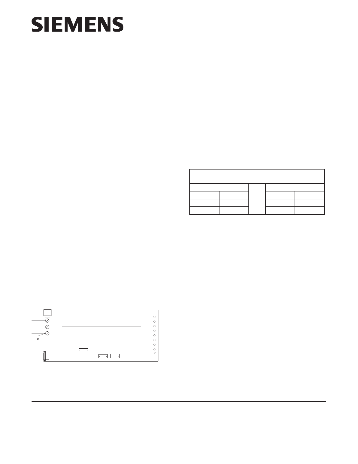
Figure 1
NIM-1M Module Board
NIM-1M
Modem board
JP2
JP3
OVER PLUGS JP1, JP2, OR JP3.
IS ATTACHED TO THE UNDERSIDE OF THE NIM-1M.
RTSRICDRXDTXDDTRDSRCTSPWR
NIM-1M SETTINGS
The NIM-1M has three configuration headers (refer
to Figure 1). The NIM-1Ms are always connected in
board sets, or pairs, with NIM-1Ws to form the
bridge. Designate one board set as NIM-1M LOCAL
and the other as NIM-1M REMOTE. Program the
NIM-1Ms as shown in Table 1.
1ELBAT
sM1-MINEHTGNIMMARGORP
LACOLM1-MINETOMERM1-MIN
1PJ
2PJ
3PJ
NO
NO
FFO
1PJ
2PJ
3PJ
NO
FFO
NO
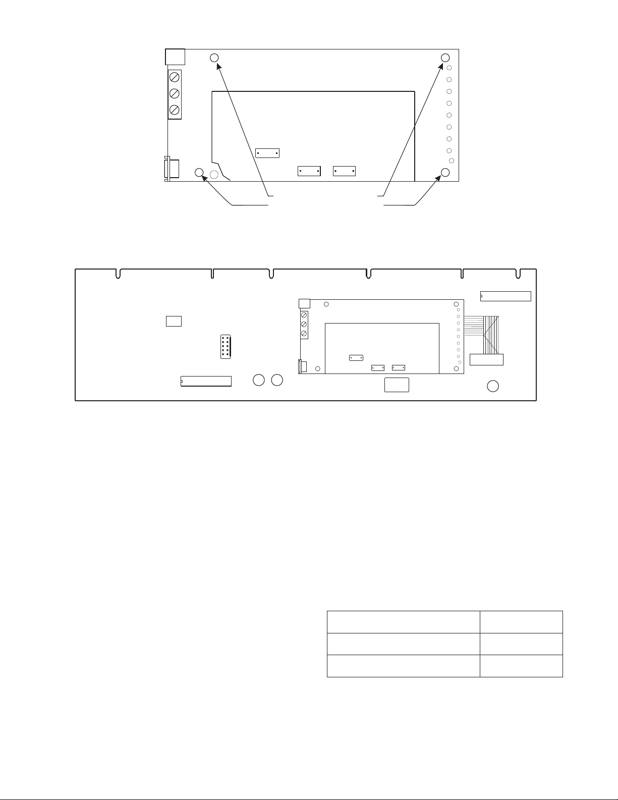
Mounting
The NIM-1M is mounted on the NIM-1W with 4 nylon
spacers.
1. Snap the 4 nylon spacers into place in the holes
on the underside of the NIM-1M board in the
positions indicated in Figure 2.
2. Position the 4 spacers on the NIM-1M over the 4
holes on the component side of the NIM-1W.
Refer to Figure 3 for representative location of
the NIM-1M on the NIM-1W. Press the spacers
firmly into place in the NIM-1W one at a time.
Cable Connections from NIM-1M to NIM-1W
The NIM-1M has a cable attached to the underside
of the board that connects to JP1 of the NIM-1W.
The cable plug is polarized and connects one way
only. Refer to Figure 3 for the location of JP1. Refer to
the NIM-1W installation instructions, P/N 315099106, for installing MXL WAN.
Siemens Industry, Inc.
Building Technologies Division
Florham Park, NJ
P/N 315-099105-6
Siemens Canada Limited
Building Technologies Division
2 Kenview Boulevard
Brampton, Ontario L6T 5E4 Canada
P2
1
2
3
TB1
P1
BOARD
NIM-1M
JP1
JP3
INSERT 4 NYLON SPACERS
IN HOLES
IN POSITIONS INDICATED BY ARROWS
ON UNDERSIDE OF
Figure 2
Installing the Spacers on the NIM-1M Module Board
P2
NIM-1W
MW
JP4
1
87654321
SW1
JP2
12
9
10
D4 D5
ANY
ANY
TRBL
ENABLE
1
2
3
TB1
P1
NOTE: SHORT TO EAR TH GROUND ON TB1, TERMINALS 1 OR 2 WILL CAUSE GROUND FAUL T.
Figure 3
Mounting the NIM-1M Module Board on the NIM-1M Module Board
JP2
87654321
NIM-1M
JP1
JP2
JP3
P6
+
W
–
X
SW2
JP1
D8
XMIT
ELECTRICAL CONNECTIONS
Note: All connections to the NIM-1W / NIM-1M board
set are power limited to NFPA 70 per NEC
760. All connections are also supervised.
NIM-1M Modem Connections
Modem connection to the NIM-1M can be made
through the standard RJ11 jack (P2) or through TB1
(refer to Figure 2). If TB1 is used, connect TB1-1 TIP
Local to TB1-1 TIP Remote and TB1-2 RING Local
to TB1-2 RING Remote. P1 is for factory use only.
TB1 terminal assignments are as follows:
TB1-1 TIP
TB1-2 RING
TB1-3 LOCAL EARTH GROUND
TB1-3 must be connected to local earth ground. If
shielded cable is used, connect shield to local earth
ground at one side of modem connection only.
Note: When an MXL XNET network using the model
NIM-1W with model NIM-1M board set is
brought on line, there may be some delay in
network communications while the modems
on the model NIM-1M board establish communications. This may cause a temporary
system trouble which can be cleared once
communications are established.
Refer to the NIM-1W Installation Instructions, P/N
315-099165, to continue with the installation of the
NIM-1W / NIM-1M board set.
ELECTRICAL RATINGS
tnerruCeludoMCDV5evitcAAm0
tnerruCeludoMCDV42evitcAAm07
tnerruCeludoMCDV42ybdnatSAm07
FSK @ 19.2kbps
Transmit level: 10 Dbm
Receive level: 43 Dbm
P/N 315-099105-6
 Loading...