

Siemens NIC-C Installation Instructions Manual
Installation Instructions
Model NIC-C
Network Interface Card
INTRODUCTION The SIEMENS Model NIC-C is a card that provides
HNET/XNET and CAN network communication within
and between enclosures. The HNET/XNET network
can be wired either Style 4 or Style 7. For HNET one
NIC-C is required in each enclosure. Each NIC-C
(HNET or XNET) occupies one HNET address.
When configured for XNET, the NIC-C provides
communication between its FireFinder XLS system
and other FireFinder XLS systems, as well as the
NCCNT-G in an XNET network. MXL systems may
also reside on the same XNET. All events occurring in
the FireFinder XLS will be displayed at the NCCNT-G.
Additionally, these events may be acknowledged and
the system can be reset via the NCCNT-G. Events
initiated by FireFinder XLS members can cause output
state changes (inter-panel logic) in other FireFinder XLS
panels. Inter-panel logic between FireFinder XLS and
MXL is not available. One NIC-C configured for XNET
is required in each FireFinder XLS system connected
to XNET. This NIC-C must reside in the same enclosure as the PMI.
The CAN network can be isolated within a given
enclosure or extended external to the enclosure.
External CAN networks require either an RNI, OCM-16
or SIM-16 in the remote enclosure. The CAN address
of the NIC-C does not need to be set.
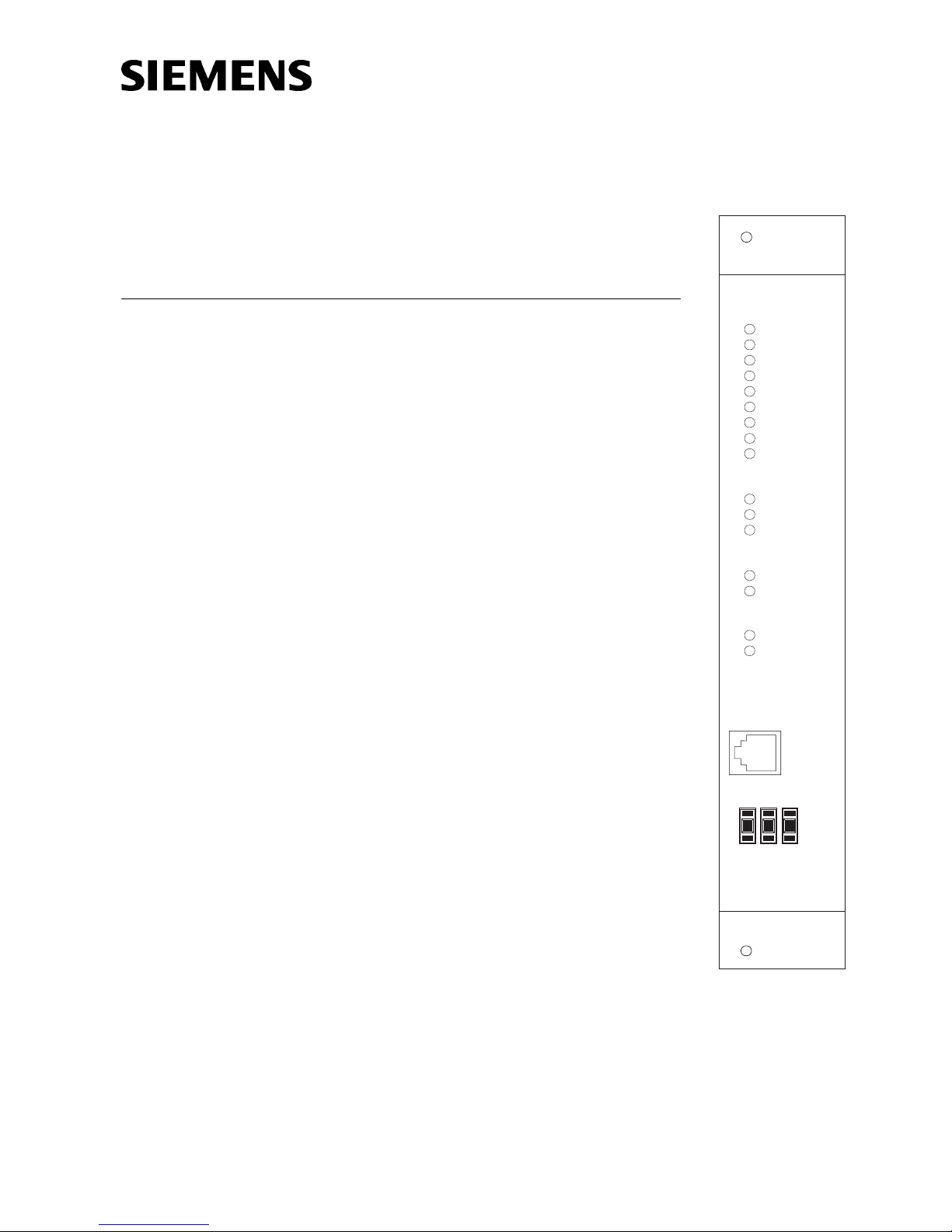
NIC-C
RESET
POWER
CARD FAIL
CAN FAIL
HNET FAIL
XNET FAIL
GND FAULT
LOOP A FAIL
LOOP B FAIL
ACTIVE NETWORKS
CAN
HNET
XNET
HNET/XNET STYLE
STYLE 7
STYLE 4
GROUND FAULT
ENABLED
DISABLED
NETWORK
PORT
+
+
+
3
1
2
-
-
-
HNET
A single NIC-C provides either HNET or XNET. The
CAN interface is available regardless of the HNET/
XNET selection.
The NIC-C supervises each network to insure proper
operation. Any faults that are detected by the NIC-C
are reported to the PMI for annunciation. In addition,
the NIC-C has diagnostic LEDs that indicate which
faults have been found. Individual LEDs are included
for HNET/XNET Loop A and Loop B faults, as well as
P/N 315-033240-4
Figure 1
NIC-C Network Interface Card
Siemens Building Technologies
Fire Safety

an LED for complete failure of the HNET or XNET network or the CAN network. The
NIC-C can also be configured to perform ground fault detection on both networks.
Features The NIC-C isolates short circuit faults to each individual segment of the HNET/XNET
network. If a short occurs, only the segment of wire between the two NIC-Cs is
affected. In a Style 4 system the network will be divided into two sections. Communication in each of the sections will continue. For a Style 7 network, the fault will
be detected and the network will continue to operate as a single network.
An HNET/XNET network monitoring jack is included for connection of diagnostic
tools. This jack is located on the front bezel.
The NIC-C supports the LCM-8/SCM-8/FCM-6/OCM-16/SIM-16 CAN modules.
LEDs are visible through the front bezel to indicate the NIC-C configuration. All
switch selectable options are displayed here. This allows for easy confirmation of
the NIC-C configuration settings without removing the card from the CC-5.
The NIC-C is compatible with the XNET Bridge.
OPERATION Network supervision is accomplished through passive monitoring of the network
signals. No additional bandwidth is required. Each NIC-C continuously monitors all
networks for activity and reports any problems to the PMI. Restoration of faults is
dynamic and does not require a system reset.
Controls and Indicators The front panel of the NIC-C contains one reset switch, fifteen LEDs, one network
port and one HNET address switch as shown in Figure 1
A reset switch is located on the top of the front panel. Pushing the reset switch reinitializes the NIC-C operation.
The LEDs follow the reset switch and their functions are defined as follows:
POWER (Green) Normally ON. When illuminated, indi-
cates that power for the NIC-C is applied
to the card.
CARD FAIL (Yellow) Normally OFF. When illuminated, indicates
that the card microprocessor has failed.
CAN FAIL (Yellow) Normally OFF. When illuminated, indi-
cates that all CAN modules connected to
the NIC-C are not communicating.
HNET FAIL (Yellow) Normally OFF. When illuminated, indi-
cates that the HNET communication with
the NIC-C has terminated and the card
goes into degrade mode.
XNET FAIL (Yellow) Normally OFF. When illuminated,
indicates that the XNET communication
with the NIC-C has terminated.
GND FAULT (Yellow) Normally OFF. When illuminated, indi-
Siemens Building Technologies
Fire Safety
cates that the NIC-C has detected either
a negative or positive ground fault on its
network.
P/N 315-033240-42

LOOP A FAIL (Yellow) Normally OFF. When illuminated,
indicates that the NIC-C has detected a
trouble on Loop A (open circuit or short
circuit).
LOOP B FAIL (Yellow) Normally OFF. When illuminated, indi-
cates that the NIC-C has detected a
trouble on Loop B (open circuit or short
circuit).
ACTIVE NETWORKS: CAN (Green) Normally OFF. When illuminated, indi-
cates that the CAN network is enabled.
ACTIVE NETWORKS: HNET (Green) When illuminated, indicates that the
HNET network is enabled.
ACTIVE NETWORKS: XNET (Green) When illuminated, indicates that the
XNET network is enabled.
STYLE 7 (Green) When illuminated, indicates that the
HNET/XNET is configured as Style 7(see
Pre-Installation - S3 on page 4).
STYLE 4 (Green) When illuminated, indicates that the
HNET/XNET is configured as Style 4
(see Pre-Installation - S3 on page 4).
ENABLED (Green) When illuminated, indicates that ground
fault detection is enabled (see PreInstallation - S1 below).
DISABLED (Green) When illuminated, indicates that ground
fault detection is disabled (see PreInstallation - S1 below.
A three-position switch at the bottom of the front panel is used to set the HNET
network address of the NIC-C.
PRE-INSTALLATION The following components must be set prior to inserting the card into the CC-5
(refer to Figure 2):
S1, Ground Fault Detection Control: Press the lever down to enable ground
fault detection. Move the lever to the up position to disable ground fault detection.
(Refer to Figure 2.)
It is recommended to enable ground fault detection on ONLY one NIC-C in the system.
(One for HNET and if used, one for XNET.) If multiple NIC-Cs have ground fault detection
enabled, multiple troubles will be reported to the PMI when a ground fault is present.
S2 Network Address Switch: Set the three-digit HNET network address for the
NIC-C using the three-position switch located near the bottom of the front panel.
(Refer to Figure 1 for the location of the switch.) The address for the NIC-C must be
the same as the address selected for it in the Zeus Programming Tool. To increment
each digit of the address, press the + button above the desired digit; to decrement each digit, press the - button below the desired digit. The range of allowable
addresses is from 001 to 251 (leading zeros must be used).
Siemens Building Technologies
Fire Safety
P/N 315-033240-43
 Loading...