

Page 1

Network ID Camera
Installation and Startup
SP
NIC2-2 (with DICOM)
© Siemens AG 2005
The reproduction, transmission or
use of this document or its contents
is not permitted without express
written authority. Offenders will be
liable for damages. All rights,
including rights created by patent
grant or registration of a utility
model _or_ design,_are_ reserved.
English
Print No.: SP00-000.814.05.01.02 Doc. Gen. Date: 10.05
Replaces: n.a.
Page 2

Installation and Setup Manual
Publication No. 201101
October 2005
NIC2-2
Network ID Camera
Page 3

Page 4

PLEASE NOTE
The information contained herein is based on the experience and knowledge rela-
ting to the subject matter gained by Triacon prior to publication.
No patent license is granted by this information.
Triacon reserves the right to change this information without notice, and makes no
warranty, expressed or implied, with respect to this information. Triacon shall not be
liable for any loss or damage, including consequential or special damages, resulting
from the use of this information, even if loss or damage is caused by Triacon's neg-
ligence or other fault.
© Triacon AB, Swed en 2005
Page 5

Page 6

NIC2-2 · Installation and Set-up Manual Publication no. 201101
Contents
1 General 1
2 Installation 1
2.1 Unpacking............................................. ...........................................1
2.2 Installation Details...........................................................................1
3Setup 3
3.1 Getting int o setu p mode............................ ............................... ......3
3.1.1 Resetting to customer default ........................................................ .... .. ...3
3.1.2 Main conf iguration window..................... ................. ......................... .......3
3.2 Picture settings ...............................................................................4
3.2.1 Some frequently used words ...................................................................5
3.2.2 Picture , Win1/Win2....................................... ................. ......................... ...5
3.2.2.1 Editing a field.....................................................................................................6
3.2.3 Settings Win1/Win2...................................................................................8
3.2.4 Menus.........................................................................................................9
3.2.5 Auto seque nc e.................................................. ................ ........................9
3.3 Bookinglist configuration.............................................................11
3.3.1 Settings ....................................................................................................11
3.3.2 Define input fields............................ ................. ......................... .............12
3.3.3 Link field to patient window...................................................................12
Triacon AB Sweden i October 2005
Page 7

Publication no. 201101 NIC2-2 · Installation and Set-up Manual
Contents
3.4 Communication param.................................................................12
3.4.1 Communication parameters Channel: HOST .......................................13
3.4.1.1 Protocol set-up................................................................................................14
3.4.2 Communication parameters Channel: AUX1.................. ......................14
3.4.2.1 Protocol set-up SIEMENS Mammomat® 3000...............................................15
3.4.2.2 Protocol set-up SIEMENS Mammomat® 300.................................................16
3.4.2.3 Protocol set-up SIEMENS Balance.................................................................17
3.4.2.4 Protocol set-up PLANMED..............................................................................17
3.4.2.5 Protocol set-up I-IMAGING.............................................................................18
3.4.2.6 Protocol set-up LORAD...................................................................................19
3.4.2.7 Protocol set-up GE Medical System Senographe...........................................20
3.4.2.8 Protocol set-up GXDP.....................................................................................21
3.4.3 Communication parameters Channel: AUX2.................. ......................22
3.5 NICLan configuration ...................................................................23
3.5.1 NICLan Mode.................................................... .......................... .............24
3.5.2 TCP/IP.......................................................................................................25
3.5.3 FTP ...........................................................................................................25
3.5.4 DICOM......................................................................................................26
3.5.4.1 DICOM Tags...................................................................................................27
3.5.4.2 Edit a Tag........................................................................................................28
3.5.5 CF Files....................................................................................................28
3.6 Settings..........................................................................................29
3.7 Remote control.............................................................................. 30
3.7.1 Save and Load a Set-up.......................................................................... 30
4 Upgrading the firmware 31
4.1 Download the firmware ................................................................31
October 2005 ii Triacon AB Sweden
Page 8

NIC2-2 · Installation and Set-up Manual Publication no. 201101
Contents
5 Error Messages 33
5.1 Illegal value....................................................................................33
5.2 The adjustment may be max 32...................................................33
5.3 Out of storage for FTEXT........................ ..................... .................33
5.4 Length must be between 1 and 8 .................................................33
5.5 Communication error ....................................................................33
5.6 Unknown programming err or....... ............................... .................33
5.7 Wrong Dicom Licence Code! .......................................................33
Triacon AB Sweden iii October 2005
Page 9

Publication no. 201101 NIC2-2 · Installation and Set-up Manual
Contents
Blank Page
October 2005 iv Triacon AB Sweden
Page 10
NIC2-2 · Installation and Set-up Manual Publication no. 201101
1. General
This manual describes how to install and setup the Network ID Camera herein
called NIC. This includes anything from installation to setting-up what the picture printed on the film should look like, which language for the display, to how
it should communicate with a booking system.
This manual is written for software version 3.32 and it is assumed that language is set to English. Note that you may select language to English which
causes all texts to be displayed in English, but still select country to the country
you are in to get country-dependent information, like date format and PID number, correct.
2. Installation
2.1 Unpacking
Check that the cardboard box is undamaged and has no holes or deep scratches. Any damage must be reported to the transport company or the supplier
whenever it can be suspected that the camera has been damaged during
transport.
The box contains the camera, an operator's manual in local language and the
power cord. The keyboard should be equipped with the country dependent
keycaps.
2.2 Installation Details
After unpacking the camera it should be placed on a steady table or shelf. If the
camera is operated in mobile units like mammography screening buses, or
where there is a risk of the camera falling down, it should be fastened to the
surface with two screws mounted from the inside of the camera through two
holes in the bottom plate with suitable screws.
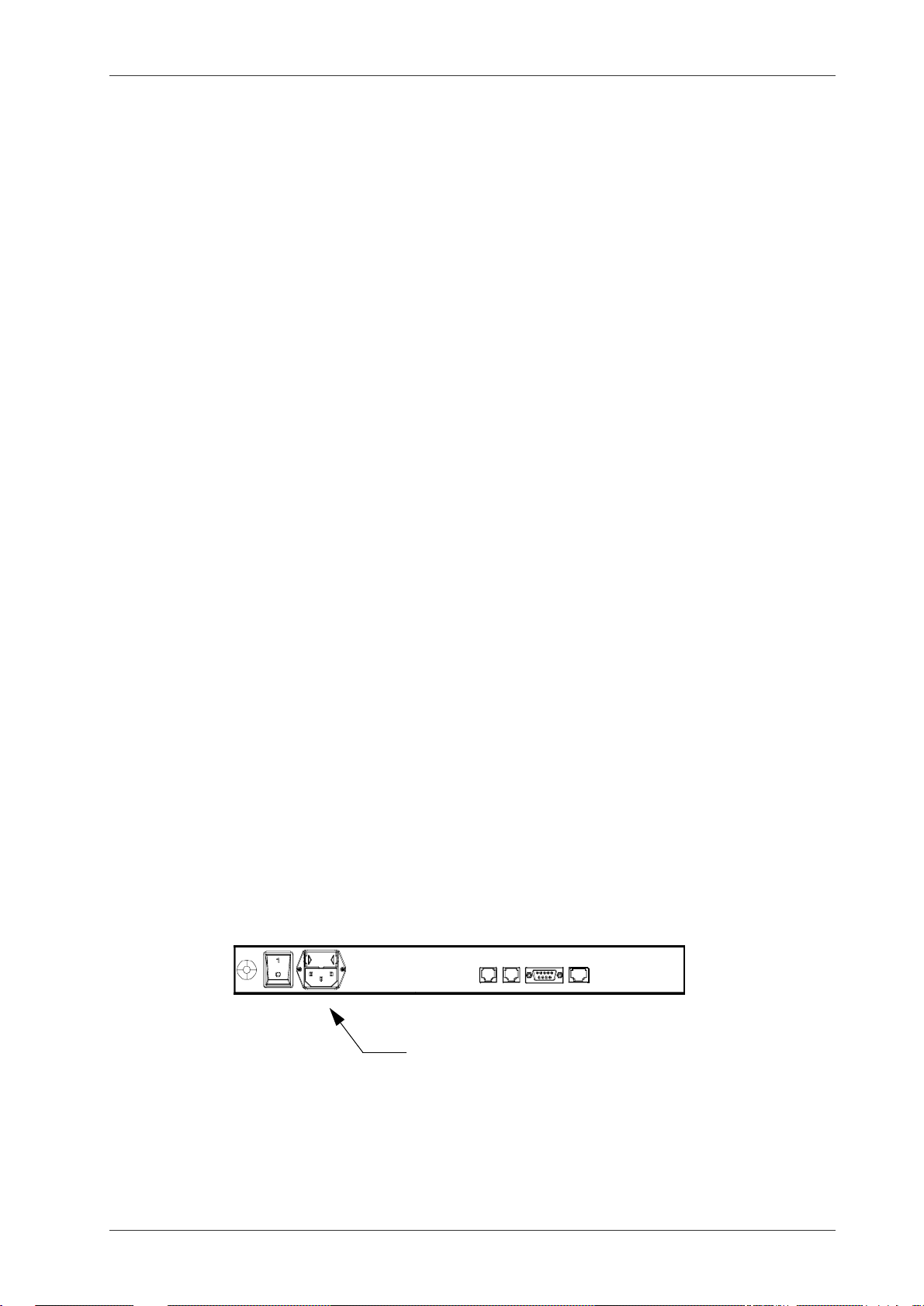
The power cord should be connected to the power receptacle on the backside
of the camera and to wall outlet.
No voltage selection is necessary, the camera can be operated at any
voltage from 100 to 250 VAC 50/60Hz.
Power receptacle
Triacon AB Sweden 1 October 2005
Page 11
Publication no. 201101 NIC2-2 · Installation and Set-up Manual
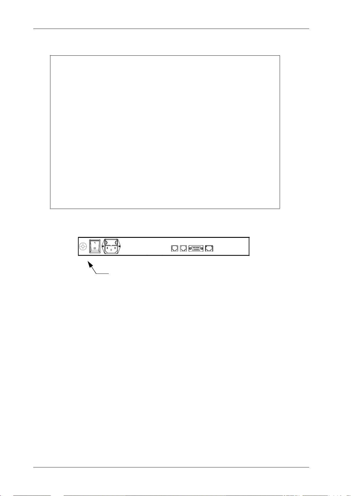
Warning
The Network ID Camera is classified as a Medical Device and
fulfils EN 60950.
According to European Safety Regulations for Medical Equipments, the following conditions must be fulfiled:
- if the camera is operated within a distance of 1.5 m from
the patient, it must be connected to the equipotential
2
equalization device (E
2
E
D with cable must be provided by the customer.
The purpose of the E
D).
2
D is to ensure that all medical and
other equipments are connected to the same ground potential.
- if the camera is connected to a Medical Equipment according to EN 60601-1 ( e.g. safety ground or data connections) the safety standard EN 60601-1-1 has to be
met and documented.
E2D plug - Connector for the cable coming
from the equipotential bushbar.
October 2005 2 Triacon AB Sweden
Page 12
NIC2-2 · Installation and Set-up Manual Publication no. 201101
3Setup
This section describes how the set-up of the camera is done. It assumes that the operator
is familiar with the camera.
3.1 Getting into setup mode
Make sure the camera displays the main window which is the window that comes up after
the initial screen with the Triacon logo. The window shows:
Date:26.10.2005 Time:11:31:34
Selected picture : Win1
Manual Booking Memory Picture
To get into setup mode, press Shift F4 (the right soft-key while holding any of the two shift
keys down). A new window will appear asking for a password.
The Network ID Camera will remember the password for about 15 mi nutes and wil l not ask
you for the password again, if you exit and the n enter set-up mode again within 15 minutes .
This is to eliminate the need to re-type the password every time you leave setup mode to
test a configuration.
3.1.1 Resetting to customer default
Get into setup mode as described in chapter 3.1. Then press Ctrl-E. This will reload the standard setup and restart the camera.
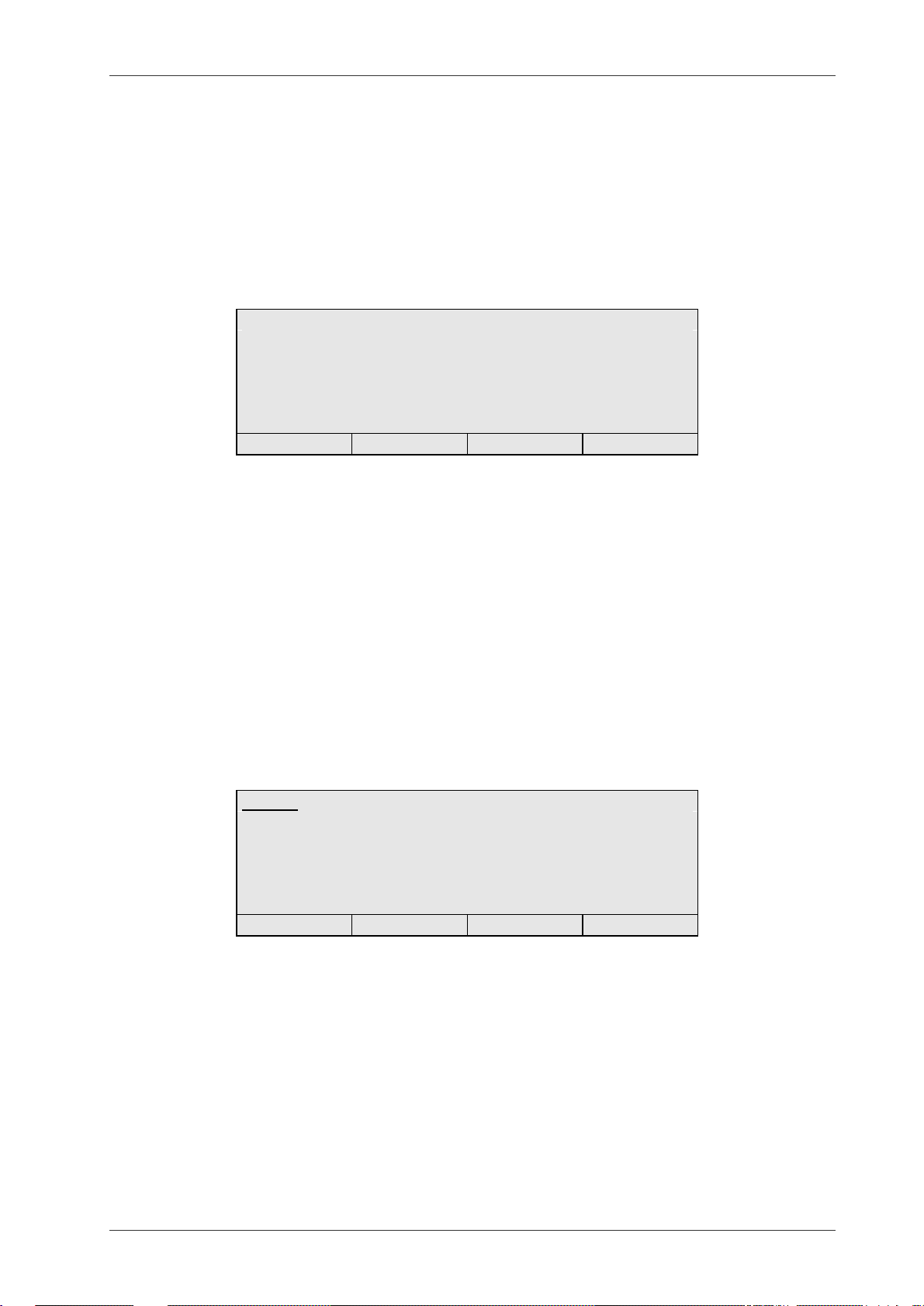
3.1.2 Main configuration window
Get into configuration mode as described in chapter 3.1.
Setup Ver 3.32
Picture settings
Bookinglist configuration
Communication param
NICLan configuration
Settings
Lock Exit
Use the up- and down arrow keys to move the highlight bar up and down. Select item by
pressing ENTER.
The soft-keys are used as follows:
Lock Lock the set-up with a password. Will make the Network ID Camera ask for
password the next time set-up is entered. An alternative to LOCK is to wait
for the password time-out.
Exit Exit set-up mode.
Picture settings
Here you can set details of how and what will be printed on the film.
Triacon AB Sweden 3 October 2005
Page 13

Publication no. 201101 NIC2-2 · Installation and Set-up Manual
Bookinglist configuration
Here all settings for manual entry of data to bookinglist is configured.
Communication param
Here all settings regarding the communication between the Network ID Camera and the equipment connected to any of the four communication ports can
be changed.
NICLan configuration
Here all settings related to a TCP/IP communication is defined.
Settings Here all settings of a more general nature can be changed, e.g. which lan-
guage the Network ID Camera speaks.
Sensor adjustment
This selection will show a picture showing the status of the three cassette
sensors. For detailed information, please refer to the Service manual.
Test functions
Here parameters regarding the opening of the cassette window can be set.
For detailed information, please refer to the Service Manual.
NOTE: This should only be done by trained servic e personnel.
Serial analyzer
Here all data, received on HOST or NE T serial communication port , is listed.
For detailed information, please refer to the Network Installation Manual.
Remote control
Here the down-/up- load of a set-up is performed.
System logger
Here are listed errors and abnormal situations. For detailed information,
please refer to the Service Manual.
Setup Manager
This entry is only used by the production personal.
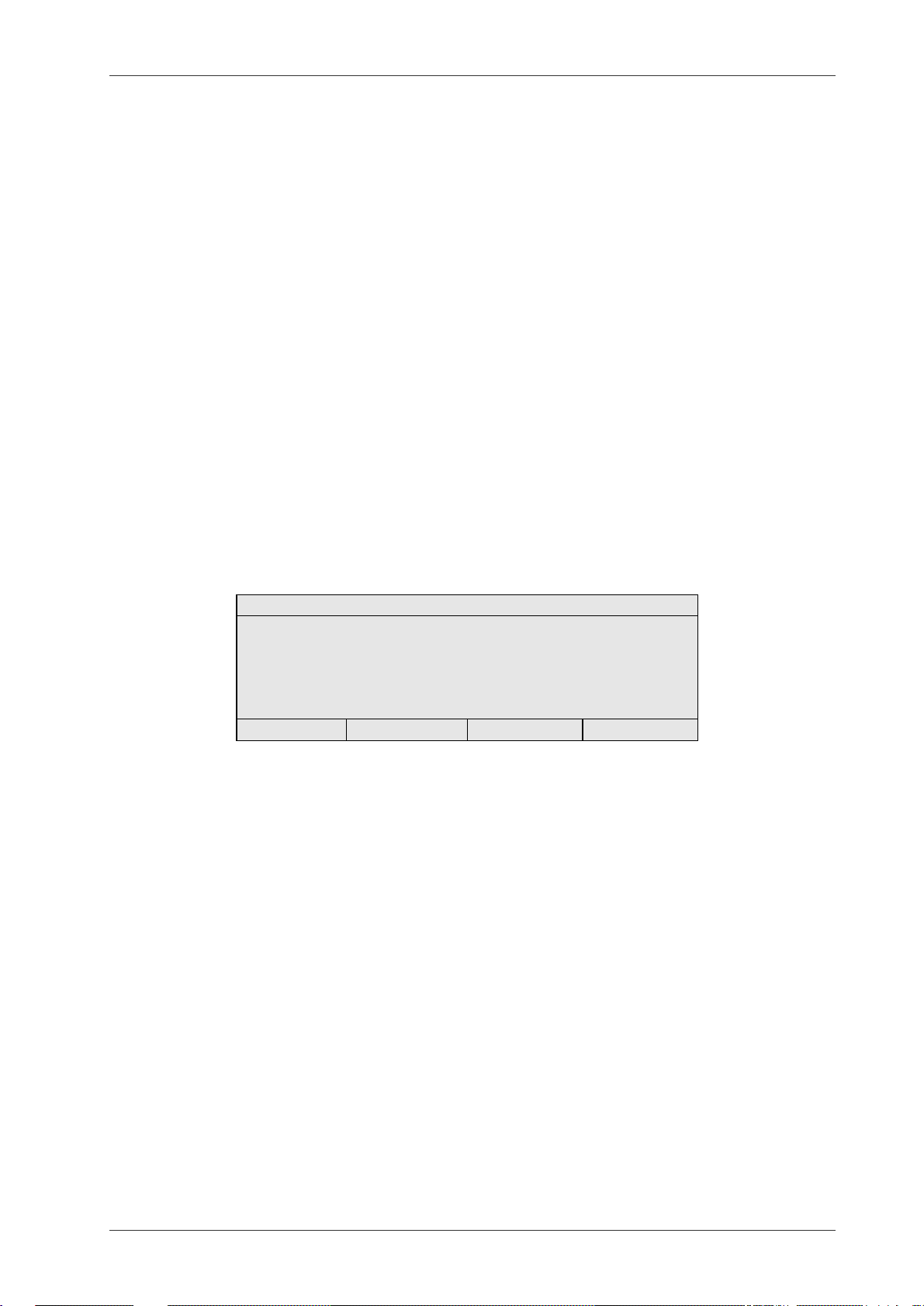
3.2 Picture settings
Choosing this selection will present five new alternatives
Picture settings
Picture Win1:
Settings Win1:
Picture Win2:
Settings Win2:
Menues
Previous Next Exit
Here the layout of the picture printed on the film is defined. Two different pictures can be
defined, "Win1" and "’Win2". This means that it is possible to have two different configurations, one under Picture Win1 and another under Picture Win2. The picture names
are editable to any name corresponding to their use.
October 2005 4 Triacon AB Sweden
Page 14
NIC2-2 · Installation and Set-up Manual Publication no. 201101
3.2.1 Some frequently used words
Field This is what a unit of information is called when it is displayed on the picture.
A field contains, for example, the name of a patient or the current date or current time. A picture is made of a number of fields, and each field can be
placed anywhere within the picture. A field also contains information about
how the information should appear on the picture, for example the s ize of the
text.
Pixel A pixel is a small dot of which all characters are built on the display. Position
on the display is given in pixels. To be able to calculate how much information
will fit into the window, you must know the following.
The C1 window is 64 pixels high and 240 pixels wide.
The C1N window is 48 pixels high and 240 pixels wide.
A character is 16 pixels high and 12 pixels wide, if the large font is use.
A character is 12 pixels high and 9 pixels wide, if the medium font is use.
A character is 8 pixels high and 6 pixels wide, if the small font is used.
Font The appearance of the text on the film/display is determined by the font se-
lected. Currently three fonts are available, LARGE, MEDIUM and SMALL.
3.2.2 Picture, Win1/Win2
If Picture Win1 or Win2 is selected, a fieldlist will appear.
No Field Length Row,Col
01: B-date 10 0, 0
02: Name 20 12, 0
03: PID 11 15,174
04: Date 10 0,160
05: Time 5 0,104
Place New Remove Exit
This fieldlist shows all fields that are defined for selected picture. The up and down keys can
be used to step through all fields. The window will automatically scroll to display more items.
To add a new item, place the cursor on the position where you like to add a field and pres s
the NEW soft-key. This will make the Network ID Camera duplicate the field at the cursor
and you can then edit one of the copies as you wish. The maximum numbers of fields are
50 for each window.
To remove an item, place the cursor on the field you want to delete, and press the REMOVE
soft-key. This will immediately remove the selected item.
To move a field (i.e. give it another position on the picture printed on the film) press the
PLACE soft-key. This will bring up another window where the sele cted field is di splayed as
a white box representing the size of the field, and all other fields are displayed as other
strings of characters selected to represent the type of the field (D for date field N for name
field). The current field can now be moved by the four arrow keys. If shift+arrow key is
pressed the field will step 6 pixels left/right and 8 pixels up/down. When a good position is
found just press the enter key to leave the window. Ex perience has shown that this is a good
method of finding out where to place the field. It is, however, difficult to find the exact position, as the fields are often placed one or two pixels off. Therefore, the optimal procedure is
to place all fields using this method, and then to check all positions manually and correct
them by entering their positions by numbers as described below under "Editing a field".
Triacon AB Sweden 5 October 2005
Page 15

Publication no. 201101 NIC2-2 · Installation and Set-up Manual
3.2.2.1 Editing a field
To change a parameter of a fi eld, place the cursor on the field and press the enter key. This
will open a new window:
Field definition Field:02
Type: Name Leghth: 20
Row: 12 Column: 0
Font: Medium
Previous Next Save
Type tells what kind of information is displayed in this field. The following types ar e
available.
Name - The name of the patient. The user may enter any information. This
field must not be empty.
PID - The PID number of the patient. When entering the PID number, only
the format that is used in the country for which the camera is configured is
allowed. If a check-digit exist it is also checked, and the user is forced to either correct the PID number or explicitly tell that the number is not valid by
pressing the Shift-F1 key.
Number - An integer. Allows only numeric characters to entered.
Text - Any text in any format can be entered.
AP/PA - Anterior or Posterior. This tells, whether the X-ray picture is taken
with the X-ray tube in front or behind the patient. Apart from displaying it in
the film, the information is used by the Network ID Camera to mirror the picture when the picture is taken PA.
Menu - A menu allows the user a selection from a number of predefi ned text
strings. Five different menus can be defined, and each of them can have 16
alternatives. In this window you only have to chose which of the five menus
you will use. When you leave the type field (press enter) a new field will appear in the window, called m enu. Here the number of the menu to use can be
entered.
F-Text - Fixed text. This is used to enter text that will always be displayed
like the name of the hospital. When you leave the type field (press enter) a
new field called "Fixed text" will appear at the bottom of the window, allowing
you to enter the text to display.
H-line - Horizontal line. Will display a horizontal line on the picture. Take
care not to put the line b ehind any other field because thes e other fields may
overwrite the line. When you leave the type field (press enter) a new field
called "Width" will appear at the bottom of the window, allowing you to enter
the width of the line.
V-line - Vertical line. Details see H-line.
Date - Print current date. When the type field is left a new entry will appear
called format. Here the date format can be selected. If the format you want is
not available it can still be created by using three different date fields, one
each for year, month, and day with separating characters inserted as F-text
fields. Note that months can be displayed ei ther as a two-digit number (MM)
or three-letter text (MMM).
October 2005 6 Triacon AB Sweden
Page 16

NIC2-2 · Installation and Set-up Manual Publication no. 201101
Time - Prints current time. Functions the same way as the DATE field.
COMM - Communication. This field is used if the Network ID Camera is con-
nected to other equipment that sends data to the Network ID Camera, for example an X-ray unit that can send information about kV and mAs. When the
type field is left a new entry will appear called Comm. Thi s item wi ll present a
list of the type of information available. The type of information highly depends on the kind of equipment connected. Please refer to chapter ”3.4.2
Communication parameters Channel: AUX1” on page 14 and the Network Installation Manual for more information.
P-text - Persistent text. Works as a text field but with th e difference that the
text inserted here will remain unchanged until it is edited even if the patient
data window is closed and then opened again.
B-date - The patient data of birth. On ly digits are allowed to b e entered. The
date format depends on the country setting.
Special - This field consist of some special function like calculation of the
patient age and to generate special characters. If the AGE function is to be
used a B-date field must also be defined. T his because the age is cal culated
from the B-date field and the built-in real time clock.
Technol - Technologist i nitial. Works as a P-text field but with the difference
that this field is linked to menu no.1. If menu no.1 and a technologist initial
are defined, an ’Auto sequence’ can be used.
H-text - Text field dedicated for the hospital name. Works as a F-text field
but is detected by, and editable from, the NIC Manager program.
Length The length of the field.
Row The pixel row where the upper edge of the characters of the field should be
displayed.
Column The pixel column where the left side of the character should be placed.
Font The size of the character. Select between large (h=16, w=12), medium
(h=12, w=9) or small (h=8, w=6).
Menu This field only appears when the field type is Menu. Enter the number of the
menu to be used. Please refer to ”3.2.4 Menus” on page 9 for details.
F-text Fixed text. This field only appears when the field type is F-text. Enter the text
to be displayed. The maximum numbers of F-texts are 30 divided among the
two windows.
Format This field only appears when the field type is date or time. See Date above
for more information.
Comm Communication item. This field presents a list with the information that is sent
from equipment connected to the Network ID Camera. The kind of information highly depends on the kind of equipment connected. Please refer to
”3.4.2 Communication parameters Channel: AUX1” on page 14 and Network
Installation Manual.
Width This field only appears when the field type is V-line or H-line. See H-line
above for more information
Type This field only appears when the field type is special. See special above for
more information
Triacon AB Sweden 7 October 2005
Page 17

Publication no. 201101 NIC2-2 · Installation and Set-up Manual
3.2.3 Settings Win1/Win2
If this entry is selected, the following will be displayed
Settings
Status : Used Text : Normal
Exposure: 100ms Location: Bottom
Vert adj: 0
Name: Def proj: AP
Previous Next Save
The cursor is located at "Status" and can be moved between the different settings by pres sing up- and down-arrow keys. If the softkeys Previous and Nex t are visible i t is two or m ore
predefined values that can be selected by pressing the corresponding function keys F2 and
F3.
The following settings can be performed:
Status Toggle between Used/Not used (i.e. enable/disable the picture). If one pic-
ture is switched to "Not used" the other one will automatical ly be switched to
"Used". A "Not used" picture can not be accessed by the operator. Factory
default is Used.
Exposure Basic exposure time in milliseconds. A value between 10 and 65535 can be
set. Factory default is 100ms.
The actual exposure time is the basic exposure time set in this window mul-
tiplied by a factor determined by the exposure correction set in the exposure
window that is opened from the patient data window. The c orrection factor is:
123 456789
0.5 0.6 0.71 0.84 1 1.19 1.44 1.68 2
Name The name of this picture. Can be edited to any name wi th a maximum lengt h
of 15 characters. Factory default is "Win1" and "Win2".
Text Toggle between Normal/Inverted. Determine whether the picture should
show white text on black background or black text on white background. Factory default is Normal.
Location Toggle between Bottom/Top. Determine whether the picture should be pr int-
ed on bottom or top of the film. Factory default is Bottom.
NOTE! If a window is set-up for a MIN-R2 cassette bottom m arking and then
is changed to top marking the lower 16 pixel-lines of the image will be placed
outside the cassette window. This means that the whole image must be
moved 16 pixel-lines up, field by field, to fit the MIN-R2 cassette window. If a
Standard C1 cassette is used, no adjustments is needed when swapping
from bottom to top marking.
Vert adj Offset between operator- and exposure display. The picture which will be
printed on the film can be adjusted down. Maximum adjustment is 32 pixellines. Factory default is 0.
Def proj Setting if AP or PA projection should be default. Even if there is no AP/PA
field defined, the picture will be mirrored according to this setting.
October 2005 8 Triacon AB Sweden
Page 18

NIC2-2 · Installation and Set-up Manual Publication no. 201101
3.2.4 Menus
Menus can be defined here. A menu is a type of field where the user can select from a set
of predefined texts. Five different menus can be defined. Each of them c an have 16 different
selections. Any menu can be used any number of times by either Win1 or Win2 picture, or
both.
When "Menus" is selected from the window described in chapter 3.2 the following window
is displayed
No Len Alternative
1: 4 SIN,DX,MIKT
2:
3:
4:
5:
New len Exit
Here menu 1 is defined. It has a length of 4 and contains the alternatives SIN, DX and MIKT.
To create a new menu, move the cursor to line, for example No. 2, and press the F2-key. A
new window will appear asking you for the number of characters of the longest alternative
in the list. This may be a number between 1 and 8. After enter ing an appropri ate value the
following window appears
No Proj Alternative
01: “ “
02: “ “
03: “ “
04: “ “
05: “ “
AP/PA Previous Next Save
Now you can enter the text for the alternatives. Keep in mind that the last alternative entered
must not be a blank, because the program cannot see the difference between a blank alternative and no alternative at all. Instead it is better to put the blank alternative at the first
place, because the first alternative is selected by default. If an alternative is longer than allowed by the length set, it will simply be cut to the proper length when the save key is
pressed.
A projection can be set for each alternative. It will change the AP/PA setting to the AP/PA
setting set for the menu item. The Proj can be toggled Off/AP/PA by pressing the F1 softkey.
3.2.5 Auto sequence
If a connected mammography X-ray stand does not support the view value, the so-called
”Auto Sequence” can be used. This means that the technologist does not need to enter the
view for each film marking manually.
Three things have to be defined to get this working, the view items, the ”Technol” field and
finally the auto sequence for each technologist which is done in normal operational mode.
The view items is defined in ”Menu 1”. Goto ”Menues” as described in ”3.2.4 Menus” and fill
in wanted view parameters. Maximum 16 items can be entered. Ex.
RCC, LCC, RMLO, LMLO, RML, LML, RLM, LLM, RXCCL, LXCCL, RAT, ID, CV and TAN.
Triacon AB Sweden 9 October 2005
Page 19

Publication no. 201101 NIC2-2 · Installation and Set-up Manual
Note that first item is ”Blank”, this because first item is default.
No Proj Alternative
01: “ “
02: “RCC “
03: “LCC “
04: “RMLO “
05: “LMLO “
AP/PA Previous Next Save
Next step is to define the ”Technol” field as described in ”3.2.2 Picture, Win1/Wi n2” on page
5.
To define an auto sequence the NIC must be set in normal operation mode. From the main
window, press SHIFT+F3 to enter the ”Technologist setup”.
Technologist set-up
00: “LEK “ RCC LCC LMLO RMLO
02: “ “ ----- ----- ----- ----03 “ “ ----- ----- ----- ----04: “ “ ----- ----- ----- ----05: “ “ ----- ----- ----- ---- Previous Next Exit
Here is a technologist initial ”LEK” wi th the autosequence ”RCC, LCC, LMLO and RMLO defined. Use the up- /down arrow keys to select a new row and enter a initial. Press ENTER
to move the cursor to the first item in the sequence, use the F2- and F3 key to select a view.
Press ENTER again will move the cursor the the next item. Maximum 20 initials/auto sequences can be defined.
To test an auto sequence. Enter the patient data window, fill in patient data and enter a defined technologist initial in the ’Technol’ field, e.g. ’LEK’. This will bring up the first item defined for the initial LEK. Insert a cassette into the NIC slot and mak e an exp osure, i.e. flas h
a film, will change the view to next defined value, from RCC to LCC, a new exposure from
LCC to LMLO and so on.
Beatle, Judy
14:32
09.11.2005
01585112 23.06.1955
LEK RCC
Exit
Technol field Menu field
October 2005 10 Triacon AB Sweden
Page 20

NIC2-2 · Installation and Set-up Manual Publication no. 201101
3.3 Bookinglist confi gu ration
Here the configuration of the internal bookinglist is made. Choosing this selection will
present three new alternatives.
Bookinglist configuration
Settings
Define input field
Link field to patient window
Previous Next Exit
If a booking- or RIS-system is to be used to download patient data to the booking list it is
only one thing to be set here. Under settings "kind of input" must be defined. All other settings regarding the communication protocol and patient data settings are made under section "Communication parameters", please refer to ”3.4 Communication param” on page 12.
3.3.1 Settings
Settings
Kind of input HOST
Default sortorder NAME
Erase list at power interrupt YES
Previous Next Save
The cursor is located at "Kind of i nput" and can be mov ed b etween the diffe rent settings by
pressing up- and down-arrow keys. With the s oftkeys Previous and Next the values can be
selected by pressing the corresponding function keys F2 and F3.
The following settings can be performed:
Kind of input
Toggle between HOST/MANUAL. Determine whether the data is downloaded from a host system or if it shall be manually inserted. Default setting is
HOST.
Default sortorder
Toggle between NAME/PID. Determine whether the booking list shall be sorted by name or the personal identity number. Default setting is NAME.
Erase list at power interrupt
Toggle between Yes/No. If set to Yes the booking list will be erased every
time the Network ID Camera is powered down. If set to No the booking list
will remain unchanged after a power interrupt. Default setting is Yes.
Triacon AB Sweden 11 October 2005
Page 21

Publication no. 201101 NIC2-2 · Installation and Set-up Manual
3.3.2 Define input fields
No Field Len Label
01:PID 11 “PID ”
02:NAME 20 “Name ”
03:B-DATE 10 “Birth ”
04:UNUSED 10 “ ”
05:UNUSED 10 “
Previous Next Save
Maximum five entries can be defined. Field types available are; PID, NAME, B-DATE and
TEXT. The maximum number of characters to enter in each field must be set, this is done
in the "Len"-column. A label for each field can be defined, here can any name be entered
with maximum eight characters.
Ex. The definitions above will look like this for the operator while in "Manual data entry to
booking list".
Bookinglist 250 free 261005
PID:_
Name:
Birth:
Exit Save
3.3.3 Link field to patient window
This window is used to set-up a translation table between a TEXT-field defined under 'Defi ne
input fields' and the field number in the Win1 and Win2 window of the Network ID Camera.
Scr Win1 Win2
00: 0 0
01: 3 0
02: 0 0
03: 0 0
04: 0 0
Win1 Win2 Save
Use F2 and F3 keys to change between Win1 and Win2 columns.
Ex. The B-date field defined in c hapter 3.3. 2 'Defi ne i nput fields' shall be linked to field no.
3 in chapter 3.2.2 'Picture Win1/Win2'. We need to enter the number three in column
Win1, row no. 02, see picture above.
3.4 Communication param
Selecting this item will pr esent a window where the c ommunication channels of the Network
ID Camera can be configured. This window works slightly different from the previous windows: instead of presenting a sub-menu where the item to configure is selected, function
keys are used to change what has to be configured. This scheme seemed better suited in
this situation where the user often quickly wants to switch between channels. Apart from
that, there is a protocol-dependent configuration window for each channel, which is opened
October 2005 12 Triacon AB Sweden
Page 22

NIC2-2 · Installation and Set-up Manual Publication no. 201101
from each channel configuration window by a function key. When the Communication parameters window is open the channel selected is displayed in the upper right corner of the
window. To select another channel, press the Channel (F1) soft-key. To configure a parameter of the selected protocol pres s the Shift Protocol (Shift-F1) s oft-key. Note that not all protocols have a protocol set-up associated.
This chapter does not cover all details of the Networ k ID Camera communication. For more
information please refer to the Network Installation Manual.
3.4.1 Communication parameters Channel: HOST
In this window the communication channel used to download patient data from a host computer is configured.
NOTE! If the text "Manual bookinglis t is enabled" is v isible the data input is expec ted to be
manually. To change this setting please refer to chapter ”3.3.1 Settings” on page
11.
Communication parameters Channel:HOST
Speed 9600
Parity NONE Groupname
Databits 8 bits Protocol DIRECT
Connection RS-232
Channel Previous Next Save
Move between the different settings by pressing up- and down arrow keys. Use the Previous
(F2) and Next (F3) keys to toggle between the alternatives.
Speed Set the speed of the channel, 300, 600, 1200, 2400, 4800, 9600, 19200,
38400 or 57600. Factory default is 9600.
Parity Set the parity used by the channel, NONE, EVEN or ODD. Factory default is
NONE.
Databits Set the number of bits used by the channel, 7 or 8 bits. Factory default is 8
bits.
Connection Selects where the host computer is connected.
RS-232 means that the host computer is connected to the 9pin DB connector
labelled HOST, used for serial poit-to-point communication.
RS-422 means that the host computer is connected to the RJ-45 connector
labelled NET, used for serial multi-drop communication.
Factory default is RS-232.
Groupname Sometimes several cameras are connected in parallel which means that all
cameras will receive patent data for all patients. Setting groupname will give
the camera a name, so that the camera will only received data addressed to
this name.
Protocol Here the protocol is selected. The following alternative are available:
2010B - Kodak 2010 compatible protocol with STX/ETX as if connec ted to
the 2010 communication box. B means connected to BOX.
2010D - Kodak 2010 compatible protocol without STX/ETX as if connect-
ed to a host computer instead of the 2010 network. D means Direct to host without box.
DIRECT - Network ID Camera direct protocol.
Triacon AB Sweden 13 October 2005
Page 23

Publication no. 201101 NIC2-2 · Installation and Set-up Manual
DOWNLOAD-Network ID Camera download protocol.
SLP100 - Protocol for printout to a label printer.
MAGNCARD -Protocol for magnetic card reader.
For more information, please read Network Installation Manual.
Char.tbl Only active for the Nordic countries.
Select which character table to use. A UNIX computer or a PC running MSDOS or Windows use different coding for national characters like the Swedish ÅÄÖ for example.
AUTO - Fortunately, there are mostl y no conflicts between the codes used in
the different character sets, which means that the Network ID Camera can apply the translation scheme for all character sets at the
same time without any conflicts. This is AUTO.
7bit - In some cases the characters []{}\| are used for national characters.
The 7bit setting will translate these characters. The translation depends on the country setting.
IBM - This is the PC/MS-DOS codepage 850 character set.
WIN - This is the MS-WINDOWS character set.
3.4.1.1 Protocol set-up
Select Protocol (Shift-F1) when DIRECT- or DOWNLOAD protocol is selected. This will
bring up the protocol set-up for the protocol.
This window is used to set-up a translation table between a field number used in the communication protocol and the field number in the Win1 and Win2 window of the Network ID
Camera. Use the up and down arrows to move to the field above and bel ow and use the F2
and F3 key to change between the Win1 and Win2 columns. Note that 15 fields are available. They appear by pressing the down arrow when you are at the bottom line. For more
detailed description please refer to the Network Installation Manual.
Scr Win1 Win2
00: 0 0
01: 0 0
02: 0 0
03: 0 0
04: 0 0
Win1 Win2 Save
3.4.2 Communication parameters Channel: AUX1
In this window the auxiliary communication channel no. 1 is configured. This channel is dedicated for communication with a X-ray stand.
Communication parameters Channel:AUX1
Speed 9600
Parity NONE
Databits 8 bits Protocol NONE
Channel Previous Next Save
October 2005 14 Triacon AB Sweden
Page 24

NIC2-2 · Installation and Set-up Manual Publication no. 201101
Move between the different settings by pressing up- and down arrow keys. Use the Previous
(F2) and Next (F3) keys to toggle between the alternatives.
Speed Set the speed of the channel, 300, 600, 1200, 2400, 4800, 9600, 19200,
38400 or 57600. Factory default is 9600.
Parity Set the parity used by the channel, NONE, EVEN or ODD. Factory default is
NONE.
Databits Set the number of bits used by the channel, 7 or 8 bits. Factory default is 8
bits.
Protocol Here the protocol is selected. Available alternatives are:
NONE - The channel is not used.
MMAT3000 - Used by Siemens Mammomat® 1000/3000.
MMAT300 - Used by Siemens Mammomat® 300.
BALANCE - Used by Siemens BALANCE.
PLANMED - Used by Planmed Models Classic, Sophie and Maxview.
SENOGRAPH - Used by Senographe Models DMR, DMRV2 and Senix.
SENO800T - Used by Senographe Model T800.
I-IMAGING - Used by Instrumentarium Mod els Alfa, Diamond and Performa
LORAD - Used by Lorad Model IV.
GXDP-P - Selects the General XRAY Data Protocol with poll function.
GXDP-NP - Selects the General XRAY Data Protocol without poll function.
For more information, please refer to the ’Network Installation Manual’.
3.4.2.1 Protocol set-up SIEMENS Mammomat® 3000
Pressing Shift Protocol ( Shift F1) when the MMA T3000 protocol is selected will bring u p the
protocol set-up for the SIEMENS Mammomat® 3000 protocol..
Define text for Mammomat 3000
Focus SF LF
Anode W Mo
Filter Rh Mo
Grid No grid Grid
0 Text 1 Text Save
This window is used to define a number of text strings. The Mammomat® 3000 sends a few
parameters as 0 and 1, whereas they should be presented as texts instead. This window is
used to define those texts. For more detailed information, please refer to the Mam momat®
3000 manual.
Each string may be up to 8 characters long. Use the up and down arrows to go to the row
below or above, and use "0 text"- and "1 Text" soft-keys to select column.
Creating the picture that will be printed on the film is done in the same way as usual selecting
the COMM field type.
NOTE! The communication protocol has to be set before setting up the picture, otherwise
the COMM field will display NONE.
Example
Triacon AB Sweden 15 October 2005
Page 25

Publication no. 201101 NIC2-2 · Installation and Set-up Manual
We want to create a COMM field that sha ll display the FOCUS. Create a new field and under
fielddefinition select Type COMM. The Mammomat® 3000 is sending ether 0 or 1 as the FOCUS parameter and the Network ID Camera is translating it to a text according to the protocol set-up above. In this case the texts are SF for 0 and LF for 1. With reference to this
settings, the length should be set to 2 and Comm to FOCUS. This means that we have to
define the length of this COMM field to two. Select Comm FOCUS will link the foc us data to
this field.
Fielddefinition Field:01
Type: Comm Length: 2
Row: 56 Column:108
Comm: Focus Font: Small
Previous Next Save
The field+ data do not include the unit (kV, mAs etc.). To add this, a F-text field with the appropriate text has to be inserted after or before the COMM field. Create a new field and under fielddefinition select Type F-text. E nter values for the row and c olumn to pl ace this field
at a position of your preference. Hint, use the Place function to position fields, see chapter
3.4.2 'Picture Win1/Win2'. Enter appropriate text under Fixed text.
Fielddefinition Field:02
Type: F-text
Row: 56 Column: 78
Fixed text: Font: Small
Focus
Save
These fielddefinitions will give us the text "F ocus" followed by the "FOCUS"-value at the c enter bottom of the patient data window.
3.4.2.2 Protocol set-up SIEMENS Mammomat® 300
Define text for Mammomat 300
Small focus: SF
Large focus: LF
Save
This window is used to define the focus text string. The Ma mmomat® 300 sends this parameter as 0 and 1, whereas it should be presented as text instead. This window is used to
define this text. For more detailed information, please refer to the Mammomat® 300 manual.
The string may be up to 8 characters long. Use the up and down arrows to go to the row
below or above and enter appropriate text.
Creating the picture that will be printed on the film is done in the same way as usual selecting
the COMM field type.
October 2005 16 Triacon AB Sweden
Page 26

NIC2-2 · Installation and Set-up Manual Publication no. 201101
NOTE! The communication protocol has to be set before setting up the picture, otherwise
the COMM field will display NONE.
Example
We want to create a COMM field that shall display the kV. Create a new field and under field-
definition select Type COMM. According to the Siemens Mammomat® 300 protocol the
length of the kV value is five. This means that we have to define the length of this COMM
field to five. Select Comm kV will link the kV data to this field.
NOTE! SIEMENS Mammomat® 300 is sending also the type together with the value, e.g.
’25 kV’..
Fielddefinition Field:01
Type: Comm Length: 5
Row: 56 Column:108
Comm: kV Font: Small
Previous Next Save
3.4.2.3 Protocol set-up SIEMENS Balance
No set-up is made for this protocol. The data input has the correct format which means that
no translations are needed.
Creating the picture that will be printed on the film is done in the same way as usual selecting
the COMM field type.
NOTE! The communication protocol has to be set before setting up the picture, otherwise
the COMM field will display NONE.
Example
We want to create a COMM field that shall display the kV. Create a new field and under field-
definition select Type COMM. According to the Si emens Balance protoc ol the length of the
kV value is six. This means that we have to define the length of this COMM field to six. Select
Comm kV will link the kV data to this field.
NOTE! SIEMENS Balance is sending also the type together with the value, e.g. ’12.3kV’..
Fielddefinition Field:01
Type: Comm Length: 6
Row: 56 Column:108
Comm: kV Font: Small
Previous Next Save
3.4.2.4 Protocol set-up PLANMED
No set-up is made for this protocol. The data input has the correct format which means that
no translations are needed.
Creating the picture that will be printed on the film is done in the same way as usual selecting
the COMM field type.
Triacon AB Sweden 17 October 2005
Page 27

Publication no. 201101 NIC2-2 · Installation and Set-up Manual
NOTE! The communication protocol has to be set before setting up the picture, otherwise
the COMM field will display NONE.
Example
We want to create a COMM field that shall display the kV. Create a new field and under field-
definition select Type COMM. According to the P lanmed protocol the le ngth of the kV value
is two. This means that we have to define the l ength of this COMM field to two. Select Comm
kV will link the kV data to this field.
Fielddefinition Field:01
Type: Comm Length: 2
Row: 56 Column:108
Comm: kV Font: Small
Previous Next Save
The field data do not include the unit (kV, mAs etc. ). To ad d that, an F-text field with the appropriate text has to be inserted after the COMM field. Create a new field and under fielddefinition select Type F-text. The F-text s hould be on the same r ow a s the CO MM field and
it should start at column 120 (The COMM field starts at column 108 and has a length of 4
character, a small font character is 6 pixels wide, this gives us that the start position of the
F-text field should be 108 + 2 x 6 = 120). Hint, use the Place function to positi on fields, see
chapter 3.4.2 'Picture Win1/Win2'.
An appropriate text is entered under Fixed text, in this example "kV".
Fielddefinition Field:02
Type: F-text
Row: 56 Column:120
Fixed text: Font: Small
kV
Save
These fielddefinitions will give us the "kV"-value followed by its unit at the center bottom of
the patient data window.
3.4.2.5 Protocol set-up I-IMAGING
No set-up is made for this protocol. The data input has the correct format which means that
no translations are needed.
Creating the picture that will be printed on the film is done in the same way as usual selecting
the COMM field type. The communication protocol has to be set before setting up the picture, otherwise the COMM field will display NONE. Now, select which data this COMM field
should display. One COMM field for each exposure data must be created.
NOTE! All supported Instrumentarium stand is sending also the type together with the value,
e.g. ”25kV”.
Example
October 2005 18 Triacon AB Sweden
Page 28

NIC2-2 · Installation and Set-up Manual Publication no. 201101
We want to create a COMM field that shall display the kV. Create a new field and under fielddefinition select Type COMM. According to the Instrumentarium protocol the length of the
kV value is four. This means that we have to define the length of this COMM field to four.
Select ”Comm: kV” will link the kV data to this field.
Fielddefinition Field:01
Type: Comm Length: 4
Row: 56 Column:108
Comm: kV Font: Small
Previous Next Save
These fielddefinitions will give us the "kV"-value followed by its unit at the center bottom of
the patient data window.
3.4.2.6 Protocol set-up LORAD
No set-up is made for this protocol. The data input has the correct format which means that
no translations are needed.
Creating the picture that will be printed on the film is done in the same way as usual selecting
the COMM field type. NOTE! The communication protocol has to be set before setting up
the picture, otherwise the COMM field will display NONE. Now, select which data this
COMM field should display. One COMM field for each exposure data must be created.
Note that the data sent from a LORAD stand includes also the type, e.g. ”25kV”.
Example
We want to create a COMM field that shall display the kV. Create a new field and under field-
definition select Type COMM. According to the LORAD protocol the length of the kV value
is four. This means that we have to define the length of this COMM field to four. Select
Comm kV will link the kV data to this field.
Fielddefinition Field:01
Type: Comm Length: 4
Row: 56 Column:108
Comm: kV Font: Small
Previous Next Save
This fielddefinition will give us the "kV"-value included i ts unit at the center bottom of the patient data window.
Triacon AB Sweden 19 October 2005
Page 29

Publication no. 201101 NIC2-2 · Installation and Set-up Manual
3.4.2.7 Protocol set-up GE Medical System Senographe
Select Protocol (Shift-F1) when the SENOGRAP or SENO800T protocol is selected. This
will bring up the protocol set-up for the GE Medical System Senographe.
Define text for GE Senographe
Mode AOP AEC Manual
Sub mode STD CTS DOSE
Focus SF LF
Track RH MO
Filter RH AL MO
Left Right Save
This window is used to define a number of text strings. The GE Medical System Senographe
sends a few parameters as 0 and 1, whereas they should be presented as texts instead.
This window is used to define those texts. For more detailed information, please refer to the
GE Medical System Senographe manual.
Each string may be up to 8 characters long. Use the up and down arrows to go to the row
below or above, and use Left- and Right soft-keys to select column.
Creating the picture that will be printed on the film is done in the same way as usual selecting
the COMM field type. NOTE! The communication protocol has to be set before setting up
the picture, otherwise the COMM field will display NONE.
Example
We want to create a COMM field that shall display the MODE. Create a new field and under
fielddefinition select Type COMM. The Senographe is sending 0, 1 or 2 as the MODE parameter and the Network ID Camera is translating it to a text according to the protocol setup above. In this case the texts are AOP for 0, AEC for 1 and Manual for 2. With reference
to this settings, the length should be s et to 6 and Comm to M ODE. This means that we have
to define the length of this COMM field to six characters maximum. Select Comm MODE will
link the Mode data to this field.
Fielddefinition Field:01
Type: Comm Length: 4
Row: 56 Column:108
Comm: Mode Font: Small
Previous Next Save
The field data do not include the unit (kV, mAs etc. ). To ad d that, an F-text field with the appropriate text has to be inserted after the COMM field. Create a new field and under fielddefinition select Type F-text. Enter values for the row and column to place this field at a
position of your preference. Hint, use the Place func tion to position fi elds, see chapter 3.4.2
'Picture Win1/Win2'. Enter appropriate text under Fixed text.
Fielddefinition Field:02
Type: F-text
Row: 56 Column: 84
Fixed text: Font: Small
Mode
Save
October 2005 20 Triacon AB Sweden
Page 30

NIC2-2 · Installation and Set-up Manual Publication no. 201101
These fielddefinitions will give us the text "Mode" followed b y the "MODE" -value at the center bottom of the patient data window.
3.4.2.8 Protocol set-up GXDP
Select GXDP-P or GXDP-NP protocol depending on whether the polling function is to be
used or not, refer to the Network Installation Manual.
No further set-up is made for this pr otocol. The data input has the format: " comm field number: value" there the comm field num ber is corresponding to the comm fiel d number defined
in the picture and the value is the value which shall be displayed in the picture.
The manufacturer of the XRAY equipment should present a docum entation specifying which
data is representing by which number and maximum length of each item. Example:
Number Length Description
02KV
14mAs
2 2 Anode (Rh/Mo)
This means that the following data string is sent from the XRAY-unit:
"0:14;1: 2.4;2:Mo".
The value "14" will be placed in communication field number zero, the value "2.4" in field
number one, text "Mo" in field number two.
Creating the picture that will be printed on the film is done in the same way as usual selecting
the COMM field type. NOTE! The communication protocol has to be set before setting up
the picture, otherwise the COMM field will display NONE. Now, select which da ta (i.e. number) this COMM field should display. One COMM field for each exposure data must be created.
Example
We want to create a COM M field that shall display t he " mAs". Cr eate a n ew field and u nder
fielddefinition select Type COMM. With reference to the table above the length should be
set to 4 and Comm to 1.
Fielddefinition Field:01
Type: Comm Length: 4
Row: 56 Column:108
Comm: 1 Font: Small
Previous Next Save
The field data do not include the unit (k V, mAs etc .). To add that, a n F-text fiel d with the appropriate text has to be inserted after the COMM field. Create a new field and under fielddefinition select Type F-text. The F-text should be on the same row as the COMM field and
it should start at column 132 (The COMM field starts at column 108 and has a length of 4
character, a small font character is 6 pixels wide, this gives us that the start position of the
F-text field should be 108 + 4 x 6=132). Hint, use the Place function to position fields, see
chapter 3.4.2 'Picture Win1/Win2'.
Triacon AB Sweden 21 October 2005
Page 31

Publication no. 201101 NIC2-2 · Installation and Set-up Manual
An appropriate text is entered under Fixed text, in this example "mAs".
Fielddefinition Field:02
Type: F-text
Row: 56 Column:132
Fixed text: Font: Small
mAs
Save
These fielddefinitions will give us the "mAs"-value followed by its unit at the center bottom
of the patient data window.
3.4.3 Communication parameters Channel: AUX2
In this window the auxiliary communication channel no. 2 is configured. This channel is used
for different purposes.
Communication parameters Channel: AUX2
Speed 9600
Parity NONE
Databits 8 bits Protocol NONE
Channel Previous Next Save
Move between the different settings by pressing up- and down arrow keys. Us e the Previous
(F2) and Next (F3) keys to toggle between the alternatives.
Speed Set the speed of the channel, 300, 600, 1200, 2400, 4800, 9600, 19200 or
38400. Factory default is 9600.
Parity Set the parity used by the channel, NONE, EVEN or ODD. Factory default is
NONE.
Databits Set the number of bits used by the channel, 7 or 8 bits. Factory default is 8
bits.
Protocol Here the protocol is selected. Available alternatives are:
NONE - The channel is not used.
SLP100 - Protocol for printout to a label printer.
MAGNCARD - Protocol for magnetic card reader.
For more information, please refer to the ’Network Installation Manual’.
October 2005 22 Triacon AB Sweden
Page 32

NIC2-2 · Installation and Set-up Manual Publication no. 201101
3.5 NICLan configuration
When entering this selection the ID Camrera will try to connect to the NICLan.
Even if it is possible to change some settings withou t any NICLan Mo dule con-
!
• If no response from the NICLan, a message "NICLan not detected" will appear on the
• If the NIC detects a NICLan the following is displayed:
nencted, it is not recommended.
If the FTP function is activated but no NICLan Module is connected there is a
risk of an errorious behaviour, e.g. error messages pops-up or, in worst cas e,
the ID Camera stops working.
display. Check the cable between NIC and NICLan and verify that the NICLan is powered, the red LED to the left of the CompactFlash card on the NICLan Module is on
(steady or blink).
NICLan Detected!
Version : 5.12
ID : 014B79
Free Memory: 15912960
Enter to continue!
Version - Current firmware version loaded in the NICLan Module.
ID - The NICLan Module unique ID no.
Free memory - Available memory on the CompactFlash card, in bytes.
Press Enter to contin ue. This will display a list of different en tries where all settings a re made
for communication via the NICLan Module.
NICLan configuration
NICLan Mode
TCP/IP
DICOM
CF Files
Exit
Use the up- and down arrow keys to move the highlight bar up and down. Select item by
pressing ENTER.
Triacon AB Sweden 23 October 2005
Page 33

Publication no. 201101 NIC2-2 · Installation and Set-up Manual
3.5.1 NICLan Mode
NICLan Mode settings
Dicom : Disabled FTP :Disabled
NICLan : 014B79 Protocol :Download
Licence: 0000-0000 Exp.coll :Disabled
Mem.full :Stop
Group :
Exit
Move between the different settings by pressing up- and down arrow keys. Us e the Previous
(F2) and Next (F3) keys to toggle between the alternatives. Press F4-key when done.
If the Dicom selection is set to ”Enable” a valid Licen ce key MUST be entered.
!
DICOM Activates the DICOM protocol. If activaded a valid Licence key must be entered.
If not, an error message will appear when trying to leave this window.
To be able to exit this window, make sure correct Licence key value is entered
or set Dicom to ”Disabled”
NICLan Unique key generated by the NICLan Module.
Licence Licens key for DICOM.
Group Filter. Name entered here will be compared with "GroupeName" in Download
booking data string sent from the NICLan Module to the NIC2-2. Ref. "TCP/IP
FTP Communication NICLan" specification.
FTP Activates the FTP function.
Protocol Selects how to handle received patient data. For details, pl ease refer to th e Net-
work Installation Manual.
Download = Patient data to the internal bookinglist. Mandatory if DICOM.
Direct = Patient data direct to the exposure window.
Exp.coll Activates the "exposure save" func tion. All patient- and exposure-data available
in the ID Camera are stored on the CompactFlash card in the NICLan Module
when a film is marked.
Mem.full Action when out of memory for the "Exp. Coll" function.
Stop = Not possible to mark a film until stored exposure data is collected.
Overwrite =New exposure data will overwrite already stored data.
When DICOM and/or FTP are activated, the HO ST chan nel of the NIC wi ll au-
!
tomatically be set to communicate with the NICLan Module through the NET
connector. The selection "HOST" under "Setup\Communication param" will
not be selectable.
October 2005 24 Triacon AB Sweden
Page 34

NIC2-2 · Installation and Set-up Manual Publication no. 201101
3.5.2 TCP/IP
NICLan TCP/IP settings
Use DHCP : Yes Name: NIC2-2
IP-number: 0.0.0.0
Mask : 0.0.0.0
Gateway : 0.0.0.0
DNS : 0.0.0.0
Exit
Move between the different settings by pressing up- and down arrow keys. Use the Previous
(F2) and Next (F3) keys to toggle between the alternatives. Press F4-key when done.
Use DHCP If used - leave IP-number, Mask, Gateway and DNS empty (0.0.0.0).
IP-number The NICLan Module IP-address.
Mask The Subnet mask IP-address.
Gateway The Gateway IP-address.
DNS The Nameserver IP-address.
Name NetName. Must NOT be ’Blank’.
3.5.3 FTP
NICLan FTP settings
Username : ftp
Password : ftp
Port : 21
Exit
Move between the different settings by pressing up- and down arrow keys. Use the Previous
(F2) and Next (F3) keys to toggle between the alternatives. Press F4-key when done.
Username Used for opening a FTP connection between a HOST system and the
NICLan Module.
Password Used for opening a FTP connection between a HOST system and the
NICLan Module.
Port FTP port.
Triacon AB Sweden 25 October 2005
Page 35

Publication no. 201101 NIC2-2 · Installation and Set-up Manual
3.5.4 DICOM
NICLan DICOM settings
HOST IP : 0.0.0.0
Port : 0
CalledAE : CallingAE: StationAE: Down Exit
Press F1 ”Down” to open next page.
NICLan DICOM settings
Dicom Timeout : 10 s
Window poll : -1/+3 hours
Poll interval : 5 m Timeout: 5 m
Window search : -1 /+1 days
Search timeout: 10 s
Up Exit
Move between the different settings by pressing up- and down arrow keys. Us e the Previous
(F2) and Next (F3) keys to toggle between the alternatives. Press F4-key when done.
HOST IP DICOM server IP-address. IP no. or name if DNS is used.
Max. name length, 28 characters.
Port DICOM SCP port number.
CalledAE SCU AE-title. Max. length, 16 characters.
CallingAE SCP AE-title. Max. length, 16 characters.
StationAE Name entered here will be linked to Dicom tag 0040:0001 as default.
Max. length, 16 characters.
Dicom Timeout Timeout if no response from the DICOM server. In seconds.
Window poll Sets the time window from where patient data should be received when
the bookinglist is updated. In hours.
Ex. Current time is 10.00 and W indow poll is set to -1/+1 h , means that
all patients booked between 9.00 and 11.00 will be received.
Poll intervall Sets the frequency of the bookinglist update. In minutes.
Timeout Max. time for the DICOM server to send worklist. In minutes.
NOTE! If "Poll timeout" > "Poll intervall" means that the
"Poll timeout" = "Poll intervall".
Window search Sets the time window from where patient data should be received when
a manual search is made. In days
Search timeout Max. time for the DICOM server to send a manual search result.
In seconds.
October 2005 26 Triacon AB Sweden
Page 36

NIC2-2 · Installation and Set-up Manual Publication no. 201101
3.5.4.1 DICOM Tags
Press SHIFT+F2 from the ’NICLan DICOM settings’ window to open the DICOM tag editor.
NICLan DICOM Tags settings
01: N 0010,0010 1^2/1, 2
02: I 0010,0020
03: B 0010,0030
04: 1 0010,2110
05: Q 0040,0100
Exit
Move the highlight bar up and down using the arrow keys.
Press Shift+F1 to edit a tag.
Press Shift+F2 to inset a new tag. Note that the new tag will get the line number which is
highlighted when "Insert" is pressed. All tags below will be shifted down
one step.
Press Shift+F3 to remove highlighted tag. All tags below will be shifted up one step.
Press F4 to exit this window.
A maximum of 20 tags can be defined. Default values are:
01: N 0010,0010 1^2/1, 2
02: I 0010,0020
03: B 0010,0030
04: 1 0010,2110
05: Q 0040,0100
06: L 0040,0001
07: D 0040,0002
08: T 0040,0003
09: C 0000,0000
10: S FFFE,E000
N Name. From this tag the name will be read. The value field is used to tell how to build
the name tag from the name parts during the search and how to build the name field s
N1 to N4 from the five parts of the DICOM NA type when processing the reply. The
string consists of one prefix and one to four parts where each part represents N1 to
N4. The prefix is separated from the other parts by a slash.
Example: 1^2/4 1|2, 3
The prefix is used to build the name item for the query from the name fields 1 and 2
in the search window of the NIC2-2. Each digit is replaced by the content of the corresponding name field. All other characters are copied directly to the name item.The other fields are used to build the name fields 1 to 4 from the reply. Each part is separated
by a vertical bar '|'. Within each part, a digit will be replaced by the text in the corresponding part of the DICOM NA field while the characters between the digits will be
used as separators between the name parts. If some name part is e mpty, only the separator following the previous non-empty name part shall be copied to the name field.
Neither shall the separators after the last non-empty name par t be copied to the nam e
field. This shall ensure that in situations where some name parts are empty, separators shall never appear in the beginning or end of the string or that two separators shall
appear after each other without any name part them between.
Triacon AB Sweden 27 October 2005
Page 37

Publication no. 201101 NIC2-2 · Installation and Set-up Manual
I Patient ID
B Birthdate
1-9 These tags will be available to the window setup as field number 1 to 9. The val ue field
will be used in the C-FIND REQUEST.
Q Sequence. When receiving an item with this group, element the length part will be ig-
nored since it otherwise would cause all included tags to be jumped over. When creating the DICOM request an item of th is type will be created, fol lowed by an item st art
item (FFFE,E000). The sequence is supposed to be closed with a C item when all
items within the sequence has been defined.
L Lab. A value entered in the StationAE field will be linked to this tag.
DDate
TTime
C Close sequence. This will generate one item end and one sequence end item.
S Skip. Intended for grouping tags that should be ignored when processing data re-
ceived from a DICOM server.
3.5.4.2 Edit a Tag
Move the highlighted bar to the tag you want to edit and press Shift+F1.
Edit DICOM Tag
N 0010,0010 1^2/1, 2
Use: Fn-8 for ’^’ and Fn-9 for ’|’
If the keys are missing
Exit
The name tag has a value field where two separators are used, vertical bar '|' and carrot '^'.
These characters are not present on all keyboard layouts, but can always be generated by
pressing Fn+8 for carrot and Fn+9 for vertical bar.
3.5.5 CF Files
NICLan CF Save and Load file
Save Loggfile
Load Setup
Save Setup
Exit
Move between the different settings by pressing up- and down arrow keys. Us e the Previous
(F2) and Next (F3) keys to toggle between the alternatives. Press F4-key when done.
Save LoggfileSaving ID Camera system log file to the CompactFlash card.
Load Setup Loading a saved setup from the CompactFlash card.
Save Setup Saving current setup to the CompactFlash card.
October 2005 28 Triacon AB Sweden
Page 38

NIC2-2 · Installation and Set-up Manual Publication no. 201101
3.6 Settings
Selecting this item will pr esent a window where som e configurations that do not fit within the
other items are gathered.
Settings
Language ENGLAND
Country ENGLAND
Cursor LINE
Erase bookinglist at power interrupt Yes
Exposuredata Optional Fade Yes
Previous Next Exit
Use the up and down arrows to move the cursor between t he settings, and use Prev ious and
Next soft-keys to select option.
Language Selects the language the Network ID Camera will speak. Available are; En-
gland, Iceland, Germany, France, Spain, Portugal, Holland, Italy, Sweden,
Denmark, Norway and Finland. Factory default is 'ENGLAND'.
Country will select country-depending settings like date format, PID number format.
Available are; England, Iceland, Germany , France, Spain, Portugal, Holl and,
Italy, Schweiz, Belgium, USA, Canada, Sweden, Denmark, Norway and Finland. Factory default is 'ENGLAND'.
The country and language settings are separated because there are countries where more than one language is common, but where the date format
and PID number are the same. Canada and Switzerland are two examples.
Cursor Selects how the cursor should appear on the display. The cursor can be se-
lected as line or block. Place the cursor at "LINE" position to select line or
block Factory default is 'LINE'.
Erase bookinglist at power interrupt
This setting defines, whether the booking list downloaded from a host computer should be erased or retai ned when the power i s switched off. Note t hat
the setting will be changed by toggling between the words Erase and Retain
at the beginning of the sentence. Factory default is 'Yes'.
Exposure data
This setting defines, whether the film may be exposed when no exposure
data has been received from an X-ray unit. The setting will be changed by
toggling between the words Optional and Mandatory. Factory default is 'Optional'.
Fade This setting is a compensation for light loss at the left- and right edges. should
be set to ’No’ if an optical filter is used. Factory default is ’Yes’.
Triacon AB Sweden 29 October 2005
Page 39

Publication no. 201101 NIC2-2 · Installation and Set-up Manual
3.7 Remote contro l
Selecting this item will present a window where the up- and download of a set-up is performed.
Remote control NICLan not connected
Connect to: AUX1
Speed: 38400
Connect Previous Next Exit
Use the up and down arrows to move the cursor between the settings, and use Previous and
Next soft-keys to select option.
Connect to Selects which communication port to use, HOST or AUX1. Default is AUX1.
Speed Selects the baudrate for the data transmission, 300, 600, 1200, 2400,
4800,9600,19200, 38400 or 57600. Default is 38400.
For up- and download setup’s the following equipment are required.
• A PC compatible computer with a standard RS232 serial interface.
• A pin-to-pin cable with a female 9-pin DSUB on one end and a male 9-pin DSUB on the
other end.
• The software, NICManager, runs under WINDOWS 98/ME and WINDOWS 2000/XP.
The NICManager is a freeware program and can be downloaded from Triacon’s homepage.
3.7.1 Save and Load a Set-up
To save or load a set-up the following must be performed:
• Connect a PC to the Network ID Camera’s AUX1 or HOST connector.
• Start up the ’NICManager’ program and make sure that all settings are correct, please
refer to the program help file.
• Enter "Remote control" on the Network ID Camera and select communication port and
speed.
• Press F1 "Connect", a text "Waiting" a ppear on the displ ay. The camera is now ready for
a transmission session.
Start the transmission from the PC.
• When done, press F4 on the Network ID Camera to exit remote mode.
NOTE
Before a setup is loaded to the Network ID Camera the current setup will be erased. If
download is interrupted for some reason a new download must be performed. If there is
problems to download a set-up, even at lower speed, the setup should manually be
erased. This since the partially loaded setup may be inconsistent causing the camera to
behave incorrectly. To manually erase a setup (i.e. resetting to c ustomer default), please
refer to ”3.1.1 Resetting to customer default” on page 3.
October 2005 30 Triacon AB Sweden
Page 40

NIC2-2 · Network ID Camera Publication no. 201101
4. Upgrading the firmware
The controlling firmware is stored in a FLASH memory. To update this firmware the following
equipment are required:
• A PC compatible computer with a standard RS232 serial interface.
• A pin-to-pin cable with a female 9-pin DSUB on one end and a male 9-pin DSUB on the
other end.
• The software, NICManager, runs under WINDOWS 98/ME and WINDOWS 2000/XP.
The NICManager is a freeware program and can be required from Triacon or downloaded from Triacon’s homepage.
4.1 Download the firmware
Before starting the download it can be wise to save the setup to the PC as it may happen
that downloading new firmware causes the setup to be erased. How to save a set-up, please
refer to chapter 3.6.
Connect the PC to the camera. The communication cable should be connected to either
HOST or AUX1 on the camera and the other end either COM1 or COM2 on the PC.
Prepare the camera for a download session by switching it off, press down the P key and
hold it down while switching the camera on again. Now the operator display should look like
this.
NIC2-2 Bootprogram Version 2.12
From the NICManager program - start the NIC Firmware update session.
When the update is done the Network ID Camera will restart automaticly with the new firm-
ware running.
Triacon AB Sweden 31 October 2005
Page 41

Publication no. 201101 NIC2-2 · Network ID Camera
Blank Page
October 2005 32 Triacon AB Sweden
Page 42

NIC2-2 · Installation and Set-up Manual Publication no. 201101
5. Error Messages
Although all error messages are plain text and self explaining, some guidelines on how to
react and handle on these will be appropriate. The error message will disappears when any
key is pressed.
The following is a list of all error messages while in set-up mode:
5.1 Illegal value
An erroneous value has been entered. The value of the length and position of a field has an
upper limit.
Action: Enter correct value.
5.2 The adjustment may be max 32
The vertical adjustment has a limit of 32 line-pixels.
Action: If there is a need for a greater adjustment than 32 pixel-lines or a negative
adjustment (move the image upwards) the whole picture must be moved
manually, field by field.
5.3 Out of storage for FTEXT
Maximum numbers of F-texts are 30. These can be distributed between the two windows,
C1 and C1N, after one's own preference.
Action: Use F-texts more efficiently. If there is two F-texts on the same line it is pos-
sible to merge them. The F-text limit is number of F-text not the tot al number
of F-text characters.
5.4 Length m ust be be tween 1 and 8
A Menu-text can be from one up to eight characters long.
Action: Enter correct value. To exit without entering any value, press ESC-key.
5.5 Communication error
An interference of a setup up-/download has occurred.
Action: Select a lower speed and restart the communication session.
5.6 Unknown programming error
Action: Restart the camera by switching it off and then on again.
Note! Changes made in set-up may not be saved.
5.7 Wrong Dicom Licence Code!
The Dicom protocol is activated and none or an invalid licence key number has been entered.
Action: Enter correct licence key or set ”Dicom” to Disabled.
Triacon AB Sweden 33 October 2005
Page 43

Publication no. 201101 NIC2-2 · Installation and Set-up Manual
Blank Page
October 2005 34 Triacon AB Sweden
Page 44

Page 45

KODAK and MIN-R are trademarks
Triacon Scientific AB
Betselgatan 6
213 77 Malmö
Sweden
Publication No. 201101
October 2005
 Loading...