

Page 1

Network ID Camera
Troubleshooting Guide
SP
NIC2-2
© Siemens AG 2003
The reproduction, transmission or
use of this document or its contents
is not permitted without express
written authority. Offenders will be
liable for damages. All rights,
including rights created by patent
grant or registration of a utility
model _or_ design,_are_ reserved.
English
Print No.: SP00-000.840.03.01.02 Doc. Gen. Date: 09.03
Replaces: n.a.
Page 2
Service Manual
Publication No. 201102
September 2003
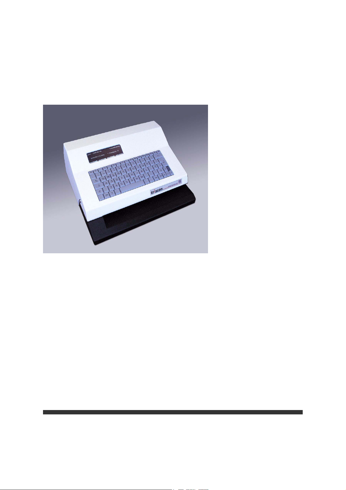
NIC2-2
Network ID Camera
Page 3

PLEASE NOTE
The information contained herein is based on the experience and knowledge rela-
ting to the subject matter gained by Triacon prior to publication.
No patent license is granted by this information.
Triacon reserves the right to change this information without notice, and makes no
warranty, expressed or implied, with respect to this information. Triacon shall not be
liable for any loss or damage, including consequential or special damages, resulting
from the use of this information, even if loss or damage is caused by Triacon's neg-
ligence or other fault.
© Triacon AB, Sweden 2003
Page 4

Page 5

NIC2-2 · Network ID Camera Publication no. 201102
Contents
1 General information 1
1.1 ESD 1
1.1.1 Overview .....................................................................................................1
1.1.2 Awareness ..................................................................................................1
1.1.3 Action ..........................................................................................................1
1.1.4 Every day ....................................................................................................1
1.1.5 During maintenance.................................................................................... 2
1.2 Safety precautions 2
1.3 Specification 2
1.4 Service tools 3
2 Physical connection 5
2.1 The HOST connector 5
2.2 The AUX connectors 5
2.3 The NET Connector 6
3 Theory guide 9
3.1 Block diagram 9
3.2 Description of functions 9
3.2.1 Power supply system .................................................................................. 9
3.2.2 CPU board ..................................................................................................9
3.2.3 Switch On / Initialize Procedure................................................................ 11
3.2.4 Opening sequence.................................................................................... 12
3.2.5 Keyboard...................................................................................................13
3.2.6 Operator display........................................................................................ 13
3.2.7 Exposure unit. ...........................................................................................13
3.2.8 Opening mechanism .................................................................................14
3.2.9 Cassette cover plate sub-assembly. ......................................................... 15
4 Disassembly/Assembly 17
Triacon AB Sweden i September 2003
Page 6

Publication no. 201102 NIC2-2 · Network ID Camera
4.1 The opening mechanism 17
4.1.1 Disassembly..............................................................................................17
4.1.2 Assembly...................................................................................................18
4.2 Replacing the power supply 19
4.3 Replacing the sealing strips 20
4.4 Replacing the Main Board 21
4.5 Replacing the Keyboard 23
4.5.1 Keyboard test ............................................................................................23
4.6 Replacing the Operator display 24
5 Diagnostic 25
5.1 Sensor adjustment 31
5.2 Adjusting the exposure unit 32
5.3 Checking if an optical switch board works 33
5.4 Checking if the light sensor works 33
5.5 Checking if a motor works 34
6 Maintenance 35
6.1 Lubrication 35
7 Built in diagnostic software 37
7.1 Test functions 37
7.2 Serial Analyser 39
7.3 System logger 39
September 2003 ii Triacon AB Sweden
Page 7

NIC2-2 · Network ID Camera Publication no. 201102
1. General information
1.1 ESD
CAUTION
!
This equipment includes parts and assemblies sensitive to damage from electrostatic discharge. Use caution to prevent damage during all service procedures..
1.1.1 Overview
Electrostatic discharge (ESD) is a primary source of
• Product downtime
• Lost productivity
•Costly repair
While we cannot feel a static charge of less than 3,500 volts, as few as 30 volts can damage
or destroy essential component in the electronic equipment. As technology advance, these
components will be even more vulnerable to ESD destruction.
Therefore, to maintain and increase productivity and profitability, you must observe ESD
guidelines.
Effective ESD control requires the following things.
1.1.2 Awareness
Everyone in your organization should be aware of ESD because partial ESD control is no
ESD control at all.
Everyone needs to remember that:
• ESD is a primary source of equipment failures and intermittent malfunctions.
• ESD affects productivity and profitability
• ESD can be controlled
1.1.3 Action
Everyone from senior management to be evening security crew must observe ESD guidelines.
• If you repair and maintain electronic equipment, always wear grounding straps and work
at ESD protected sites.
• If you work around electronic equipment, keep static generators like plastic trash bags
away from sensitive components.
• Observe ESD guidelines every day. (See the following sections for special tips).
• Remember, effective ESD control is everyone's responsibility.
1.1.4 Every day
• Keep trash away from static-sensitive equipment. Plastic materials, such as plastic foam
cups, generate the static electricity that damages or destroys electronic components.
• Look at the label. Static-sensitive components are marked with bright graphic labels.
Follow the label directions.
Triacon AB Sweden 1 September 2003
Page 8

Publication no. 201102 NIC2-2 · Network ID Camera
• Spray the carpet. ESD that is generated when you walk over carpet is a major cause of
component destruction. In some cases, especially in low-humidity environments, you
may need to periodically spray the carpets with an anti static spray that is available at
local stores.
1.1.5 During maintenance
• Wear a ground strap when you work with static-sensitive components. Always make
certain that the clip is attached to a properly grounded, unpainted surface.
• Use a portable ground mat if you cannot repair components at an ESD protected workstation.
• Use protective packaging when you transport components from one area to another.
Transparent antistatic bags, available from a variety of manufacturers, shield the components from future damage.
1.2 Safety precautions
• Do not operate or repair the ID camera without proper accessories. Add all COVERS
before use to prevent mechanical hazards and electrical shock.
• Do not use a damaged POWER CORD. The damaged CORD can cause malfunctions
and current leakage or electrical shock.
• If there are any abnormal smell or smoke during operation, de-energize the ID camera
immediately and contact authorized personnel for support.
• Do not operate the ID camera in unsafe locations such as outdoors or in wet places. Do
not allow liquids, gaseous or solid-state materials to enter the ID camera.
• When doing electrical measurements, use an isolation transformer or leakage current
detector in the power line to avoid an electrical shock.
• Double pole/neutral fusing. For continued protection against risk of fire, replace only
with same type and rating of fuse.
• Use only original parts from the Parts List to repair the ID camera.
Make sure that the requirements of UL 122 - Splice and Connection - paragraph 13.10
and EN 60 950, section 4.39 are observed. When replacing AC primary components,
such as wires, sockets or capacitors, wrap the end of the wire completely around the terminal before soldering.
1.3 Specification
Electrical supply: 115 -230 VAC, 50/60 Hz
Power consumption: 25W, max 50W
Mains fuse: 2x1 AT
Dimension: 392 x 352 x 153 mm
Weight: 12,6kg
Operating temperature: 10° - 40° C
Humidity: 20 - 85 % RH non-condensing
Approvals: EN50082, EN550022, EN61000-3-2, EN61000-3-3, EN 60950,
UL 1950 Third Edition, CAN/CSA C22.2 No. 950-95 Third Edition. FCC class B.
September 2003 2 Triacon AB Sweden
Page 9

NIC2-2 · Network ID Camera Publication no. 201102
1.4 Service tools
Use the following tools to repair a Network ID camera:
• Philip Screw Driver size PH2
• TORX Screw Driver size 10
• TORX Screw Driver size 20
• Socket head cap screwdriver 2.0 mm
• Box socket wrench 8.0 mm
• Digital Multimeter:Voltage 5 to 24V
• Resistance 0 to 100 ohm
• GluePrimer, Loctite 770 Polyolefin
• Glue, Loctite 406 Cyanoacrylate
• Nut retentionLoctite 243
To update the firmware or upload or download set-up, computer equipment is needed:
Service Computer: 100% IBM compatible
Hard disk
VGA Monitor display
1 RS 232 Serial Interface
CD Drive or Internet connection
1 9pin male-female Serial Interface Cable
Service Software: NIC Setup Manager. This programme is needed to upgrade the firm-
ware and to upload and download the set-up. The software can be
downloaded from Triacon's homepage. It is also distributen on a CD
ROM disk for a minor administration cost.
Triacon AB Sweden 3 September 2003
Page 10

Publication no. 201102 NIC2-2 · Network ID Camera
Blank Page
September 2003 4 Triacon AB Sweden
Page 11
NIC2-2 · Network ID Camera Publication no. 201102
2. Physical connection
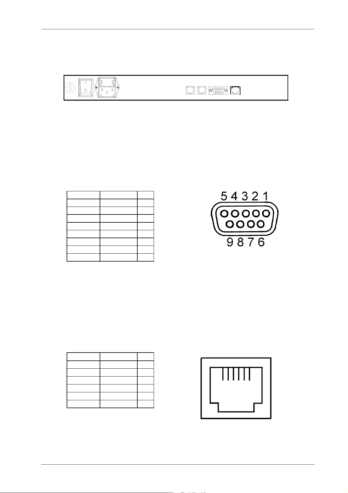
On the back of the Network ID Camera there are four connectors for communication.
2 AUX 1 HOST NET
2.1 The HOST connector
This connector is a female 9-pin DB9 connector. Its pinout is designed with the 9-pin connector used on PC compatibles in mind. If the Network ID Camera is to be connected to a
PC compatible computer a pin-to-pin cable with a male connector on one end and a female
connector on the other end can be used. If it will be connected to another host computer the
following pin description can be used to make your own cable. Note that the name of the
pins mentioned is what the pin should be connected to. Thus RxD is really an output from
the camera. .
Name Direction No
DCD Out 1
RxD Out 2
TxD In 3
DTR In 4
GND 5
DSR Out 6
RTS In 7
CTS Out 8
Note that the Network ID Camera do not need any handshake signals to work. It sends out
all handshake signals to the host computer but ignores any handshake input. If your host
computer also ignores the handshake signals you will only need to connect the ground (pin
5) and the TxD (pin 3).
2.2 The AUX connectors
These connectors are of type RJ12 connectors. Note that the name of the pins mentioned
is what the pin should be connected to. Thus RxD is really an output from the camera. .
1 2 3 4 5 6
Name Direction No
RxD Out 1
TxD In 2
CTS Out 3
RTS In 4
GND 5
+VDC Out 6
+VDC is a high level signal out. This signal is intended for setting DCD and DSR if needed.
Triacon AB Sweden 5 September 2003
Page 12

Publication no. 201102 NIC2-2 · Network ID Camera
To adapt the AUX connentors to 9 pin DB9 PC compatible RS232 interface a adapter cable
is required
RJ12 9 pin female
1 2
2 3
3 8
4 7
5 5
6 1
6
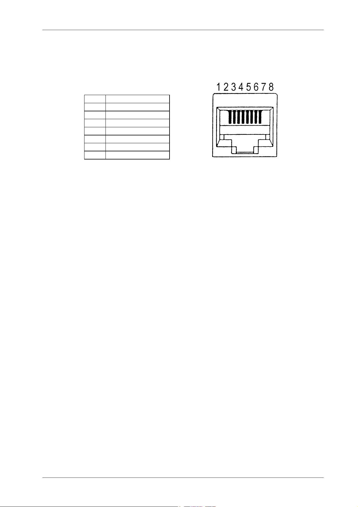
2.3 The NET Connector
This connector carries one RS422/485 (software selectable) and one RS485-only communication channel. When using this connector for patient data download only the RS422/485
channel is used in RS422 mode. This channel is called the HOST-RS422 below.
The connector is of the type RJ-45. It was selected because there are a lot of cable and connector material available for this kind of connector as it is also used to build LAN networks
of type 10Base-T for personal computers. Normally this way is used to connect cameras to
a host computer is when one host computer is connected to more then one camera but it
may also be used if the distance between the host computer and camera is too long for
RS232.
Next section will describe how to build an RS422 network using commonly available materials made for 10Base-T networks. Below follows the specification of the NET connector that
may be needed if other material is used.
The pinout of the NET connector.
Pin Used as: Name
1 + for the HOST RS422 output Network Pair
2 - for the HOST RS422 output Network Pair
3 GND Network ground
4 + for the HOST RS422 input and RS485
bi-directional
5 - for the HOST RS422 input and RS485
bi-directional
6 GND Network ground
7 - external equipment RS485 External equipment pair
8 + external equipment RS485 External equipment pair
Network Pair
Network Pair
September 2003 6 Triacon AB Sweden
Page 13
NIC2-2 · Network ID Camera Publication no. 201102
There is a standard colour
scheme used by most (all)
connector and cable
manufacturers, base
This is a picture with pin numbers of
the female MOD8 connector found
at the back of the camera.
colour first then the stripe
colour.
1 White/Orange
2 Orange/White
3 White/Green
4 Blue/White
5 White/Blue
6 Green/White
7 White/Brown
8 Brown/White
Regardless of what is connected where, shielded connectors, patch cables and installation
cables should be used. The cable should be a "4 pair STP" category 3 or 5. Unfortunately
there does not seem to be any standard name for this equipment that can be referred to
when buying. The only common description seems to be that it is the same equipment as is
used for 10Base-T networks.
Triacon AB Sweden 7 September 2003
Page 14

Publication no. 201102 NIC2-2 · Network ID Camera
Blank Page
September 2003 8 Triacon AB Sweden
Page 15
NIC2-2 · Network ID Camera Publication no. 201102
3. Theory guide
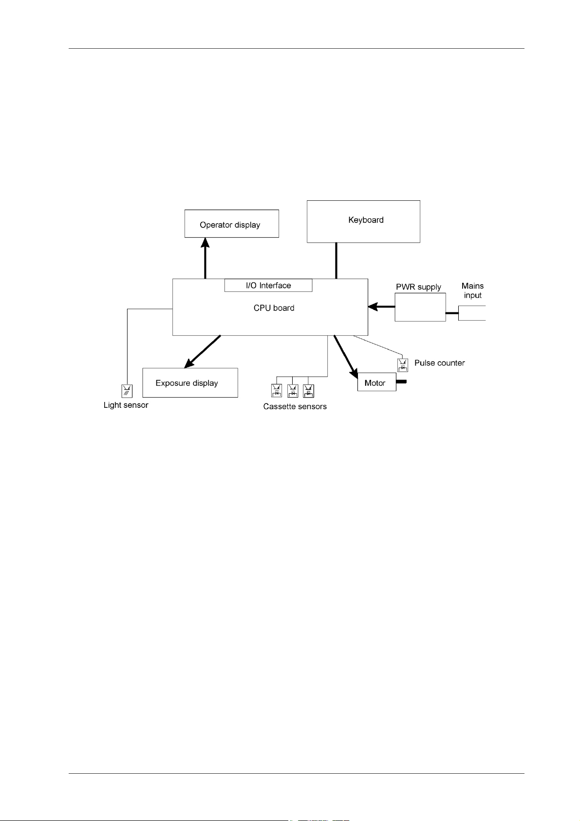
3.1 Block diagram
All functions of the ID camera are controlled by the microcontroller on the CPU board.
The controlling firmware is stored in a 512K FLASH memory. All inputs, outputs and drivers
for the motor are located on the CPU board. The CPU board is connected to the operator
display, exposure display, keyboard and motor sensors. All connectors for external communication are located on the CPU board..
Block diagram of Network ID Camera
3.2 Description of functions
3.2.1 Power supply system
The power system of the ID camera consists of:
• A mains input module featuring a mains cord connector built together with a mains filter
and a fuse holder.
• A mains switch mounted at the back of the camera.
• A switched power supply delivering 24V/50W.
3.2.2 CPU board
The CPU board features:
• A 16 bit microcontroller. Motorola 68HC16.
• 512K of FLASH memory where the program is stored. 16K is used to store a bootstrap
program used to download the main program and 16K is used to store the set-up of the
camera.
• 256K battery backed-up RAM memory used to store data while operating.
• One RTS.
• Three switched power converters for converting the 24V supply voltage to 5V, 12V and 12V.
Triacon AB Sweden 9 September 2003
Page 16

Publication no. 201102 NIC2-2 · Network ID Camera
• Two high voltage converters, called inverter, for the background light of the operatorand exposure display. These are a separate boards mounted on top of the CPU board
on the left side
• Two RS232 serial ports.
• One RS232/RS422 serial port.
The CPU board is controlling all functions of the
ID camera. The following connectors are locat-
JP4
JP4
ed on the board.
JP1 External RJ12 connector. RS232.
JP14
JP13
JP7 JP6
JP15
JP1
JP2
JP3
JP12
JP16
JP11
JP17
JP19
JP2 External9 pin female D-SUM.
RS232.
JP3 External RJ45 connector. RS232/
RS422
JP4 24VDC power.
JP5 Motor.
JP6 Exposure display
JP7 Operator display.
JP8 Power to the back-light of the oper-
ator display.
JP9 Power to the back-light of the expo-
sure display.
JP10 Left opto sensor board
JP11 Middle opto sensor board.
JP12 A connector to the background de-
bug channel of the Motorola
68HC16 CPU. Only used during
production.
JP13 Keyboard adapter board.
JP10
JP14 Keyboard adapter board.
JP15 External RJ12 connector. RS232.
JP16 Right opto sensor board.
JP17 Not used.
JP18 Jumpers for RJ45 connector.
JP19 Light sensor.
JP8 JP9
September 2003 10 Triacon AB Sweden
Page 17

NIC2-2 · Network ID Camera Publication no. 201102
3.2.3 Switch On / Initialize Procedure
Camera status: Mechanic position of the
Start
Initialize hardware
Ch eck i f P
key is
pressed
Run motor to the left until not
moving for 0. 3 sec. Set position to 0.
Move motor six step to the
right.
Faild to do
this.
Run motor to the left until not
moving for 0. 3 sec.
Position
>-3 and <3
Yes
Yes
No
Download
procedure
The microprocessor starts the initialization
routine. First while still executing the bootstrap program, the P key is checked. If
pressed the download procedure will be started.
If not pressed the bootstrap routine will call
the main program.
The main program initializes all hardware resources on the CPU board as well as the operator- and exposure display.
The main program checks if the set-up memory is valid by calculating a check sum. If the
check sum does not match the stored value
the set-up memory is erased.
The opening unit is run to calibrate the mechanism to find out the left position of the movement area.
The contrast of the exposure display is set.
If calibration of opening mechanism as well as
for contrast of exposure display is successful
the main picture is displayed and the camera
is ready for operation.
carriage is not known. Camera is energized.
Set position to 0
Set exposure display contrast
Contrast
within
limits.
End Failed
No
Triacon AB Sweden 11 September 2003
Page 18

Publication no. 201102 NIC2-2 · Network ID Camera
3.2.4 Opening sequence
Start
Left and right sensors are on
and middle sensor is off.
Run motor at low speed.
Sensor status
changes
No
No
No
Unlocking
position
reached
Yes
Run motor at high speed.
Open
position
reached
Yes
Stop mot or
Make an exposure
Run motor backwards at high
speed.
Position 10
reached
Start flashing the operat or
display
Run motor backwards at low
speed until not moving for
0.3sec
Yes
Camera status: The opening carriage is positioned in its
left position.
The sequence is initialized when the left and right cassette
sensors are activated while the middle sensor is not.
First the motor is run to the right at a slow speed until the
finger of the carriage has entered the hole of the cassette
lid and unlocked the lid. At that point the speed of the motor
is increased to full speed.
The motor is run at full speed until the position where the lid
is considered opened. At this position the motor is stopped.
This position can be changed in the setup of the camera.
The exposure is made by switching on the background light
of the exposure display. When the exposure is done the
background light is switched off.
The motor is now run at full speed towards it's left position
until position 10 is reached. At that position the operator
display starts flashing and the speed is slowed down, The
motor run until no movement is detected for 0.3 seconds.
The motor is now considered being stopped at its left position. The position is now checked. If it is not within -3 to 3 it
was not able to reach its left parking position and an error
message is generated. If within this range the position is set
to 0 and the exposure cycle is finished.
The right and left sensor must both be off before the operator display stops flashing and a new exposure can be
made.
During all operations it is checked that the motor is rotating.
If no pulses are read from the pulse counter for 0.3s the motor is considered stopped by force and the motor is
switched off and an error message generated.
Position > -3
and <3
Set position to 0
Wait for left and right seonsors
to become inactive
Stop flashing the operator
display
End
No
Yes
Fail
September 2003 12 Triacon AB Sweden
Page 19

NIC2-2 · Network ID Camera Publication no. 201102
3.2.5 Keyboard
The keyboard is a standard 84 keyboard.
The keyboard layout may be changed by replacing the whole keyboard and selecting the
appropriate language in the firmware.
3.2.6 Operator display.
The operator display is a 240 pixel wide and 64 pixel high graphic liquid crystal display (LCD)
display with cold cathode fluorescent lamp back-light. The LCD is controlled by the microprocessor on the CPU board. All characters are generated by the microprocessor and this
allows the Network ID Camera to show any character on the display in any size. Current
firmware provides 256 - 32 characters according to ISO 8859-1 in three sizes.
The back-light is driven by a high voltage and the generator (called inverter) that is located
as a small separate board on the CPU board. The life-length of the back-light is between
10,000 and 15,000 hours. Life-length is the number of hours the light can be on until the intensity has decreased to half of the initial intensity. To extend the life length of the back-light
it will be switched off automatically when the camera has not been used for an hour and will
be switched on again as soon as a key on the keyboard is hit.
The LCD display is protected by a acrylic shield that can be replaced separately. It is not a
part of the LCD display but inserted between the LCD unit and the case.
3.2.7 Exposure unit.
The main parts of the exposure unit are the display, the lens and a mirror
The display is used to generate the picture that will be printed on the film. It is a 240 pixel
wide and 64 pixel high graphic liquid crystal display (LCD) display with cold cathode fluorescent lamp back-light, same type as the operator display. It is fully graphical which means
that any picture can be generated, the picture can be mirrored in any direction and the information can be printed either white on black or black on white.
The lens is a specially made for this camera. Both the sides of it has a convex lens and the
least convex side should face the display. The size of the picture on the film can be adjusted
by moving the lens backwards or forwards. This is though not recommended except in special cases. On the market there are very few cassettes with a window which is shorter then
normal. For example there exists a mammography cassette where the window is located on
the short side and not on the long which is normal. Because of this there is no room to open
the window fully, instead the window is made about 25% shorter. To be able to use this cassette with the Network ID Camera the lens has to be moved. It may also be necessary to put
Triacon AB Sweden 13 September 2003
Page 20

Publication no. 201102 NIC2-2 · Network ID Camera
the lens backwards to decrease the size of the picture even more. When shipped the size
and position of the picture is set to work with Kodak cassettes or equivalent.
The mirror is a surface plated mirror. It should not be polished as this will destroy the silver
layer and affect the quality of the picture. The mirror can be moved backwards and forwards
and tilted. It is important to set the angle correct as if the angle is not 45 degrees the picture
will be a trapezoid instead of a rectangle.
3.2.8 Opening mechanism
The opening mechanism consists of a motor driving a screw. This screws drives a carriage
which glides on a shaft. The carriage has a finger that unlocks the lid and opens the lid. To
do this the finger has to move up and down and this is achieved by a cam on the back of the
opening mechanism assembly and a ball-bearing mounted on the back of the carriage which
rolls on this cam. On the left side of the opening mechanism assembly there is a code disk
mounted on the driving screw and a optical switch which is used as a pulse counter.
The opening sequence is described in chapter 2.2.3 and will not be repeated here.
The optical board mounted on the left side of the assembly can be sledded backwards and
forwards to adjust the cassette sensing point. This adjustment is described in the Diagnostic
chapter. There is no need for any adjustment for the pulse counter.
The only adjustment on the opening mechanism is the position on the cam. The cam can be
sledded sidewise to adjust the position when the finger goes down in the lid to unlock it. If
this position is set too far to the right the lid may not lock when closing the lid. If the position
is set too far to the left the finger may hit the edge of the window. When doing the adjustment
it is a good idea to gently press the finger down to get the play in its down position and then
move the carriage manually by rotating the screw. Also the setting should be checked with
all cassette types used. When the setting is correct, rotate the screw by hand through the
phase where the finger goes down and while doing so, push the finger gently upwards to get
the play in the upper position. This should be done to check that the carriage can in no way
hit the exposure unit.
In the finger there is a pin. There are two kinds of lids on the cassette types the Network ID
Camera can work with. One is made of metal with a metal locking mechanism. This lid is
used on all or many of Kodak's, Fuji's and Dupont's cassettes. The other is made of plastic
with a plastic locking mechanism. The plastic lid is more then 1mm thicker then the metal lid
which means that the finger has to reach 1mm deeper when the plastic lid is used. The
strength of the spring is such that when the metal lid with its metal locking mechanism the
locking mechanism will be able to push the pin upwards but when the plastic lid is used with
September 2003 14 Triacon AB Sweden
Page 21

NIC2-2 · Network ID Camera Publication no. 201102
its weaker locking mechanism the pin will not be pushed upwards and thus will be able to
unlock the deeper locking mechanism.
3.2.9 Cassette cover plate sub-assembly.
The cassette cover-plate has three sensors mounted which are used to indicate that the cassette is in position for marking. The left and right sensor are touching the front edge of the
cassette while the middle sensor should enter a hole in the cassette. There is a special test
mode in the firmware that will display the status of the sensors. The test mode and the adjustment of the sensors are described in a section in the diagnostic chapter.
Triacon AB Sweden 15 September 2003
Page 22

Publication no. 201102 NIC2-2 · Network ID Camera
Blank page
September 2003 16 Triacon AB Sweden
Page 23

NIC2-2 · Network ID Camera Publication no. 201102
4. Disassembly/Assembly
The camera is opened by removing two big screws, one on each side, and then flip the case
open by pulling the front of the white case upwards.
To get a better view of the opening mechanism and the exposure unit the upper baffle can
be removed by loosening (not removing) the two screws (A) at the front and then pull upwards at the front of the baffle.
4.1 The opening mechanism
4.1.1 Disassembly
• Remove the two cables at the back of the exposure unit.
• Check the position of the exposure unit. It can be sledded sidewise and it will be easier
to put it back if we know where it was before. Put a piece of tape on the bottom plate or
measure the distance between the left edge of the bottom plate and the exposure unit.
• Remove the two screws that holds the exposure unit to the bottom plate of the camera.
• Remove the exposure unit by pulling the back of it upwards/slightly backwards and let it
fold until the front is released from the holder.
• Check the position of the optical switch board. It can be sledded sidewise and it will be
easier to put it back if is known where it was before. Unscrew and remove the optical
switch board circuit (A) board to the left of the motor assembly. Let it hang loose in its
cables.
Triacon AB Sweden 17 September 2003
Page 24

Publication no. 201102 NIC2-2 · Network ID Camera
• Move the carriage (E) to the right by turning the lead screw so that the ball bearing at the
back of the carriage gets free and the carriage later can be lifted right upwards without
any hindrance.
• Remove the code disk (B), the washer and the distance at the left end of the lead screw
by unscrewing the nut (C) on the lead screw. To do this the lead screw has to be held inplace by inserting a socket head cap screwdriver into the screw (D) that holds the lead
screw to the motor shaft.
• Remove the two E-rings (M). Note that the right one is fixed with a screw.
• Slide the shaft (F) sidewise and remove the stopper (O) and the stroke compressor (P).
Pull the shaft out.
• Now the carriage can be lifted straight upwards and put aside.
• Remove the lead screw (G) by first un-tighten the screw (D) that holds the lead screw to
the motor shaft and then loosen the two screws that hold the motor. Separate the motor
from the lead screw by pulling the motor to the right. The lead screw can now be removed. NOTE! The ball bearing has a given position and should not be moved unless it is
to be exchanged.
• The carriage itself should not be disassembled. The two plain bearings (K) are onetime-only and can not be removed and inserted again.
4.1.2 Assembly
• Slide the lead screw (G) back in the ball bearing (H) and then but the motor back. Push
the lead screw (G) over the motor shaft while position the motor. Fix the motor.
• Position the lead screw sideways against the ball bearing and fix it with the socket head
cap screw (D). It is important that the ball bearing (H) is at its given position, if it has
been moved it has to be adjusted, see point 7 below.
• Put the carriage (E) back over the nut (L) on the lead screw.
• Put the shaft (F) that holds the carriage back. Make sure that thestroke compressor and
the stopper are mounted in right order.
• Put on the E-rings (M) and fix the right E-ring with the screw.
• Put the code disk (B) back. First the 5mm thick distance should be applied, then the
code disk and finally the nut. The nut must be secured with Loctite 243 or equivalent.
• The optical switch circuit board (A) is next. It should be fastened with two screws. It
need to be calibrated but a good start is if it is put close to it's original position. Most
often the position can be seen by the marks the screws make in the board. NOTE! It is
very important to verify that the sensors goes free from on one hand the ball bearing and
the other the code disk. If not, the lead screw must be adjusted. This is done by loosen
the socket head cap screw (D) and carefully press the lead screw, including the ball
bearing, sideways.
September 2003 18 Triacon AB Sweden
Page 25

NIC2-2 · Network ID Camera Publication no. 201102
• Put the exposure unit in place. Put it in the position according to point 2 in the disassem-
bly instructions. Its position needs to be calibrated later. If point 2 was ignored make
sure that the position is not too far to the left because the carriage may hit the exposure
unit during the opening.
• Now everything is in place. Next step is to adjust the optical switch board. Please refer
to the chapter about the sensor adjustment in the diagnostic chapter.
• Next step is to adjust the position of the exposure unit. How to do this is described in he
Diagnostics chapter.
4.2 Replacing the power supply
CAUTION
Remove the mains connection. When working on the
!
power supply the mains must not be connected.
Power supply
A
B
The power supply is located at the right side of the top cover
• Disconnect the connectors ’A’ and ’B’.
C
C
• Open the top cover of the power supply by removing the two screws ’C’.
D (x4)
E
• Remove the four screws ’D’ and replace the power supply.
NOTE! The two upper screws holding the power supply are grounding connectors. It is
important that these screws are correctly tightened.
Triacon AB Sweden 19 September 2003
Page 26

Publication no. 201102 NIC2-2 · Network ID Camera
• When the top cover is on its place, connect the two connectors ’A’ and ’B’ again.
• Power on the system and verify function.
NOTE! The green LED ’E’ indicates 24VDC out.
4.3 Replacing the sealing strips
• Open the top of the camera according to the description at the beginning of chapter 3.
• Remove the upper baffle by loosening (not removing) the two screws (A) at the front and
then pull upwards at the front of the baffle.
• Remove the cover (C) of the optical unit by loosen the screws (B), two at each side. If
the entire exposure unit is removed it must be adjusted after reinstallation, see chapter
4.2. NOTE! The mirror surface should NOT be exposed to any kind of physical contact.
• Remove the sealing strips (D) fixed from below on the cassette cover sheet. Make sure
that the surface is clean from old remains.
• Apply the new sealing strips. We recommend that Loctite 406 glue together with Loctite
770 primer is used.
• Reinstall the cover (C). If necessary, clean carefully the display window and the lens
using a soft piece of rug and alcohol. NOTE! Do not clean the mirror.
• Put the upper baffle in place and tighten the screws (A).
• Close the top of the camera.
• Done.
September 2003 20 Triacon AB Sweden
Page 27

NIC2-2 · Network ID Camera Publication no. 201102
4.4 Replacing the Main Board
Upper baffle
CPU Board
The CPU board is located inside the unit - rear side of the bottom plate.
If it is possible, it is recommended to save the current set-up in the unit before exchanging
the main board. To do so, please refer to Installation and Setup Manual chapter 3.8 'Remote
Control'.
• Remove the mains connection.
• Open the top of the camera and remove the upper baffle.
• To be able to exchange the CPU board it is necessary to remove the exposure unit.
A
D
Mark
Before doing that, make a mark of the exposure units position using a sharp tool as
shown in picture above. This will help you to reposition the unit after the CPU board is
replaced.
B
D
C
• Disconnect the two cables ’A’ and ’B’.
Triacon AB Sweden 21 September 2003
Page 28

Publication no. 201102 NIC2-2 · Network ID Camera
• Remove the two screws ’D’ and gently pull the exposure unit out. Note that cable ’C’ is
going to the CPU board and has to be disconnected before removing the exposure unit
completely.
CAUTION
The MicroMatch connectors (red ones) have a small polarizing pin on left
!
side. Loosen the connector carefully to avoid damage on these pins.
Exposure
display
Back ground light
operators display
Back ground light
exposure display
Opto sensor left Light sensor
• Replace the CPU board. Eight Torx M3 x 6 screws are holding the board.
• When the new board is installed, make sure all eight screws are tightened and the connectors are properly inserted.
• Reinstall the exposure unit by connecting the light sensor connector as step one.
• Put the exposur unit gently on place and adjust it sidewise according to the mark made.
• Tighten the screws and connect the two connectors ’A’ and ’B’.
Operator
display
Opto sensor middle
Keyboard
24VDC in
Motor
Opto sensor right
• Put the upper baffle back and close the cover.
• Power on the unit and verify that actual firmware version is loaded. This is done by pressing SHIFT+F4 from the main window and read the version at the top right corner of the
display.
• If a update of the firmware version is required, please refer to Installation and Setup
Manual chapter 4 'Upgrading the firmware'.
• Download the previously saved set-up, please refer to Installation and Setup Manual
chapter 3.8 'Remote Control'.
September 2003 22 Triacon AB Sweden
Page 29

NIC2-2 · Network ID Camera Publication no. 201102
4.5 Replacing the Keyboard
• Open the top of the camera.
B
C (x4)
• Locate the small adapter board 'A' and disconnect the two MicroMatch connectors (red
ones). Note that the have a small polarizing pin on left side. Loosen the connector carefully to avoid damage on these pins.
• Disconnect the two flexi strip, coming from the keyboard, by gently pulling them out.
• Remove the keyboard support 'B' which is secured by four screws 'C'.
• Replace the keyboard.
Make sure the keyboard is correct positioned before tighten the screws 'C'. Best way to
do this is to verify that there is some space between the edges of the keyboard and the
top cover, ref. 'D'.
A
D (x4)
• Connect all cables and connectors.
• Close the top cover and secure it.
4.5.1 Keyboard test
A built in test program can be used for test of the keyboard.
• Holed down the P-key while power on the unit.
• Press Ctrl+T and select Keyboard test by pressing the M1-key, a graphic image of the
keyboard appear on the display. Now, pressing down one key will "fill" corresponding
position on the graphic image.
• Verify the keyboard by pressing each and one of the keys.
When done, switch the unit off and on again to start it up in normal mode.
Triacon AB Sweden 23 September 2003
Page 30

Publication no. 201102 NIC2-2 · Network ID Camera
4.6 Replacing the Operator display
• Power down the Camera before starting this work.
• Open the top of the camera.
Operator
Display
C (x4)
A
B
• Locate the operator display.
• Disconnect the data cable ’A’ and the back ground light cable ’B’.
CAUTION
The background light is supplied with high voltage. This voltage is gene-
!
rated by a inverter located on the main board. Make sure the unit is powered down before disconnecting the background light.
• The display is hold by the four screws ’C’. Remove these screws and take out the display.
• Insert the new display and tighten the screws.
• Connect the operator display cable ’A’ and the background light cable ’B’.
• Close the cover and power up the unit.
• Verify function.
September 2003 24 Triacon AB Sweden
Page 31

NIC2-2 · Network ID Camera Publication no. 201102
5. Diagnostic
Diagnastic
The c amera appears
dead. Nothing is
written on the display.
Startup problems.
Page 26
Something is written
on the display.
Unexpected response
from the keyboard.
Cassette problems
when marking a film.
Nothing is printed on
the f ilm .
The camera faild to
communicate.
Initialis ation problem s .
Keyboard problems.
Cassette opening problems.
Marking problems.
Communic ation problems.
Page 27
Page 28
Page 29
Page 30
Please refer to the
Network Manual.
Triacon AB Sweden 25 September 2003
Page 32

Publication no. 201102 NIC2-2 · Network ID Camera
Startup problems
Startup problems
Background
light of the
operator
disp lay is lit?
Check that mains cord
is properly connected.
Chec k
primary
fuses.
Yes
Broken
Hold the P-key down
w hile t he c amer a is
switched off and on.
Something
written on
the display?
LED on
CPU board
is flashing?
Replace fus es
Yes
Yes
The message is probably about program load.
The firmware in the c amera has been eras ed or
a firmware update has failed.
- Reload the firmware.
The CPU board is operating properly.
- Chec k the cables to the operator display.
- Replace the display.
CPU board error.
- Chec k the cable to the expos ure display.
- Replac e CPU board.
Not broken
Check 24V
on the
Power
supply.
Fail
Disconnect
24V from CPU
board and
check again.
Fail
Chec k
primary input
on power
supply..
Fail
Verify that 24V is connected to the
OK
CPU bo ard. If it s t ill not w or k , r epla c e
the CPU board.
OK
Short circuit of 24V on CPU board.
Replace the CPU board.
OK
Power supply broken. Replac e power
supply.
Main f ilt er or p ow er s w it c h or the
wires between main filter and power
supply broken.
September 2003 26 Triacon AB Sweden
Page 33

NIC2-2 · Network ID Camera Publication no. 201102
Initialation problem
Init ial prob lems
The text
"Program
load" ap pear
on the disply
"Error: T esting
Contrast"
app ear on t he
display.
"Faild to
calibrat e opening
mechanism"
app ear on t he
display.
Yes
The firmware has been
erased or a firmware
update has faild. Reload
the firmware.
Yes
No or bad signal from the light sensor.
- Check cable between the sensor and the CPU board.
- Verify function of the light sensor, ref. chapter 5.4.
- Replace CPU board.
Yes
Can the
motor be
turned
manually?
No
Yes
Move the carriage about 5 cm from left end
position by manually rotate the motor sc rew.
Switch on the main power and notis any
movements of the carriage.
Release the motor and try again. If the motor
can not be released, the mechanics has to be
investigated because something is blocking the
motor.
The motor
runs but only
in one
direction.
Encoder problems.
Yes
- Check cable betw een left sensor and CPU board.
- Verify function of left sensor board, ref. c hapter 5.3
- Replace the CPU board.
No pow er to the moter.
- Check cable between motor and CPU board.
- Verify function of the motor, ref. chapter 5.5.
- Replace CPU board.
Triacon AB Sweden 27 September 2003
Page 34

Publication no. 201102 NIC2-2 · Network ID Camera
Keyboard problem
Keyboard problems
Text for function
key s are changed
while SHIFT
key is pressed.
Does the
LED on CP U
board flash?
Yes
Yes
The program does not work. If this happens
w hen the c am era is jus t s tar t ed s o mething is
wrong with the program. Erase the setup
and/or reload the firmware.
Some of the keys are constantly pressed.
- Check if keys are stucked.
- Exchange keyboard.
No connection between keyboard and CPU board.
Check the c ables betw een the CPU board and the
keyboard. Note the two flexistrips comming from the
keyboard to the adapter board.
September 2003 28 Triacon AB Sweden
Page 35

NIC2-2 · Network ID Camera Publication no. 201102
Opening problem
Opening problems
Carriage get s
stuck at left
end.
Carriage get s
stuck at right
end.
Carriage get s
stuck when
unlocking lid.
Yes
Yes
Yes
Goto initial pr oblems f lo w c h ar t .
There may be two reason. Either the
opening leghth has been changed in the
camera setup or the pulse counter is
defect. To set the opening length, see
chapter 7.1. To verify the pulse
counter, see chapter 5.3.
Run the camera manually through the
unlocking by rotating the lead screw
by hand to find what stops it.
This happens because the right or left
Camera only
allows one
marking.
Yes
cassete sensor does not fall back to
its inactive position. Enter camera
setup, select sensor adjustment and
verify/adjust the sensors.
Goto initial pr oblems f lo w c h ar t .
Triacon AB Sweden 29 September 2003
Page 36

Publication no. 201102 NIC2-2 · Network ID Camera
Marking problems
Film is not marked
No sound
when
insert ing a
cassette.
Yes
Open the c amera and remove
upper baffle to view the
exposure display. Insert a
cassette.
A p icture is
shown on the
exposure
display
Yes
Make a second exposure and
check the lid of the cassettet
No
The cassette sensors are not
correct adjusted. See chapter 5.1.
No
Background
light of the
expos ure
disp lay is lit
Problems with cabling or the light
sensor. Check the 20pin data cable.
Check func tion of the light sensor,
see c hapter 5. 4.
Yes
Either the display or the CPU board is
broken. Switch off the c amera and swap
No
the background light c onnectors between
the operator- and exposure display. Power
on the camera and check w ether
background light of the exposure display.
Background
light of the
expos ure
disp lay is lit
No
Yes
Ther is problems unlocking the lid.
Lid is
op ened.
No
Run the camera manually by
rotating the lead screw to see that
the pin of the carriage either does
not hit th ehole into the lid or if it
fails to unlock it. If the cassette is
not a very special kind th eproblem
Yes
is solved by moving the cam
sidewise.
Something is bloc king the light from
the exposure display. Check the lens
and the mirror. Check the adjustment
of the exposure unit, see chapter 5.2.
Background light of the exposure
display is broken. Exchange the
exposure display.
Inverter on the CPU board is broken.
Exchange the CPU board.
September 2003 30 Triacon AB Sweden
Page 37

NIC2-2 · Network ID Camera Publication no. 201102
5.1 Sensor adjustment
Middle
Left
The left and right sensors senses the front of the cassette. When the cassette is inserted
well enough the opening cycle may start. The middle sensor is a pin that should enter a hole
in the front side of the cassette. If the cassette is not well pushed towards the left side of the
opening of the cassette the pin will hit beside the hole and the middle sensor will be pushed
by the cassette and by detecting this the camera knows that the cassette is not properly inserted.
To adjust the sensors, enter the set-up mode of the camera. Select Sensor adjustment. Here
a picture is shown showing the status of the three sensors. Note that this picture is also
shown on the exposure display so if the baffle over the exposure unit is removed there is no
need to look at the operator display to do the adjustment.
When no cassette is inserted all sensors should show OFF. When a cassette is inserted in
marking position the left and right sensor should show ON and the middle sensor should
show OFF.
Right
Adjusting a sensor is made by loosening the two screws that holds the corresponding optical switch board and then slide the board until it switches between ON and OFF in the appropriate position.
The left sensor should switch to ON when there is about 1.5 mm until the cassette is fully
inserted.
The right sensor should switch to ON when there is about 1.5 mm until the cassette is fully
inserted ,but this adjustment is not as critical as the left sensor. What is critical is that when
both the left and right sensor are both switching to on the hole of the lid in the cassette must
be in a position where the pin of the opening carriage will enter the hole. This means that
the setting of the left sensor is quite critical. 1 mm here will mean 1 mm in the position of the
hole. The right sensor is not so critical,1 mm in her will mean about 1/10 of a mm in the position of the hole.
The middle sensor should be adjusted to switch to ON in the middle of its movement. Take
a cassette and insert it but keep it a few centimeters from the left side of the cassette bed
so the pin of the middle sensor does not hit the hole in the cassette. Move the cassette in
and out to see how much the sensor moves. Find the middle of this movement, hold the cassette there and adjust the optical switch board so it switches at this position.
When the two screws holding an optical switch board has been tightened the sensor should
be checked once more as the board may move when the screws are tightened.
Triacon AB Sweden 31 September 2003
Page 38

Publication no. 201102 NIC2-2 · Network ID Camera
5.2 Adjusting the exposure unit
This adjustment must be made if the exposure unit has been moved. First the lens has to
be adjusted. By moving the lens backward or forward the size of the picture can be changed.
This adjustment only has to be made if the lens has been moved in it's holder. Next is to
adjust the mirror and the position of the exposure unit sidewise.
As a help a frame drawn on a paper is needed. This frame should be inserted in an empty
cassette and the camera will then be made to present a corresponding frame on the exposure display which will be projected on the paper in the cassette using a special test mode
of the camera. The size of the projected frame should then be adjusted to match the frame
on the paper.
The size of the frame should be 13mm high and 64mm. You may very well make a copy of
the illustration below. Just remember to check that the size after copying is still 13 by 64 mm.
Edge of the cassette
The window of the cassette
The frame to adjust to
30mm
• Insert the paper with the frame into the cassette as illustrated above.
• Take the camera somewhere where there is not to much light.
• Open the camera and remove the baffle that covers the exposure unit by loosening (not
removing) the two screws in the front of the baffle. If the exposure unit needs to be
adjusted sidewise the two screws that holds the exposure unit to the base plate should
be un-tightened.
WARNING! By doing this you will also remove the cover that protects
you from the moving carriage when the camera is operated!
!
21mm
• Enter set-up mode/test functions. Select test picture Frame C1N.
• Insert the cassette. Press the Sift+F1/Adjust. The camera will open the cassette and
keep it open and display the test picture.
• Now make the frame displayed on the exposure display show on the paper in the cassette by tilting the mirror and maybe moving the lens.
• Next adjust the lens so that the size of the frame projected on the paper fits within the
frame on the paper. The lines of the projected frame is probably wider then the line on
the paper. They should be on or within but not outside the lines on the paper. Adjust the
position sidewise by moving the entire exposure unit if necessary. If the picture is trapezoid (sides are not parallel) can be corrected by moving the mirror backwards or forwards in the holes it is mounted in. Just loosen the screws and slide it. If the upper and
September 2003 32 Triacon AB Sweden
Page 39

NIC2-2 · Network ID Camera Publication no. 201102
lower lines are not parallel it is because the left and right side of the mirror are not adjusted properly relative to each other.
• When the projected frame is rectangular and the size is adjusted to the frame on the
paper, tighten the screws that holds the exposure unit to the base plate, tighten the
screws that holds the mirror, carefully as the mirror may tilt when doing so. Check that
the adjustment is still OK.
• Press Sift+F1/Adjust again to close the open cassette and to switch the exposure dis-
play off. Put the baffle back and tighten the screws that holds it. Close the cover of the
camera and mount the two screws that holds the cover.
• Make an exposure to make sure that everything is OK.
5.3 Checking if an optical switch board works
Three optical switch boards are used in the camera. Two have one optical switch mounted
and one have two optical switch. They are all used for the cassette sensor described in the
previous chapter but the board with two optical switch are also used for the pulse counter.
The pins in the connector of the optical switch board are used at follows.
The pin marked single are on all three optical switch boards used to detect the status of the
sensors while the pin marked double is used for the pulse counter detector.
When nothing is inserted in the gap of the optical switch the voltage between GND and the
output (Double or single) should be less then 0.5V. When something is inserted breaking
the light the voltage should be more then 3V. Note that an ordinary paper will not break the
light. The IR light will go through the paper. Best to use is a piece of metal, for example a
piece of aluminum foil. Also, check the plastic cover of the optic sensors that it is not broken.
5.4 Checking if the light sensor works
GND
+5V
Signal
Use a multimeter to messure the voltage between ”Signal” and ”GND”. The signal voltage
should be aboult 1 - 2V in normal daylight. Cover the sensor and the voltage should drop
and if the light intensity increases the voltage should rise.
Triacon AB Sweden 33 September 2003
Page 40

Publication no. 201102 NIC2-2 · Network ID Camera
5.5 Checking if a motor works
Motor
connector
This check is preformed by simply connect an external power supply to the motor.
• Power down the camera and disconnect the motor connector.
• Move the carriage to its center position about 60 cm to the right.
WARNING! To apply external voltage to the motor will cause a immediate
reaction. To avoid mechanical damages, use a 12VDC/1A supply.
!
• Connect the supply to the motor and switch it on for just a few secunds.
• If the motor is OK the carriage should move a bit.
September 2003 34 Triacon AB Sweden
Page 41

NIC2-2 · Network ID Camera Publication no. 201102
6. Maintenance
When the camera is operated in a dusty environment it may be necessary to open the camera regularly to clean out the dust.
Cleaning the outside of the camera may be done with a piece of cloth and mild soap.
NOTE! Never use strong chemicals, including alcohol or abrasive to clean the outside of the
camera.
6.1 Lubrication
No lubrication is needed inside the unit. All moving parts is self lubricated.
Triacon AB Sweden 35 September 2003
Page 42

Publication no. 201102 NIC2-2 · Network ID Camera
Blank Page
September 2003 36 Triacon AB Sweden
Page 43

NIC2-2 · Network ID Camera Publication no. 201102
7. Built in diagnostic software
The Network ID Camera has built in test functions for cassette sensor adjustment and for
testing and adjusting the exposure display. The sensor adjust function is described in the
Sensor adjustment chapter and will not be repeated here.
7.1 Test functions
The test function is entered by entering the Set-up mode and then selecting Test function.
The following window will appear:
Test functions
Exposure display POS : 0
Pattern: NORMAL SPEED : 0
RPT CNT:
Opening length : 114 SENSORS: 000
Stop Previous Next Exit
Press shift-key to enable the following functions.
Adjust Open Repeat Calib
All these function have been put as shifted function keys since they will cause the camera
to operate the motor causing a possible danger for the person operating the camera if the
cover is open. Putting them as shifted function keys means that two keys need to be pressed
to start the operation.
Function keys
The function keys are used as follows:
Stop Stop the motor.
Previous Select the previous alternative when editing a menu, like the exposure dis-
play pattern selection shown in the picture above.
Next Select the next alternative when editing a menu.
Exit Close the test function window.
Adjust Adjust the exposure display. Pressing this key will cause the camera to open
a cassette inserted and keep it open until the key is pressed once more. The
exposure display will also be switched on. This is very helpful when the picture projected on the film in the cassette needs to be adjusted. See also the
Adjusting the exposure unit chapter. Note that the opening is performed regardless of the status of the cassette sensors, that is with or without a cassette inserted.
Open Runs an opening cycle exactly as when making an exposure. NOTE! The
cassette sensors must be activated, that is a cassette must be inserted.
Repeat Runs an opening cycle every 2 seconds. NOTE! The cassette sensors must
be activated, that is a cassette must be inserted. The repeat function is terminated either by pressing the EXIT key or by pressing the Repeat key once
more.
Triacon AB Sweden 37 September 2003
Page 44

Publication no. 201102 NIC2-2 · Network ID Camera
Calibrate Runs a calibration. The camera is not able to sense when the carriage is in
its home position. Instead a calibration cycle is run each time the camera is
switched on and at the end of each opening cycle. The calibration cycle
means that the motor is run slowly leftwards until the movement is blocked
because the carriage hits the left end stop. Then a short movement right followed by yet a left movement (slower this time) until the left end stop is hit
again. If the position is the same (with some margins) both time the position
is set to 0 and the motor unit is considered calibrated. This operation has to
be performed either by using this function or by switching the camera off and
on again each time the motor is rotated manually since the camera is not able
to keep track of the position. It counts pulses but it is not able to find if the
carriage moves left or right.
Left arrow The speed of the motor can be set in step of 8 by pressing the left or right
arrow keys. Positive speeds are cause movements to the right, negative to
the left. The left arrow key will subtract 8 from the speed.
Right arrow The speed of the motor can be set in step of 8 by pressing the left or right
arrow keys. Positive speeds are cause movements to the right, negative to
the left. The left arrow key will add 8 to the speed.
Exposure display pattern
Here different patterns that will be displayed on the exposure display can be selected.
Normal Display the content of the operator display. Note that the exposure display
is not switched on until either any of the opening functions described
above is performed or until the selection is changed to something else and
then back again.
FRAME C1 Display a three pixel wide frame matching the size of a picture when a cas-
sette with the C1 window is used. This means that the entire area of the
exposure display is used.
FRAME C1N Display a three pixel wide frame matching the size of a picture when a cas-
sette with the C1N window is used. This means that the entire area of the
exposure display except for 16 lines at the top is used.
Opening length. Here the length of the lid can be set. Normally this is 114 but if a cassette
with a lid shorter then normal is used, the value can be changed here.
Information on the display
The following information is displayed on the display.
POS Shows the position of the carriage. Note that the camera is not able to deter-
mine the direction of a movement if the motor is run by hand. The pulse count
will change but it will increase or decrease (depending on the direction of the
last motor movement) regardless of which direction the motor is moved.
SPEED Tells which speed the motor is running. Positive speed means movement to
the right, negative speeds movement to the left. The value is updated once a
second.
RPT CNT Counts the number of opening cycles run by the repeat function of the cam-
era.
SENSORS Shows the status of the three cassette sensors. A 0 means sensor not acti-
vated, 1 means sensor activated. Left digit is left sensor and so on. Updated
once a second. For adjustment of the sensors the Sensor adjustment window
is recommended.
September 2003 38 Triacon AB Sweden
Page 45

NIC2-2 · Network ID Camera Publication no. 201102
7.2 Serial Analyser
See the Network Installation Manual for information.
7.3 System logger
The system logger is a 64 record database where the firmware can report errors and abnormal situations which are not reported to the operator or which may be useful for technicians
to check afterwards. The logger is never erased unless the "Erase" button is pressed. Together with the message, date- and timestamp is stored.
The format of a record is "No:Date Time Error".
No Index between 00 - 63.
Date Date when the error occurred.
Time Time when the error occurred.
Error The error message in plain text.
ex. "00:100499 08:45 Failed to open lid. Pos = 20".
The errors are divided into four groups; Miscellaneous-, Communication-, Mechanical and
Critical errors. The first three can be set to Record/Ignored. The last one is always active
because it handle internal critical errors such as flash memory reset and checksum error in
set-up memory.
System logger
Setup Up Down Exit
Press shift-key to enable the following functions.
Erase Left Right All event
The soft-keys are used as follow.
Setup Enter the system logger set-up. Possible settings are enable/disable of recording
of Miscellaneous-, Communication- and Mechanical errors. If, for example, a communication problem which occur rarely shall be traced it can be a good idea to
switch the other records of to avoid that the communication records gets overwritten if the database gets full. This because of the limited number of records in the
list. NOTE! Recording of critical errors can not be switch of.
Up Scroll the window up.
Down Scroll the window down.
Exit Exit the system logger.
Erase Clear all error messages listed in the system logger. NOTE! If the list is erased, the
data can not be re-created.
Left Scroll the window to the left.
Right Scroll the window to the right.
All eventView all records. This can be used if the database is partly corrupt and you want to
view all records even the records which the camera consider being after end mark.
Empty records is marked with lines.
Triacon AB Sweden 39 September 2003
Page 46

Publication no. 201102 NIC2-2 · Network ID Camera
Blank Page
September 2003 40 Triacon AB Sweden
Page 47

Page 48

Triacon Scientific AB
Betselgatan 6
213 77 Malmö
Sweden
Publication No. 201102
KODAK and X-OMATIC are trademarks
September 2003
 Loading...