


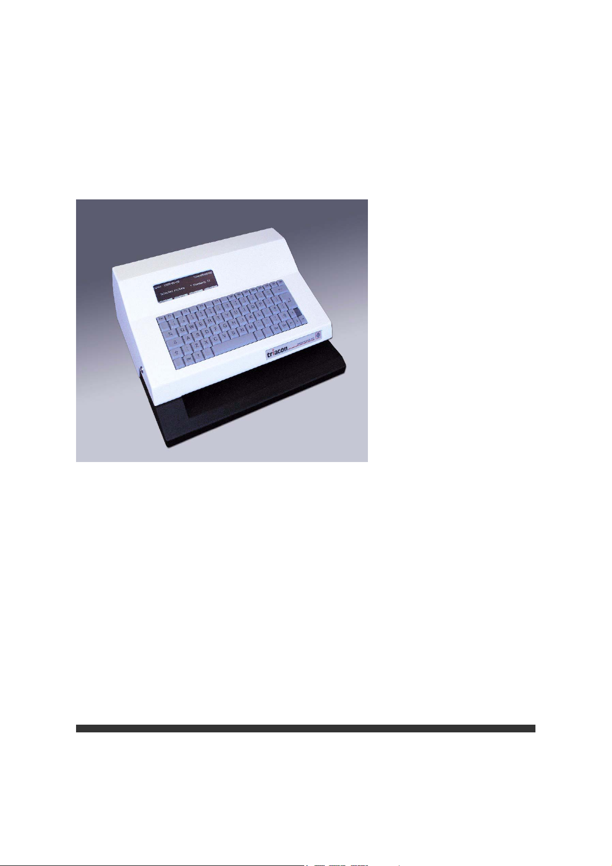
Network ID Camera
Installation Instructions
SP
NIC2-2
© Siemens AG 2003
The reproduction, transmission or
use of this document or its contents
is not permitted without express
written authority. Offenders will be
liable for damages. All rights,
including rights created by patent
grant or registration of a utility
model _or_ design,_are_ reserved.
English
Print No.: SP00-000.812.04.01.02 Doc. Gen. Date: 01.03
Replaces: n.a.
Network Installation Manual
Publication No. 201100
January 2003
NIC2-2
Network ID Camera

PLEASE NOTE
The information contained herein is based on the experience and knowledge rela-
ting to the subject matter gained by Triacon prior to publication.
No patent license is granted by this information.
Triacon reserves the right to change this information without notice, and makes no
warranty, expressed or implied, with respect to this information. Triacon shall not be
liable for any loss or damage, including consequential or special damages, resulting
from the use of this information, even if loss or damage is caused by Triacon's neg-
ligence or other fault.
© Triacon AB, Sweden 2003


NIC2-2 · Network ID Camera Publication no. 201100
Contents
1 Data Download1
1.1 Warning 1
1.2 Patient data 1
1.2.1 General .......................................................................................................1
1.2.2 Direct mode.................................................................................................1
1.2.3 Download mode ..........................................................................................1
1.2.4 Magnetic card reader .................................................................................. 2
1.2.5 Physical connection ....................................................................................2
1.3 X-ray data 2
1.3.1 General .......................................................................................................2
2 The Protocols 3
2.1 Patient data 3
2.1.1 General .......................................................................................................3
2.1.2 Network ID Camera Download protocol...................................................... 3
2.1.3 Direct protocol.............................................................................................4
2.1.4 Field List......................................................................................................4
2.1.5 Protocols compatible with the KODAK X-OMATIC Identification Camera,
Model 20105
2.1.6 Examples .................................................................................................... 6
2.2 X-ray data 8
2.2.1 General .......................................................................................................8
2.2.2 MMAT3000 ................................................................................................. 8
2.2.3 MMAT300 .................................................................................................10
2.2.4 PLANMED................................................................................................. 13
2.2.5 Senograph ................................................................................................15
2.2.6 SENO800T................................................................................................17
2.2.7 I-IMAGING ................................................................................................19
2.2.8 LORAD......................................................................................................21
2.2.9 GXDP-P/-NP .............................................................................................22
2.3 Others 27
2.3.1 General .....................................................................................................27
2.3.2 SLP100 .....................................................................................................27
2.3.3 C-FIXED....................................................................................................27
Triacon AB Sweden i Janury 2003

Publication no. 201100 NIC2-2 · Network ID Camera
3 Physical connection 29
3.1 The HOST connector 29
3.2 The AUX connectors 30
3.3 The NET Connector 30
3.4 Building a RS422 Network 32
3.4.1 Installing Procedure ..................................................................................33
3.4.2 Troubleshooting RS422 ............................................................................34
3.5 Built in diagnostic software 35
3.5.1 Serial analyser ..........................................................................................35
3.5.2 System logger ...........................................................................................36
Appendix A 39
ISO-8859-1 Character set 39
January 2003 ii Triacon AB Sweden

NIC2-2 · Network ID Camera Publication no. 201100
1. Data Download
1.1 Warning
The Network ID Camera is classified as a Medical Device and fulfills EN 60950.
According to European Safety Regulations for Medical Equipments, the following conditions
must be fulfilled:
- if the camera is operated within a distance of 1.5 m from the patient, it must be
connected to the equipotential equalization device (E
provided by the customer.
The purpose of the E
connected to the same ground potential.
- if the camera is connected to a Medical Equipment according toEN 60601-1
( e.g. safety ground or data connections) the safety standard EN 60601-1-1 has
to be met and documented.
2
D is to ensure that all medical and other equipments are
2
D). E2D with cable must be
1.2 Patient data
1.2.1 General
The Network ID camera is able to receive patient data from a patient booking system. This
can be achieved in two ways depending on how the booking system works.
The Network ID Camera can also receive patient data from a magnetic card through a card
reader connected to it.
1.2.2 Direct mode
This mode is used when each camera can be connected to its own terminal of the booking
system. When a patient arrives to the examination room and that is registered at the terminal
of the booking system the booking system immediately sends the patient data to the camera
which immediately displays it. This means that no user interaction is necessary on the camera to make the camera ready for marking.
1.2.3 Download mode
This mode is used when all cameras are connected to the central computer of the booking
system through one serial channel or if there are no terminals in each room. In download
mode a complete patient list is sent to each camera and operator has to bring up this list on
the camera to select the patient when the patient arrives at the examination room. In this
case all cameras are connected in parallel to one serial channel on the host computer.
Except for patient data, time and date of the booking is also sent which the Network ID Camera uses to sort the booking list. When the user brings up the booking list the patient nearest
in time is pointed out. This means that the user only needs a few keystrokes to select the
patient. To allow a camera to only store patients intended for a specific room each patient
data record is associated with a camera name and the camera may reject all patients not
intended for a specific room. Note that it is possible for more then one camera to have the
same name for example if there are many rooms that do the same examination and the patients are taken to the room that gets available first. Patients can be sent to the booking list
at any time and any number of times. Duplicates are thrown away and when the booking list
becomes full the patient with the oldest booking time is removed from the list.
Triacon AB Sweden 1 January 2003

Publication no. 201100 NIC2-2 · Network ID Camera
1.2.4 Magnetic card reader
A connented card reader is sending its data to the Network ID Camera in the same way as
the ”Direct protocol”. This means that the patient data is displayed on the camera immediatly
after the card has been swapped through the reader. Additional data can be added manually
if necessary.
1.2.5 Physical connection
There are two ways to physically connect the camera to a booking system. Any of the connections can be used with any of the protocols above. Just remember that if the direct protocol is used cameras can not be connected in parallel as they would in that case bring up
the same patient at the same time and that is not very functional.
One is through a RS232 interface. This is the normal way to use when using the direct mode
as one camera is connected to one host computer. Note that communication is one-directional, from the host to the camera, which means that it is possible to connect more then one
camera to one host using RS232 but as the driving capacity of RS232 is limited, which affects both maximum cable length and number of cameras, this is not recommend.
The other is through a RS422 interface. This is the normal way to use when using the download mode. It allows longer cables (up to hundreds of meters depending on which sender is
used) and it allows may cameras to be connected in parallel. It can of cause also be used
with the direct protocol for example if the cable distance is too long for RS232.
A card reader is connected through a SR232 interface.
1.3 X-ray data
1.3.1 General
The Network ID Camera is able to receive and exposure data, like kV and mAs, from a Xray unit. When the X-ray unit makes an exposure, exposure data is sent to the Network ID
Camera and when the film later is marked by Network ID Camera the exposure data is printed on the film together with patient data.
Network ID Camera can be connected as usual to a booking system for downloading patient
data. One camera is needed for each X-ray unit.
The sequence of operation is that when the patient arrives for the research patient data is
entered into the camera the usual way (manually or through booking system). After an exposure is made the exposure data is immediately sent from the X-ray unit to Network ID
Camera. The cassette should immediately after the exposure be brought to the camera and
marked. The camera only stores data from the latest exposure. If Network ID Camera would
store data from many exposures to allow many cassettes to be marked afterwards there is
a big risk of exchanging cassettes so there are many reason to force an immediate marking.
To prevent a cassette to be marked when there is no exposure data Network ID Camera can
be configured to not allow marking if exposure data is not available. When a marking is
made the exposure data is immediately erased to prevent two cassettes to be marked with
the same data by mistake.
January 2003 2 Triacon AB Sweden

NIC2-2 · Network ID Camera Publication no. 201100
2. The Protocols
2.1 Patient data
2.1.1 General
Four protocols are available. Two protocols were created for the Network ID Camera with
the intention of giving a flexible protocol which can handle language dependent information
and can transfer more data then just the name and patient ID. Two other protocols were implemented to be compatible with the KODAK X-OMATIC Identification Camera Model 2010
that was sold in the Nordic countries between 1990 and 1993. We do not recommend that
new software are written for these protocols.
The protocols in the camera are called;
DIRECT The Network ID Camera direct mode
protocol
DOWNL The Network ID Camera download
protocol
2010 B A protocol compatible with the
KODAK X-OMATIC Identification
Camera Model 2010 used when the
camera is connected to a transmitter
box called MNT10.
2010 D A protocol compatible with the
KODAK X-OMATIC Identification
Camera Model 2010 used when the
camera is connected without the
MNT10.
All protocols accept national characters according to ISO8859-1 standard, please refer to
appendix A.
2.1.2 Network ID Camera Download protocol
The protocol:
#group;date;time;fieldlist#CR,LF
Group is the name of the lab where the camera(s) are located. This may be used to
select which camera(s) should store which patients. If this field is left blank
(the trailing ; must be included) the camera will accept the patient data regardless of the name of the camera. This can be used as a broadcast to all
cameras.
Date is the booked date for the research. Date format is YYMMDD or DDMMYY
depending on which country the camera is configured for. The same format
is used as when displaying the date information in the main window of the
camera.
Time is the booked time for the research. Time format is HHMM. The date and time
information is used to sort the list and to be able to point out "best guess"
when opening the window with the list of patients.
Triacon AB Sweden 3 January 2003

Publication no. 201100 NIC2-2 · Network ID Camera
Field list This is described below as it is the same format as for direct communication.
At least one name field must be included in the field list and for countries using patient ID a patient ID field must also be included. See field list specification below for more details
CR,LF These two characters terminates the block. To make the protocol as compat-
ible as possible the camera will accept, CR only, LF only and any sequence
of CR and LF.
Trailing and leading spaces in all fields in the field list are removed so if the programming
language used for the sender software has problems sending variable length text strings (as
some COBOL dialects do), just pad with spaces and the camera will remove them. Just
make sure that the total length including leading and trailing '#' does not exceed 128 characters.
2.1.3 Direct protocol
This protocol is used when one camera is connected to one terminal. When the patient data
is sent from the computer the patient data window is immediately opened with the data
transferred.
#window;field list#CR,LF
Window is a single digit telling which cassette window should be used. Currently two
are defined. '1' is the standard C1 window, '2' is the narrow C1N window. If '*'
is used instead of a digit the window currently selected by the operator is
used.
Field list This is described below as it is the same format as for download
communication.
CR,LF These two characters terminates the block. To make the protocol as compat-
ible as possible the camera will accept, CR only, LF only and any sequence
of CR and LF.
The following string may be sent to the camera to close the window when the examination
has finished.
#QUIT#CR, LF
Trailing and leading spaces in the patient ID and name fields and fields in the field list are
removed so if your program has problems sending variable length text strings (as some COBOL dialects do), just pad with spaces and the camera will remove them. Just make sure
that the total length including leading and trailing '#' does not exceed 128 characters.
2.1.4 Field List
The field list contains the information that will be displayed in the different fields of the window.
The field is in the following format:
nr:text
nr is the two-digit field number, text is any text that fits into the field. If the field is too long
the camera will just truncate the text to make it fit. If more then one field should be transferred more fields can be transferred by separating them with ';'.
There are also three special fields used by the download protocol:
I:PID
N:name
January 2003 4 Triacon AB Sweden

NIC2-2 · Network ID Camera Publication no. 201100
Nn:name
PID is the patient ID of the patient. It should be in the format defined in the
country where the camera is used. If the patient ID is invalid it will be displayed as a spare patient ID (underlined) number when appearing on the
display. The patient ID field is mandatory for countries using patient ID
when using the download protocol.
Name is the name of the patient. This field is always mandatory when using the
download protocol.
In the Nn: field 'n' represents a number from 1 to 9. This is used if more then one name
field is defined in the window. When the patient name is displayed in the booking list of
the camera all Nn fields are merged together with a comma in between. The N1 field
will be displayed in the first name field of the window, N2 in the second and so on.
The field number here is not the field number presented in the left column of the exposure window set-up. Instead there is a translation table setting the correspondence between the field number in the message and the field number of the exposure window.
This is because we want the user be able to change the configuration of the camera
without having to change the program in the host computer.
From the programmers point of view, he or she can select numbers sequentially from 0
and upwards for his information and the person who configures the camera then sets
where that data will be displayed. This way the programmer must not know how the
camera is configured. If there is no information for a field it can be completely omitted.
It is legal to send information for field 1 and 3 for one patient and 1 and 2 for some other
patient. Just watch out so that the total length of the protocol is not longer then 128 characters.
As a feature to make it easier to send data from programs through a printer driver which
is page oriented CR/LF is allowed before any semicolon. This way it is possible to send
data from a MS-WINDOWS® program by defining a printer of type generic and design
a report with fields put on different lines and then send the data to the camera by printing
such a report.
2.1.5 Protocols compatible with the KODAK X-OMATIC Identification Camera, Model 2010
Because of compatibility reasons the protocol of the KODAK X-OMATIC Identification
Camera Model 2010 is also included in the Network ID Camera. KODAK X-OMATIC
Identification Camera, Model 2010 was sold in the Nordic countries between 1990 and
1993. We strongly recommend that no new software is written for any of these protocol.
Two versions of this protocol are available.
2010 B A protocol compatible with the KODAK X-OMATIC Identifica-
tion Camera Model 2010 used when the camera is connected
to a transmitter box called MNT10.
This protocol includes the STX, "2" and ETX characters of the
description below.
2010 D A protocol compatible with the KODAK X-OMATIC Identifica-
tion Camera Model 2010 used when the camera is connected
without MNT10.
This protocol excludes the STX, "2" and ETX characters of the
description below.
Triacon AB Sweden 5 January 2003

Publication no. 201100 NIC2-2 · Network ID Camera
If a field contains more characters then needed, the field should be padded with
spaces.
National characters like ÅÄÖ can be sent either as 7-bit ANSI code or as 8 bit ISO 88591 or the code page 850 code which DOS uses. Please refer to appendix A.
2010 B 2010 D
0 STX 0x02 Start of text
1 '2' 0x32 Source, always '2'
2 .. 7 0 .. 5 Address
8 6 ' ' 0x20 Separator
9, 10 7, 8 DD Booked date, Day, (for Sweden year)
11, 12 9, 10 MM Booked date, Month
13,14 11, 12 YY Booked date, Year, (for Sweden day)
15 13 ' ' 0x20 Separator
16, 17 14, 15 HH Booked date, Hour
18, 19 16, 17 MM Booked date, Minute
20 18 ' ' 0x20 Separator
21 .. 60 19 .. 58 Name, 40 characters
61 59 ' ' 0x20 Separator
62 .. 72 60 .. 70 Patient ID (11 to 14 char, no check)
73 71 CR 0x0d Carriage return
74 72 LF 0x0a Linefeed
75 ETX 0x03 End of text
2.1.6 Examples
Below follow some examples of all of the protocols.
Example download protocol
Let's say that you like to send the patient ID "950822-1234" the patient name "Eric Johnsson" and one line of text "Broken leg" to the camera and any window should be used. The
following string should be sent to the camera.
#LAB1;960824;1200;I:950822-1234;N:Erik Johnsson;1:Broken leg#CR,LF
In next example a patient ID and data for two name fields are sent and also text for two
other fields.
#LAB1:960824;1215;I:950822-1234;N1:Eric;N2:Johnsson;1:150 ml contrast;2:Car-
dio#CR,LF
Example direct protocol
Let's say that you like to send the patient ID "950822-1234" the patient "Eric Johnson"
and one line of free text "Broken leg" to the camera and any window should be used. The
following string should be sent to the camera.
#*;01:950822-1234;02:Eric Johnson;03:Broken leg#CR,LF
January 2003 6 Triacon AB Sweden

NIC2-2 · Network ID Camera Publication no. 201100
Example of protocol compatible with the KODAK X-OMATIC IDENTIFICATION CAMERA, MODEL 2010
In the 2010 camera the field lengths, and hence the record length, are fixed and to show
this the period character is used to show the space character below:
STX
2
LAB1...960824.1215
Eric Johnson............................
950822-1234
CR
LF
ETX
2.2
Triacon AB Sweden 7 January 2003

Publication no. 201100 NIC2-2 · Network ID Camera
2.2 X-ray data
2.2.1 General
Network ID Camera has eight built in software selectable communication protocol for receiving X-ray data.
MMAT3000 Receiving data from Siemens Mammomat® 3000.
MMAT300 Receiving data from Siemens Mammomat® 300.
PLANMED Receiving data from PLANMED Models Classic and Sophie.
SENOGRAPH Receiving data from GE Medical System Senographe Models DMR, DMRV2
and Senix.
SENO800T Receiving data from GE Medical System Senographe 800T.
I-IMAGING Receiving data from INSTRUMENTARIUM Models Alfa, Diamond and Per-
forma.
LORAD Receiving data from LORAD Model IV.
GXDP Is a General X-ray Data Protocol.
2.2.2 MMAT3000
14 different exposure data are sent from the Mammomat® and each and one of them can
be individually placed on the picture, more about that below. The following data's are available.
Data Value Length
Focus SF/LF* 2
Anode W/Mo* 2
Filter Rh/Mo* 2
kV 0 to 99kV 2
mAs 0 to 999 mAs 3
Exp.time 0 to 99999 ms 5
Magnification 0.00 to 9.99 4
Force 0 to 99 Kg 2
Thickness 0 to 999 mm 3
Grid No grid/Grid* 7
Density -9.9 to +9.9 4
Angle -180 to +180 degree 4
Dose 0.0 -99.9, 100 - 999 mGy 4
Option Not used 6
* The texts displayed here may be changed in Network ID Camera. The data is sent as 0
or 1 from the Mammomat® and translated by Network ID Camera to the appropriate texts.
January 2003 8 Triacon AB Sweden

NIC2-2 · Network ID Camera Publication no. 201100
Configuration of Network ID Camera
Configuration of Network ID Camera for connection with the Mammomat® can be divided
into two parts. One is to configure the serial channel for communication with the Mammomat®, the other is to create the picture that will be printed on the film.
The Mammomat® is connected to the AUX1 connector at the back of the Network ID Camera. The communication is set-up by entering set-up mode of the camera, please refer to
the Installation and Setup Manual. When in the communication set-up, press the F1 key so
that the word "Channel: AUX1" is displayed in the upper right corner. The set-up should now
be set to:
Baudrate 9600
Parity NONE
Databits 8
Protocol MMAT3000
As mentioned above when the different data available is shown the texts for a few items can
be changed (those marked with *). This is done by opening a new set-up window by pressing
Shift-F1 from this set-up window.
Creating the picture which will be printed on the film is done in the same way as usual except
that there is one extra field type available. The COMM field type. When such a field is selected and enter is pressed an extra selection appears in the window called COMM: were
you select which kind of exposure data should be displayed in the field. To build a picture
you will have to define one COMM field for each exposure data to display. Note that the field
data do not include the unit (kV mAs and so on). To add that an F-text field with the appropriate text has to be inserted after the COMM field.
The Mammomat®
The exposure data connection works with Mammomat® 3000 equipped with software version 1.6 or later. Also the hardware must be up to date. Serial numbers starting at 2486 and
later are up to date. Siemens Elema estimates that equipment fulfilling these requirements
are delivered from spring 1996. Earlier versions of the Mammomat® 3000 may be updated
both regarding hardware and software.
In addition to the requirements above the Mammomat® must also be equipped with a printer
interface. The installation kit for the printer interface includes a printer cable and below follows a description on how to make an adapter between this cable and Network ID Camera.
Since the printer cable is standard with the printer interface we recommend using this cable
and adding an adapter rather than making a completely new cable.
If the correct Mammomat® software and hardware are installed the Mammomat® will automatically configure it self for use with the Network ID Camera when the Network ID Camera
is connected.
The Network ID Camera
If the Mammomat® is ready you will only need a standard equipped Network ID Camera and
a cable between the Mammomat® and Network ID Camera to get it to work.
Triacon AB Sweden 9 January 2003
 Loading...