


Network ID Camera
Installation and Startup
SP
NIC2-1
© Siemens AG 2001
The reproduction, transmission or
use of this document or its contents
is not permitted without express
written authority. Offenders will be
liable for damages. All rights,
including rights created by patent
grant or registration of a utility
model _or_ design,_are_ reserved.
English
Print No.: SP00-000.814.02.01.02 Doc. Gen. Date: 03.01
Replaces: n.a.
Installation and Setup Manual March 2001
Publication No 201001
NIC2-1
Network ID Camera


PLEASE NOTE
The information contained herein is based on the experience and knowledge relating to the
subject matter gained by Triacon prior to publication.
No patent license is granted by this information.
Triacon reserves the right to change this information without notice, and makes no warranty,
expressed or implied, with respect to this information. Triacon shall not be liable for any loss
or damage, including consequential or special damages, resulting from the use of this
information, even if loss or damage is caused by Triacon’s negligence or other fault.
© Triacon AB, Sweden, 2001


Table of Contents
Description Page
1 General .................................................................................................................... 3
2 Installation .............................................................................................................. 3
2.1 Unpacking ................................................................................................................................. 3
2.2 Installation Details.................................................................................................................... 3
3 Setup ....................................................................................................................... 5
3.1 Getting into setup mode. ......................................................................................................... 5
3.2 Resetting to factory default...................................................................................................... 5
3.3 Main configuration window ..................................................................................................... 5
3.4 Pictures and settings ............................................................................................................... 6
3.4.1 Some frequently used words ..............................................................................................7
3.4.2 Picture Standard, C1/Min-R2, C1N..................................................................................... 7
3.4.2.1 Editing a field 8
3.4.3 Settings Standard, C1/Min-R2, C1N................................................................................. 10
3.4.4 Menus.............................................................................................................................. 11
3.5 Bookinglist configuration ...................................................................................................... 12
3.5.1 Settings............................................................................................................................ 12
3.5.2 Define input fields ............................................................................................................ 13
3.5.3 Link field to patient window............................................................................................... 13
3.6 Communication param ........................................................................................................... 14
3.6.1 Communication parameters Channel: HOST .................................................................... 14
3.6.1.1 Protocol set-up 15
3.6.2 Communication parameters Channel: AUX ...................................................................... 16
3.6.2.1 Protocol set-up SIEMENS Mammomat® 3000 16
3.6.2.2 Protocol set-up GE Medical System Senographe 18
3.6.2.3 Protocol set-up GXDP 19
3.6.2.4 Protocol set-up SIEMENS Mammomat® 300 20
3.6.2.5 Protocol set-up PLANMED 20
3.7 Settings ................................................................................................................................... 21
3.8 Remote control ....................................................................................................................... 22
3.8.1 Save a Set-up.................................................................................................................. 23
3.8.2 Load a Set-up................................................................................................................... 23
4 Upgrading the firmware ....................................................................................... 25
4.1 Download the firmware .......................................................................................................... 25
Triacon AB Sweden March 2001
i

5 Error Messages..................................................................................................... 27
5.1 Illegal value..............................................................................................................................27
5.2 The adjustment may be max 32 ..............................................................................................27
5.3 Out of storage for FTEXT........................................................................................................27
5.4 Length must be between 1 and 8............................................................................................27
5.5 Communication error ..............................................................................................................27
5.6 Programming voltage missing (JP8) ......................................................................................27
5.7 Failed to erase set-up memory ...............................................................................................28
5.8 Failed to program set-up memory ..........................................................................................28
5.9 Unknown programming error .................................................................................................28
March 2001 Triacon AB Sweden
ii

Publication No. 201001 NIC2-1 • Installation and Set-up Manual
1 General
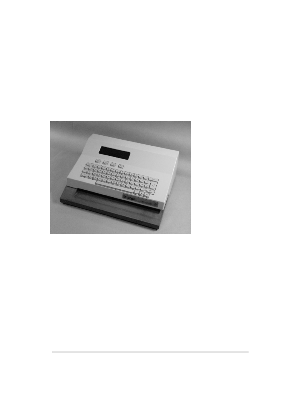
This manual describes how to install and setup the Network ID Camera herein called
NIC. This includes anything from installation to setting-up what the picture printed on
the film should look like, which language for the display, to how it should communicate
with a booking system.
This manual is written for software version 2.2 and it is assumed that language is set
to English. Note that you may select language to English which causes all texts to be
displayed in English, but still select country to the country you are in to get countrydependent information, like date format and PID number, correct.
2 Installation
2.1 Unpacking
Check that the cardboard box is undamaged and has no holes or deep scratches. Any
damage must be reported to the transport company or the supplier whenever it can be
suspected that the camera has been damaged during transport.
The box contains the camera, an operator’s manual in local language and the power
cord. The keyboard should be equipped with the country dependent keycaps.
2.2 Installation Details
After unpacking the camera it should be placed on a steady table or shelf. If the
camera is operated in mobile units like mammography screening buses, or where
there is a risk of the camera falling down, it should be fastened to the surface with two
screws mounted from the inside of the camera through two holes in the bottom plate
with suitable screws.
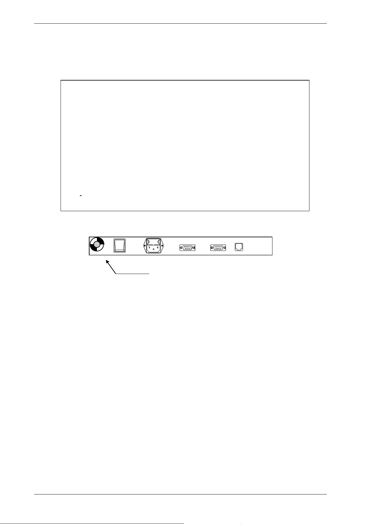
The power cord should be connected to the power receptacle on the backside of the
camera and to wall outlet.
No voltage selection is necessary, the camera can be operated at any voltage
from 95 VAC to 250 VAC 50/60Hz.
1
0
Power receptacle
Triacon AB Sweden March 2001
3
NIC2-1 • Installation and Set-up Manual Publication No. 201001
Check with customer that the keyboard has the local used keycaps.
Country keycap sets can be ordered as spare parts if needed.
Warning
The Network ID Camera is classified as a Medical Device and fulfils EN
60950.
According to European Safety Regulations for Medical Equipments, the
following conditions must be fulfiled:
- if the camera is operated within a distance of 1.5 m from the patient, it must
be connected to the equipotential equalization device (E2D).
E2D with cable must be provided by the customer.
The purpose of the E2D is to ensure that all medical and other equipments
are connected to the same ground potential.
- if the camera is connected to a Medical Equipment according to
EN 60601-1( e.g. safety ground or data connections) the safety standard
EN 60601-1-1 has to be met and documented.
1
0
E2D plug - Connector for the cable coming
from the equipotential bushbar.
March 2001 Triacon AB Sweden
4

Publication No. 201001 NIC2-1 • Installation and Set-up Manual
3 Setup
This section describes how the set-up of the camera is done. It assumes that the
operator is familiar with the camera.
3.1 Getting into setup mode.
Make sure the camera displays the main window which is the window that comes up
after the initial screen with the Triacon logo. The window shows:
Date: 031199 Time:15:45:48
Selected cassette : Standard, C1
Manual Booking Memory Cass type
To get into setup mode, press Shift F4 (the right soft-key while holding any of the two
shift keys down). A new window will appear asking for a password.
The Network ID Camera will remember the password for about 15 minutes and will not
ask you for the password again, if you exit and then enter set-up mode again within
15 minutes. This is to eliminate the need to re-type the password every time you leave
setup mode to test a configuration.
3.2 Resetting to factory default
Get into configuration mode as described in chapter 3.1. Then press Ctrl-E. This will
reset the memory of the Network ID Camera and restart the camera just as if you
were switching the power on again. Go to chapter ”Settings” to find out how to change
the language of your preference.
3.3 Main configuration window
Get into configuration mode as described in chapter 3.1.
Setup Ver: 2.2
Picture settings
Bookinglist configuration
Communication param
Settings
Sensor adjustment
Lock Up Down Exit
This is a menu from where to select what has to be set-up. Some of the selections will
present you yet another selection menu (first selection for example) while other
selections will present a window
where configurations can be changed (settings for example).
Triacon AB Sweden March 2001
5

NIC2-1 • Installation and Set-up Manual Publication No. 201001
The soft-keys are used as follows:
Lock Lock the set-up with a password. Will make the Network ID Camera ask
for password the next time set-up is entered. An alternative to LOCK is to
wait for the password time-out.
Up An alternative to using the up-arrow. Will move to the selection above the
current.
Down An alternative to using the down-arrow. Will move to the selection below
the current.
Exit Exit set-up mode.
Picture and settings
Here you can set details of how and what will be printed on the film.
Bookinglist configuration
Here all settings for manual entry of data to bookinglist is configured.
Communication param
Here all settings regarding the communication between the Network ID
Camera and the equipment connected to any of the four communication
ports can be changed.
Settings Here all settings of a more general nature can be changed, e.g. which
language the Network ID Camera speaks.
Sensor adjustment
This selection will show a picture showing the status of the three cassette
sensors. For detailed information, please refer to the Service manual.
Test functions
Here parameters regarding the opening of the cassette window can be
set. For detailed information, please refer to the Service Manual.
NOTE: This should only be done by trained service personnel.
Serial analyzer
Here all data, received on HOST or NET serial communication port, is
listed. For detailed information, please refer to the Network Installation
Manual.
Remote control
Here the down-/upload of a set-up is performed.
System logger
Here is listed errors and abnormal situations. For detailed information,
please refer to the Service Manual.
3.4 Pictures and settings
Choosing this selection will present five new alternatives.
Picture settings
Picture Standard, C1
Settings Standard, C1
Picture Min-R2, C1N
Settings Min-R2, C1N
Menus
Previous Next Exit
March 2001 Triacon AB Sweden
6
 Loading...