

Siemens NET-7 Installation Instructions Manual

Installation Instructions
Model NET-7
Communication Interface
INTRODUCTION
The Model NET-7 from Siemens Industry, Inc.,
provides a Style 7 communication interface between
the main MXL and multiple remote panels in an MXL
system using two separately supervised RS-485
pairs. Each NET-7, except the NET-7 connected to
the MMB, electrically isolates the pairs from the local
power supply and isolates ground faults to a single
remote panel. The MMB provides ground fault
detection for the two pairs.
Each NET-7 connected represents one network drop
on the MXL System. There can be a maximum of 32
drops. The NET-7 has a network address which must
be set on the module and installed into the CSG-M
network map.
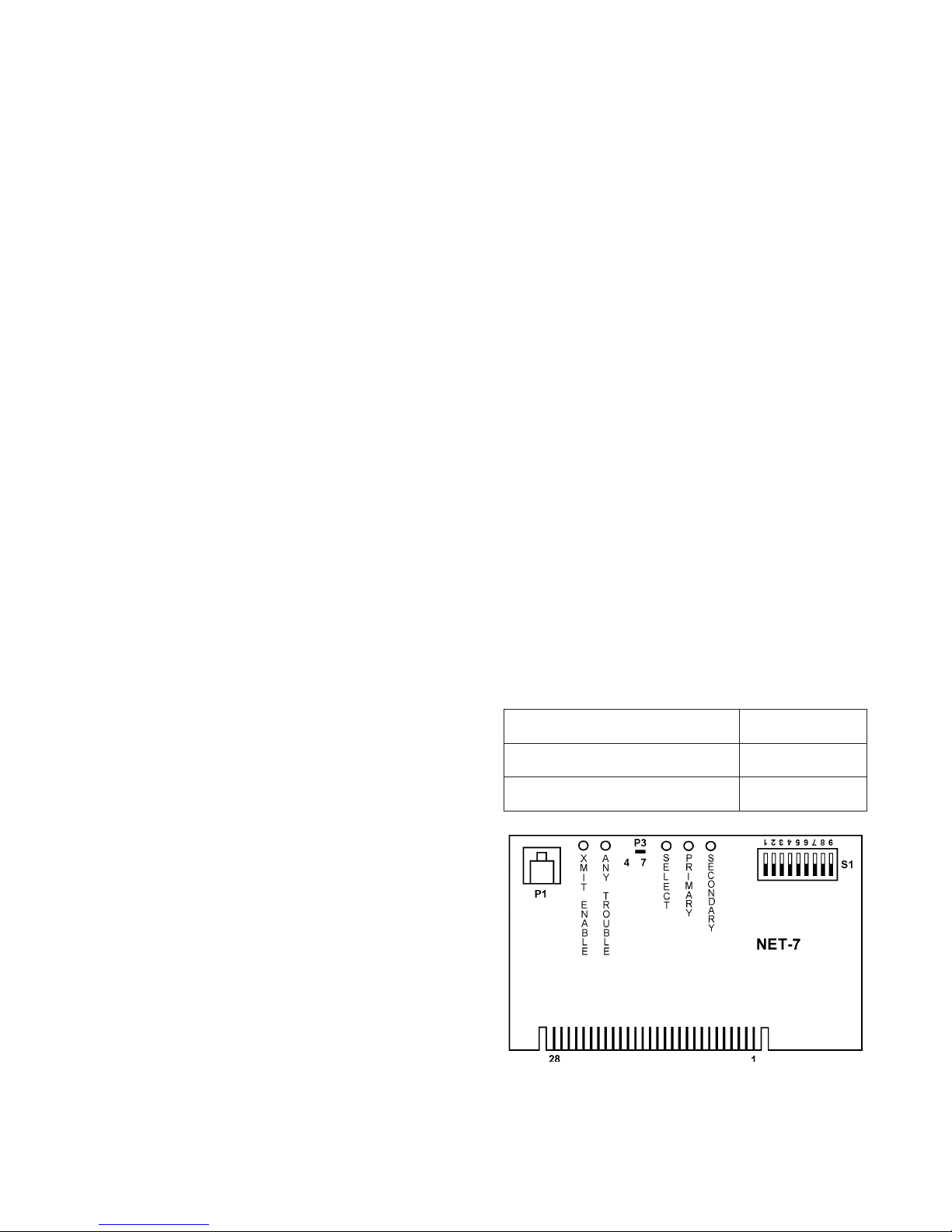
The NET-7 has two yellow LEDs:
1. XMIT ENABLE lights whenever the NET-7
transmits a message.
2. ANY TROUBLE lights when the NET-7 is unable
to communicate to the MMB on either pair.
Three green LEDs on the NET-7 indicate the state
of two communication pairs. The first two LEDs,
PRIMARY and SECONDARY, light whenever the
NET-7 receives a message on that pair. Use these
two LEDs when troubleshooting to determine if a
pair is active. The third green LED, SELECT,
indicates the communication pair currently connected
to the modules in the enclosure. In normal operation,
the SELECT LED turns on and off every time there is
network activity. If this LED remains in one state
(either on or off), it indicates that one or both of the
pairs is not functional. The SELECT LED lights when
the PRIMARY pair is selected.
The NET-7 can also provide a Style 4 communication
mode. In that configuration all NET-7s must be set to
Style 4. Use P3 on the NET-7 to make this selection.
CAUTION: NET-7s and NET-4s cannot be
combined in the same system.
The NET-7 offers advanced performance over the
NET-4. Each NET-7 determines which modules are
installed in its enclosure and reports this information
to the MMB where it is compared to the CSG-M data
base. That information verifies that the system is
properly installed. The default setting in the MXL has
this feature deactivated. The user can change the
default setting in CSG-M or temporarily change the
setting by selecting the OVERRIDE submenu of the
TEST menu in the MXL. When using the MXL menu,
the change remains in effect until power is removed.
Error checking is available in either Style 4 or Style 7.
All terminals are power limited.
For additional information on the MXL/MXLV System,
refer to the MXL/MXLV Manual, P/N 315-092036.
Siemens Industry, Inc.
Building Technologies Division
Florham Park, NJ
P/N 315-091914-13
Siemens Building Technologies, Ltd.
Fire Safety & Security Products
2 Kenview Boulevard
Brampton, Ontario
L6T 5E4 Canada
INSTALLATION
Remove all system power before installation,
first battery and then AC. (To power up, first
connect the AC and then the battery.)
All wiring must comply with national and
local codes.
• If screws are in the location where the card
guide is to be installed, remove the screws
and mount the card guide with the hardware
supplied.
• Mount the two card guides supplied onto the
PSR-1 by loosening the screws above and
below P7. Then slide the guides under the
screws and tighten them.
1. Remove the NET-7 from the antistatic bag.
CAUTION: Do not touch the gold plated
card edge on the NET-7.
2. Set the address for the NET-7 using switch S1.
Refer to Table 1 for the switch settings. Be sure
that the address agrees with the CSG-M network
map.
3. Determine whether the communication mode is
Style 4 or Style 7. Place the shorting jumper on
P3 to agree with the style selected. (See Figure 1
for the location of P3.)
NOTE: On the MMB set jumper P15 to the S7
position regardless of the communication
mode (Style 4 or Style 7) selected on the
NET-7.
4. Decide whether to install the NET-7 into a PSR-1
or into the enclosure with the MMB. If the
installation is in a PSR-1, skip to step 8.
5. Install the NET-7 that is in the enclosure with the
MMB in a MOM-4 slot. Any available MOM-4 slot
can be used. Mount one of the two card guides
provided in the MOM-4. Slip the guide under the
mounting screw in the center of the MOM-4 and
tighten.
9. Refer to Figure 2 for the wiring diagram. Connect
the network wires to TB4 on the PSR-1 as shown.
10. Install the NET-7 into P7. Be sure that the board
is firmly seated.
11. If an MKB-2 is installed, the NET-7 must be
located in a MOM slot. In this configuration, the
setting in the CSG-M for the PSR-1 style type
should be none and a NET-7 should be installed
in the network map.
Note on End of Line Resistors
End of line resistors are provided with each NET-7.
DO NOT PLACE AN END OF LINE RESISTOR AT
EACH NET-7. These devices are required at the two
extreme ends of each network pair as shown in
Figure 2. It is not required that the MMB be at one of
the ends. It may be at any location along the network. T-Tapping is not allowed on the network.
ELECTRICAL RATINGS
tnerruCeludoMCDV5evitcAAm021
tnerruCeludoMCDV42evitcAAm0
tnerruCeludoMCDV42ybdnatSAm03
6. Refer to Figure 2 for the wiring diagram. Check
all wiring prior to installing the NET-7 into the
MOM-4. Failure to properly wire the NET-7 can
cause damage to the board.
7. Install the NET-7 into the MOM-4 slot. Be sure
that the board is firmly seated in the card edge
connector. This completes the installation of the
NET-7 with the MMB.
8. When used with a PSR-1, install the NET-7 into
connector P7.
Figure 1 NET-7 Board
2
 Loading...