

Page 1

Preface, Contents
SIMATIC NET
NCM for Industrial Ethernet
Manual
for NCM S7 V5.2 and higher
Communication via Ethernet CPs
in S7 Stations
Installing and Starting the
Ethernet CP with STEP 7
SEND/RECEIVE
interface
Configuring Communication
Connections
Programmed Communication
Connections
Programming FCs (Functions)
and FBs for S7 Ethernet CPs
NCM S7 Diagnostics
Firmware loader
1
2
3
4
5
6
7
8
Release 6/2003
C79000–G8976–C129–07
Appendix
References
Glossary
Linking to Other Systems with
FETCH/WRITE
Document History
Index
A
B
C
D
Page 2

Classification of Safety-Related Notices
This manual contains notices which you should observe to ensure your own personal safety, as well as to protect the product and connected equipment. These notices are highlighted in the manual by a warning triangle and are marked as follows
according to the level of danger:
Danger
!
!
!
indicates that death or severe personal injury will result if proper precautions are
not taken.
Warning
indicates that death or severe personal injury can result if proper precautions are
not taken.
Caution
with warning triangle indicates that minor personal injury can result if proper precautions are not taken.
Caution
without warning triangle indicates that damage to property can result if proper precautions are not taken.
Notice
indicates that an undesirable result or status can occur if the relevant notice is
ignored.
Note
highlights important information on the product, using the product, or part of the
documentation that is of particular importance and that will be of benefit to the
user.
2
SIMATIC NET NCM S7 for Industrial Ethernet
C79000–G8976–C129–07
Release 6/2003
Page 3

Trademarks
SIMATICR, SIMATIC HMIR and SIMATIC NETR are registered trademarks of
SIEMENS AG.
Third parties using for their own purposes any other names in this document which
refer to trademarks might infringe upon the rights of the trademark owners.
Safety Instructions Regarding your Product:
Before you use the product described here, read the safety instructions below
thoroughly.
Qualified Personnel
Only qualified personnel should be allowed to install and work on this equipment.
Qualified persons are defined as persons who are authorized to commission, to
ground, and to tag circuits, equipment, and systems in accordance with
established safety practices and standards.
Correct Usage of Hardware Products
Note the following
Warning
!
This device and its components may only be used for the applications described in
the catalog or the technical description, and only in connection with devices or
components from other manufacturers which have been approved or recommended by Siemens.
This product can only function correctly and safely if it is transported, stored, set
up, and installed correctly, and operated and maintained as recommended.
Before you use the supplied sample programs or programs you have written yourself, make certain that no injury to persons nor damage to equipment can result in
your plant or process.
EU Directive: Do not start up until you have established that the machine on which
you intend to run this component complies with the directive 89/392/EEC.
Correct Usage of Software Products
Note the following
Warning
!
This software may only be used for the applications described in the catalog or the
technical description, and only in connection with software products, devices, or
components from other manufacturers which have been approved or recommended by Siemens.
Before you use the supplied sample programs or programs you have written yourself, make certain that no injury to persons nor damage to equipment can result in
your plant or process.
SIMATIC NET NCM S7 for Industrial Ethernet
Release 6/2003
C79000–G8976–C129–07
3
Page 4

Prior to Startup
Before putting the product into operation, note the following warning:
Caution
Prior to startup you must observe the instructions in the relevant documentation.
For ordering data of the documentation please refer to the catalogs or contact your
local SIEMENS representative.
Disclaimer of LiabilityCopyright E Siemens AG 2001–2003 All rights reserved
The reproduction, transmission or use of this document or its contents is not
permitted without express written authority. Offenders will be liable for
damages. All rights, including rights created by patent grant or registration of
a utility model or design, are reserved.
Siemens AG
Automation and Drives
Industrial Communication
Postfach 4848, D-90327 Nürnberg
4
Siemens Aktiengesellschaft G79000-G8976-C129-07
We have checked the contents of this manual for agreement with the hardware and software described. Since deviations cannot be precluded entirely, w e
cannot guarantee full agreement. However, the data in this manual are reviewed regularly and any necessary corrections included in subsequent editions. Suggestions for improvement are welcomed.
Subject to technical change.
SIMATIC NET NCM S7 for Industrial Ethernet
Release 6/2003
C79000–G8976–C129–07
Page 5
This Manual on SIMATIC NET NCM S7 for Industrial Ethernet
...supports you when using the communication services provided by the SIMATIC
NET communications processors (Industrial Ethernet CPs) for communication on
SIMATIC NET with Industrial Ethernet in the management and cell areas.
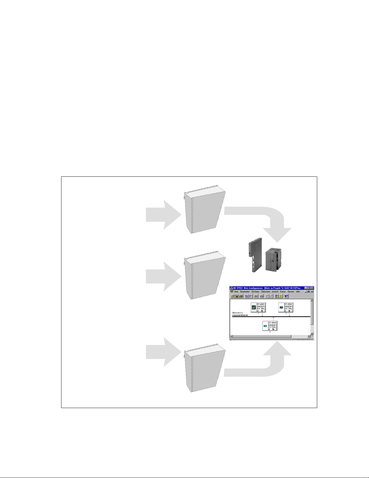
The documentation on your S7 CPs and NCM S7 is in several parts that fit
together as shown below:
S S7-CP
– selecting
– installing
– commissioning
– performance data
S S7-CP and STEP 7 / NCM S7
– familiarization
– testing interfaces
– commissioning
Manual
Primer
S7-CP
for
S7-300 /
S7-400
STEP 7
NCM S7
S Communication services
with STEP 7 / NCM S7
– programming
– configuring
– downloading /
commissioning
– diagnostics
SIMATIC NET NCM S7 for Industrial Ethernet
Release 6/2003
C79000–G8976–C129–07
NCM S7
Manual
5
Page 6

This Manual on SIMATIC NET NCM S7 for Industrial Ethernet
Audience
This manual is intended for personnel responsible for installing and programming
STEP 7 programs and for service personnel.
Scope of this Manual
This manual applies to version 5.2 and higher of the NCM S7 configuration
software for Industrial Ethernet and to version 5.2 and higher of the STEP 7
software.
This manual also includes specially marked passages that apply specifically to and
require version 5.2 SP1 of the NCM S7 for Industrial Ethernet configuration
software and version 5.2 SP1 of the STEP 7 software.
These include new functions for IP configuration:
S IP access protection
Using IP access protection gives you the opportunity of restricting access to the
local S7 station to partners with specific IP addresses.
S Configuring connections from the user program
In some situations, it is an advantage to set up communication connections not
over the configuration interface of STEP 7 but program-controlled by specific
applications.
As of STEP 7 V5.2 SP1, a function block is available for these applications that
allows flexible transfer of data blocks with configuration data to an Ethernet CP.
The description of the configuration for FETCH / WRITE services has been
extended.
Notice
Please note that the availability of new functions depends on the type of CP you
are using. You can check which functions your module supports in the description
in the Properties dialog in STEP 7 and in the catalog in HW Config.
The manual contains more detailed information /1/.
6
SIMATIC NET NCM S7 for Industrial Ethernet
C79000–G8976–C129–07
Release 6/2003
Page 7

Symbols Used in this Manual
Unless indicated otherwise, the functions described in this manual assume the use
of STEP 7. This symbol is used to indicate functions that require a specific version
of STEP 7 or higher, for example Version V5.2.
This symbol appears in the margin to draw your attention to useful tips.
This symbol indicates recommended documentation.
Where you see this symbol, you should also refer to additional information in the
basic help system of STEP 7.
This Manual on SIMATIC NET NCM S7 for Industrial Ethernet
F1
Conventions
This symbol indicates where detailed context-sensitive help is available. You can
display these help texts with the F1 key or by clicking on the “Help” button in the
relevant dialog.
References to other manuals and documentation are indicated by numbers in
slashes /.../. These numbers refer to the titles of manuals listed in the References
section of the Appendix.
SIMATIC NET NCM S7 for Industrial Ethernet
Release 6/2003
C79000–G8976–C129–07
7
Page 8

This Manual on SIMATIC NET NCM S7 for Industrial Ethernet
You will find additional information in the following sources:
This manual is also part of the NCM S7 for Industrial Ethernet documentation
package. These documents are also on the Manual Collection CD supplied with
every S7 CP and they are also available on the Internet. The following table
provides you with an overview.
Title Content
S7-CPs for Industrial
Ethernet
Manual
This is available on the Internet at:
The manual S7 CPs for Industrial Ethernet contains information on the
characteristics of the CPs and instructions on installation and connections.
S General Section: http://www4.ad.siemens.de/view/cs/de/8777865
S CP 343-1: http://www4.ad.siemens.de/view/cs/de/8777308
S CP 343-1 PN: http://www4.ad.siemens.de/view/cs/de/8776538
S CP 343-1 IT: http://www4.ad.siemens.de/view/cs/de/8776544
S CP 443-1: http://www4.ad.siemens.de/view/cs/de/8776219
S CP 443-1 IT: http://www4.ad.siemens.de/view/cs/de/8776322
NCM S7 for Industrial
Ethernet
Primer
Based on simple examples, the primer introduces you to the methods of
connecting and networking SIMATIC S7 stations with CPs on Industrial
Ethernet. It shows you how the communications calls are entered in the user
program to allow you to use the services via the SEND/RECEIVE interface.
Y ou will learn how simple it is to create a configuration for standard
applications using STEP 7 and the NCM S7 optional package.
The examples described here can also be found in the project folder for
sample programs after you have installed STEP 7 and the NCM S7 for
Industrial Ethernet option!
NCM S7 for Industrial
Ethernet
Manual
IT-CP
Manual
Advanced PC
Configuration
Commissioning PC
Stations
Manual
8
This is available on the Internet at:
http://www4.ad.siemens.de/view/cs/de/1172503
The manual is intended as a guide and reference work for configuring and
programming an Industrial Ethernet CP.
This is available on the Internet at:
http://www4.ad.siemens.de/view/cs/de/1172423
The manual is intended as a guide and source of reference when working with
the IT-CP. In addition to the functions provided by an Ethernet CP, the IT-CP
also provides functions for Internet technology.
This is available on the Internet at:
http://www4.ad.siemens.de/view/cs/de/1172744
Advanced PC Configuration is the new tool with which you can commission a
PC station as part of an industrial communication network.
The manual supports you and helps you to make efficient use of
communications with your PC applications in conjunction with the SIMATIC
NET modules. It explains the steps involved in configuration with NCM S7.
This is available on the Internet at:
http://www4.ad.siemens.de/view/cs/13542666
SIMATIC NET NCM S7 for Industrial Ethernet
C79000–G8976–C129–07
Release 6/2003
Page 9

This Manual on SIMATIC NET NCM S7 for Industrial Ethernet
Quick Start CD: Samples covering all aspects of communication
The Quick Start CD that can be ordered separately is a
treasure-trove of sample programs and configurations.
You can order this directly over the Internet at:
http://www4.ad.siemens.de/view/cs/de/574211
Additional Information on SIMATIC S7 and STEP 7
The following documentation contains additional information about the STEP 7
standard software of the SIMATIC programmable controllers and can be obtained
from your local Siemens office.
Topic Document
Basic information for technical
personnel using the STEP 7
standard software for control
tasks with S7-300/400
programmable controllers.
STEP 7 basics with
S Configuring hardware with STEP 7
S Programming with STEP 7
S Manual for converting from S5 to S7
S Primer for a fast start
The reference works describing
the programming languages
LAD/FBD and STL as well as the
standard and system functions in
addition to the STEP 7 basic
knowledge.
STEP 7 reference manuals with
S Manuals for LAD/FBD/STL
S Standard and system functions for S7-300/400
You will also find information on SIMATIC programmable controllers on the Quick
Start CD and from the Customer Support Online services at:
http://www.siemens.de/simatic-net General information
or
http://www.ad.siemens.de/csi/net Product information and downloads
SIMATIC NET NCM S7 for Industrial Ethernet
Release 6/2003
C79000–G8976–C129–07
9
Page 10

This Manual on SIMATIC NET NCM S7 for Industrial Ethernet
Access to Online Help of STEP 7 and NCM S7
With the online help, you can obtain the following information:
S You can display the contents of the STEP 7 basic help system with the menu
command Help –> Contents.
S Context-sensitive help on the selected object using the Help –> Context-Sensitive
F1
Help menu command, the F1 function key or the question mark in the toolbar.
You can then access further information relating to the current topic.
S Glossary for all STEP 7 applications by clicking the “Glossary” button.
Please note that each STEP 7 application has its own contents and
context-sensitive help.
-
10
SIMATIC NET NCM S7 for Industrial Ethernet
C79000–G8976–C129–07
Release 6/2003
Page 11

Contents
1 Communication via Ethernet CPs in S7 Stations 15. . . . . . . . . . . . . . . . . . . . . . . . . .
1.1 Industrial Ethernet 16. . . . . . . . . . . . . . . . . . . . . . . . . . . . . . . . . . . . . . . . . . . . . . .
1.2 SIMATIC S7 Communication with S7 Ethernet CPs 17. . . . . . . . . . . . . . . . . .
1.3 PG/OP Communication via Industrial Ethernet 21. . . . . . . . . . . . . . . . . . . . . .
1.3.1 PG Communication with STEP 7 over Industrial Ethernet 23. . . . . . . . . . . . .
1.3.2 OP Operation: Connecting Operator Interface Devices via
Industrial Ethernet 24. . . . . . . . . . . . . . . . . . . . . . . . . . . . . . . . . . . . . . . . . . . . . . .
1.4 S7 Communication on Industrial Ethernet 25. . . . . . . . . . . . . . . . . . . . . . . . . . .
1.5 S5-compatible Communication (SEND/RECEIVE Interface) ) 29. . . . . . . . . .
1.6 FETCH/WRITE Services (Server) 32. . . . . . . . . . . . . . . . . . . . . . . . . . . . . . . . .
1.7 Networking Stations with STEP 7 33. . . . . . . . . . . . . . . . . . . . . . . . . . . . . . . . . .
1.7.1 Network/Project Variant: One Subnet – One Project 35. . . . . . . . . . . . . . . . . .
1.7.2 Network/Project Variant: SIMATIC S5 and Non-SIMATIC
Devices on the Subnet 36. . . . . . . . . . . . . . . . . . . . . . . . . . . . . . . . . . . . . . . . . . .
1.7.3 Network/Project Variant: Two or More Subnets – One Project 37. . . . . . . . .
1.7.4 Network/Project Variant: One Subnet – More Than One (Sub)Project 38. . .
1.7.5 Network/Project Variant: Several Subnets in Several (Sub) Projects 41. . . .
1.7.6 Network/Project Variant: Connections between Subnets (TCP/IP) 43. . . . . .
2 Installing and Starting the Ethernet CP with STEP 7 45. . . . . . . . . . . . . . . . . . . . . . .
2.1 General Information About the NCM S7 for Industrial Ethernet Option 46. .
2.2 Procedure 47. . . . . . . . . . . . . . . . . . . . . . . . . . . . . . . . . . . . . . . . . . . . . . . . . . . . . .
2.2.1 Creating an Industrial Ethernet Subnet 48. . . . . . . . . . . . . . . . . . . . . . . . . . . . .
2.2.2 Entering an Ethernet CP in the Hardware Configuration 51. . . . . . . . . . . . . .
2.2.3 Displaying the Network Attachments of a Station 55. . . . . . . . . . . . . . . . . . . .
2.2.4 Setting Further CP Properties 57. . . . . . . . . . . . . . . . . . . . . . . . . . . . . . . . . . . . .
2.2.5 “Substitute Objects” in the STEP 7 Project 65. . . . . . . . . . . . . . . . . . . . . . . . . .
2.2.6 Configuring Communication Services 68. . . . . . . . . . . . . . . . . . . . . . . . . . . . . .
2.3 Assigning Addresses for the First Time (Applies to Latest CPs) 69. . . . . . . .
2.3.1 Addressing by Selecting the Target System in the SIMATIC Manager 70. . .
2.3.2 Addressing using the Properties Dialog in HW Config or NetPro 73. . . . . . .
2.4 Downloading the Configuration Data to the Target System 74. . . . . . . . . . . .
3 SEND/RECEIVE Interface in the User Program 77. . . . . . . . . . . . . . . . . . . . . . . . . . . .
3.1 How the SEND/RECEIVE Interface Works on the CPU 78. . . . . . . . . . . . . . .
3.2 Programming the SEND/RECEIVE Interface 79. . . . . . . . . . . . . . . . . . . . . . . .
3.3 Data Exchange S7 CPU <–> Ethernet CP 82. . . . . . . . . . . . . . . . . . . . . . . . . .
3.4 Additional Information 84. . . . . . . . . . . . . . . . . . . . . . . . . . . . . . . . . . . . . . . . . . . .
3.4.1 Programming Data Transfer on TCP Connections 84. . . . . . . . . . . . . . . . . . .
3.4.2 Recommendations for Use with a High Communications Load 85. . . . . . . . .
SIMATIC NET NCM S7 for Industrial Ethernet
Release 6/2003
C79000–G8976–C129–07
11
Page 12

Contents
4 Configuring Communication Connections 87. . . . . . . . . . . . . . . . . . . . . . . . . . . . . . . .
4.1 Procedure 88. . . . . . . . . . . . . . . . . . . . . . . . . . . . . . . . . . . . . . . . . . . . . . . . . . . . . .
4.2 Possible Connection Configurations 89. . . . . . . . . . . . . . . . . . . . . . . . . . . . . . . .
4.3 Connections 91. . . . . . . . . . . . . . . . . . . . . . . . . . . . . . . . . . . . . . . . . . . . . . . . . . . .
4.3.1 New Connection 94. . . . . . . . . . . . . . . . . . . . . . . . . . . . . . . . . . . . . . . . . . . . . . . .
4.3.2 Connections to Partners in Other Projects 96. . . . . . . . . . . . . . . . . . . . . . . . . .
4.3.3 Further Functions 99. . . . . . . . . . . . . . . . . . . . . . . . . . . . . . . . . . . . . . . . . . . . . . .
4.3.4 Connections Without Assignment 100. . . . . . . . . . . . . . . . . . . . . . . . . . . . . . . . . .
4.4 Configuring ISO Transport Connections 103. . . . . . . . . . . . . . . . . . . . . . . . . . . .
4.4.1 Specifying the Local Connection Endpoint 104. . . . . . . . . . . . . . . . . . . . . . . . . .
4.4.2 Specifying ISO Transport Addresses 106. . . . . . . . . . . . . . . . . . . . . . . . . . . . . . .
4.4.3 Specifying ISO Transport Dynamic Properties 109. . . . . . . . . . . . . . . . . . . . . . .
4.4.4 Checking ISO Transport Connection Properties 111. . . . . . . . . . . . . . . . . . . . .
4.5 Configuring ISO-on-TCP Connections Properties 112. . . . . . . . . . . . . . . . . . . .
4.5.1 Specifying the Local Connection Endpoint 113. . . . . . . . . . . . . . . . . . . . . . . . . .
4.5.2 Specifying ISO-on-TCP Addresses 115. . . . . . . . . . . . . . . . . . . . . . . . . . . . . . . .
4.5.3 Checking ISO-on-TCP Connection Properties 118. . . . . . . . . . . . . . . . . . . . . . .
4.6 Configuring TCP Connection Properties 119. . . . . . . . . . . . . . . . . . . . . . . . . . . .
4.6.1 Specifying the Local Connection Endpoint 120. . . . . . . . . . . . . . . . . . . . . . . . . .
4.6.2 Specifying TCP Addresses 123. . . . . . . . . . . . . . . . . . . . . . . . . . . . . . . . . . . . . . .
4.6.3 Checking TCP Connection Properties 126. . . . . . . . . . . . . . . . . . . . . . . . . . . . . .
4.7 Configuring UDP Connection Properties 127. . . . . . . . . . . . . . . . . . . . . . . . . . . .
4.7.1 Specifying the Local Connection Endpoint 128. . . . . . . . . . . . . . . . . . . . . . . . . .
4.7.2 Specifying UDP Addresses 130. . . . . . . . . . . . . . . . . . . . . . . . . . . . . . . . . . . . . . .
4.7.3 UDP with Broadcast and Multicast 133. . . . . . . . . . . . . . . . . . . . . . . . . . . . . . . . .
4.7.4 Checking the Properties of a UDP Connection 137. . . . . . . . . . . . . . . . . . . . . . .
4.7.5 Free UDP Connection 138. . . . . . . . . . . . . . . . . . . . . . . . . . . . . . . . . . . . . . . . . . . .
4.8 FETCH/WRITE Mode 139. . . . . . . . . . . . . . . . . . . . . . . . . . . . . . . . . . . . . . . . . . . .
4.9 Routing to Distribute Load 143. . . . . . . . . . . . . . . . . . . . . . . . . . . . . . . . . . . . . . . .
5 Programmed Communication Connections 145. . . . . . . . . . . . . . . . . . . . . . . . . . . . . . .
5.1 Overview 146. . . . . . . . . . . . . . . . . . . . . . . . . . . . . . . . . . . . . . . . . . . . . . . . . . . . . . .
5.2 Procedure 148. . . . . . . . . . . . . . . . . . . . . . . . . . . . . . . . . . . . . . . . . . . . . . . . . . . . . .
5.3 Configuration Data Block 149. . . . . . . . . . . . . . . . . . . . . . . . . . . . . . . . . . . . . . . . .
5.4 Parameter Field for System Data
(CP Networking) 150. . . . . . . . . . . . . . . . . . . . . . . . . . . . . . . . . . . . . . . . . . . . . . . .
5.5 Parameter Fields for Connection Types 152. . . . . . . . . . . . . . . . . . . . . . . . . . . .
5.5.1 Parameter Field for TCP Connection 153. . . . . . . . . . . . . . . . . . . . . . . . . . . . . . .
5.5.2 Parameter Field for a UDP Connection 154. . . . . . . . . . . . . . . . . . . . . . . . . . . . .
5.5.3 Parameter Field for an ISO-on-TCP Connection 155. . . . . . . . . . . . . . . . . . . . .
5.5.4 Parameter Field for an E-Mail Connection 156. . . . . . . . . . . . . . . . . . . . . . . . . .
5.5.5 Parameter field for FTP connection 158. . . . . . . . . . . . . . . . . . . . . . . . . . . . . . . .
5.6 Subfield types 159. . . . . . . . . . . . . . . . . . . . . . . . . . . . . . . . . . . . . . . . . . . . . . . . . .
SIMATIC NET NCM S7 for Industrial Ethernet
12
Release 6/2003
C79000–G8976–C129–07
Page 13

Contents
6 Programming FCs (Functions) and FBs for S7 Ethernet CPs 163. . . . . . . . . . . . . . .
6.1 General Notes on FCs / FBs 164. . . . . . . . . . . . . . . . . . . . . . . . . . . . . . . . . . . . . .
6.2 Setting Parameters for FC Calls 167. . . . . . . . . . . . . . . . . . . . . . . . . . . . . . . . . . .
6.2.1 Parameters for CP and Connection Assignment (input parameters) 167. . . .
6.2.2 Parameters for Specifying a CPU Data Area (input parameters) 169. . . . . . .
6.2.3 Status Information (output parameters) 169. . . . . . . . . . . . . . . . . . . . . . . . . . . . .
6.3 FCs for the SEND/RECEIVE Interface 170. . . . . . . . . . . . . . . . . . . . . . . . . . . . .
6.3.1 FC5 AG_SEND / FC50 AG_LSEND 174. . . . . . . . . . . . . . . . . . . . . . . . . . . . . . .
6.3.2 FC6 AG_RECV / FC60 AG_LRECV 184. . . . . . . . . . . . . . . . . . . . . . . . . . . . . . .
6.4 FCs for Access Coordination with FETCH/WRITE 191. . . . . . . . . . . . . . . . . . .
6.4.1 FC7 AG_LOCK 193. . . . . . . . . . . . . . . . . . . . . . . . . . . . . . . . . . . . . . . . . . . . . . . . .
6.4.2 FC8 AG_UNLOCK 195. . . . . . . . . . . . . . . . . . . . . . . . . . . . . . . . . . . . . . . . . . . . . .
6.5 FB55 IP_CONFIG for Programmed Communication Connections 197. . . . . .
6.6 Numeric Data / Resource Requirements of the FCs 203. . . . . . . . . . . . . . . . . .
7 NCM S7 Diagnostics 205. . . . . . . . . . . . . . . . . . . . . . . . . . . . . . . . . . . . . . . . . . . . . . . . . . . .
7.1 Overview 206. . . . . . . . . . . . . . . . . . . . . . . . . . . . . . . . . . . . . . . . . . . . . . . . . . . . . . .
7.2 Functions of NCM S7 Diagnostics 207. . . . . . . . . . . . . . . . . . . . . . . . . . . . . . . . .
7.2.1 Installing and Starting NCM S7 Diagnostics 208. . . . . . . . . . . . . . . . . . . . . . . . .
7.2.2 General Menu Commands 210. . . . . . . . . . . . . . . . . . . . . . . . . . . . . . . . . . . . . . . .
7.3 Starting Diagnostics 212. . . . . . . . . . . . . . . . . . . . . . . . . . . . . . . . . . . . . . . . . . . . .
7.3.1 Establishing a Connection to the Ethernet CP 212. . . . . . . . . . . . . . . . . . . . . . .
7.3.2 Starting Diagnostics from the CP Properties Dialog 212. . . . . . . . . . . . . . . . . .
7.3.3 Starting Diagnostics from the Windows Start Menu 213. . . . . . . . . . . . . . . . . .
7.3.4 Using a Gateway 215. . . . . . . . . . . . . . . . . . . . . . . . . . . . . . . . . . . . . . . . . . . . . . . .
7.3.5 Using the PC Station – Setting a Gateway with “PC internal” 217. . . . . . . . . .
7.3.6 Other Ways of Starting Diagnostics 218. . . . . . . . . . . . . . . . . . . . . . . . . . . . . . . .
7.4 How to Use Diagnostics 219. . . . . . . . . . . . . . . . . . . . . . . . . . . . . . . . . . . . . . . . . .
7.5 Starting Diagnostic Functions Explicitly 220. . . . . . . . . . . . . . . . . . . . . . . . . . . . .
7.6 Checklist for “Typical Problems” in a System 222. . . . . . . . . . . . . . . . . . . . . . . .
7.6.1 Checklist for General CP Functions 223. . . . . . . . . . . . . . . . . . . . . . . . . . . . . . . .
7.6.2 Communication Connections Checklist 224. . . . . . . . . . . . . . . . . . . . . . . . . . . . .
8 Firmware Loader 225. . . . . . . . . . . . . . . . . . . . . . . . . . . . . . . . . . . . . . . . . . . . . . . . . . . . . . .
8.1 Application 226. . . . . . . . . . . . . . . . . . . . . . . . . . . . . . . . . . . . . . . . . . . . . . . . . . . . .
8.2 Loading Firmware 227. . . . . . . . . . . . . . . . . . . . . . . . . . . . . . . . . . . . . . . . . . . . . . .
SIMATIC NET NCM S7 for Industrial Ethernet
Release 6/2003
C79000–G8976–C129–07
13
Page 14

Contents
A References 229. . . . . . . . . . . . . . . . . . . . . . . . . . . . . . . . . . . . . . . . . . . . . . . . . . . . . . . . . . . . .
B Glossary 233. . . . . . . . . . . . . . . . . . . . . . . . . . . . . . . . . . . . . . . . . . . . . . . . . . . . . . . . . . . . . . .
B.1 General Section 234. . . . . . . . . . . . . . . . . . . . . . . . . . . . . . . . . . . . . . . . . . . . . . . . .
B.2 Industrial Ethernet 238. . . . . . . . . . . . . . . . . . . . . . . . . . . . . . . . . . . . . . . . . . . . . . .
B.3 PROFInet 240. . . . . . . . . . . . . . . . . . . . . . . . . . . . . . . . . . . . . . . . . . . . . . . . . . . . . .
C Linking to Other Systems with FETCH/WRITE 243. . . . . . . . . . . . . . . . . . . . . . . . . . . .
D Document History 249. . . . . . . . . . . . . . . . . . . . . . . . . . . . . . . . . . . . . . . . . . . . . . . . . . . . . .
Index 251. . . . . . . . . . . . . . . . . . . . . . . . . . . . . . . . . . . . . . . . . . . . . . . . . . . . . . . . . . . . . . . . . .
14
SIMATIC NET NCM S7 for Industrial Ethernet
C79000–G8976–C129–07
Release 6/2003
Page 15

Communication via Ethernet CPs in S7 Stations
The Ethernet CP for SIMATIC S7 provides a series of communications services for
different tasks.
This chapter explains the following:
S The types of communication possible with the Ethernet CP on Industrial
S The tasks handled by the Ethernet CP for the various services
S How to create the conditions for your communications requirements
You will find further information in the following sources:
S When installing the Ethernet CP, please refer to the instructions in the manual
S For the functions and use of the STEP 7 configuration software, some of which
1
Ethernet
/1/ supplied with the Ethernet CP. This also contains further information about
the performance of the Ethernet CP .
is used to configure the CP (such as hardware configuration), please refer to /6/
and /8/.
S For using, structuring and handling Industrial Ethernet, you will find detailed
information in /11/.
S For a general introduction to local area networks with TCP/IP refer to /16/ and
/17/.
SIMATIC NET NCM S7 for Industrial Ethernet
Release 6/2003
C79000–G8976–C129–07
15
Page 16

Communication via Ethernet CPs in S7 Stations
1.1 Industrial Ethernet
Definition
Within the open, heterogeneous SIMATIC NET communication system, Industrial
Ethernet is the network for the management and cell level. Physically, Industrial
Ethernet is an electrical network that uses a shielded coaxial cable or twisted pair,
or an optical network with fiber-optic cables.
Industrial Ethernet is defined by the international standard IEEE 802.3 (see /11/).
All-Round Communication in the Industrial Sector
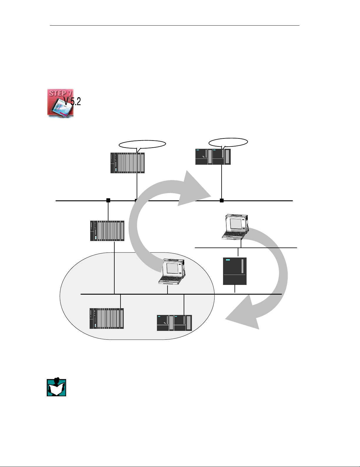
Industrial Ethernet is integrated in the SIMATIC NET concept that allows
comprehensive networking of the management, cell and field levels in conjunction
with PROFIBUS and the AS-interface (AS-i).
Figure 1-1 Industrial Ethernet in the SIMATIC NET Concept
Network Access
Industrial Ethernet is accessed using the CSMA/CD (Carrier Sense Multiple
Access with Collision Detection) network access technique specified in
IEEE 802.3.
Industrial
Ethernet
(IEEE 802.3)
PROFIBUS
(EN 50170 Vol. 2 PROFIBUS)
AS-Interface
(AS-i, Actuator-Sensor Interface)
16
SIMATIC NET NCM S7 for Industrial Ethernet
C79000–G8976–C129–07
Release 6/2003
Page 17

Communication via Ethernet CPs in S7 Stations
1.2 SIMATIC S7 Communication with S7 Ethernet CPs
Types of Communication
The Ethernet CP for SIMATIC S7 supports the following types of communication
depending on the CP type:
Ethernet CP
S7/M7-400
Possible types of communication
S PG/OP communication
S S7 communication
S S5-compatible communication
S PROFInet communication
Ethernet CP
S7-300
Interfaces / Services /
Protocols
with the protocols
– ISO
– TCP/IP (RFC 1006)
with the SEND / RECEIVE interface and the protocols
– ISO Transport
– ISO-on-TCP (TCP/IP with RFC 1006)
– TCP
– UDP
– E-mail
with FETCH / WRITE services and the protocols
– ISO Transport
– ISO-on-TCP
– TCP
with the protocols
– TCP
S HTML process control with
web browser
S File management and file
access with FTP
S PG/OP communication
PG/OP communication is used to download programs and configuration data,
to run tests and diagnostic functions, and to control and monitor a plant from
OPs.
SIMATIC NET NCM S7 for Industrial Ethernet
Release 6/2003
C79000–G8976–C129–07
with the protocols
– HTTP / IP protocol
with the protocols
– FTP / IP protocol
17
Page 18

Communication via Ethernet CPs in S7 Stations
S S7 communication
S7 communication forms a simple and efficient interface between SIMATIC S7
stations and PGs/PCs using communication function blocks.
S S5-compatible communication with SEND/RECEIVE interface
Depending on the CP type, the SEND/RECEIVE interface allows
program-controlled communication on a configured connection from a SIMATIC
S7 PLC to another SIMATIC S7 PLC, to a SIMATIC S5 PLC, to PCs/PGs, and
to any other station.
Depending on the CP type, the following communications services are available
on the SEND/RECEIVE interface:
– ISO Transport
optimized for top performance at the self-contained manufacturing level
– TCP/IP for internetwork communication with
ISO-on-TCP connections (RFC 1006), TCP connections and
UDP datagram service (including broadcast / multicast).
– Sending E-mail
The controller is capable of sending messages triggered by process events
(refer to the IT-CP manual for details /5/).
S S5-compatible communication with FETCH/WRITE services (server)
The FETCH/WRITE services (server) allow direct access to the system
memory areas on the SIMATIC S7 CPU from SIMATIC S5, SIMATIC PC
stations, or from devices of other ranges.
Depending on the CP type, the following communications services are available
for FETCH/WRITE access:
– ISO Transport
optimized for top performance at the self-contained manufacturing level
– TCP/IP for internetwork communication with
ISO-on-TCP connections (RFC 1006), TCP connections.
S PROFInet communication
PROFInet is a standard of the PROFIBUS Users organization defining a
heterogeneous communications and engineering model.
An S7-300 station equipped with a CP capable of PROFInet can be
interconnected as a PROFInet component in SIMATIC iMap.
TCP connections are used for the PROFInet communication.
18
For more detailed information on PROFInet, refer to /23/.
S HTML process control
With an IT-CP, use the supplied functions and HTML pages to query important
system data using a Web browser (you should also refer to the instructions on
the IT-CP /5/).
SIMATIC NET NCM S7 for Industrial Ethernet
C79000–G8976–C129–07
Release 6/2003
Page 19
Communication via Ethernet CPs in S7 Stations
S File management and file access with FTP
The IT-CP (S7-400 / S7-300) provides additional functions for FTP services.
You can use your S7 station both as an FTP client and as an FTP server (refer
to the manual of the IT-CP /5/).
– S7 Station as FTP Client
You can transfer data blocks from or to a file server.
– S7 Station as FTP Server
Another station, for example, a PC transfers data blocks to or from the S7
station the file system on the IT-CP.
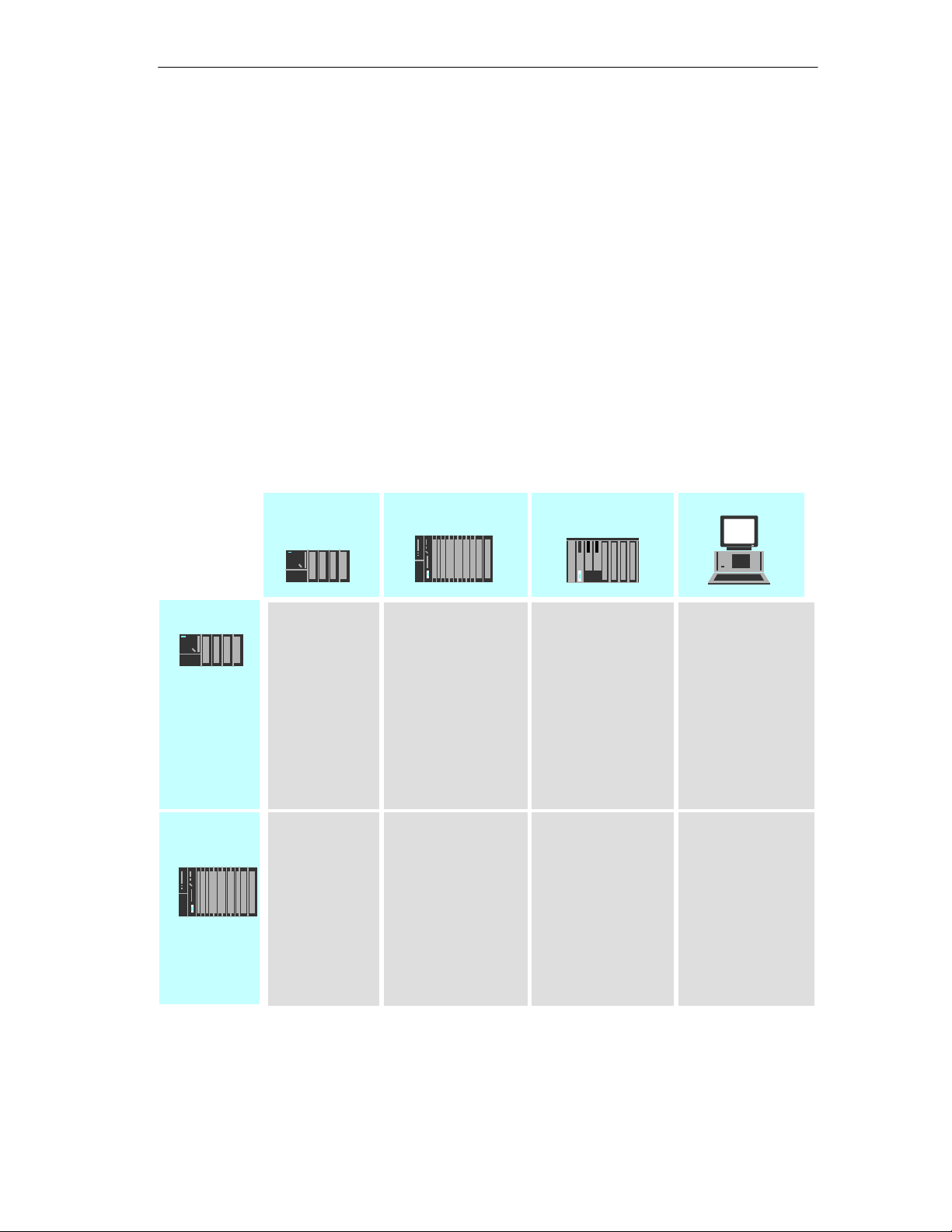
Possibilities for Communication between Device Types
The possible communication available with the types of communication listed
above is shown in the following table:
S7-300
S7/M7-400
S7 communication
SEND/RECEIVE
PROFInet
S7 communication
SEND/RECEIVE
1) PC only as client
S7-300
S7-400
S7 communication SEND/RECEIVE
SEND/RECEIVE
S7 communication
SEND/RECEIVE
FTP services
S5-115 to -155U/H
FETCH/WRITE
SEND/RECEIVE
FETCH/WRITE
PC station
PG/OP
communication
S7 communication
SEND/RECEIVE
FETCH/WRITE
HTML process
control
PROFInet
FTP services
PG/OP
communication
S7 communication
SEND/RECEIVE
FETCH/WRITE
HTML process
control
FTP services
1)
1)
1)
1)
SIMATIC NET NCM S7 for Industrial Ethernet
Release 6/2003
C79000–G8976–C129–07
19
Page 20

Communication via Ethernet CPs in S7 Stations
Configuration and Diagnostics
To connect and configure the Ethernet CP, you require the STEP 7 configuration
software and the SIMATIC NET NCM S7 for Industrial Ethernet option.
NCM S7 for Industrial Ethernet is installed as a STEP 7 option and is therefore
integrated in STEP 7.
NCM S7 for Industrial Ethernet also provides a wide range of diagnostic functions
for the various types of communication.
When configuring PROFInet communication, you also use the engineering tool
SIMATIC iMap; for detailed information on SIMATIC iMap, refer to the manual
Component based Automation – Configuring Plants with SIMATIC iMap /23/.
Programmed Connections
In some situations, it is an advantage to set up communication connections not
over the configuration interface of STEP 7 but program-controlled by specific
V 5.2.1
applications.
As of STEP 7 V5.2 SP1, a function block is available for these applications that
allows flexible transfer of data blocks with configuration data to an Ethernet CP.
20
SIMATIC NET NCM S7 for Industrial Ethernet
C79000–G8976–C129–07
Release 6/2003
Page 21

Communication via Ethernet CPs in S7 Stations
1.3 PG/OP Communication via Industrial Ethernet
Application
PG/OP communication provides functions that are already integrated in every
SIMATIC S7/M7/C7 device.
A distinction must be made between the following two types of function:
S PG communication
PG communication with STEP 7 PLCs on Industrial Ethernet means the
following:
– You can use the complete range of functions of STEP 7 on Industrial
Ethernet.
– You can use programming, diagnostic, operating and monitoring functions on
all modules in the SIMATIC S7 PLC via Industrial Ethernet.
S OP Operation
PG/OP communication on Industrial Ethernet allows the operation and
monitoring of all modules in a SIMATIC S7 PLC using operator interface
systems (TD/OP).
The Ethernet CP acts as a “communications relay” that relays the PG/OP
communication via Industrial Ethernet.
SIMATIC NET NCM S7 for Industrial Ethernet
Release 6/2003
C79000–G8976–C129–07
21
Page 22
Communication via Ethernet CPs in S7 Stations
Operator
interface
functions
Ethernet attachment
S7 – 400
Ethernet CP
OP
S7 – 300
PC with Ethernet CP
STEP 7
NCM S7
Create configuration data for
every CP and download to the
Ethernet CPs
Ethernet
Ethernet CP
S7 – 400
Modem /
ISDN
WAN *
* only TCP/IP
Figure 1-2 Configuration for PG/OP Operation
22
Ethernet CP
SIMATIC NET NCM S7 for Industrial Ethernet
C79000–G8976–C129–07
Release 6/2003
Page 23

Communication via Ethernet CPs in S7 Stations
1.3.1 PG Communication with STEP 7 over Industrial Ethernet
Requirements for PG Communication
PG communication is possible when the following requirements are met:
S An Ethernet CP is installed in the PG or engineering station or there is a
modem/ISDN interface for remote access.
S The Ethernet CP must have an address (default MAC address or set the IP
address).
Networking the PG / Engineering Station
Depending on the configuration of the PG or Engineering Station, the following two
situations are possible when using PG communication:
S PG / Engineering Station in the Configured Mode
If you select this configuration when you commission the PG / engineering
station, the interfaces of the communication modules you are using are already
known. The option in “Set PG/PC Interface” is automatically set to
“PC-internal”.
Once you have downloaded this configuration to your PG / engineering station,
you can exchange PG functions with the accessible nodes in the network with
STEP 7 without requiring any further settings.
S PG / Engineering Station in PG Operation
If your PG or engineering station is configured for this mode, you must specify the
interface on the PG or engineering station explicitly with “Set PG/PC Interface”.
Follow the steps outlined below:
1. Open the “Set PG/PC Interface” dialog box in the Windows Control Panel.
2. Set the PG/PC interface according to the CPs available on your PG and
according to the bus attachment (interface parameter assignment used).
For more detailed information on the topic of PG operation and engineering station,
refer to /4/.
SIMATIC NET NCM S7 for Industrial Ethernet
Release 6/2003
C79000–G8976–C129–07
23
Page 24

Communication via Ethernet CPs in S7 Stations
1.3.2 OP Operation: Connecting Operator Interface Devices via Industrial Ethernet
Requirements
Operation allowing operator interface functions is possible when the following
conditions are met:
S The operator interface device has:
– an Ethernet CP installed
– SOFTNET S7 for Ind. Ethernet or S7-1613/ WIN 95, WIN NT, MS-DOS,
Windows installed.
S The CPs in the S7 stations are supplied with a MAC/IP address (use the default
MAC address or set an IP address).
Procedure
To be able to use S7 communication, address the required module in the SIMATIC
S7 PLC on your operator interface system.
For more detailed information, refer to the description of your operator interface
system.
24
SIMATIC NET NCM S7 for Industrial Ethernet
C79000–G8976–C129–07
Release 6/2003
Page 25
Communication via Ethernet CPs in S7 Stations
1.4 S7 Communication on Industrial Ethernet
Application
S7 communication via Industrial Ethernet allows program-controlled
communication using communication SFBs/FBs via configured S7 connections.
Per job, up to 64 Kbytes of user data can be transmitted.
The Ethernet CP acts as an “S7 communication relay” by passing on the S7
functions via Industrial Ethernet (see /8/). Depending on the configuration of the
Ethernet CP, data transfer is on the basis of the ISO transport or the ISO-on-TCP
protocol (TCP/IP with RFC 1006).
From the perspective of the user, S7 communication is identical over PROFIBUS
and Industrial Ethernet.
Nodes
Two situations can occur depending on device type and plant configuration:
S Client and server functionality at both ends
S7 connections can be operated between the following nodes with the entire
functionality of S7 communication:
– between S7 stations S7-300 and S7-400;
– between S7 stations and PC/PG stations with an Ethernet CP.
S7 – 400
Ethernet
Ethernet CP
S7 – 300
Ethernet CP
PUT / GET
BSEND / BRECV
WAN *
USEND / URECV
M7
* only TCP/IP
PC/PG with Ethernet CP
Figure 1-3 Nodes Communicating on S7 Connections over Industrial Ethernet
SIMATIC NET NCM S7 for Industrial Ethernet
Release 6/2003
C79000–G8976–C129–07
S7 – 300 / 400
25
Page 26
Communication via Ethernet CPs in S7 Stations
S Client and server functionality at one end only (S7 connections
configured at one end)
In the following situations, write and read functions can be implemented with
PUT / GET:
– S7 communication over router
PG/PC stations can access S7 stations if the PG/PC stations are connected
to a different subnet or subnet type (PROFIBUS / Ethernet) via routers (for
example, an IE/PB Link); in this case, S7 stations are servers.
S7 communication is possible over a gateway.
Ethernet
S7 – 400
PROFIBUS
Ethernet CP
PC/PG Station
S7 – 300
PUT / GET
Ethernet
Ethernet CP
PC/PG Station
IE/PB Link
PUT / GET
Figure 1-4 PC/PG station communicates over a gateway with S7 stations on an underlying PROFIBUS
or Ethernet
For more detailed information on the features supported by your Ethernet CP, refer
to the manual /1/.
26
SIMATIC NET NCM S7 for Industrial Ethernet
C79000–G8976–C129–07
Release 6/2003
Page 27

Communication via Ethernet CPs in S7 Stations
Configuring S7 Connections
Create S7 connections to use S7 communication for data exchange between two
SIMATIC S7 stations.
For more detailed information, refer to the STEP 7 Description /6/ /8/.
Notice
S7 connections via routers are supported only within a STEP 7 project but not
between partners in different STEP 7 projects of a multiproject!
Interface in the User Program of the S7 Station
You use SFBs (for S7-400) and FBs (for S7-300) in the user program.
Block Type Client Server Described in
SFB / FB12 BSEND x – STEP 7
SFB / FB13 BRCV x
SFB / FB15 PUT x –
SFB / FB14 GET x –
SFB / FB8 USEND x –
SFB / FB9 URCV – x
SFC / FC62 CONTROL (S7-400) /
C_CNTRL (S7-300)
x x
Documentation /9/
1)
1)
2)
1) you do not need to configure a connection on the server
2) for S7-300
Notice
Please remember the following points regarding data consistency in your user program:
In the CPU of the S7 station, the read or written information is taken from the S7
user program into the operating system or copied from the operating system to the
S7 user program in blocks of 8 or 32 bytes (depending on the firmware version).
If information in the word or double-word format is located across such boundaries, data inconsistency may arise during transmission using S7 communication!
For more detailed information, refer to the STEP 7 documentation /9/.
SIMATIC NET NCM S7 for Industrial Ethernet
Release 6/2003
C79000–G8976–C129–07
27
Page 28

Communication via Ethernet CPs in S7 Stations
Notes on S7 Communication between PC/PG Station and S7 Station
Applications in a PC/PG station communicate with the S7 station over an OPC
interface or SAPI-S7 interface for operator intervention, monitoring and control.
The S7 stations use the integrated communication SFBs/FBs (client and server
functionality at both ends).
The following general requirements must be met by a PC/PG station for S7
communication:
S On the PC/PG:
– an Ethernet CP installed
– there is an interface for S7 communication installed: SOFTNET S7 for Ind.
Ethernet or S7-1613/ WIN 95, WIN NT, MS-DOS, Windows.
S The CPs in the S7 stations are supplied with a MAC/IP address (use the default
MAC address or set an IP address).
To use S7 communication with the SIMATIC S7 PLC from a PC, address the
required CPU module in the SIMATIC S7 PLC that you want to communicate
with in your PC application.
S7 Communication via Routers (one-sided Client and Server Functionality)
It is possible to reach the S7 station from an application (OPC server) of the
PC/PG station that is attached to another subnet. The subnets must be connected
over a router such as the IE/PB Link. An S7 station or a PC connected to both
subnets can also serve as a router.
In this configuration, the S7 station can only be addressed by the PC/PG station as
a communications server on S7 connections configured at one end.
The requirements for the configuration of the PC/PG station are identical to those
for operation in the same subnet (see above); the CP in the PC/PG station must
also have routing capability.
In this situation, configure a one-ended S7 connection to the PC/PG station in the
other subnet for the PC/PG station in STEP 7 NetPro. You can then access data in
the S7 station in your user program using the functions PUT (writing) and GET
(reading).
28
SIMATIC NET NCM S7 for Industrial Ethernet
C79000–G8976–C129–07
Release 6/2003
Page 29

Communication via Ethernet CPs in S7 Stations
1.5 S5-compatible Communication (SEND/RECEIVE
1
Interface)
Application
Using the SEND/RECEIVE interface, your S7 user program has access to
S5-compatible communication with configured transport connections.
Data transmission on a configured transport connection is suitable for
S the reliable transmission of related blocks of data between two Ethernet nodes
using
– TCP (see /17//19//20/) with ISO-on-TCP connection (see /18/) or TCP
connection;
– ISO transport connection
S simple (unacknowldeged) transfer of related blocks of data (datagram service)
between two Ethernet nodes with UDP (User Datagram Protocol) on IP.
)
The SEND/RECEIVE interface is also suitable for sending E-mail (refer to the
manual for the IT-CP /5/).
For TCP applications, there is an active network with IP protocol (see /20/).
ISO Transport Connection
ISO transport provides services for the reliable transfer of data on configured
connections. Due to the segmentation of the data, large amounts of data can be
transmitted.
Transmission reliability is extremely high due to automatic repetition and additional
field check mechanisms. The communications partner confirms reception of data
and the sender receives a return value on the SEND/RECEIVE interface.
ISO transport is operated only on Industrial Ethernet and is optimized for
high-performance operation at the self-contained manufacturing level.
1The previous name of the SEND/RECEIVE interface was S5S5 connections
SIMATIC NET NCM S7 for Industrial Ethernet
Release 6/2003
C79000–G8976–C129–07
29
Page 30

Communication via Ethernet CPs in S7 Stations
IP (Internet Protocol)
For internetwork data transmission, the following services are available with
suitable CPs such as the CP 443-1:
S ISO-on-TCP connection
ISO-on-TCP is intended for reliable, internetwork data transmission.
The ISO-on-TCP service corresponds to the TCP/IP standard (Transmission
Control Protocol/Internet Protocol) with the RFC 1006 extension according to
layer 4 of the ISO reference model (see /18/).
RFC 1006 extends the TCP protocol by allowing the transmission of blocks of
data (“messages”) assuming that both partners support RFC 1006.
Transmission reliability is extremely high due to automatic repetition and
additional field check mechanisms. The communications partner confirms
reception of data and the sender receives a return value on the
SEND/RECEIVE interface.
S TCP connection
When using the SEND/RECEIVE interface on TCP connections, the Ethernet
CP supports the socket interface (for example, Winsock.dll) to TCP/IP found on
almost every system (PC or other system).
TCP is intended for reliable internetwork data transmission.
The TCP service complies with the TCP/IP standard (Transmission Control
Protocol/Internet Protocol; see /18/).
S UDP connection
UDP is intended for simple internetwork data transmission without confirmation.
If the connection is suitably configured, broadcast and multicast frames can
also be sent on UDP connections.
To avoid overload due to high broadcast load, the CP does not allow reception
of UDP broadcasts. As an alternative, use the multicast function over a UDP
connection. This allows you to register the CP as a node in a multicast group.
SEND/RECEIVE
Interface
Data transfer is triggered by the user program. The interface to the user program in
the SIMATIC S7 is formed by special SIMATIC S7 blocks of the type FC
(functions).
30
SIMATIC NET NCM S7 for Industrial Ethernet
C79000–G8976–C129–07
Release 6/2003
Page 31

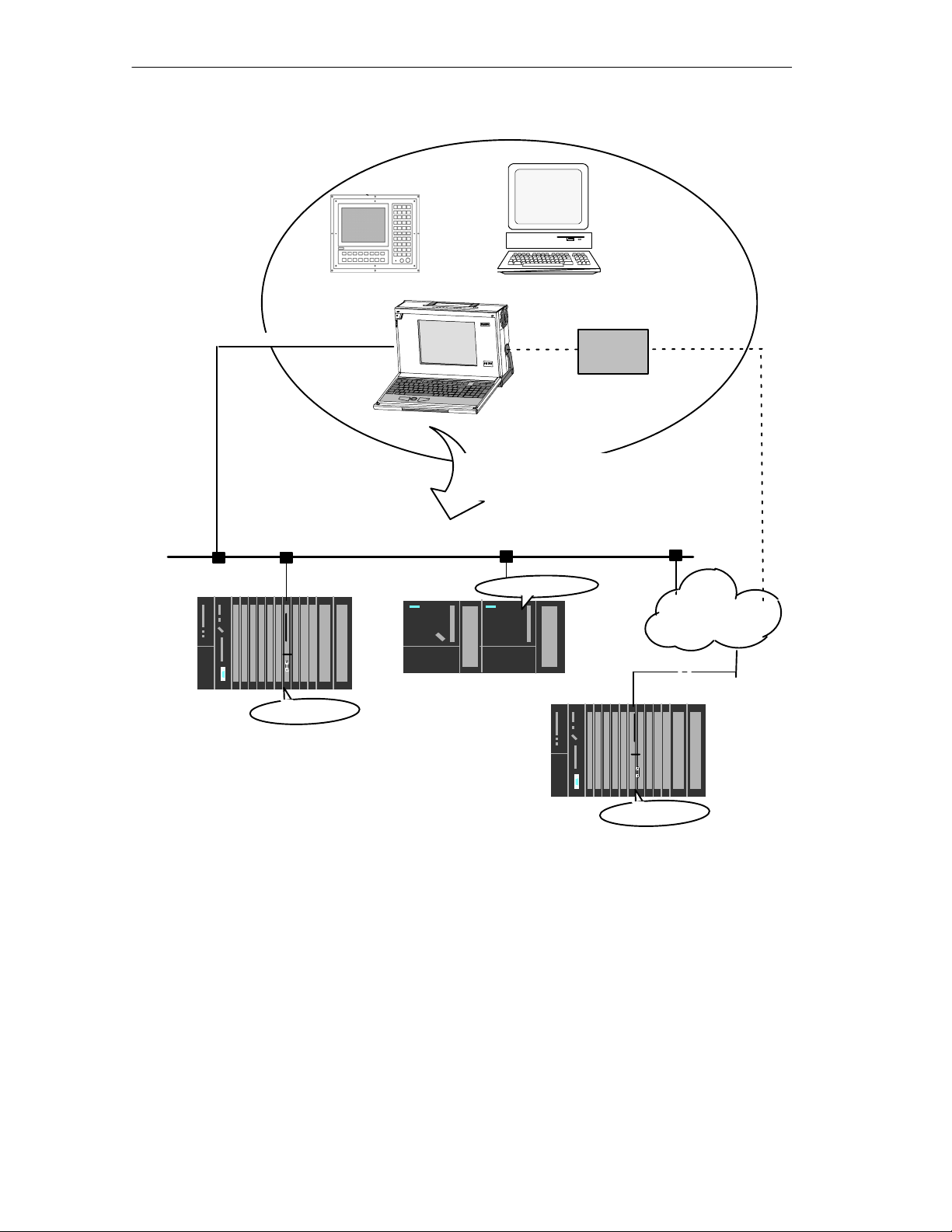
Stations
Communication via Ethernet CPs in S7 Stations
The SEND/RECEIVE interface allows program-controlled communication on
Industrial Ethernet between the SIMATIC S7 PLC and the following:
S SIMATIC S7 PLC with Ethernet CP
S SIMATIC S5 PLC with Ethernet CP
S PC/PG with Ethernet CP
S Other station with Industrial Ethernet attachment
S7 – 400
Ethernet
SIMATIC S5
with Ethernet CP
Ethernet CP
WAN
Internet
Router
S7 – 300
Other station with
Ethernet attachment
only TCP/IP
Ethernet CP
D D D
D D D
D D DD D D
PG/PC with Ethernet
attachment
Figure 1-5 SIMATIC S7 PLC with Possible Communications Partners on the SEND/RECEIVE Interface
SIMATIC NET NCM S7 for Industrial Ethernet
Release 6/2003
C79000–G8976–C129–07
31
Page 32

Communication via Ethernet CPs in S7 Stations
1.6 FETCH/WRITE Services (Server)
Application
In addition to the SEND/RECEIVE interface, the FETCH/WRITE functionality
provides further services for S5-compatible communication on configured transport
connections.
The FETCH/WRITE interface is used primarily to attach SIMATIC S7 to SIMATIC
S5 and to other non-S7 stations (for example PCs).
S FETCH
The partner on the connection (SIMATIC S5 or non-S7 station) can read
system data on the SIMATIC S7 PLC.
S WRITE
The partner on the connection (SIMATIC S5 or non-S7 station) can write
system data on the SIMATIC S7 PLC.
From the point of view of the SIMATIC S7 PLC, this is a passive communication
function; the communications partner initiates the connection establishment.
For further information, refer to the system documentation of the SIMATIC S5 PLC
or the non-S7 station you are using.
Connection Types
To access a station with FETCH or WRITE functions, a FETCH passive or WRITE
passive connection must be configured. The following types are possible:
S ISO Transport
S ISO-on-TCP
S TCP
Coordinating Access Using the User Program
To coordinate access, you can use the FCs AG_LOCK and AG_UNLOCK.
With these FCs, you can coordinate access to system memory areas so that no
inconsistent data are created and transferred.
SIMATIC S5
32
On the SIMATIC S5 station, the FETCH/WRITE services are configured and
started by READ ACTIVE/PASSIVE and WRITE ACTIVE/PASSIVE.
SIMATIC NET NCM S7 for Industrial Ethernet
C79000–G8976–C129–07
Release 6/2003
Page 33

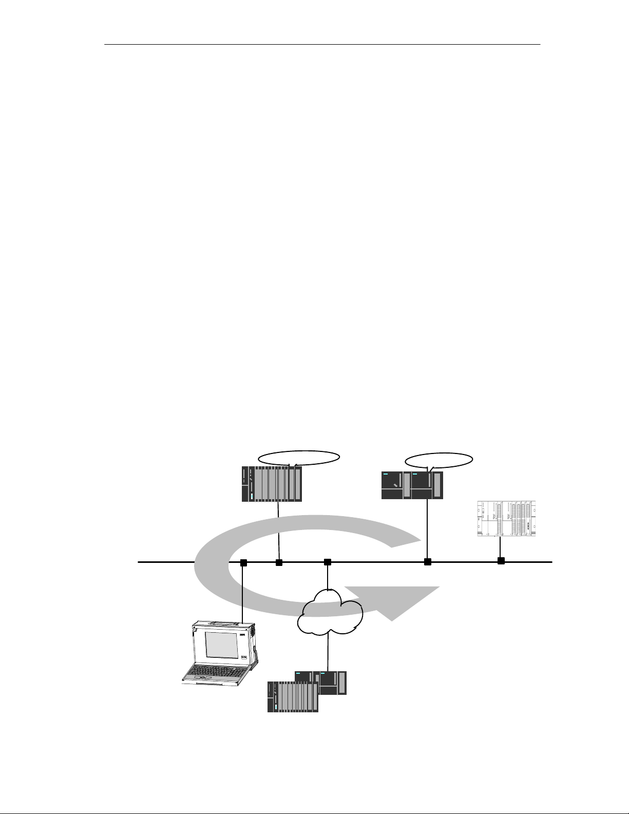
Communication via Ethernet CPs in S7 Stations
1.7 Networking Stations with STEP 7
Configuring
To allow stations to communicate with each other the networks must be configured
in the STEP 7 projects.
Configuring a network or subnet involves the following:
1. You create one or more subnets of the required subnet type in the project.
2. You select the properties of the subnet. Normally the default settings are
adequate.
3. You connect the station “logically” to the subnet.
4. You set up connections for communication.
Networking in a Multiproject
Tools
STEP 7 as of Version V5.2 supports configuration in a multiproject.
Using a multiproject, for example, you can create a project for distributed editing by
various editors and distribute the stations to the projects according to their editors.
To allow this, functions are available for branching and merging (sub) projects.
Interproject subnets and connections can be created.
The SIMATIC Manager provides convenient tools for configuring and documenting
networks (also graphically with NetPro).
The chapter describing network configuration in /6/ and the online help system also
contain information about configuring SIMATIC S7 networks.
SIMATIC NET NCM S7 for Industrial Ethernet
Release 6/2003
C79000–G8976–C129–07
33
Page 34

Communication via Ethernet CPs in S7 Stations
Variants
Before configuring networks with STEP 7, you should be aware of the various
configurations possible in the STEP 7 project. The following configurations are
typical for stations networked with CPs:
Variant (examples) Characteristics/Configuration
1 1 subnet – 1 project
2 Additional SIMATIC S5 stations and stations with equipment of other vendors
3 2 or more subnets – 1 project
4 1 subnet – more than one project
5 More than one subnet – more than one project
6 Internetwork connections (TCP)
These variants will be used as a basis to illustrate how real configurations can be
created in STEP 7 projects.
34
SIMATIC NET NCM S7 for Industrial Ethernet
C79000–G8976–C129–07
Release 6/2003
Page 35

Communication via Ethernet CPs in S7 Stations
1.7.1 Network/Project Variant: One Subnet – One Project
Configuration of the System
In the simplest case, your system consists of SIMATIC S7 stations connected by
one subnet, for example of the type Industrial Ethernet.
View in a STEP 7 Project
You create an Industrial Ethernet object in the STEP 7 project. Stations created
in the same project refer to this object as soon as they are configured as
network nodes.
System
“Production”
Ethernet (1)
S7-400/1
S7-300/1
S7-300/2
SIMATIC NET NCM S7 for Industrial Ethernet
Release 6/2003
C79000–G8976–C129–07
35
Page 36

Communication via Ethernet CPs in S7 Stations
1.7.2 Network/Project Variant: SIMATIC S5 and Non-SIMATIC Devices on the Subnet
Configuration of the System
In addition to SIMATIC S7 stations, SIMATIC S5 stations and non-SIMATIC
devices can be included in your system.
S7-400/1
S7-400/1
S7-300/1
System
“Production”
Ethernet (1)
Ethernet (1)
S7-300/1
Non-SIMATIC
View in a STEP 7 Project
SIMATIC S5 stations you intend to include in the communication can be
selected directly. Non-SIMATIC devices must be entered in the configuration as
Other stations.
SIMATIC S5
S7-300/2
36
SIMATIC NET NCM S7 for Industrial Ethernet
C79000–G8976–C129–07
Release 6/2003
Page 37

Communication via Ethernet CPs in S7 Stations
1.7.3 Network/Project Variant: Two or More Subnets – One Project
Configuration of the System
Due to the different tasks of the stations or due to the extent of the system it may
be necessary to operate more than one network.
S7-400/1
System
“Production and Management Level”
View in a STEP 7 Project
You can create the subnets in one STEP 7 project and configure the stations for
communication.
Ethernet (1)
Ethernet CP
S7-400/2
PROFIBUS CP
PROFIBUS (1)
S7-300/1 S7-300/2
This representation illustrates the following:
S More than one subnet can be managed in one project.
S Each station is created once in the project.
S Each station can be assigned to more than one subnet by assigning its CPs to
different subnets.
SIMATIC NET NCM S7 for Industrial Ethernet
Release 6/2003
C79000–G8976–C129–07
37
Page 38

Communication via Ethernet CPs in S7 Stations
1.7.4 Network/Project Variant: One Subnet – More Than One (Sub)Project
Configuration of the System
In complex networked systems, during configuration it is sometimes more efficient
to manage plant sections in different (sub) projects.
The situation can arise that communication takes place over an interproject subnet
and that interproject connections must then also be created.
Example:
System section
System section
“Production 1”
“Production 2”
S7 400/1
S7 300/1 S7 – 300/2
Organization in a Multiproject
User-friendly and consistent configuration of such communication is supported in
STEP 7 as of Version V5.2 with the multiproject.
The functions for multiprojects in STEP 7 allow the following:
S Several projects can be managed in one multiproject and edited separately
S Projects can be branched and merged
Two different strategies can be distinguished in a multiproject:
S Several employees work at the same time on a multiproject in a networked
environment. The projects of the multiproject are in different network folders. In
this case, all connection partners are available for configuring connections.
S7 – 400/2
Ethernet (1)
S7 – 300/3
38
S One employee manages the multiproject centrally. This person creates the
structures for projects (when necessary locally) and contracts individual projects
out for external editing. The central configuration engineer then returns these
projects to the multiproject and synchronizes the interproject data with system
support and where necessary executes the required interproject functions.
SIMATIC NET NCM S7 for Industrial Ethernet
C79000–G8976–C129–07
Release 6/2003
Page 39

Communication via Ethernet CPs in S7 Stations
In this case, agreement is necessary, for example, regarding the assignment of
connection names because it will be far easier when synchronizing the projects
to bring connections with identical connection names together.
The topic of multiprojects is dealt with in detail in the STEP 7 basic help.
Here, you will find information on the following topics:
S Requirements for interproject functions
S How to create multiprojects
S How to create a new project in a multiproject
S How to separate a project from a multiproject
S How to include projects in the multiproject
S How to synchronize projects in a multiproject
S Moving stations within a multiproject (when a station is moved from one project
of a multiproject to another project of the same multiproject (for example using
drag & drop), the interproject connections are retained)
S Possible problems in distributed projects and tips on how to avoid them
Possibilities for stations outside the current project
The addition of the multiproject functionality means that the following situations can
arise:
S Connection to a partner in an unknown project
The new multiproject functionality allows you to create a connection to a partner
in an unknown project. In this case, you can specify a connection name as a
reference in the properties dialog of the connection. When the projects are
merged, STEP 7 then supports you with automatic synchronization of the
separately configured connections.
The connection remains unspecified until the projects have been merged and
the connections synchronized. Only following this synchronization can the
configuration data be downloaded to the local station without inconsistencies.
You should therefore use this variant when you know that the projects will be
merged in a multiproject.
S Specified connections with representative objects
To allow you to create specified connections to stations in a different project (for
example production 2) or that are not managed with STEP 7, you can configure
these stations as other stations(example in the project production 1).
This makes it possible to create consistent, fully specified configuration data
and to download it to the local station.
It is also possible to create specified connections between these stations in
different, independent projects. The stations can then communicate
immediately over the created connections after the configuration data have
been downloaded.
SIMATIC NET NCM S7 for Industrial Ethernet
Release 6/2003
C79000–G8976–C129–07
39
Page 40

Communication via Ethernet CPs in S7 Stations
Use this variant when you want to operate projects separately due to the
complexity.
Stations of the type SIMATIC S5 function in just the same way as
representative objects.
Merging Projects in the Multiproject:
If you have used the multiproject functions allowing you to use connections to a
partner in an unknown project, STEP 7 will automatically attempt to synchronize
two separately configured connections.
If you have configured projects with representative objects and want to merge
these projects into a multiproject, you have the following options:
S You can leave the representative objects with the configured connections
unchanged.
S You can reassign the connection partner and then delete the representative
objects.
40
SIMATIC NET NCM S7 for Industrial Ethernet
C79000–G8976–C129–07
Release 6/2003
Page 41

Communication via Ethernet CPs in S7 Stations
1.7.5 Network/Project Variant: Several Subnets in Several (Sub) Projects
Configuration of the System
If several network types need to be used and if these need to be managed in
different projects due to the different tasks of the stations or due to the large span
of the plant, stations can be created as follows:
S Using (sub) projects in the “multiproject”
S by configuring “Other stations / SIMATIC S5” in the other project.
Ethernet (1)
S7 – 400/1
PROFIBUS (1)
Ethernet CP
PROFIBUS CP
S7 – 300/1
Cell level = (sub)project 1
Cell level = (sub)project 2
S7 – 300/2
Organization in a Multiproject
If you use a multiproject organization, follow the steps below to connect the
S7-400/1 station to the PROFIBUS (1) subnet:
Create a subnet of the type PROFIBUS in both subprojects and merge these two
subnets in NetPro.
SIMATIC NET NCM S7 for Industrial Ethernet
Release 6/2003
C79000–G8976–C129–07
41
Page 42

Communication via Ethernet CPs in S7 Stations
Representative Objects for Stations Outside the Current Project
If you do not want to use the multiproject functions, you can fall back on the use of
representative objects as used previously.
To be able to network the representative objects, you must once again create a
subnet of the type PROFIBUS in both projects as shown in the example here.
42
SIMATIC NET NCM S7 for Industrial Ethernet
C79000–G8976–C129–07
Release 6/2003
Page 43

Communication via Ethernet CPs in S7 Stations
1.7.6 Network/Project Variant: Connections between Subnets (TCP/IP)
Configuration of the System
If connections are required to stations on network structures connected by routers
due to the differing tasks of the stations or the large span of the network, the
stations in the other project can be reached by configuring “Other Stations”.
S7 – 400/1
Ethernet CP
Ethernet (1)
WAN
Internet *
View in a STEP 7 Project
If the stations in the two networks are managed in the same project, the
networking appears as shown below in NetPro.
Router *
Ethernet (2)
S7 – 400/2
Ethernet CP
S7 – 300/1
* only TCP/IP
SIMATIC NET NCM S7 for Industrial Ethernet
Release 6/2003
C79000–G8976–C129–07
43
Page 44

Communication via Ethernet CPs in S7 Stations
44
SIMATIC NET NCM S7 for Industrial Ethernet
C79000–G8976–C129–07
Release 6/2003
Page 45

Installing and Starting the Ethernet CP with STEP 7
To attach a SIMATIC station to Industrial Ethernet via the Ethernet CP, configure
the CP with the NCM S7 configuration software. The chapter explains the
following:
S How the CP is configured in the STEP 7 project
S How the various network configurations are managed (setting up access to
other systems)
S How to control and supply the CP with data using NCM S7
You will find further information in the following sources:
S When installing the Ethernet CP, please refer to the instructions in the manual
/1/ supplied with the Ethernet CP. This also contains further information about
the performance of the Ethernet CP .
S For more information about the functions and applications of STEP 7 in which
the NCM S7 option is integrated, please read the following topics:
2
– For using the help functions, read the section Working with STEP 7 in /6/.
– Configuring and assigning parameters to modules in /6/
– Configuring networks in /6/. You will find this information in the online help
with integrated in STEP 7 by selecting Help " Contents.
S You will find examples of configurations in the Primer /3/.
SIMATIC NET NCM S7 for Industrial Ethernet
Release 6/2003
C79000–G8976–C129–07
45
Page 46

Installing and Starting the Ethernet CP with STEP 7
2.1 General Information About the NCM S7 for Industrial Ethernet Option
Installation
Please follow the instructions in the README file when installing the NCM S7 for
Industrial Ethernet option on your PG/PC under STEP 7.
Functions
NCM S7 consists of the following:
S CP-specific index dialogs that you call using the properties dialog box of the
modules.
S Dialogs for the connection configuration
S Diagnostic functions that you obtain as follows:
Operation
– Using the “Diagnostics” tab in the properties dialog
– Using the standard Start menu of Windows with which you can call the
SIMATIC program group
S Functions displayed with SIMATIC " NCM... in the Start menu of Windows:
– Diagnostics
– Help for functions (FCs)
– “Readme” file with current information about NCM
– Firmware loader
Operating and handling the software package is as explained in the STEP 7 user
manual /6/.
46
SIMATIC NET NCM S7 for Industrial Ethernet
C79000–G8976–C129–07
Release 6/2003
Page 47

2.2 Procedure
A CP is managed in an S7 project just as the other modules. You use STEP 7 to
configure the hardware and create and manage the user software (see /6/).
Configuring a CP involves the following basic steps (the broken lines indicate
options):
Create the Industrial Ethernet subnet (see 2.2.1)
Enter the Ethernet CP in the hardware configuration
Installing and Starting the Ethernet CP with STEP 7
Check or set the network properties
(see 2.2.2)
Attach the Ethernet CP to the Ethernet subnet
(see 2.2.2)
Display the network attachments of a station (see 2.2.3)
Make further CP settings (see 2.2.4)
Configuring communication connections (Chap. 4)
– S7 connections /6/
– ISO transport connections
– ISO-on-TCP connections
– TCP connections
– UDP
Configuration data in
the STEP 7 project
alternative:
Program communication
connections
(see Chapter 5)
Programming the
SEND/RECEIVE interface
(see Chapter 3)
User programs in the STEP
7 project
Download the configuration to the PLC (see 2.4).
SIMATIC NET NCM S7 for Industrial Ethernet
Release 6/2003
C79000–G8976–C129–07
47
Page 48

Installing and Starting the Ethernet CP with STEP 7
2.2.1 Creating an Industrial Ethernet Subnet
Aims
To be able to attach the SIMATIC stations to a subnet, you create the subnet in
your project. This means that all the parameters for the entire subnet are managed
centrally.
Procedure
It is advisable to create the subnet before you configure the stations since the
assignment of the SIMATIC stations is then performed largely automatically.
It is also possible to create the subnet at a later point in time when configuring a
CP. This is explained in more detail later in the chapter.
Follow the steps outlined below:
1. Select the project in the SIMATIC Manager.
2. Select Insert " Subnet " Industrial Ethernet.
Result: An object of the type network is created in the project. This allows all
the SIMATIC stations created in the project to be attached to this subnet.
Figure 2-1 Project with Assigned Ethernet Network
48
SIMATIC NET NCM S7 for Industrial Ethernet
C79000–G8976–C129–07
Release 6/2003
Page 49

Installing and Starting the Ethernet CP with STEP 7
3. If you prefer a NetPro graphic network display, select the network object
“Ethernet” and confirm with Edit " Open Object.
Figure 2-2 Graphic Network Representation (here showing stations not yet networked)
From this graphic representation, you can also activate all the functions for
networking and configuring connections with the Ethernet CPs.
You can also create the subnets in NetPro! Open the catalog using the menu
command Insert " Network Objects.
Organization in a Multiproject
If you use the multiproject form of organization, this has the following effects when
creating subnets.
You create subnets initially in the subprojects as described above. To be able to
network S7 stations, you will, for example, need to create a suitable subnet of the
type Industrial Ethernet in each subproject.
If this is physically a subnet that extends beyond the boundaries of the subproject,
you should first merge the subnets before configuring the communication
connections between the S7 stations.
If you do not merge the subnets, NetPro assumes that you are connecting the
subnets via routers and displays warning messages to this effect.
Properties of Merged Subnets (Multiproject)
When you merge subnets, transferable subnet properties such as the subnet ID of
the master subnet will be transferred to the other subnets of the group.
Some parameters relate specifically to a subproject and remain unchanged; these
include, for example, descriptive parameters such as the name, author, and any
comments.
SIMATIC NET NCM S7 for Industrial Ethernet
Release 6/2003
C79000–G8976–C129–07
49
Page 50

Installing and Starting the Ethernet CP with STEP 7
Notice
Preserving Consistency in Merged Subnets
After merging the subnets, you should check the consistency throughout the multi-
project using the menu command Network > Check Interproject Consistency in
NetPro to make sure that there is consistency throughout the multiproject. This
check detects, for example, S7 subnet IDs that are not unique within the multiproject.
50
SIMATIC NET NCM S7 for Industrial Ethernet
C79000–G8976–C129–07
Release 6/2003
Page 51

Installing and Starting the Ethernet CP with STEP 7
2.2.2 Entering an Ethernet CP in the Hardware Configuration
Procedure
By installing and assigning the Ethernet CP in the rack of a SIMATIC station, you
establish the logical attachment between the Internet CP and the subnet.
1. Select the station in your project that you want to attach to Industrial Ethernet
using an Ethernet CP.
2. Select the CP in the hardware configuration just like any other module by
selecting it in the hardware catalog and then selecting the slot in the rack.
You select CPs in the hardware catalog using a short text and the order
number. Once you have installed NCM S7, the CPs are available in the catalog.
Result: The CP is assigned to the SIMATIC station.
For information about the permitted slots, refer to /1/.
How to configure a module with STEP is described in detail in /6/.
SIMATIC NET NCM S7 for Industrial Ethernet
Release 6/2003
C79000–G8976–C129–07
51
Page 52

Installing and Starting the Ethernet CP with STEP 7
Subnet Attachment
To allow you to activate the network attachment of the Ethernet CP, the SIMATIC
Manager displays the following dialog:
52
SIMATIC NET NCM S7 for Industrial Ethernet
C79000–G8976–C129–07
Release 6/2003
Page 53

Installing and Starting the Ethernet CP with STEP 7
Note
You can open the dialog for setting the interface at any time from the Properties
dialog of the CP in the “General” tab.
1. If you have not yet created a subnet in the project or have not yet created the
selected subnet, you can now create a subnet. To do this, select the “New”
button.
Result: An object of the type network is created in the project.
2. Check the addresses and if necessary change them. The system enters the
next free address automatically.
You will find detailed information on the address ranges in the online help.
Please note the following additional information:
– MAC address
The latest Ethernet CPs are supplied with a default MAC address (address
printed on the module). To be sure that you have a unique address
assignment, do not enter a MAC address in the configuration (the option is
deactivated). This means that the module automatically uses the factory-set
address. If you want to use ISO services, we recommend that you enter the
address printed on the module in the configuration.
Note
The “IP address” and “Subnet mask” input fields have no significance for ISO
transport (option “IP protocol being used”).
3. Select the required subnet type in the “Subnet” list box.
4. You can display the properties dialog box for the selected subnet by clicking the
Properties button.
5. Enter information specific to the subnet node in the “General” tab.
6. You must finally confirm your input with OK, otherwise the networking is not
entered (refer to Point 3.).
Result: The CP is now configured as a network node for the corresponding S7
station.
SIMATIC NET NCM S7 for Industrial Ethernet
Release 6/2003
C79000–G8976–C129–07
53
Page 54

Installing and Starting the Ethernet CP with STEP 7
Setting Addresses in the Configuration and Addressing for the First Time
The address settings described here are made on the CP only after you download
the configuration data.
With the latest Ethernet CPs, the situation is as follows:
To be able to reach the CP using these addresses before you download the
configuration data, you can address the CP using its default MAC address and
then supply it with project-specific address information.
How to do this is described in Section 2.3.
54
SIMATIC NET NCM S7 for Industrial Ethernet
C79000–G8976–C129–07
Release 6/2003
Page 55

Installing and Starting the Ethernet CP with STEP 7
2.2.3 Displaying the Network Attachments of a Station
Procedure
You can easily get an overview of the network attachment configurations of a
SIMATIC station in one of the following ways:
S A graphic overview in NetPro;
S An overview in table form in the Properties dialog of the station
Graphic Overview in NetPro
The NetPro view provides you with a good overview of the networked stations:
Follow the steps below:
1. Double-click one of the network objects, for example Ethernet in your project in
the SIMATIC Manager.
Figure 2-3 NetPro View of a Subnet of the Type Industrial Ethernet
SIMATIC NET NCM S7 for Industrial Ethernet
Release 6/2003
C79000–G8976–C129–07
55
Page 56

Installing and Starting the Ethernet CP with STEP 7
Overview in Table Form
The table view in the Properties dialog of the station provides a detailed overview
of the components used for network attachment.
Follow the steps below:
1. Using the SIMATIC Manager, select the station in your project that you want to
check.
2. Select the Object Properties using the menu option Edit " Object Properties
or by double-clicking the station symbol.
3. Select the “Interfaces” tab.
Result:
Figure 2-4 “Interface” Tab in the “SIMA TIC 300/400” Properties Dialog Box
In the displayed dialog, you can see the subnet attachments that were configured
for the SIMATIC station.
SIMATIC NET NCM S7 for Industrial Ethernet
56
Release 6/2003
C79000–G8976–C129–07
Page 57

Installing and Starting the Ethernet CP with STEP 7
2.2.4 Setting Further CP Properties
Overview
In addition to the network attachment, you can also make further settings for the
specific module or you can call functions.
1. Select the Ethernet CP in the hardware configuration.
2. Select Edit " Object Properties. Depending on your type of CP, the dialog
includes other tabs in addition to the “General” tab described in Section 2.2.2:
Tabs Settings for
General Interface
Addresses Interface parameters for the user
program
Options Time-of-day synchronization
Data transfer
Replace module without PG
Ethernet profile for fault-tolerant connections
Individual network settings
Send keepalives for connections
Multiplex OP connections / reserve internal CPU
connection resources
Time-of-Day Synchronization SIMATIC mode
NTP mode (NTP: Network Time Protocol)
User Specify user permissions for IT functions
Symbols
DNS parameters
Diagnostics Call NCM diagnostics (special diagnostics /
Addressing Select the station to initialize
Symbolic access to variables using IT
functions
Specify the address for the domain name
server for E-mail services
module diagnostics)
Assign configured IP parameters
IP Access Protection Edit the IP access list
IP Configuration Set the IP address
Please read the description of the Properties dialog of the CP in the integrated
F1
SIMATIC NET NCM S7 for Industrial Ethernet
Release 6/2003
C79000–G8976–C129–07
help. The functions are explained in detail there.
57
Page 58

Installing and Starting the Ethernet CP with STEP 7
Addresses Tab
The Addresses tab displays the address at which the module can be addressed by
the user program. You require this address when calling the FCs for transport
connections –> see Chapter 6.
Notice
Please note the following notes on S7-300 stations:
If you selected the “Update OB1 process image cyclically” option in the CPU confi-
guration (default), you must set the module base address of the Ethernet CP outside the process image (base addresses in the “Addresses” tab).
Example: If the size of the process image selected for the CPU is 1024 (0...1023),
the address for the Ethernet CP must be set equal to or higher than 1024.
Options Tab
Depending on the CP type, you can make the following settings:
Table 2-1 Settings in the “Options” Tab
Option
Meaning / Effect
S Time-of-Day Synchronization Here, you decide whether the CP passes on time-of-day frames or
not. You require this function if you have several CPs in a station
since only one CP (on the same network) is permitted to forward the
time synchronization messages.
Note
The time-of-day synchronization function does not exist for all module
types.
S Data transfer > 240 bytes With this option, you specify whether or not the CP will support jobs
with a data length of more than 240 bytes (for S7-300 stations).
Notes
S The transfer of more than 240 bytes of data is supported by
newer version CPs. Please note the information in the product
information bulletin / manual of the Ethernet CP.
Please note the information in Section 6.1 on the
newer CP types.
S Remember that with this configuration on an S7-300, one
connection resource (free connection for S7 functions) of the
S7-300 CPU is used. CPU connection resources are also used,
for example, by S7-300 CPs, in the FMS mode or by Pg. and Pos.
For more detailed information about the maximum connection
resources, refer to /13/ and /7/.
58
SIMATIC NET NCM S7 for Industrial Ethernet
C79000–G8976–C129–07
Release 6/2003
Page 59

Installing and Starting the Ethernet CP with STEP 7
Table 2-1 Settings in the “Options” Tab , continued
Option Meaning / Effect
S Replace Module without PG With this option, you can have the configuration data of the CP stored
on the CPU. If you then replace CP, the configuration data for the
new CP are downloaded automatically from the CPU when the CP is
started up.
If you select this option, the configuration data are stored long-term
on the CPU instead of in the EPROM of the CP. Remember, however,
that long-term storage on the CPU is only safe from power outages if
the CPU is protected by battery backup or by using an S7 Memory
Card.
Note
If you store the configuration data on the CPU, please read the note
below.
The following functions do not modify the configuration data on the
CPU:
S Reset module memory
S Resetting to factory settings
1)
(using the target system selection in
S Ethernet Profile for
Fault-Tolerant Connections
S Assigning an IP address
the SIMATIC Manager or the properties dialog in HW Config or
NetPro)
If you subsequently upload the configuration data from the CPU to a
PG you will always object the configuration data that were previously
on the CP (with parameters, connections, IP address).
1) Note: You should only use the assign IP address function during
commissioning; in other words, before downloading the configuration
data.
Select this profile if you use fault-tolerant communication in your
system. Fault-tolerant communication means that Industrial Ethernet
is designed with redundancy and that you have configured
fault-tolerant S7 connections.
If you select the Ethernet profile for fault-tolerant connections here,
the time response of the S7 connections is adapted. As a result,
breakdowns of a connection are detected more quickly and the
failover to redundant connections is faster.
Note
Select the Ethernet profile for fault-tolerant connections only when
you actually use fault-tolerant S7 connections. Otherwise you must
expect your system to be more susceptible to problems since, for
example, the number of transfer or connection establishment
attempts is reduced compared with non-redundant systems.
S Individual Network Settings Here, you can make fixed network settings, when necessary. As
default, “Automatic Setting” is selected and this setting generally
guarantees problem-free communication in most situations.
If problems occur in communication (for example, when connections
are not established or when there are often disturbances on the
network), the reason may be that the selected or automatic network
settings are not suitable. You can then select a network setting to suit
your network configuration.
SIMATIC NET NCM S7 for Industrial Ethernet
Release 6/2003
C79000–G8976–C129–07
59
Page 60

Installing and Starting the Ethernet CP with STEP 7
Table 2-1 Settings in the “Options” Tab , continued
Option Meaning / Effect
S Send Keepalives for
Connections
S Multiplex OP Connections /
Reserve Internal CPU
Connection Resources
Here, you can set the interval at which keepalives are sent to the
partner of a communications connection. This setting decides the
latest time after which the failure of a communications partner is
detected.
For all connection-oriented services, the Ethernet CP is configured so
that keepalives are sent. This guarantees that connections are
closed if a communications partner fails and that the connection
resources are released. The setting made here applies to all TCP
and ISO-on-TCP connections operated via the CP; a
connection-oriented setting is not possible.
Possible values:
Default Setting: 30 seconds
Turn keepalives off 0 seconds
Maximum value: 65535 seconds
Notes / Recommendations:
Remember that the keepalive mechanism can keep underlying
connections established (for example, an ISDN telephone
connection) although no user data are actually being transmitted. If
this is not required, set the interval so high that the underlying
connection is closed down when no further user data are sent before
a keepalive is sent.
To attach TD/OPs or HMI devices, you can optimize the connection
resources on the S7-300 CPU by having up to 16 of these devices
communication on a single CPU connection resource (multiplex
mode).
If you do not use this option, the number of operable TD/OPs or HMI
devices depends on the number of available connection resources of
the CPU you are using.
As default, this option is deactivated. This means that a CPU
connection resource is used for multiplex only when necessary.
Configured S7 connections over the CP use the same multiplex
channel as you use for multiplexing the HMI connections. If you
configure S7 connections, this means that one CPU connection
resource is already used.
Please note: PG connections do not use the multiplexer; if you use a
PG, one connection resource is always occupied.
Note on Programming:
When you use the multiplex mode, you must specify the rack/slot
assignment of the CP for addressing on TD/OP/HMI connections
instead of the rack/slot assignment of the CPU!
Applications (for example ProAgent) that require block-related
messages (Alarm_S: SFC17-19) are not supported in the multiplex
mode.
60
SIMATIC NET NCM S7 for Industrial Ethernet
C79000–G8976–C129–07
Release 6/2003
Page 61

Time-of-Day Synchronization Tab
In this tab, you can make the settings for one of the two synchronization modes
explained below:
S SIMATIC mode
If the CP receives MMS time-of-day frames, its local time is synchronized
providing the NTP mode was not configured (MMS = Manufacturing Message
Specification).
The advantage of this mode is the accuracy that is generally higher than
achieved with the NTP mode.
S NTP mode (NTP: Network Time Protocol)
In the NTP mode, the CP sends time queries (in the client mode) at regular
intervals to the NTP server in the subnet (LAN). Based on the replies from the
server, the most reliable and most accurate time is calculated and the time of
day on the station is synchronized.
The advantage of this mode is that the time of day can be synchronized beyond
the boundaries of the subnet.
Installing and Starting the Ethernet CP with STEP 7
Diagnostics Tab
In the “Diagnostics” tab, you can startNCM S7 Diagnostics.
See Chapter 7 Diagnostics for a description of the diagnostic functions themselves.
Addressing Tab
In the “Addressing” tab, you can assign the previously configured IP address and
IP parameters to the CP.
This is necessary before the configuration data can be downloaded to the CP over
Ethernet.
For a detailed description, refer to Section 2.3.
SIMATIC NET NCM S7 for Industrial Ethernet
Release 6/2003
C79000–G8976–C129–07
61
Page 62

Installing and Starting the Ethernet CP with STEP 7
IP Access Protection Tab
Using IP access protection gives you the opportunity of restricting communication
over the CP of the local S7 station to partners with specific IP addresses. Partners
V 5.2.1
you have not authorized cannot access data of the S7 station over the CP using
the IP protocol.
In this tab, you can activate or deactivate IP access protection and can enter IP
addresses in an IP access control list (IP-ACL).
As default, IP access protection is deactivated.
S IP access protection for configured connections with specified partners
If you want to restrict access to the precise set of partners you specify during
connection configuration, you simply need to activate access protection. In this
case, you do not need to enter IP addresses in list.
Remember, however, on unspecified connections, all other IP addresses are
unauthorized and are rejected.
IP access protection relates to all connection types handled using the IP
protocol (TCP, ISO-on-TCP, UDP)
S IP access protection for partners with specific IP addresses
To allow IP access for specific IP addresses, enter these IP addresses in the IP
access control list.
The IP addresses you specify when you configure the connection always
belong to the permitted IP addresses and do not, therefore, need to be entered
explicitly in the IP-ACL.
62
SIMATIC NET NCM S7 for Industrial Ethernet
C79000–G8976–C129–07
Release 6/2003
Page 63

IP Configuration Tab
In this tab, you can decide the route and the method with which the IP address of
the local S7 station is obtained and assigned.
V 5.2.1
Table 2-2 Options in the “IP Configuration” Tab
With the options available here, it is also possible to assign IP addresses
dynamically outside the STEP 7 configuration.
Installing and Starting the Ethernet CP with STEP 7
Option
S Set IP address in the
“Properties – Ethernet
Interface” dialog
S Obtain an IP address from a
DHCP server
Meaning / Effect
This option is the default.
It means that the IP address is set during the networking of the
Ethernet CP. The IP address of the CP is therefore fixed in the
configuration.
You must select this option if you want to configure specified
connections.
If you select this option, the IP address is obtained from a DHCP
server when the S7 station starts up.
The DHCP server is informed of the MAC address of the CP or the
client ID that you can enter here.
Requirement / Restriction:
If you select this option, it is initially not possible to create a fully
specified connection in the STEP 7 project because the local IP
address is not known.
You must therefore select “unspecified” with passive connection
establishment as the connection type.
Please not the following:
If the connections are configured over the interface in the user
program, you must use the option “Set IP address in the user
program” as described below. This also applied if the IP address is
obtained from a DHCP server.
SIMATIC NET NCM S7 for Industrial Ethernet
Release 6/2003
C79000–G8976–C129–07
63
Page 64

Installing and Starting the Ethernet CP with STEP 7
Table 2-2 Options in the “IP Configuration” Tab, continued
Option Meaning / Effect
S Set IP address in the user
program
S Set IP address using a
different method
With this option, you specify that the IP address is set over a user
program interface (function block IP_CONFIG). This allows the IP
address to be supplied dynamically during operation.
In this situation, communication connections are created only over
the user program interface; configuring connections using STEP 7 is
not possible (relates to connections over IP: TCP, ISO-on-TCP, UDP).
This setting does not preclude the IP address being obtained from a
DHCP server. It is possible for the user program to instruct the
module to obtain an IP address in this way.
Further information:
Read the section “Programmed Communication Connections” and
refer to the example in the appendix of the manual.
With this option, you specify that the IP address is set by other
services outside STEP 7.
In this situation, configuring connections using STEP 7 is not possible
(relates to connections over IP: TCP, ISO-on-TCP, UDP).
Note
You can query the IP address actually being used with NCM S7 Diagnostics.
64
SIMATIC NET NCM S7 for Industrial Ethernet
C79000–G8976–C129–07
Release 6/2003
Page 65

Installing and Starting the Ethernet CP with STEP 7
2.2.5 “Substitute Objects” in the STEP 7 Project
Overview
Communication connections can be configured fully when the communications
partners are available in the current project. For the stations on the Ethernet
subnet, whose configuration data were not created in STEP 7 or whose
configuration data are not managed in the currently active project, the following
substitute objects can be created in the project:
S SIMATIC S5 stations
S PG/PC
S Other stations
– for devices of other manufacturers
– for SIMATIC S7 stations in another project (not necessary in a multiproject)
Note
Instead of creating substitute objects, you can also configure unspecified
connections for connections to the stations listed above.
In the Properties dialog of these connections, you must then specify the full
partner address. These partners do not appear in the NetPro plant view.
Plant
“Production 1”
S7-400/1
Ethernet subnet (1)
Plant
“Production 2”
S7-400/2 S7-400/4
PC/PG
Non-Siemens
device
S7-400/3
SIMATIC NET NCM S7 for Industrial Ethernet
Release 6/2003
C79000–G8976–C129–07
SIMATIC S5
S7-400/5
65
Page 66

Installing and Starting the Ethernet CP with STEP 7
Procedure
To enter a substitute object in the project, following the steps below:
1. Select the project in the SIMATIC Manager.
2. Select the menu command Insert " Station " and then as necessary
Other Station, PG/PC or SIMATIC S5.
Possible result: the selected object is created in the project.
Figure 2-5 Project With Substitute Objects Configured
Attaching Non-S7 Stations to the Subnet
The next step is to assign the substitute objects to the subnet, as follows:
1. Select the required object in the project and select Edit " Object Properties.
2. In the Properties dialog box that is displayed select the “Interfaces” tab and
click the “New” button (for example “Other Station”.
Result: The New Interface – Type Selection dialog box is displayed.
66
SIMATIC NET NCM S7 for Industrial Ethernet
C79000–G8976–C129–07
Release 6/2003
Page 67

Installing and Starting the Ethernet CP with STEP 7
Figure 2-6 Selecting the Subnet Type for “Other Station” (Example)
3. Select a subnet.
Result: The “Properties – Ethernet Interface” dialog is displayed. Here, you can
select the subnet, connect the station to the network and set the address (MAC,
IP). All the SIMATIC stations in the project can establish communication
relationships to this substitute object.
The addresses (MAP/IP) configured for the substitute object here must also be set
on the station using the appropriate tool, for example COM 1430.
SIMATIC NET NCM S7 for Industrial Ethernet
Release 6/2003
C79000–G8976–C129–07
67
Page 68

Installing and Starting the Ethernet CP with STEP 7
2.2.6 Configuring Communication Services
Setting Up Connections
You must set up connections for the connection-oriented services supported by the
Industrial Ethernet CP, see also the Table in Section 1.2.
S S7 connections
see the STEP 7 user manual /6/
S ISO transport connections
see Section 4.4
S ISO-on-TCP connections
see Chapter 4.5.
S TCP connections
see Section 4.6
S Connections for UDP
see Section 4.7.
S Interconnections for PROFInet communication
see manual Component based Automation – configuring plants with SIMATIC
iMap /23/
The information in the STEP 7 user manual /6/ in the chapter “Creating
Communication Connections Between Two Programmable Modules” also applies
to the additional types of connection possible with the CPs.
You will find this information in the online help with integrated in STEP 7 by
selecting Help " Contents. Select the topic “Configuring Connections and Data
Exchange.
68
SIMATIC NET NCM S7 for Industrial Ethernet
C79000–G8976–C129–07
Release 6/2003
Page 69

Installing and Starting the Ethernet CP with STEP 7
2.3 Assigning Addresses for the First Time (Applies to Latest CPs)
Meaning of the Address Assignment – MAC Address and IP Address
The CP ships with a factory-set MAC address. Without further configuration, the
device can only be accessed over the Ethernet port using this MAC address.
In its original state, you can already use the following functions via the CP using
the ISO protocol and the factory-set MAC address:
S Download the defined configuration to the CP or CPU
S Run diagnostics on the CP or CPU
Before you can download defined configuration data to the device using an IP
address, you must first assign an IP address to the CP.
Assigning the Address – Options and Recommendations
There are three ways of assigning this address in STEP 7:
S Addressing by selecting the target system in the SIMATIC Manager
This option allows you to assign the address without having to set up a STEP 7
project. This is useful, for example, if you want to download defined
configuration data you created offline to the S7 station.
This is described in Section 2.3.1.
S Addressing using the properties dialog in HW Config or NetPro
This option assumes that the CP was networked in STEP 7. The advantage of
this method is that the IP parameters set during configuration in STEP 7 /
NetPro can be used.
In the “Addressing” tab, you assign the previously configured IP address and IP
parameters to the CP.
This is necessary before the configuration data can be downloaded to the CP
over Ethernet.
This is described in Section 2.3.2.
S Downloading configuration data using the ISO protocol
Another option is to download configuration data with a defined IP address
using the ISO protocol (see above).
SIMATIC NET NCM S7 for Industrial Ethernet
Release 6/2003
C79000–G8976–C129–07
69
Page 70

Installing and Starting the Ethernet CP with STEP 7
Requirements
Before you can use the addressing described here, the CP must be obtainable
online, which means:
S An attachment to the Ethernet LAN must already exist; there must be no
routers between subnets in the path.
S The Ethernet port of your PG/PC must be accessible to STEP 7.
Notice
The options for assigning an address as described here are available only if you
have a module that can be reached using the default MAC address; such modules
must support the PST (Primary Setup Tool) function. Please refer to the information in the relevant manual /1/.
2.3.1 Addressing by Selecting the Target System in the SIMATIC Manager
Follow the steps below to assign the IP address the first time:
1. Open the SIMATIC Manager
2. Select the menu command PLC " Assign Ethernet Address.
70
SIMATIC NET NCM S7 for Industrial Ethernet
C79000–G8976–C129–07
Release 6/2003
Page 71

Installing and Starting the Ethernet CP with STEP 7
3. Start a network search for available modules by selecting the “Browse...”
button.
4. Select the CP with the matching MAC address from the components listed.
5. Enter the required IP parameters and assign them to the CP.
Result:
The CP is now accessible on Industrial Ethernet using the IP address.
Note
You will find further detailed information on this procedure in the STEP 7 online
help.
SIMATIC NET NCM S7 for Industrial Ethernet
Release 6/2003
C79000–G8976–C129–07
71
Page 72

Installing and Starting the Ethernet CP with STEP 7
Alternative Procedure
You can also follow the steps outlined below in the SIMATIC Manager:
1. Use the menu command PLC" Display Accessible Nodes to display the
nodes that you can access over Industrial Ethernet.
2. Select the required node in the list displayed.
3. Then select the menu command PLC" Ethernet Address.
Result: The previously selected node is entered directly into the “Addressing”
dialog. You cannot modify the MAC address of the node.
4. Enter the required IP parameters and assign them to the CP (see above under
STEP 5.).
Result:
The CP is now accessible on Industrial Ethernet using the IP address.
72
SIMATIC NET NCM S7 for Industrial Ethernet
C79000–G8976–C129–07
Release 6/2003
Page 73

Installing and Starting the Ethernet CP with STEP 7
2.3.2 Addressing using the Properties Dialog in HW Config or NetPro
Follow the steps below to assign the IP address the first time:
1. Open the SIMATIC Manager.
2. Define the configuration of your S7 station with the appropriate components in
HW Config in an existing or newly created project.
3. When you create the CP, network it with an Industrial Ethernet subnet.
When you create the CP in HW Config, the necessary dialog is displayed in
which you can network the device and assign the IP address.
4. Select the “Addressing” tab in the properties dialog of the CP you want to
address.
The tab displayed is identical to the dialogs illustrated in Section 2.3.1.
5. Start a network search for available modules by selecting the “Browse...”
button.
6. Select the CP with the matching MAC address from the components listed.
7. Assign the IP parameters taken from the networking to the CP by clicking the
relevant button.
Result:
The CP is now accessible on Industrial Ethernet using the IP address.
Note
You will find further detailed information on this procedure in the STEP 7 online
help.
SIMATIC NET NCM S7 for Industrial Ethernet
Release 6/2003
C79000–G8976–C129–07
73
Page 74

Installing and Starting the Ethernet CP with STEP 7
2.4 Downloading the Configuration Data to the Target System
Principle
The configuration data of the Ethernet CP are downloaded from the hardware
configuration. All the configuration data of the S7 station are downloaded including
the central configuration, all relevant DP master systems and all parameter
settings.
The data of the configured connections must also be downloaded, see below.
Type of Interface
You can download the configuration data to the S7 station on the following paths
(interfaces):
S MPI interface
You can use this interface to download configuration data or when assigning a
MAC/IP address for the first time (node initialization – for details, refer to the
manual /1/ “Assigning Addresses for the First Time”).
S Industrial Ethernet
Here, you use the PG mode of the Ethernet CP in the S7 station (see also
Section 1.3).
Depending on the PG/PC interface used by the station on which you create
your configuration, you can download the defined configuration data to the S7
station over the TCP/IP interface or over the ISO interface of STEP 7.
– When you download over the IP interface, the CP must already have been
assigned an IP address; refer to Chapter 2.3.
– When you download over the ISO interface, you can use the preset MAC
address. However, please note the following:
Note
If you want to download the configuration data over the ISO interface to a CP with
an unchanged, factory-set MAC address and you have configured a different MAC
address in your STEP 7 project, you must start the download in NetPro or HW
Config; this is the only way you will be prompted to enter the current MAC
address. The SIMATIC Manager, on the other hand, aborts the download if the
target station cannot be reached.
74
SIMATIC NET NCM S7 for Industrial Ethernet
C79000–G8976–C129–07
Release 6/2003
Page 75

Installing and Starting the Ethernet CP with STEP 7
Procedure
To download the configuration data to the S7 station, follow the steps outlined
below:
1. Open the “Set PG/PC Interface” dialog box in the Windows Control Panel.
2. Set the PG/PC interface according to the CPs available on your PG and
according to the bus attachment (interface parameter assignment used).
For more detailed information, refer to the integrated help system.
F1
3. Change the CPU to the STOP mode (regardless of the type of interface – see
above).
4. Select the menu command PLC " Download to Module.
STEP 7 then guides you through dialog boxes. Note the additional information in
the “STEP 7 User Manual”, Chapter “Configuring and Assigning Parameters to
Modules” /6/.
Deactivating the MAC Address in the Configuration
If you deactivate the use of the MAC address when you are configuring the CP, the
CP can be reached via the preset MAC address, however you cannot define any
ISO transport connections or S7 connections over ISO connections in your
configuration.
Saving the Configuration Data in Non-Volatile Memory
You can download the configuration data step-by-step or all at once. If you
download step-by-step, you will be prompted to start the download function
separately for each module. You must select this method if you want to save the
configuration data in non-volatile memory on the Ethernet CP. In this case, select
the “Copy to ROM” button in the “Download” dialog for the CP.
Downloading the Configured Connections
To download configured connections, you use a corresponding download function
in the connection configuration (NetPro).
Notice
If you have assigned a new address to the Ethernet CP or have configured
connections, you must always download the connection configuration again.
Remember that you also make suitable address adaptations for the other stations
or “substitute objects”.
SIMATIC NET NCM S7 for Industrial Ethernet
Release 6/2003
C79000–G8976–C129–07
75
Page 76

Installing and Starting the Ethernet CP with STEP 7
Relocating the CP in the Hardware Configuration
If you are using communication services with configured connections, the
connection IDs also identify the slot of the CP. If you “drag” a CP you have already
configured to a different slot, note the following:
Notice
If you drag the CP to a different slot, the data of the connection configuration are
automatically updated. The data of the connection configuration must, however, be
downloaded again!
-
76
SIMATIC NET NCM S7 for Industrial Ethernet
C79000–G8976–C129–07
Release 6/2003
Page 77

SEND/RECEIVE Interface in the User Program
This chapter explains the following:
S How to send and receive data.
S Which data areas can be used on the S7 CPU.
S How to program the SEND/RECEIVE interface in the user program.
You will find further information in the following sources:
S For programming and configuring nodes for connections (for example a
S The FCs for programming connections are described in Section 6.3.
S Configuring the Ethernet CP with NCM S7 is described in Chapter 4.
S Programming communication connections over the interface in the user
3
SIMATIC S5 PLC with the CP 1430 TCP, PC with CP 1613), please refer to the
appropriate manuals.
program is described in Chapter 5.
Sample programs:
Sample configurations and programs are available for the SEND/RECEIVE
interface described here:
S In the sample project PROJECT_ETHERNET that you can start immediately
after installing NCM S7; for a description, refer to the Primer /2/.
S On the Internet as downloadable sample projects; refer to the information in
Appendix C “Support and Training”.
The Quick Start CD that can be ordered separately is a
treasure-trove of sample programs and configurations.
You can order this directly over the Internet at:
http://www4.ad.siemens.de/view/cs/de/574211
SIMATIC NET NCM S7 for Industrial Ethernet
Release 6/2003
C79000–G8976–C129–07
77
Page 78

SEND/RECEIVE Interface in the User Program
3.1 How the SEND/RECEIVE Interface Works on the CPU
Functions (FCs)
The following functions (FCs) are available for handling communication on
connections:
S AG_SEND/AG_LSEND
This block takes the user data from the specified user data area and transfers it
to the Ethernet CP.
S AG_RECV/AG_LRECV
This block transfers received user data to the user data area specified in the
call.
The diagram below illustrates the situation. Using the FCs AG_SEND/AG_LSEND
and AG_RECV/AG_LRECV, the user program instructs the Ethernet CP to send or
receive data on the configured connection.
Ethernet station SIMATIC S7
Ethernet CPCPU
CP
STEP 7
user program
User data areas
AG_SEND
AG_RECV
Figure 3-1 Interaction of the CPU and Ethernet CP on Connections
database
User data
buffer
send
receive
Amounts of Data
The Ethernet CP can transfer the amounts of data shown in the table below per job
on one connection:
Communication
connection
78
Table 3-1
ISO Transport ISO-on-TCP TCP UDP
Sending 8192 bytes 8192 bytes 8192 bytes 2048 bytes
Receiving 8192 bytes 8192 bytes 8192 bytes 2048 bytes
SIMATIC NET NCM S7 for Industrial Ethernet
C79000–G8976–C129–07
Release 6/2003
Page 79

SEND/RECEIVE Interface in the User Program
3.2 Programming the SEND/RECEIVE Interface
Principle of Job and Data Transfer
The user program triggers the transfer of the user data areas with FC calls and
monitors the transfer by evaluating the return codes of the FCs.
The following parameters are transferred when the FCs are called:
S The number of the connection (ID)
S The location of the user data area in the CPU
For detailed information about the call interface see Chapter 6.
Purpose of the FCs
Calling the function blocks has the following effects:
S The user data area is transferred to the Ethernet CP or received from the
Ethernet CP.
Procedure
S The execution of the job is confirmed positively or negatively in a status
message.
Program the SEND/RECEIVE interface in the user program as follows:
1. Use the following functions (FCs) for data transmission on connections:
– AG_SEND / AG_LSEND for transferring the user data area to the Ethernet
CP
– AG_RECV / AG_LRECV for entering data received from the Ethernet CP in
the user data area
2. Evaluate the following bits in the FCs:
– for AG_SEND / AG_LSEND the parameters DONE, ERROR, STATUS
– for AG_RECV / AG_LRECV the parameters NDR, ERROR, STATUS
Notice
Connection numbers (IDs) must be taken from the configuration when
programming.
To ensure correct parameter settings for the block calls, The LAD/STL/FBD editor
in STEP 7 provides you with the option of accepting all the relevant parameters
from the hardware configuration (HW Config) and from the connection
configuration. For more information, refer to Section 6.2
SIMATIC NET NCM S7 for Industrial Ethernet
Release 6/2003
C79000–G8976–C129–07
79
Page 80

SEND/RECEIVE Interface in the User Program
ÇÇ
Calling FCs in the CPU Program
One possible sequence for FCs in conjunction with the organization and program
blocks in the CPU cycle is illustrated in the following diagram.
Read PII
OB
User program
AG_RECV
AG_RECV
AG_SEND
AG_RECV
AG_SEND
Read in the received
data of the
connection
Communication
connection
Communication
connection
Communication
connection
Transfer send data
for the connection
AG_SEND
Write PIQ
Legend:
Sequence of the CPU cycle
The different shading shows which
connections and FC blocks belong
together.
Figure 3-2 Typical Sequence of Function Calls in the CPU Cycle
The following points are illustrated by the diagram:
S The user program consisting of any number of blocks (OBs, FBs or FCs –> see
also /6/ accesses several connections (Figure 3-2 illustrates three connections).
S At various points (event and program-controlled) the user program sends data
80
SIMATIC NET NCM S7 for Industrial Ethernet
C79000–G8976–C129–07
Release 6/2003
Page 81

SEND/RECEIVE Interface in the User Program
on a connection using the AG_SEND call.
S At various points in the CPU cycle, the user program accepts the data received
on the connection using an AG_RECV call.
Note
The blocks can also be called more than once in a cycle for the same
communication connection.
SIMATIC NET NCM S7 for Industrial Ethernet
Release 6/2003
C79000–G8976–C129–07
81
Page 82

SEND/RECEIVE Interface in the User Program
3.3 Data Exchange S7 CPU <–> Ethernet CP
The Ethernet CP processes the send and receive jobs independent of the CPU
cycle and requires one transmission time. The interface to the user program with
the FCs is synchronized by an acknowledgment. Two situations must be
distinguished:
S The CPU cycle is faster than the transmission time.
S The CPU cycle is slower than the transmission time.
Note
Please refer to the sequence charts for the FCs in Chapter 6. These charts show
how to handle the SEND/RECEIVE interface in the user program for problem-free
data exchange.
Remember the points below about the CPU cycle and transmission time.
FC Calls Faster than the Transmission Time
If a block is called again in the user program before data were transferred or
received, the procedure is as follows on the interface of the FCs:
S AG_SEND/AG_LSEND:
No further job is accepted until the transmission of the data on the connection
has been acknowledged by the Ethernet station. During this time, the user
program receives the message “job active” until the Ethernet CP can accept the
next job on the same connection.
S AG_RECV/AG_LRECV:
The job is acknowledged with the message “no data available yet” if there are
no received data on the Ethernet CP. The user program receives this message
in the CPU cycle until the Ethernet CP has received data again on the
connection.
82
SIMATIC NET NCM S7 for Industrial Ethernet
C79000–G8976–C129–07
Release 6/2003
Page 83

SEND/RECEIVE Interface in the User Program
FC Calls Slower than the Transmission Time
If a block is called again before the data were completely transferred or received,
the procedure is as follows on the interface of the FC blocks:
S AG_SEND/AG_LSEND:
The job is positively acknowledged. The Ethernet CP is ready to receive a new
send job (at the earliest however with the next call).
S AG_RECV/AG_LRECV:
The job is acknowledged with “New Data Received” when the data have been
transferred to the user program. Following this, the FC call can be repeated.
Notice
Remember that resource shortages can occur if the processing speeds on the
sender and receiver are not the same (sender faster than receiver).
The sender receives a message from the FCs if problems occur (“No resources on
the destination station”).
SIMATIC NET NCM S7 for Industrial Ethernet
Release 6/2003
C79000–G8976–C129–07
83
Page 84

SEND/RECEIVE Interface in the User Program
3.4 Additional Information
3.4.1 Programming Data Transfer on TCP Connections
Purpose of TCP Connections
TCP connections should be used above all for connections to systems of a
different type if they do not support RFC1006.
For communication between devices of the SIMATIC family, you should use the
more convenient ISO-on-TCP connections! The following sections explain certain
special points to note.
Special Features
S Block types (FC calls)
Use only the following functions (FCs) for data transmission:
– With the S7-CPs for S7-400, you must use FCs AG_LSEND (FC 50) and
AG_LRECV (FC 60) on TCP connections!
– With the latest S7-CPs for S7-300, you also use FCs AG_SEND (FC 5) and
AG_RECV (FC 6) for TCP connections.
S Frame length
On the TCP connections, the protocol contains no information about the end of
a message and start of a new message.
The receiving station must therefore know how many bytes belong to a
message and transfer an ANY pointer corresponding exactly to this length when
FC AG_LRECV is called. (Example: if 100 bytes of data are always transferred,
the ANY pointer could appear as: P#DB100.DBX 0.0 Byte 100)
If you want to receive data with a variable length, follow the steps below:
Include information on the length of the user data in the frame before the actual
user data. Initially, you should only evaluate the length information on the
receiving station. Fetch the appropriate length of user data in another receive
job by specifying an ANY pointer of the required length on the FC interface for
fetching the actual user data.
84
SIMATIC NET NCM S7 for Industrial Ethernet
C79000–G8976–C129–07
Release 6/2003
Page 85

SEND/RECEIVE Interface in the User Program
3.4.2 Recommendations for Use with a High Communications Load
Overview
The points below will help you to avoid overload situations on your CPU when
using the Ethernet CPs.
In particular when you replace an older CP with a newer CP and are then
confronted with overload problems, you should check your application for the
pitfalls outlined below.
Known Problems
S The functions for sending and receiving (FC5/FC6 or FC50/60) are often called
cyclically in OB1. This leads to constant communication between the CPU and
CP. As a result, other types of communication such as PG functions cannot be
executed or only very slowly.
Remedy
S HMI systems access data of the CPU too often using S7 functions. This slows
down communication generally and there may be a lack of resources when
SEND/RECEIVE FCs are called cyclically in OB1.
The recommendations below will help to avoid these situations:
S Do not call communication blocks cyclically in OB1!
Communication should be called time-controlled in a suitable cyclic-interrupt
OB. The call interval of this OB should be significantly higher than the average
cycle time of your program.
S You should set a minimum cycle time that is higher than the average runtime of
OB1. This frees resources for communication on the CPU. This is, for example,
a remedy for existing applications when communication already takes place
cyclically in OB1.
S If necessary, reduce the time taken for communication processing on the CPU
by changing the parameters set for “cyclic load due to communication” in the
properties dialog of the CPU.
SIMATIC NET NCM S7 for Industrial Ethernet
Release 6/2003
C79000–G8976–C129–07
85
Page 86

SEND/RECEIVE Interface in the User Program
-
86
SIMATIC NET NCM S7 for Industrial Ethernet
C79000–G8976–C129–07
Release 6/2003
Page 87

Configuring Communication Connections
This chapter explains the following:
S The general aspects of configuring communication connections
S How to configure ISO transport connections, ISO-on-TCP and TCP connections
S How to use the connection configuration functions to specify communication
partners that exchange data via UDP
You will find a description of the connection-specific properties dialogs in the
following sections:
S ISO transport connections see Section 4.4
S ISO-on-TCP connections see Section 4.5
S TCP connections see Section 4.6
S UDP see Section 4.7
4
You will find further information in the following sources:
S For the properties of the configurable connection types, refer to Section 1.5
S There are situations in which communication connections are not set up over
the configuration interface of STEP 7 but program-controlled by certain
applications; see also Chapter 5.
S For the properties of the configurable connection type E-mail, refer to /5/.
S You will find information on the numbers of connections and amounts of data in
Section 3.1.
S For information on configuring connections, refer to the online help of STEP 7
by selecting Help " Contents.
SIMATIC NET NCM S7 for Industrial Ethernet
Release 6/2003
C79000–G8976–C129–07
87
Page 88

Configuring Communication Connections
4.1 Procedure
Initial Situation
The steps described here assume the following:
1. You have created the local S7 station and the required partner stations in your
STEP 7 projects (refer to the description in Chapter 2).
2. You have clarified the other station types with which connections must be
established. You create substitute objects for these station types in your
STEP 7 projects.
Setting up Connections and Using Them in the User Program
The following steps are necessary to operate connections on the SIMATIC S7 PLC
with the Ethernet CP:
Configuring
Create new connections.
(see Section 4.3.1)
Configure connection properties.
(see Sections 4.4 to 4.4)
Download connection configurations
and user programs to the S7 station.
Legend:
Programming
Program the SEND/RECEIVE
interface in the user program.
(Refer to Section 3.2 and the detailed
FC description in Chapter 6).
necessary steps
optional steps
88
SIMATIC NET NCM S7 for Industrial Ethernet
C79000–G8976–C129–07
Release 6/2003
Page 89

Configuring Communication Connections
4.2 Possible Connection Configurations
Communication connections are possible between the communication partners
shown in the diagram below.
The communication partners can be in the same project or distributed in the
subprojects of a multiproject.
Connections to communication partners outside a project are configured using the
STEP 7 object “Partner other project” or using substitute objects such as ”Other
stations” or SIMATIC S5.
S7 – 400
Ethernet CP
Ethernet CP
PG/PC with Ethernet CP
S7 – 300
Subnet 1
Subnet 2
Ethernet CP
SIMATIC S5
S7 – 400
Ethernet CP
Ethernet /IT-CP
WAN*
LAN *
only TCP/IP
S7 – 400
Figure 4-1 Possible Connections
SIMATIC NET NCM S7 for Industrial Ethernet
Release 6/2003
C79000–G8976–C129–07
Ethernet CP
Other station with
Ethernet attachment
89
Page 90

Configuring Communication Connections
Organization in a Multiproject
If interproject subnets are configured, you can also configure connections over
such subnets using STEP 7 V5.2. The endpoints of these connections can be
located in different projects.
STEP 7 supports you both when creating interproject connections within a
multiproject as well as when synchronizing connections that were configured
without a multiproject context.
90
SIMATIC NET NCM S7 for Industrial Ethernet
C79000–G8976–C129–07
Release 6/2003
Page 91

4.3 Connections
Characteristics of a Connection
A communication connection allows program-controlled communication between
two nodes on Industrial Ethernet with the following characteristics:
S The data transfer is bi-directional, in other words, it is possible to transmit and
receive on the connection simultaneously.
S Both stations have the same rights, in other words, each station can trigger the
send and receive procedures in response to events.
S The address of the communication partner is specified in the configuration.
Exceptions to this are:
– free UDP connections
Here, the address is specified at the FC interface in the user program.
Configuring Communication Connections
– programmed communication connections (see Chapter 5)
SIMATIC S7 station
with Ethernet CP
Figure 4-2 Sending and Receiving via one Communication Connection
Ethernet CP
send
receive
send
receive
Communication
connection
Communication
connection
Ethernet
node
receive
send
Ethernet
node
receive
send
Note
The term “connection” is also used here for UDP. Reason: During configuration
(just as in TCP) the communication partners are assigned to each other and
therefore logically “connected”. In actual fact, with UDP there is no explicit
connection establishment between communication partners.
SIMATIC NET NCM S7 for Industrial Ethernet
Release 6/2003
C79000–G8976–C129–07
91
Page 92

Configuring Communication Connections
Amounts of Data
Refer to the manual /1/ supplied with the Ethernet CP for the number of
communication connections supported by the Ethernet CP. The number of
connections per station can be increased by adding more CPs.
The Ethernet CP can transfer the amounts of data shown in the table below per job
on one connection:
Table 4-1
ISO Transport ISO-on-TCP TCP UDP
Sending 8192 bytes 8192 bytes 8192 bytes 2048 bytes
Receiving 8192 bytes 8192 bytes 8192 bytes 2048 bytes
Notice
The transfer of more than 240 bytes of data is supported by newer version CPs.
Please note the information in Section 6 and in the manual of the Ethernet CP.
Tasks of the Ethernet CP
When handling the data transfer on a connection, the Ethernet CP has the
following tasks:
S When receiving
Receiving data from Ethernet and transferring it to the user data area on the
CPU.
S When sending
Taking data from the user data area on the CPU and sending the data via
Ethernet.
The connection is established automatically as soon as the partner is obtainable.
For a free UDP connection, the following functions are also necessary in addition
to those above:
S When receiving
Entry of the sender of the message in the job header.
S When sending
Evaluation of the job header and addressing the partner
92
SIMATIC NET NCM S7 for Industrial Ethernet
C79000–G8976–C129–07
Release 6/2003
Page 93

Requirements for Configuring Connections
The Ethernet CP was entered in the hardware configuration and connected to the
subnet.
As a bus node, the Ethernet CP has an address.
Notice
All stations not in the STEP 7 project must be configured with substitute objects
(for example as “SIMATIC S5” or “Other stations”).
or
Use the “unspecified” partner type when you create the connection.
Configuring Communication Connections
SIMATIC NET NCM S7 for Industrial Ethernet
Release 6/2003
C79000–G8976–C129–07
93
Page 94

Configuring Communication Connections
4.3.1 New Connection
Principle
When you create new connections, you start from entered and networked stations.
A connection is then configured starting from a station or CPU in the current S7
project and then selecting a destination station.
Due to the networking, the node addresses (MAC or IP addresses) of the two
stations are already decided. The local/remote TSAPs (Transport Service Access
Point) or ports at both ends of the connection are automatically assigned default
values.
If the partner station is a station outside the current project or a non-S7 station, the
remote TSAPs (Transport Service Access Point) or ports must be specified in the
Properties dialog of the connection.
The endpoint of the connection to a SIMATIC S7 station is always a CPU. A
separate connection table is created for each CPU and displays the connection
partner and types of connections.
Creating a New Connection
To configure a new connection, the stations and their CPs must be configured and
networked in the S7 project. To create a new connection, follow the steps below:
In NetPro, follow the steps below:
1. In NetPro, select the station or the CPU in the station from which you want to
establish the connection.
2. Select the menu command Insert " New Connections (also available with the
right mouse button!)
Result: The following dialog appears on the screen.
94
SIMATIC NET NCM S7 for Industrial Ethernet
C79000–G8976–C129–07
Release 6/2003
Page 95

Configuring Communication Connections
Figure 4-3 Layout of the “New Connection” Dialog (Example of an ISO Transport Connection)
3. Select the partner station to which you want to establish a connection (if several
CPUs exist, please select the required CPU).
4. Select the connection type you want to use (for example ISO transport
connection) in the “Type” box
When you confirm your input with Apply, the new connection is created and the
”New Connection” dialog box remains open. This allows you to create further
connections without needing to reopen the dialog box. The connection table is
updated at the same time.
When you click OK, the connection is entered in the list, the dialog is terminated
and the display in the main dialog is updated.
If you click Cancel, the dialog is terminated and the connection is not entered in
the list.
SIMATIC NET NCM S7 for Industrial Ethernet
Release 6/2003
C79000–G8976–C129–07
95
Page 96

Configuring Communication Connections
Handling Connections in a Multiproject
Interproject connections to a specified partner (for example, a CPU) are created in
the same way as connections within a project (identical procedure). The dialog for
selecting the connection partner has been extended and allows you not only to
select the endpoint (module) but also the project within a multiproject to which the
endpoint belongs.
The consistency of interproject connections is retained when you work with the
projects of the multiproject:
S Interproject connections within a multiproject are implicitly broken when a
project is taken out of the multiproject for distributed editing and the connection
partner is located in the removed project.
S When the removed project is returned to the multiproject, STEP 7 automatically
merges the broken connections consistently.
Connections to Non-S7 Stations using Substitute Objects
If you want to configure connections to devices or stations that are not S7 stations,
select a station of the type “SIMATIC S5”, “PC/PG” or “Other Station” as the
destination station.
By creating these stations in NetPro and networking them, you have already
specified the node addresses (MAC or IP addresses) of the two stations. You must
specify the TSAP (Transport Service Access Point) for the destination station.
Notice
Connections to non-S7 stations (for example SIMATIC S5) are generated as
incompletely specified connections; in other words, the remote TSAP or port is
empty. These connections must be specified in the Properties dialog.
4.3.2 Connections to Partners in Other Projects
There are various ways of creating connections to partners configured in other
STEP 7 projects or with other tools outside the current STEP 7 project:
S Connections using substitute objects such as “SIMATIC S5”, “PC/PG” ,
“SIMATIC PC Station” or “Other Station”.
96
This method is described in the section above.
S Unspecified connections
S STEP 7 object ”Partner in other project” (multiproject)
With this method, a connection is reserved in both subprojects that can be
synchronized later by the system when the partner project is included in the
multiproject.
SIMATIC NET NCM S7 for Industrial Ethernet
C79000–G8976–C129–07
Release 6/2003
Page 97

In both projects, the same connection name must be configured in the
properties of the connection. The connection name is used as a textual
reference when the projects are merged. Based on the connection name it is
possible to assign the connection partner and synchronize the connection
properties.
Before the projects are merged, such connections are ”unspecified
connections” in terms of addressing; in other words, the partner addresses
remain empty.
Unspecified Connections
Connections to an as yet unknown device (for example a diagnostic unit) are
configured as “unspecified” connections. They can be specified later in the
Properties dialog.
You can create an unspecified connection simply by selecting station “unspecified”
for the connection partner when you create the connection. The unspecified
connection can be used in three ways (explained below based on the example of
an ISO-on-TCP connection (ISO transport and TCP connections are analogous):
Configuring Communication Connections
V 5.2.1
S Declare readiness for communication – passive connection establishment
The connection establishment is then set to passive (see settings in the
General tab).
The address setting for the ISO-on-TCP connection is then as follows:
The remote IP address and the remote TSAP are empty, in other words, they
are not relevant for the CP. When the connection is established, any partner is
accepted (partner = connection name that addresses the CP with the correct IP
address and TSAP).
It is also possible to use a partial specification; in other words, communication
is permitted with any partner that matches the specified TSAP.
S Connection to a specific station in any project
The address setting for the ISO-on-TCP connection is then as follows:
You can specify the remote IP address and the port of any destination station.
The destination station can be in the current STEP 7 project or in another
project.
Use this method if you have not created a substitute object for the partner
station, for example SIMATIC S5, in the current project.
S IP Address Assignment over DHCP
If you select the option to obtain the IP address from a DHCP server, it is
initially not possible to create a fully specified connection in the STEP 7 project
because the local IP address is not known. You must therefore select
”unspecified” with passive connection establishment as the connection type.
SIMATIC NET NCM S7 for Industrial Ethernet
Release 6/2003
C79000–G8976–C129–07
97
Page 98

Configuring Communication Connections
The following table lists the possible options.
Table 4-2
Meaning for Connection
Establishment
by any partner empty empty passive
by any partner via specific TSAP empty specified passive
to or by a specific partner specified specified active / passive
IP Address /
MAC Address
TSAP / Port Possible Connection
Establishment
The free UDP connection is another variant. With this type of connection, the
address of the connection partner is left open during configuration. The
communication nodes are identified by address information in the communication
job in the user program.
For further information, refer to the sections dealing with specific connections.
Notice
The number of connections possible per Ethernet CP can be found in the manual
/1/supplied with the CP. If several CPs are installed in one station, the next CP is
automatically selected if the limit is exceeded. The connections can be routed in
the Properties dialog of the connection.
98
SIMATIC NET NCM S7 for Industrial Ethernet
C79000–G8976–C129–07
Release 6/2003
Page 99

Configuring Communication Connections
4.3.3 Further Functions
Toolbar
In the toolbar of the connection configuration dialog the following functions are
available:
Save To save the configured connection, select the Save function or click the save
button.
Print You can print the entire connection table or individual sections of it by selecting
the Print function or clicking the print button.
The following print options are available:
S Overview of all connections (complete connection table)
S Overview of the selected connections (selected area)
S Detailed printout of all connections (details of all connections)
S Detailed printout of the selected connections (details of the selected area)
Change Connection
Partners
Insert Connection You create a new entry in the connection table.
Download You download the connection table to the PLC. For more detailed information
Help If you require help or more information, select the Help function or click the
You assign a new partner station to the selected connection.
Important!
Remember that this also changes the partner ID on connections of the
SEND/RECEIVE interface. You may need to adapt your user program.
call up the integrated help function.
help button.
The help button provides you with context-related help. Using the help function
you call a help dialog familiar from other Windows applications.
Print Function in the “Overview” Tab
An additional function for printing the configured connections and configuration
status is available in the “Overview” tab of the properties dialog of the connection.
SIMATIC NET NCM S7 for Industrial Ethernet
Release 6/2003
C79000–G8976–C129–07
99
Page 100

Configuring Communication Connections
4.3.4 Connections Without Assignment
Overview
This section explains the actions that can lead to a configured connection losing its
assignment to the CP or being deleted.
Caution
Remember that in contrast to the S7 connections, the connections of the
SEND/RECEIVE interface are assigned a CP-dependent ID. The actions below
may require the ID to be modified so that the interface information in the user
program must also be adapted.
Notice
If you replace one CP with another, this must provide at least the same services
and have at least the same version. This is the only way to ensure that the
connections configured over the CP remain consistent and can be used.
Table 4-3 Actions That Can Cause Changes to Configured Connections
Action Consequences for the
How to Establish the Connection
Connections
The CP (module) is
moved to a different
location in the hardware
configuration (drag and
drop)
The CP (module) is
deleted in the hardware
configuration.
You receive the message
“CP has n connections;
the assignment will be lost
in the connection table”.
Deleting the SIMATIC S7
station.
The connections are retained.
The connection IDs are
automatically updated.
The connections remain without
assignment to a CP in the
connection table. In the
“Overview” tab of the Properties
dialog, the connections are
identified with “!”.
All the connections to this station
are deleted within the project.
Note:
The does not apply to
connections to a partner that
uses a router.
1. Adapt the module start address
LADDR in the user program.
2. Download the connection
configuration to the CP again.
Once you have placed a CP in the
hardware configuration and networked it:
1. Assign the CP in the connection
properties dialog in the “Addresses”
tab.
or
Reassign the connection using the
menu option Edit
Partner....
2. Adapt the connection ID in the user
program.
3. Download the connection
configuration to the CP again.
Reconfigure the station and
connections.
Again
"
Connection
100
SIMATIC NET NCM S7 for Industrial Ethernet
C79000–G8976–C129–07
Release 6/2003
 Loading...