

Siemens NCC-G16, NCC-16T, NCC-1T-UK, NCC-2T-UK, NCC-3T-UK Installation Instructions Manual
...
Installation Instructions
FireFinder Upgrade Kits
NCC-G16, NCC-16T
NCC-1T-UK, NCC-2T-UK, NCC-3T-UK, NCC-4T-UK
NCC-GL1
Fire Safety
OPERATION
The FireFinder (NCC) Upgrade Kits expand the
operating parameters of an existing NCC system as
follows:
• NCC-G16: provides an existing NCC graphics
system with the capability to control/monitor
additional 16 MXL panels
• NCC-16T: provides an existing NCC text system
with the capability to control/monitor additional 16
MXL panels
• NCC-1T-UK allows an existing NCC-1T (16
node/text) to upgrade to a NCC-1G (16 node/
graphics)
• NCC-2T-UK allows an existing NCC-2T (32
node/text) to upgrade to a NCC-2G (32 node/
graphics)
• NCC-3T-UK allows an existing NCC-3T (48
node/text) to upgrade to a NCC-3G (48 node/
graphics)
All FireFinder (NCC) upgrade kits are compatible with
both the NCC OS/2 version and NCC NT™ version.
The minimum NCC software revision required to
recognize the NCC software upgrade keys is 2.23 for
the OS/2 version and 4.01 for the NT™ version.
FireFinder Upgrade Kits include an NCC Upgrade
Software Key and NCC Manual (not included with the
NCC-16 or NCC-GL1 series). The existing NCC
components such as NCC software program,
keyboard templates, and NCC-1F card remain the
same.
INSTALLATION
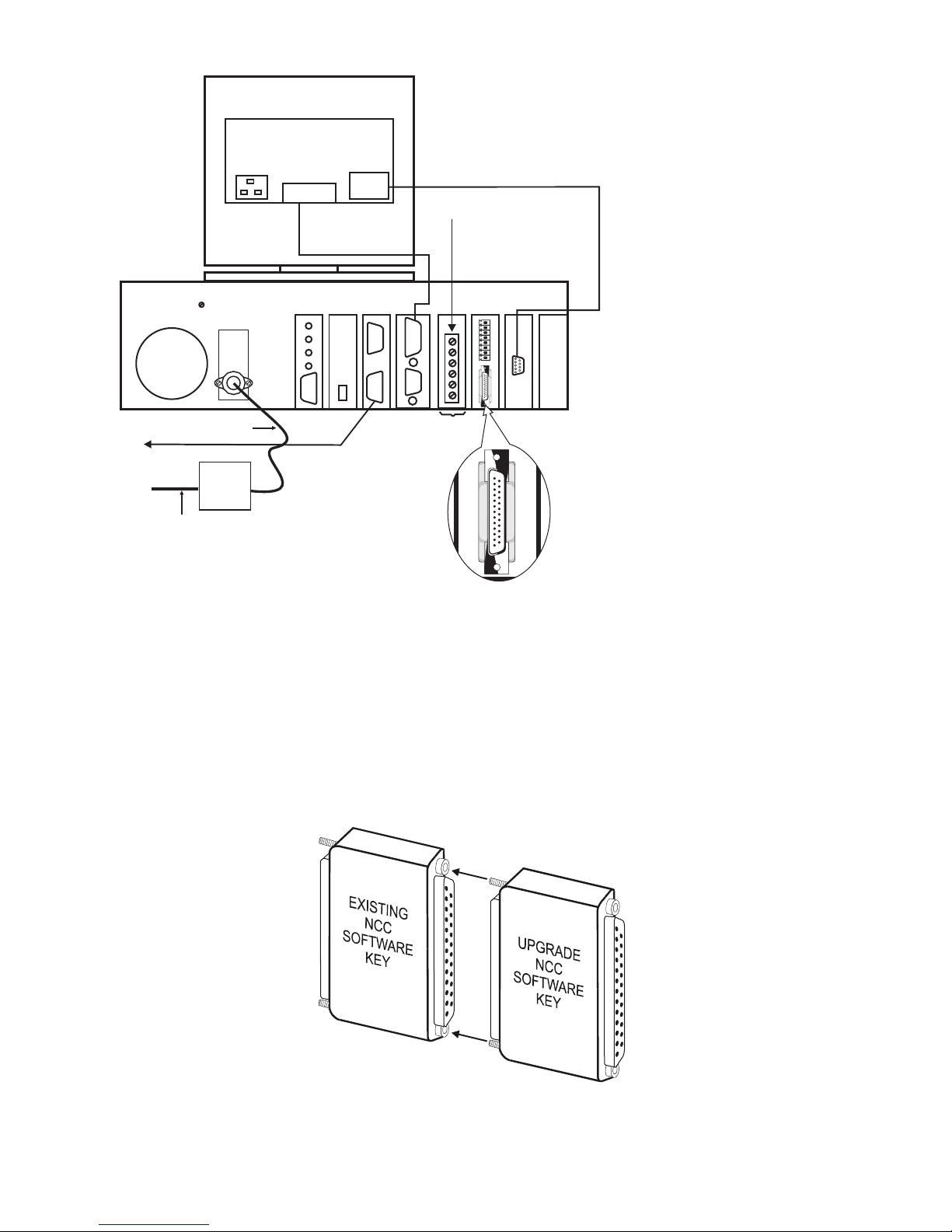
1.Your existing NCC computer should have the
original NCC software key plugged into the LPT
2 port as shown in Figure 1 on the next page.
2.Insert your NCC upgrade software key directly
into the existing NCC software key. Secure key
connection with screw terminals. See Figure 2
on the next page.
• NCC-4T-UK allows an existing NCC-4T (64
node/text) to upgrade to a NCC-4G (64 node/
graphics)
• NCC-GL1 allows an existing NCC-GL system to
upgrade to a NCC-1G (16 node/graphics)
Siemens Building Technologies, Inc.
8 Fernwood Road
Florham Park, New Jersey 07932
P/N 315-096334-2
3.Once the NCC upgrade software key is securely
attached to the original NCC software key, reboot
the computer.
Siemens Building Technologies, Ltd.
2 Kenview Boulevard
Brampton, Ontario L6T 5E4 CN
120 VAC
(NCC Key)
LPT PORT 2
60 Hz
Flexible Conduit
To Parallel Printer
See Notes 3 and 5
AC Main
120 VAC 60Hz
(User Supplied)
Junction
Box
(user
supplied)
Conduit
Figure 1
Original NCC Software Key Placement
Monitor
(rear view)
Touch
Port A
Interface
See Notes 3 and 4
Computer (rear view)
LPT1
Ethernet
Sound
Card
See Notes 1, 2, 3, 4, and 5
*The COM port on the Main
CPU must be disabled if
NCC-1F is being used.
See Note 13
VIDEO
Keyboard
SCD19TM or SCD21TM
6
5
4
Mouse
3
2
1
LPT PORT 2
COM 2
Elo TouchScreen
Controller Card
See Note 14
1
2
3
4
5
6
7
8
(NCC Key)
NOTES:
1. NCC-1F card is installed in a 16-bit ISA
slot and is set for COM2.
2. Connect the keyboard and mouse to the
computer's keyboard and mouse ports
following the computer's installation
instructions.
3. NFPA 72 Proprietary and Local System
installation requires that the computer,
monitor, and printer be UL rated for fire
(SIEMENS Models SCD550, SCD550T,
SCD19M, SCD19TM, SCD21M,
SDC21TM and PAL-1, respectively).
4. The computer is supervised for power
and connection to MXL.
5. The printer is supervised for AC, on/off
line, paper out, paper jam, and connection to the computer by NCCNT-G
software at the computer.
6. All circuits are power limited.
7. Cable must be in rigid conduit and cannot
leave the room.
8. Shielded cable is not recommended.
9. Power limited to NFPA 70 per NEC 760.
10.Maximum voltage: 24V peak to peak.
11.Maximum current: 20mA per circuit.
12.LPT2 has software key.
13.The COM Port on the Main CPU is
disabled. The Serial Port on the Serial
Parallel Adapter card takes on the
identification of COM1. The NCC-1F card
is identified as COM2.
14.If you are using model SCD-19M, the
touch screen controller card is not
installed.
15.Pin 1 & 2 of the LPT2 board can be wired
to a TRI module to monitor the status of
the computer's CPU.
Figure 2
Connecting The Upgrade NCC Software Key To The Existing NCC Software Key
2

4.To reboot the NCC computer, first press the Alt +
F4 keys simultaneously to close the NCC program.
The following window pops up:
Figure 3
NCCNT Command Center Close Window
Click the OK button. The same window pops up a
second time. Click on the OK button again.
As the NCC program is rebooting, the following
screen will display briefly:
In this window, you will see the statement: If you
do not want to restart the NCC, hit CTRL-C.
Press the Ctrl key and the C key simultaneously.
The following statement appears: Terminate
batch job (Y/N)? as shown in the following
window:
Figure 6
Terminate Batch Job (Y/N)? Screen
Choose Y and press ENTER.
From the Windows NT Start Button, click on
Shut Down. From the Shut Down menu, choose
the option to restart and press OK.
Figure 4
FireFinder Splash Screen
5.Immediately click the EXIT button to halt the NCC
start up process.
WINDOWS NT™
C:\WINNT\System32\CMD.exe appears in the toolbar
at the bottom of the computer screen. Click on this
filename to maximize to the following window:
The FireFinder Splash Screen appears (see
Figure 4). Click OK or ignore it to proceed.
OS/2
When the “STARTUP.CMD” window appears,
you may do any one of the following:
• Press CTRL+C to exit the startup loop
• Open a new command window from the launch
pad
• Shutdown the system
Select Shutdown on the LaunchPad.
Figure 5
C:\WINNT\System32\CMD.exe Screen
3

The following window appears:
Select OK. The following window appears:
Close any active programs that are still running by
clicking on the “Yes” button. (One window will pop
up for each active program.) When Shutdown
indicates it is now safe to restart your computer,
use the CTRL-ALT-DEL keys to reboot the system.
button on the main display, then hit the SETUP button.
From the system setup notebook, hit the DISPLAY
tab. You will see the enable graphics display option.
Click in the adjacent box so that a check mark ()
appears next to the option. This check mark assures
that the option has been activated. Once activated, hit
the SAVE button to save this option; then hit DONE to
get back to the main display.
Once the graphics feature is turned on, the other
graphic specific features are accessible. For instance,
by pressing the MORE-SETUP button sequence you
can now see graphic specific options highlighted (such
as the Images option).
Note: If the screen below appears after the NCC
program has been rebooted, you should double-check
the model number on the NCC Upgrade Key. The
appearance of this screen indicates that an NCC key
with less features than the original NCC system has
been attached.
The FireFinder Splash Screen appears (see
Figure 4). Click OK or ignore it to proceed.
6.Log On to the NCC. The extended operating
parameters will now be available. For example, if
you ordered the NCC-16T, your network menu will
now have an additional 16 node incremental tab.
You can access the network menu by pressing the
MORE-SETUP-NETWORK button sequence.
NCC-T-UK series
If you are installing any of the NCC-T-UK series, you
will need to enable the graphics display option. To
enable the graphics display option, hit the MORE
Figure 7
Security Key Values Changed Screen
If the NCC Key Model number is accurate, please
contact Siemens, Fire Safety Technical Support
Department at 1-800-248-7976.
Siemens Building Technologies, Inc.
8 Fernwood Road
Florham Park, New Jersey 07932
P/N 315-096334-2
Siemens Building Technologies, Ltd.
2 Kenview Boulevard
Brampton, Ontario L6T 5E4 CN
 Loading...