

Page 1
GAMMA instabus
Technical product information
July 2008
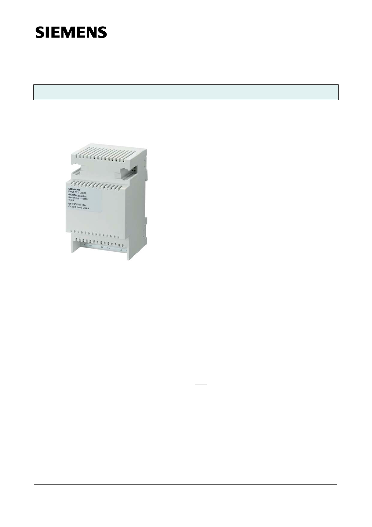
Switching actuator, submodule N 512/21 5WG1 512-1AB21
3x AC 230/400V, 16A, C-load, load-check
Product and functional description
output individually which switching state it is to assume
on a bus voltage failure and after the bus voltage recovery: as before bus voltage failure, ON or OFF.
Application program
The N 512/11 switching actuator needs the application
program "07B0 A15 Switching Actuator 981B01". This
controls the outputs of the main module as well as the
outputs of all connected submodules via their 6-pole
interface.
In bus mode, a communication object can be available
for each actuator output - for switching, for manual
override, for a forced control, for a logical combination
and for status query. Furthermore, if required, timelimited switching instead of permanent switching on can
be enabled for each channel via an optional "Night
mode" object (e.g. for lighting while cleaning), if need be
with a warning before switching off by multiple switching the output on and off (flashing). It can also be selected whether all a module's outputs are to be set jointly
The switching actuator submodule N 512/21 is a 3 MU
(module units) wide device for DIN-rail mounting in Nsystem dimensions, with 3 switching outputs (relay contacts) for AC 230/400V, 16A, C-load, each with load current measurement and monitoring (load-check). A submodule cannot be operated stand-alone or be directly
connected to the bus. But it can be connected via a special 6-pole bridging connector either with a switching
actuator main module or with another submodule which
is already connected to a main module (see figure 1).
The submodule electronics are supplied by bus voltage
via the 6-pole bridging connector.
In total up to 4 switching actuator submodules can be
connected in series to a switching actuator main module,
so that a main module, if need be, can be extended simply from a 3-fold to a 6-, 9-, 12- or 15-fold switching
actuator and thus be matched flexibly to the number of
loads to be switched.
It is indicated by flashing of the corresponding green LED
A to E on the top of the main module if more submodules are set than are actually connected or if the set
submodule type does not correspond with the submodule type actually connected or if a submodule is
detected as faulty.
and thus identically or whether each output is to be set
separately and individually.
Amongst others, the application program includes optional detection and monitoring of the load current for
each output on load failure and/or overload, simultaneous switching of all 3 outputs (3-phase switching), conversion of a speed given as a percentage value into 1- to
3-stage switching commands (fan speed control), conversion of a valve setting given as a percentage value
into a pulse width modulated (PWM) switching command (thermal drive control), a switching cycle and
operating hours count with threshold monitoring for
each output and an integrated 8-bit scene control, in
which each output can be incorporated into up to 8 scenes.
To load the application program, the Engineering Tool
Software (ETS) is required as version 3.0 f or higher.
: If the N 512/11 application program is "unloaded"
Note
with the ETS, then you will no longer be able to activate
direct mode, i.e. the LED status display and local switching of the outputs using the buttons on the front panel
of the actuator are disabled. Only after reloading the
application program can you re-enable the status display
and direct mode.
Behavior in case of mains failure / recovery
Because the electronics of a submodule are fed from the
bus (via the 6-pole interface to the main module), a
mains failure then leads solely to a failure of the submodule if the bus voltage also fails as the result of a
mains failure. However, it can be set for each submodule
Siemens AG N 512/21, 4 pages Technical manual
Industry Sector, Building Technologies
Electrical Installation Technology © Siemens AG 2008 Update: http://www.siemens.com/gamma
P.O. Box 10 09 53, D-93009 Regensburg Subject to change without further notice
2.4.3.3/1
Page 2
GAMMA instabus
Technical product information
July 2008
Switching actuator, submodule N 512/21 5WG1 512-1AB21
3x AC 230/400V, 16A, C-load, load-check
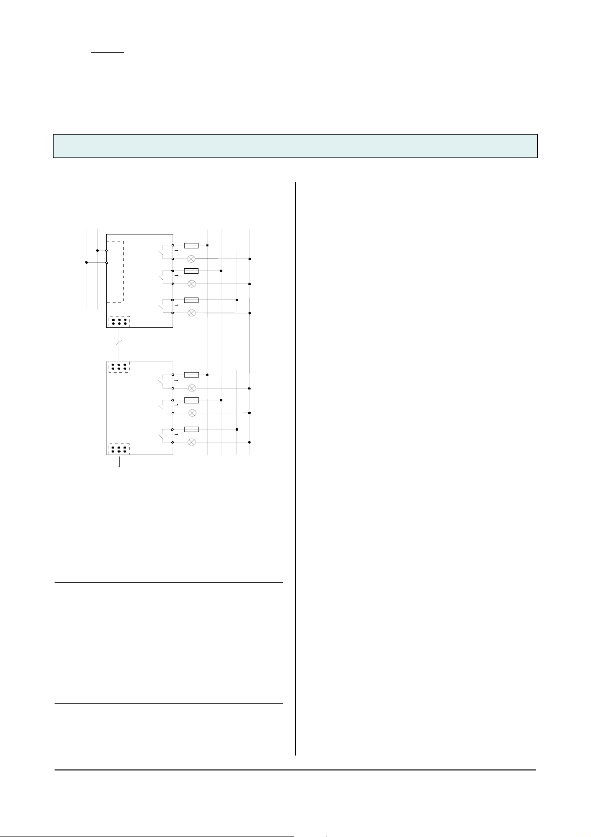
Connection example
Schaltaktor, Hauptmodul
Switching actuator, main module
N 512/11
Ausgang 1
Output 1
t
i
n
u
r
e
g
l
n
p
i
X
l
p
p
Ausgang 2
N
o
u
k
K
o
Output 2
n
c
a
s
s
u
u
B
B
Ausgang 3
Output 3
L1
1
L2
2
L3
3
L3
N
L2
L1
A
6
Schaltaktor, Erweit erung
Switching actuator, submodule
N 512/21
Ausgang 1
Output 1
Ausgang 2
Output 2
Ausgang 3
Output 3
L1
1
L2
2
L3
3
B
C ... E
Figure 1. Connection example
Installation notes
• The device can be used for permanent installation in
dry interior rooms and for insertion in distribution
boards or miniature housings.
V
DANGER
• The device must be mounted and commissioned by an
authorised electrician.
• When connecting the device, it should be ensured that
the device can be isolated.
• The device must not be opened.
• For planning and construction of electric installations,
the relevant guidelines, regulations and standards of
the respective country are to be considered.
• With the last submodule no bridging connector must
be plugged into the jack for a further submodule on
the right submodule side.
Technical data
Power supply
• Bus voltage: via the 6-pole bridging connector
• Bus current per submodule: typically 1 mA
• Power dissipation: if all outputs = OFF: 0.03 W,
at max. load and all outputs = ON: approx. 3.5 W
Outputs
• 3 switching outputs, potential-free relay contacts:
- rated voltage: AC 230/400 V, 50/60 Hz
- rated current: 16 AX (200 µF) to DIN EN 60669-1,
16 A in AC1 mode (cos ϕ = 0.8) and in AC3 mode
(cos ϕ = 0.45) as to DIN EN 60947-4-1,
- DC switching capacity: 16A at 24V DC
- Min. switching capacity: 100 mA at 12V AC
- Incandescent lamp load: max. 3,680 W
- LV halogen lamps, inductive transformer: 2,000 W
- LV halogen lamps, electronic transformer: 2,500 W
- Number of OSRAM ballasts for T5/T8:
QTI 1x28/54W: 56, QTP 1x36W: 31,
QT-M 1x26-42W:21, QTP 2x58W: 9,
QT-FQ 1x80W: 9
- Mech. lifetime: > 1,000,000 switching cycles
- Electr. lifetime: > 100,000 at AC1, > 30,000 at AC3
- Load current measuring range: 0.1...20 A, sinusoidal
- Load current frequency range: 50/60 Hz, +/- 5 Hz,
- Measuring accuracy: +/- 9 % of the current measured
value and +/- 130 mA,
- Max. relay position changes per output and evenly
distributed per minute with simultaneous switching of
all relays: 20 with 3 outputs, 10 with 6 outputs, 7 with
9 outputs, 5 with 12 outputs, 4 with 15 outputs
Operating elements
• none
Display elements
• none
Connections
• Output circuits: screw-type terminals,
insulation strip length 7... 9 mm.
The following conductor cross-sections are permitted:
- 0.5... 4.0 mm² single-core,
- 0.5... 2.5 mm² finely stranded without / with connec-
tor sleeve.
• Each L-conductor connection to the N 512/11 must be
fused with a circuit-breaker of characteristic B or C for
a max. nominal current of 16 A!
• Submodule: 6-pole jack for bridging connector.
Technical manual N 512/21, 4 pages Siemens AG
Industry Sector, Building Technologies
Update: http://www.siemens.com/gamma © Siemens AG 2008 Electrical Installation Technology
Subject to change without further notice P.O. Box 10 09 53, D-93009 Regensburg
2.4.3.3/2
Page 3

GAMMA instabus
Technical product information
July 2008
Switching actuator, submodule N 512/21 5WG1 512-1AB21
3x AC 230/400V, 16A, C-load, load-check
Mechanical data
• Housing: plastic
• Dimensions: DIN rail mounted device in N dimensions,
width 3 module units (1 module unit = 18 mm)
• Weight: approx. 225 g (inclusive of bridging connec-
tor)
• Fire load: approx. 2800 kJ
• Installation: Snap-on mounting on DIN rail
EN 60715-TH35-7.50
Electrical safety
• Degree of pollution (according to IEC 60664-1): 2
• Type of protection (according to EN 60529): IP 20
• Overvoltage category (according to IEC 60664-1): III
• Device complies with: EN 50090-2-2 and EN 60669-2-1
EMC requirements
• Complies with EN 50090-2-2, EN 50428 and
EN 60669-2-1
Environmental conditions
• Climatic withstand capability: EN 50090-2-2
• Ambient operating temperature: - 5 ... + 45 °C
• Storage temperature: - 25 ... + 70 °C
• Relative humidity (not condensing): 5 % to 93 %
Markings
• none (no device with bus interface)
CE mark
• In accordance with the EMC guideline (residential and
functional buildings), low voltage guideline
Location and function of connectors
A1
A2
A3
Figure 2. Connectors
A1 Jack for connection of a switching actuator sub-
module to a switching actuator main module or to a
preceding submodule
A2 Jack for connection of a further switching actuator
submodule
A3 Screw-type terminals of outputs 1...3
Installation and wiring
Mounting / dismounting the device
see figure 3 and 4
B2
:
B1
Figure 3. Mounting the device
Siemens AG N 512/21, 4 pages Technical manual
Industry Sector, Building Technologies
Electrical Installation Technology © Siemens AG 2008 Update: http://www.siemens.com/gamma
P.O. Box 10 09 53, D-93009 Regensburg Subject to change without further notice
2.4.3.3/3
Page 4

GAMMA instabus
Technical product information
July 2008
Switching actuator, submodule N 512/21 5WG1 512-1AB21
3x AC 230/400V, 16A, C-load, load-check
C2
C1
Figure 4. Dismounting the device
C3
Connecting a switching actuator submodule: see figure 5
Snap the switching actuator submodule on to the rail
and push it to the left against the switching actuator
main module or against the switching actuator submodule. Connect both devices using the bridging connector supplied.
Space for notices
AB C
Figure 5. Connecting a switching actuator submodule
General notes
• Any faulty devices should be returned to the local
Siemens office.
• If you have further questions about the product,
please contact our Technical Support:
℡ +49 (0) 180 50 50-222
" +49 (0) 180 50 50-223
! www.siemens.com/automation/support-request
Technical manual N 512/21, 4 pages Siemens AG
Industry Sector, Building Technologies
Update: http://www.siemens.com/gamma © Siemens AG 2008 Electrical Installation Technology
Subject to change without further notice P.O. Box 10 09 53, D-93009 Regensburg
2.4.3.3/4
 Loading...