

Page 1
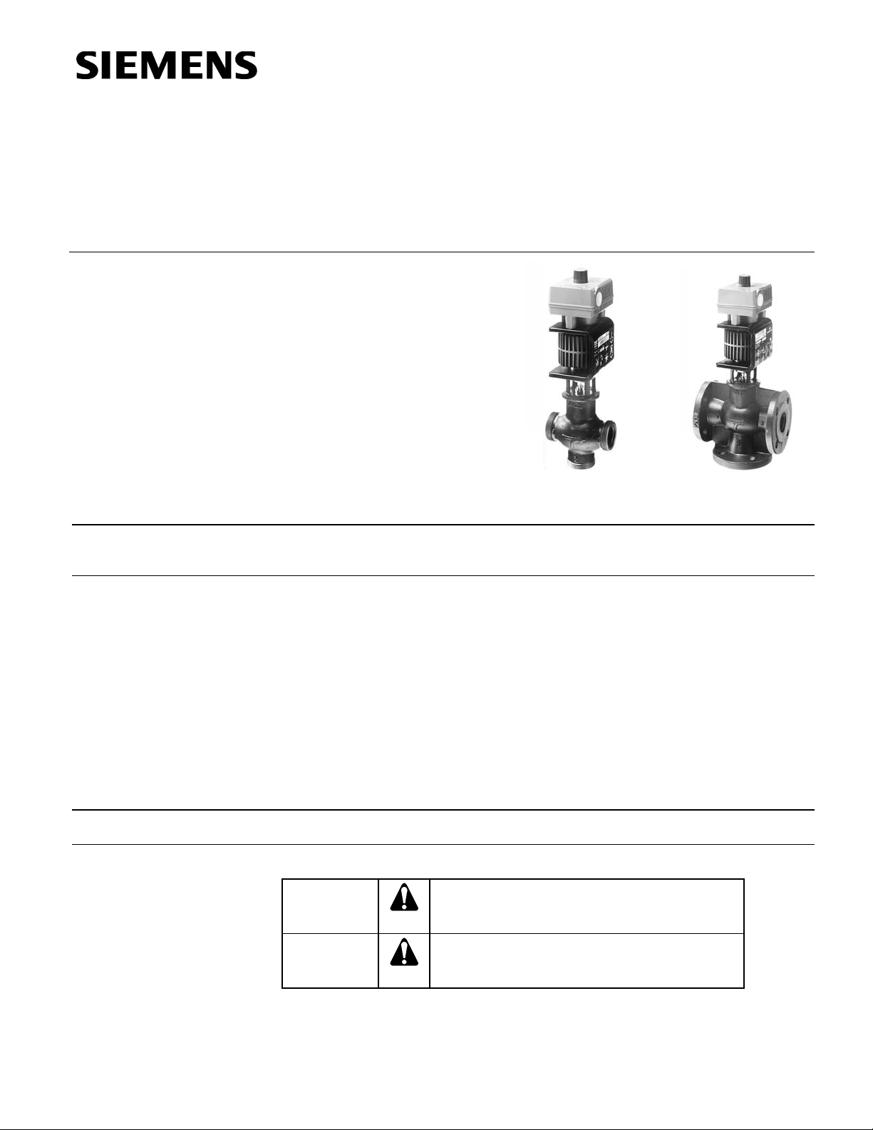
MXG461…U,
MXF461…U Series
Modulating Control Valves with
Magnetic Actuators
Technical Instructions
Document No. CA1N4455E-P25
May 8, 2009
Description
Features
Product Numbers
Mixing or straight-through valves with magnetic actuators for modulating control of hot
and chilled water systems in closed circuits.
• Fast positioning time (< two seconds), high-resolution stroke (1:1000).
• Linear or equal-percentage valve characteristic (user-selected).
• Switch-selectable control signal: 0 to 10 Vdc, 2 to 10 Vdc, or 4 to 20 mA.
• Wear-free inductive stroke measurement.
• Low friction, robust, no maintenance required.
• Fail-safe feature: A → AB closed when de-energized.
• Positioning control.
• Position feedback.
• Manual control.
See Table 1.
Warning/Caution Notations
Sval0016R1
MXG461…U MXF461…U
Sval0015R1
WARNING:
CAUTION:
Personal injury or loss of life may occur if you do not
follow the procedures as specified.
Equipment damage or loss of data may occur if you
do not follow the procedures as specified.
Siemens Building Technologies, Inc.
Page 2
Technical Instructions MXG461…U, MXF461…U Modulating Control Valves
Document Number CA1N4455E-P25 with Magnetic Actuators
May 8, 2009
Application
Ordering
Principles/
Construction
Automatic Control
The MXG461...U (screwed fitting) and MXF461...U (flange fitting) valves are mixing or
straight-through valves with a factory calibrated and mounted magnetic actuator. The
magnetic actuator incorporates an electronics module for position control and
positioning feedback. Control path A → AB is closed when the valve is de-energized.
CAUTION:
The valve is suitable for straight-through normally closed or three-way
applications and may be installed only in a mixing arrangement.
The direction of flow (A → AB) must be as indicated on the valve.
The fast positioning time, high resolution and high rangeability make these valves ideal
for modulating control of chilled and hot water systems in closed circuits. Sturdy
construction makes maintenance and regular servicing unnecessary and ensures a
long service life.
When using a 2-1/2 inch flanged valve in a straight-through application, a blanking
flange is required for the third port. If required, order Z155/65 separately.
For screwed valves, no additional ordering is required. The components required to
create a straight-through valve are included with the valve.
The control signal is converted by the microprocessor in the electronics module into an
output signal that generates a magnetic field in the core. This causes the only moving
part, the armature, to change its position in accordance with the interacting forces
(magnetic field, counter-spring, hydraulics, and so on). The armature responds rapidly
to any change in signal, transferring the corresponding movement directly to the control
disc, enabling fast changes in load to be corrected quickly and accurately. The valve
position is measured continuously. The positioning controller ensures an exactly
proportional relationship between the control signal and the valve stroke.
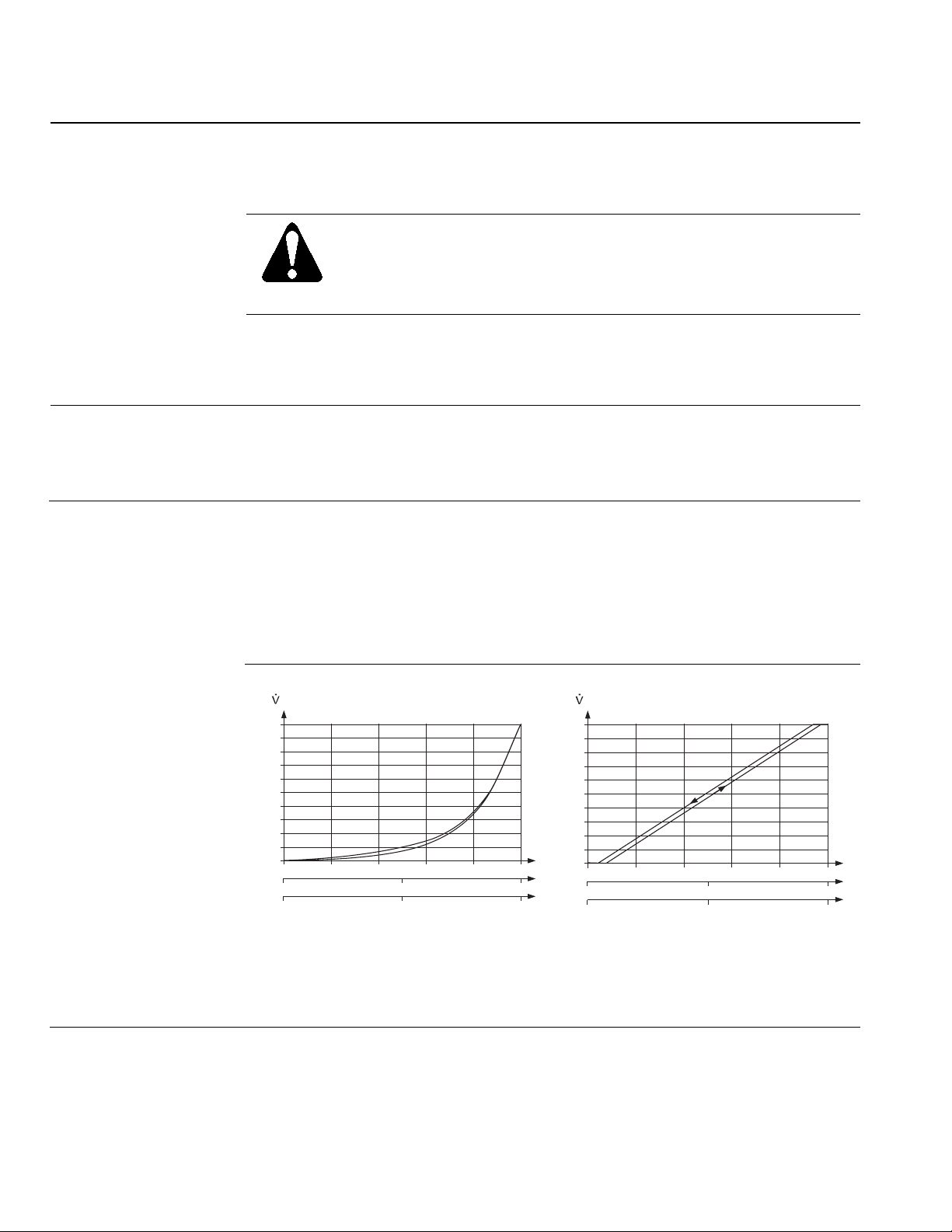
Valve Characteristic
Volumetric flow
[%]
100
80
60
40
20
0
2
4
SVAL0227R1
86420
6
12
Control signal
Volumetric flow
100
80
60
40
20
y
10 [V]
y
10 [V]
y
20 [mA]
Sval0012R2
[%]
0
2
4
6
12
86420
10 [V]
10 [V]
20 [mA]
Control signal
Figure 1. Equal-percentage. Figure 2. Linear.
In the event of a power failure, or if the power is switched off, the spring force closes the
valve automatically (control path ports A → AB normally closed).
y
y
y
Page 2 Siemens Building Technologies, Inc.
Page 3
MXG461…U, MXF461…U Modulating Control Valves Technical Instructions
1
1
1
With Magnetic Actuators Document Number CA1N4455E-P25
May 8, 2009
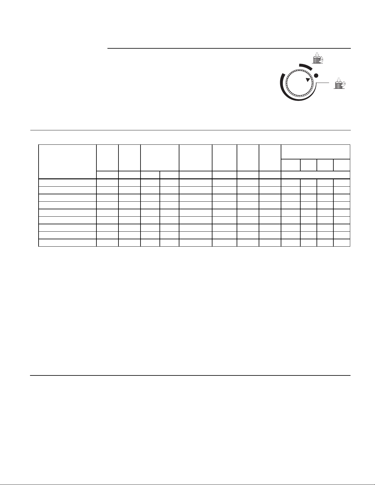
Manual Control
The valve control path (ports A → AB) can be opened
mechanically up to 95% of the full stroke by pressing the
handwheel inward and turning it clockwise (to the
MANUAL position). This disables the control signal from
the controller.
To disable automatic control of the valve, press the
handwheel inward and turn it counterclockwise (to the
OFF position). The valve will close.
For automatic control, the handwheel must be set to the
OFF
AUTO
MANUAL
Sval0006R1
Figure 3. Selecting
Automatic Control.
AUTO position (the handwheel will spring out).
Sizing
Table 1. MX.461…U - Valves Sizing.
Maximum Wire Gauge
Line
Product Numbers
Size
Close-off
C
Δ P
V
max
Pressure
S
NA
P
med
I
N
18 16 14 12
(in) (gpm) (psi) (bar) (psi) (VA) (W) (A) Cable Length L (ft)
MXG461.15-0.6U 1/2 0.7 44 3 44 29 5 3.15 108 213 361 525
MXG461.15-1.5U 1/2 1.7 44 3 44 29 5 3.15 108 213 361 525
MXG461.15-3.0U 1/2 3.5 44 3 44 29 5 3.15 108 213 361 525
MXG461.20-5.0U 3/4 5.8 44 3 44 29 5 3.15 108 213 361 525
MXG461.25-8.0U 1 9.3 44 3 44 29 5 3.15 108 213 361 525
MXG461.32-12U 1-1/4 14.0 44 3 44 29 5 3.15 108 213 361 525
MXG461.40-20U 1-1/2 23.0 44 3 44 44 6 4.00 66 118 197 328
MXG461.50-30U 2 35.0 44 3 44 44 6 4.00 66 118 197 328
MXF461.65-50U 2-1/2 58.0 44 3 44 46 6 5.00 49 98 164 262
Key:
ΔPmax = Maximum permissible differential pressure across the valve’s control path,
valid for the entire actuating range of the motorized valve.
S
NA = Nominal apparent power for selecting transformer
P
med = Typical power consumption
N = Required slow fuse
I
C
= Flow rate to IEC534-2-4
V
Control path A → AB (normally closed): Tolerance ±5%
Control path B → AB (normally open): Tolerance ±10%
L = Maximum cable length. With four-wire connections, the maximum
permissible length of the separate 16 AWG Cu (copper) signal cable is
656 feet. With three-wire connections, the maximum permissible cable
length is reduced to 1/3 of the values shown in the table.
1 = All data relates to a 24 Vac supply.
Siemens Building Technologies, Inc. Page 3
Page 4
Technical Instructions MXG461…U, MXF461…U Modulating Control Valves
Document Number CA1N4455E-P25 with Magnetic Actuators
May 8, 2009
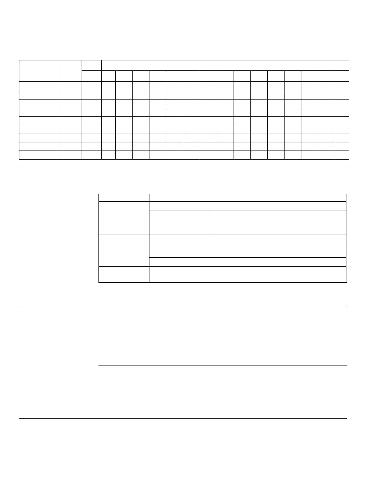
Table 2. Water Flow Chart.
Product
Number
MXG461.15-0.6U 1/2 0.7 0.7 1 1.2 1.4 1.6 1.7 1.9 2.0 2.1 2.2 2.7 3.1 3.8 4.4 4.9
MXG461.15-1.5U 1/2 1.7 1.7 2.4 2.9 3.4 3.8 4.2 4.5 4.8 5.1 5.4 6.6 7.6 9.3 10.8 12
MXG461.15-30U 1/2 3.5 3.5 4.9 6.1 7 7.8 8.6 9.3 9.9 10.5 11 14 16 19 22 25
MXG461.20-50U 3/4 5.8 5.8 8.2 10 12 13 14 15 16 17 18 22 26 32 37 —
MXG461.25-8.0U 1 9.3 9.3 13 16 19 21 23 25 26 28 29 36 42 51 59 —
MXG461.32-12U 1-1/4 14 14 20 24 28 31 34 37 40 42 44 54 63 77 89 —
MXG461.40-20U 1-1/2 23 23 33 40 46 51 56 61 65 69 73 89 103 126 145 —
MXG461.50-30U 2 35 35 49 61 70 78 86 93 99 105 111 136 157 192 221 —
MXF461.65-50U 2-1/2 58 58 82 100 116 130 142 153 164 174 183 225 259 318 367 —
Line
Size
(in)
ΔP
V100
CVS 1 2 3 4 5 6 7 8 9 10 15 20 30 40 50
PSI
LED Indicators
The two-color LED display indicating operating status can be viewed by opening the
cover of the electronics module.
Table 3. LED Display.
LED Display Status Description
LED green On continuously Automatic mode: Auto (normal, no faults)
Flashing – Mechanically set to MANUAL
– Mechanically set to OFF
– Currently in auto-calibration mode
LED red On continuously – General fault
– General calibration fault
– Microcontroller fault
Flashing – Faulty 24 Vac supply (that is, too low)
LED Off – No 24 Vac supply
– Fault with electronics module
As a general rule, the LED can only assume the conditions in Table 3 (continuously red
or green, flashing red or green, or off).
Mounting
Mounting and operating instructions are printed on the actuator and on the electronics
module.
The valve is suitable only for straight-through or three-way applications and may be
installed only in a mixing arrangement. In the case of the straight-through valve, strict
observance of the direction of flow is essential.
Do not mount with actuator below horizontal position.
Access for Mounting
It is essential to maintain the specified minimum clearance above and to the side of the
actuator and/or electronics module for servicing, installing and heat dissipation:
• 1/2-inch to 1-1/4 inches = 4 inches
• 1-1/2 inches to 2-1/2 inches = 6 inches
Also see Dimensions.
Page 4 Siemens Building Technologies, Inc.
Page 5
MXG461…U, MXF461…U Modulating Control Valves Technical Instructions
With Magnetic Actuators Document Number CA1N4455E-P25
May 8, 2009
Mounting,
Continued
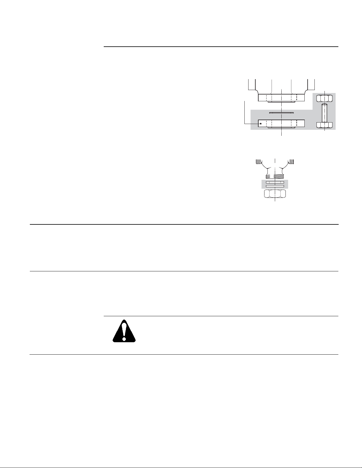
Only three-way MX.461...U valves are supplied. They may be used as straight-through
normally closed valves by closing off port "B":
Straight-through Valves
Port "B" can be sealed with a Z155/65
blanking flange and gasket.
Port "B" can be sealed with the
accessories supplied (blanking disk,
gasket, and the nut).
B
BLANKING
FLANGE
SVAL0008R1
Figure 4. MXF461...U Flanged Valves in
Straight-through Applications.
B
Sval0007R1
Figure 5. MXG461...U Screwed Valves in
Straight-through Applications.
Installation
Maintenance
MXG461...U screwed valves are flat-faced to facilitate sealing with the gaskets
supplied.
Do not use hemp, tape or thread-sealing compound.
Do not insulate the actuator.
For notes on electrical installation, see Terminal Layout.
The valves and actuators require no maintenance or service. The valve stem is sealed
with a maintenance-free O-ring gland.
Should the valve electronics prove faulty, the electronics module should be exchanged
for a replacement part, part number ASE1 (1/2-inch to 1-1/4 inches) or ASE2
(1-1/2 inches to 2-1/2 inches). Mounting instructions are enclosed (Ref. 35678).
WARNING:
Under operating conditions within the limits defined by the application
data, the actuator will become hot, but this does not represent a fire risk.
Always maintain the minimum clearance specified (see Dimensions).
Siemens Building Technologies, Inc. Page 5
Page 6

Technical Instructions MXG461…U, MXF461…U Modulating Control Valves
Document Number CA1N4455E-P25 with Magnetic Actuators
May 8, 2009
Specifications
Electrical Interface
Power supply Class 2
Supply voltage 24 Vac, 50/60 Hz
– Maximum voltage tolerance +20/–15%
Control signal (user-selected) 0 to 10 Vdc, 2 to 10 Vdc, or 4 to 20 mA
Software class Class A
Nominal power See Sizing
Position Signal Y 0 to 10 Vdc, 2 to 10 Vdc, or 4 to 20 mA
Impedance 0 to 10 Vdc or 2 to 10 Vdc 100k Ω //5nF
4 to 20 mA 100 Ω //5nF
Position feedback signal 0 to 10 Vdc; load resistance > 500 Ω
Product Specific Data Applications To EN60730
Nominal pressure 232 psi (16 bar)
Permissible Operating pressure p
Differential pressure ΔP
Leakage at ΔP
v = 14.5 psi (0.1 Mpa) (1bar) A → AB Max. 0.02 % Cv (to IEC534-4)
max See Table 1
max 150 psi
e
B → AB Depends on operating
conditions (<0.2% C
v)
Admissible media Water, or water/glycol mixtures with
maximum 50% glycol
Temperature of medium 34°F to 266°F (1°C to 130°C)
Valve characteristic (stroke, k
vs) Linear or equal percentage (user-
selected), optimized near the closing
point (to IEC534-2-4)
Stroke resolution ΔH/H
100 1:1000 (H = stroke)
Hysteresis Typically 3%
Type of operation Modulating
Manual adjustment Yes, with handwheel
Position with actuator de-energized A → AB closed
Orientation Upright to horizontal
Note that orientation affects protection
standard
Positioning time <2 seconds
Materials (valve body) Housing parts Cast iron
Plug CrNi Steel
Seat Brass
Valve stem seal EPDM (O-ring)
Bellows Tombac, bronze, CrNi steel
Electrical connection Connection terminal Screw terminals
Per terminal, with wire (no lug) 2 × 16 AWG or 1 × 14 AWG
Per terminal with wire 2 × 16 AWG or 1 × 12 AWG
Miscellaneous Weight (including packaging) See Dimensions
Dimensions See Dimensions
Ambient conditions Maximum ambient temperature 113°F (45°C)
Agency Approvals UL listing Per UL 873
C-UL Certified to Canadian Standard
C22.2 No. 24
Suitable for use in air handling spaces
NEMA Type 1
Page 6 Siemens Building Technologies, Inc.
Page 7
MXG461…U, MXF461…U Modulating Control Valves Technical Instructions
With Magnetic Actuators Document Number CA1N4455E-P25
May 8, 2009
Wiring Terminals
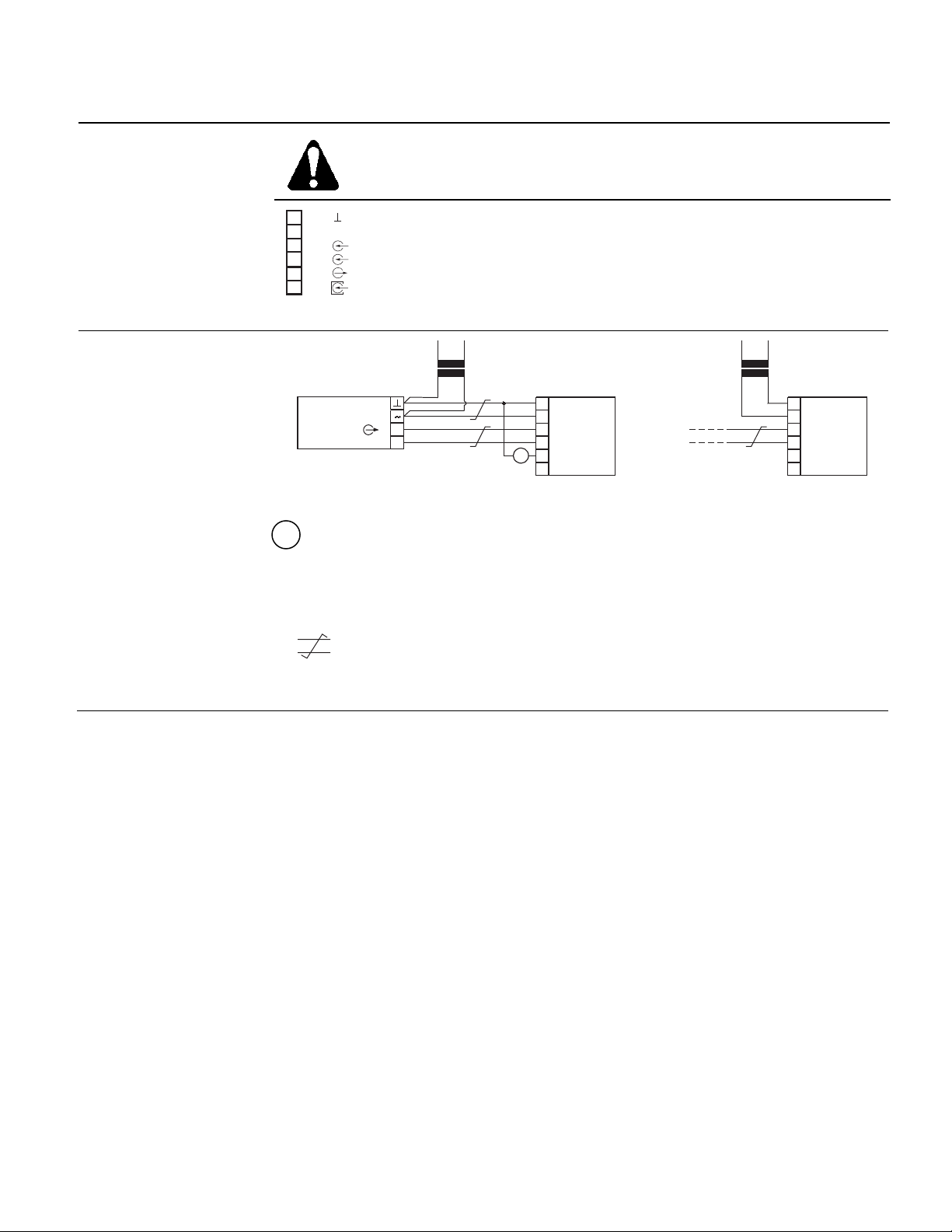
WARNING:
Earth ground must be connected to the pipe work.
1
2
3
4
5
6
Sval0011R1
G0
G
Y
YM
X
YF
24 Vac
~
24 Vac
Control signal input
Control signal reference voltage
0 to 10 Vdc stroke signal output (position feedback)
Override control
Figure 6. Terminal Layout for Four-wire Connections.
Wiring Diagram
24
VAC
1
2
3
4
5
6
MX...461...
G0
G
Y
YM
X
YF
0-10 VDC
2-10 VDC
4-20 mA
Sval00228R1
24 VAC
24
VAC
+
±
U
1
2
3
4
5
6
MX...461...
G0
G
Y
YM
X
YF
Figure 7. Connection to Controller with Four-wire Output.
U = Indication of valve position (only where required). 0 to 10 Vdc → 0 to 100%
volumetric flow
SSEN0093R1
TWISTED PAIRS
If the cables for the 24 Vac supply and the control signal 0 to 10 Vdc
(2 to 10 Vdc, 4 to 20 mA are routed separately, twisted pairs are not required for the
24 Vac cable).
Siemens Building Technologies, Inc. Page 7
Page 8
Technical Instructions MXG461…U, MXF461…U Modulating Control Valves
Document Number CA1N4455E-P25 with Magnetic Actuators
May 8, 2009
Forced Control Feature
(Input Terminal YF/6)
0 Vac (Bridge G0 – YF)
24 Vac (Bridge G – YF)
1 to 9 Vdc at F
Control path A → AB closed
Control path A → AB open
Continuously variable low limit control 10% to 90% volume
flow (the higher value YF of Y takes priority).
This function is available with valves with a manufacturing
date of 990701 or later.
Configuration
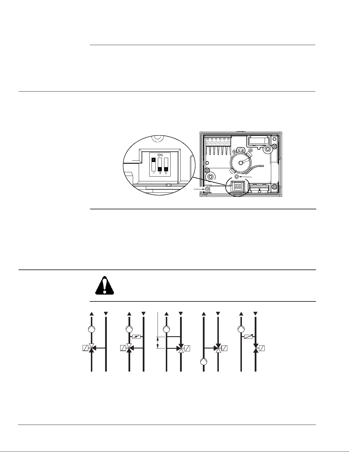
Switches
Switch
1 Characteristic
2 Control signal
3 Volts or mA
Off
Linear
0 to 10 Vdc*
0(2) to 10 Vdc*
On
Equal percentage*
2 to 10 Vdc or 4 to 20 mA
4 to 20 mA
* Factory setting: equal percentage valve characteristic, 0 to 10 Vdc control signal.
70038c
A
B
Calibration
Figure 8. DIP Switches.
The MX…461…P magnetic valves are factory-calibrated at 0% and 100% stroke. When
commissioning the valves (especially under extreme usage conditions) there may still
be some leakage via control path A → AB with a 0% stroke control signal (0 Vdc, 4 mA
or 2 Vdc). In this case, the valve can be recalibrated as follows (see Figure 8):
• Use a pin or paper clip to push the button in opening (A) in the terminal housing.
• During calibration, the LED light (B) in the electronics module will flash green for
approximately 10 seconds. The valve will be briefly closed and fully opened.
Application Example
CAUTION:
This valve is suitable for straight-through normally closed or three-way
applications only, and should only be installed in a mixing arrangement.
(min. 20 in)
Sval0014R1
AB
C
A
B
AB
B
A
A
A
AB
x D N
B
B
10
A
B
AB
D E
A
AB
A Mixing circuit
B Mixing circuit with bypass (underfloor heating)
C Injection circuit
D Diverting circuit
E Injection circuit with straight-through valve
Page 8 Siemens Building Technologies, Inc.
Figure 9. Hydraulic Circuits.
Page 9
MXG461…U, MXF461…U Modulating Control Valves Technical Instructions
With Magnetic Actuators Document Number CA1N4455E-P25
May 8, 2009
Service
CAUTION:
Do not disassemble the valve and actuator combination. This assembly is factorycalibrated, and should only be replaced by qualified personnel.
Dimensions
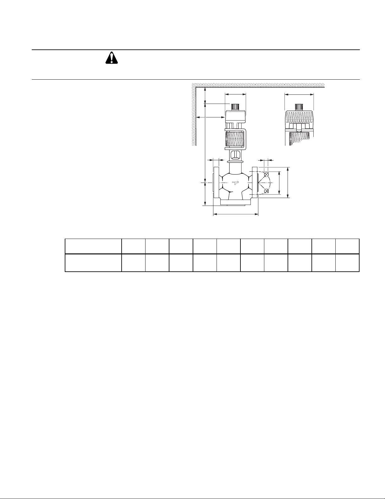
All dimensions in inches (millimeters)
Sval0009.eps
min.
H
1
L
100
min.
100
b
E
ø d
A B
A
B
L
ø k
F
ø D
Table 4. MXF461…U – Flanged Valve with Electronics Module.
Product Number L L1 D b k d H E F lbs
4X
MXF461.65-50U
11.42
(290)
4.92
(125)
7.00
(177.8)
0.88
(22.4)
5.50
(139.7)
0.75
(19.05)
15.43
(392)
3.15
(80)
3.94
(100)
(kg)
63.1
(28.6)
NOTE: Installer must supply counterflanges. lbs. (kg) = Weight (including packaging)
Siemens Building Technologies, Inc. Page 9
Page 10
Technical Instructions MXG461…U, MXF461…U Modulating Control Valves
Document Number CA1N4455E-P25 with Magnetic Actuators
May 8, 2009
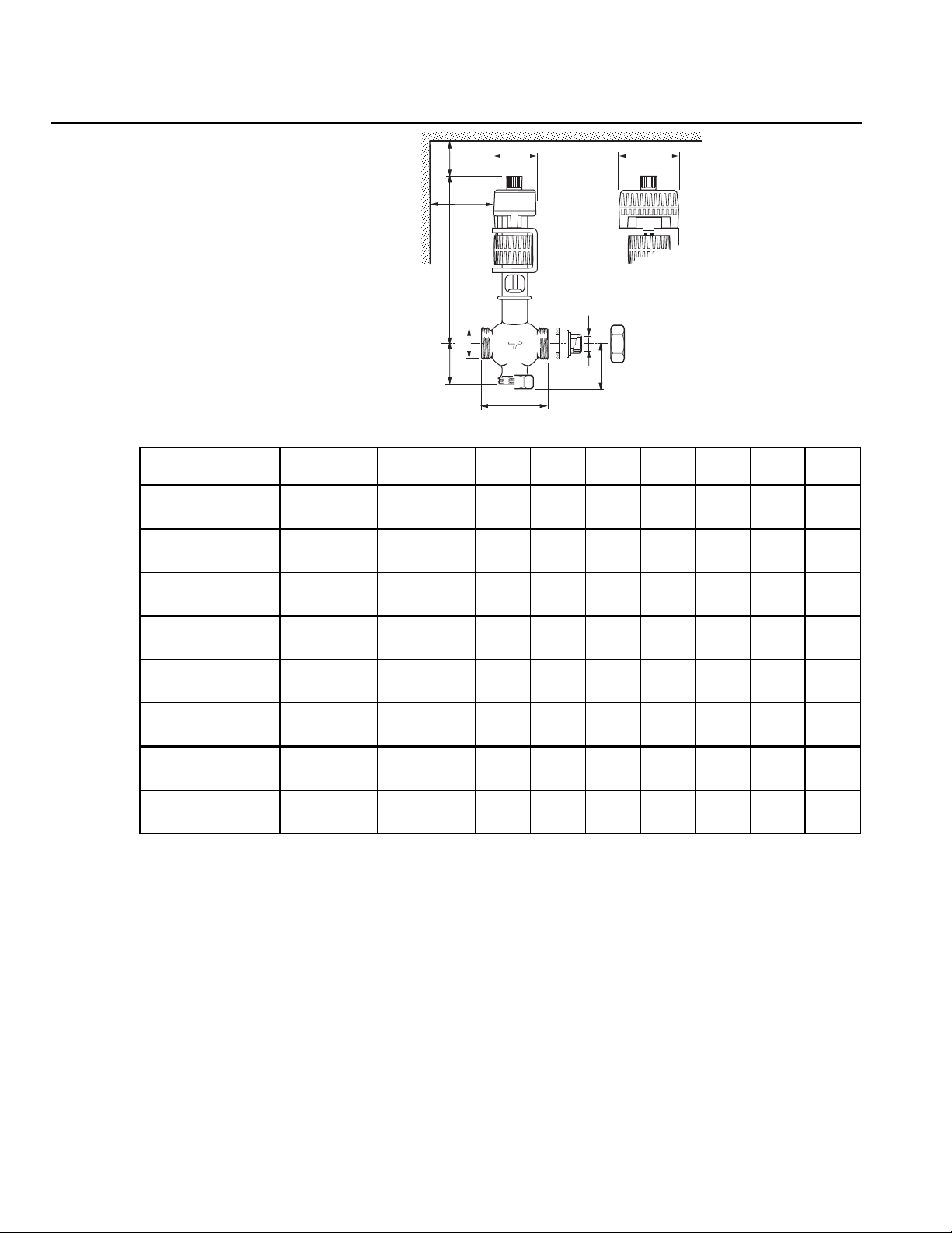
Dimensions,
Continued
All dimensions in inches
(millimeters)
Sval0010R1
1
L
min.
H
100
min.
100
DA
E
DI
AB
A
B
L
2
L
60433
F
Table 5. MXG461…U –Valves with Electronics Module.
Product Number DI DA L L1 L2 * H E F lbs
MXG461.15-0.6U 1/2 1
MXG461.15-1.5U 1/2 1
MXG461.15-3.0U 1/2 1
MXG461.20-5.0U 3/4 1-1/4
MXG461.25-8.0U 1 1-1/2
(110)
MXG461.32-12U 1-1/4 2
(125)
MXG461.40-20U 1-1/2 2-1/4
(140)
MXG461.50-30U 2 2-3/4
(170)
3.15
(80)
3.15
(80)
3.15
(80)
3.74
(95)
4.33
4.92
5.51
6.69
1.67
(42.5)
1.67
(42.5)
1.67
(42.5)
2.07
(52.5)
2.22
(56.5)
2.66
(67.5)
3.17
(80.5)
3.68
(93.5)
2.01
(51)
2.01
(51)
2.01
(51)
2.40
(61)
2.56
(65)
2.99
(76)
3.70
(94)
4.29
(109)
9.45
(240)
9.45
(240)
9.45
(240)
10.24
(260)
10.63
(270)
11.22
(285)
12.60
(320)
13.39
(340)
3.15
(80)
3.15
(80)
3.15
(80)
3.15
(80)
3.15
(80)
3.15
(80)
3.94
(100)
3.94
(100)
3.94
(100)
3.94
(100)
3.94
(100)
3.94
(100)
3.94
(100)
3.94
(100)
4.72
(120)
4.72
(120)
(kg)
8.4
(3.8)
8.4
(3.8)
8.4
(3.8)
9.3
(4.2)
10.4
(4.7)
12.3
(5.6)
20.5
(9.3)
26.2
(11.9)
* When used as a straight-through valve lbs. (kg) = Weight (including packaging)
Information in this publication is based on current specifications. The company reserves the right to make changes in specifications and models as
design improvements are introduced. Other product or company names mentioned herein may be the trademarks of their respective owners.
© 2009 Siemens Building Technologies, Inc.
Siemens Building Technologies, Inc.
Industry Sector
1000 Deerfield Parkway
Buffalo Grove, IL 60089-4513
U.S.A.
(847) 215-1000
Your feedback is important to us. If you have
comments about this document, please send
them to [email protected]
Document No. CA1N4455E-P25
Printed in the U.S.A.
Page 10
 Loading...