

Page 1

SIMATIC NET
SCALANCE W786-xPRO
Operating Instructions
Introduction
Description
Assembly
Connecting up
Configuration / project
engineering
Upkeep and maintenance
Technical specifications
1
2
3
4
5
6
7
Appendix
A
Release 08/2007
C79000-G8976-C221-02
Page 2

Safety Guidelines
This manual contains notices you have to observe in order to ensure your personal safety, as well as to prevent
damage to property. The notices referring to your personal safety are highlighted in the manual by a safety alert
symbol, notices referring only to property damage have no safety alert symbol. These notices shown below are
graded according to the degree of danger.
DANGER
indicates that death or severe personal injury will result if proper precautions are not taken.
WARNING
indicates that death or severe personal injury may result if proper precautions are not taken.
CAUTION
with a safety alert symbol, indicates that minor personal injury can result if proper precautions are not taken.
CAUTION
without a safety alert symbol, indicates that property damage can result if proper precautions are not taken.
NOTICE
indicates that an unintended result or situation can occur if the corresponding information is not taken into
account.
If more than one degree of danger is present, the warning notice representing the highest degree of danger will
be used. A notice warning of injury to persons with a safety alert symbol may also include a warning relating to
property damage.
Qualified Personnel
The device/system may only be set up and used in conjunction with this documentation. Commissioning and
operation of a device/system may only be performed by qualified personnel. Within the context of the safety notes
in this documentation qualified persons are defined as persons who are authorized to commission, ground and
label devices, systems and circuits in accordance with established safety practices and standards.
Prescribed Usage
Note the following:
WARNING
This device may only be used for the applications described in the catalog or the technical description and only
in connection with devices or components from other manufacturers which have been approved or
recommended by Siemens. Correct, reliable operation of the product requires proper transport, storage,
positioning and assembly as well as careful operation and maintenance.
Trademarks
All names identified by ® are registered trademarks of the Siemens AG. The remaining trademarks in this
publication may be trademarks whose use by third parties for their own purposes could violate the rights of the
owner.
Disclaimer of Liability
We have reviewed the contents of this publication to ensure consistency with the hardware and software
described. Since variance cannot be precluded entirely, we cannot guarantee full consistency. However, the
information in this publication is reviewed regularly and any necessary corrections are included in subsequent
editions.
Siemens AG
Automation and Drives
Postfach 48 48
90327 NÜRNBERG
GERMANY
Ordernumber: C79000-G8976-C221-02
Ⓟ 08/2007
Copyright © Siemens AG 2007.
Technical data subject to change
Page 3

Table of contents
1 Introduction................................................................................................................................................ 9
1.1 Information on the Operating Instructions SCALANCE W786-xPRO............................................9
1.2 Type designations........................................................................................................................11
2 Description............................................................................................................................................... 13
2.1 Network structures .......................................................................................................................13
2.2 Scope of delivery .........................................................................................................................19
2.3 Product properties........................................................................................................................20
2.4 LED display..................................................................................................................................23
2.5 C-PLUG........................................................................................................................................26
2.6 Reset button.................................................................................................................................27
2.7 Biological compatibility.................................................................................................................28
3 Assembly................................................................................................................................................. 29
3.1 Removing / fitting the housing cover............................................................................................29
3.2 Connecting up cables ..................................................................................................................31
3.3 Mounting without an adapter (wall mounting only) ......................................................................34
3.4 Mounting with mounting plate ......................................................................................................37
3.4.1 Fitting the mounting plate to a wall ..............................................................................................37
3.4.2 Screwing the cover plate for the cable feedthrough to the mounting plate .................................38
3.4.3 Fitting the mounting plate to an S7-300 standard rail..................................................................40
3.4.4 Fitting the mounting plate to a DIN rail ........................................................................................41
3.4.5 Fitting the mounting plate to a mast.............................................................................................42
3.4.6 Fitting/removing the SCALANCE W786 to/from a mounting plate ..............................................43
4 Connecting up ......................................................................................................................................... 45
4.1 Lightning protection, power supply, and grounding .....................................................................45
4.2 Suitable cables and antennas for the SCALANCE W786 ...........................................................47
4.3 Connecting the cables .................................................................................................................49
4.4 Connectors for the power supply of the SCALANCE W786 ........................................................53
4.5 Connecting a power supply adapter ............................................................................................55
4.6 Connection for Industrial Ethernet ...............................................................................................58
4.7 Connectors for external antennas................................................................................................59
4.8 Inserting / removing the C-PLUG.................................................................................................60
5 Configuration / project engineering .......................................................................................................... 61
5.1 Technical basics ..........................................................................................................................61
5.1.1 Spanning Tree .............................................................................................................................61
SCALANCE W786-xPRO
Operating Instructions, Release 08/2007, C79000-G8976-C221-02
3
Page 4

Table of contents
5.1.2 iQoS ............................................................................................................................................ 62
5.1.3 Forced Roaming on IP Down...................................................................................................... 62
5.1.4 Link Check................................................................................................................................... 62
5.1.5 Redundancy ................................................................................................................................ 62
5.1.6 IP-Alive........................................................................................................................................ 63
5.1.7 MAC-based communication ........................................................................................................ 63
5.1.8 IP-based communication............................................................................................................. 64
5.2 Assignment of an IP address ...................................................................................................... 65
5.2.1 Structure of an IP address .......................................................................................................... 65
5.2.2 Initial assignment of an IP address ............................................................................................. 66
5.2.3 Address assignment with DHCP................................................................................................. 66
5.2.4 Address assignment with the Primary Setup Tool ...................................................................... 67
5.3 The wizards of Web Based Management................................................................................... 68
5.3.1 Introduction ................................................................................................................................. 68
5.3.2 Starting Web Based Management and logging on ..................................................................... 68
5.3.3 Selecting the wizards .................................................................................................................. 70
5.4 Basic Wizard ............................................................................................................................... 72
5.4.1 IP settings.................................................................................................................................... 72
5.4.2 System name .............................................................................................................................. 73
5.4.3 Country code............................................................................................................................... 74
5.4.4 Wireless settings in access point mode ...................................................................................... 75
5.4.5 Wireless settings in client mode.................................................................................................. 76
5.4.6 Adopt MAC Address settings (only for clients or access points in client mode)......................... 76
5.4.7 Channel settings (in access point mode only) ............................................................................ 79
5.4.8 Closing the Basic Wizard ............................................................................................................ 81
5.5 Security Wizard ........................................................................................................................... 82
5.5.1 Introduction ................................................................................................................................. 82
5.5.2 Security settings.......................................................................................................................... 82
5.5.3 Security settings for the management interfaces........................................................................ 83
5.5.4 Security settings for the SNMP protocol ..................................................................................... 84
5.5.5 Security settings for WLAN (page 1, only in access point mode) ............................................... 85
5.5.6 Security settings for WLAN (page 2)........................................................................................... 88
5.5.7 Settings for the Low security level .............................................................................................. 91
5.5.8 Settings for the Medium security level ........................................................................................ 92
5.5.9 Settings for the High security level in access point mode........................................................... 93
5.5.10 Settings for the High security level in "Client" mode................................................................... 94
5.5.11 Overview of the selected security settings for an access point .................................................. 95
5.5.12 Exiting the Security Wizard ......................................................................................................... 96
5.6 Configuration with Web Based Management.............................................................................. 97
5.6.1 General information on Web Based Management...................................................................... 97
5.6.2 The LED simulation of Web Based Management....................................................................... 98
5.6.3 The System menu ....................................................................................................................... 98
5.6.3.1 System Information menu command .......................................................................................... 98
5.6.3.2 IP Settings menu command...................................................................................................... 100
5.6.3.3 Services menu command.......................................................................................................... 100
5.6.3.4 Restart menu command............................................................................................................ 101
5.6.3.5 Event Config menu command................................................................................................... 102
5.6.3.6 E-mail Config menu command.................................................................................................. 103
5.6.3.7 SNMP Config menu command ................................................................................................. 103
5.6.3.8 SSyslog menu command .......................................................................................................... 104
5.6.3.9 SNTP Config menu command .................................................................................................. 106
5.6.3.10 Fault State menu command...................................................................................................... 106
5.6.3.11 Load & Save menu command................................................................................................... 106
SCALANCE W786-xPRO
4 Operating Instructions, Release 08/2007, C79000-G8976-C221-02
Page 5

Table of contents
5.6.3.12 C-PLUG menu command...........................................................................................................108
5.6.4 The Interfaces menu ..................................................................................................................112
5.6.4.1 Interfaces menu command ........................................................................................................112
5.6.4.2 Ethernet menu command...........................................................................................................113
5.6.4.3 WLAN menu command..............................................................................................................113
5.6.4.4 Advanced menu command ........................................................................................................116
5.6.4.5 SSID List menu command .........................................................................................................120
5.6.4.6 Advanced G menu command ....................................................................................................120
5.6.4.7 Data Rates menu command ......................................................................................................121
5.6.4.8 VAP menu command .................................................................................................................122
5.6.5 The Security menu.....................................................................................................................123
5.6.5.1 Security menu command ...........................................................................................................123
5.6.5.2 Basic Wireless menu command.................................................................................................123
5.6.5.3 Keys menu command ................................................................................................................128
5.6.5.4 ACL menu command .................................................................................................................128
5.6.5.5 RADIUS Server menu command...............................................................................................130
5.6.5.6 Access menu command.............................................................................................................131
5.6.6 The Bridge menu .......................................................................................................................131
5.6.6.1 Bridge menu command..............................................................................................................131
5.6.6.2 WDS menu command................................................................................................................132
5.6.6.3 VLAN menu command...............................................................................................................134
5.6.6.4 Learning Table menu command ................................................................................................140
5.6.6.5 ARP Table menu command.......................................................................................................140
5.6.6.6 Spanning Tree menu command.................................................................................................140
5.6.6.7 Storm Threshold menu command..............................................................................................147
5.6.6.8 NAT menu command .................................................................................................................147
5.6.6.9 IP Mapping Table menu command............................................................................................150
5.6.7 The Filters menu ........................................................................................................................151
5.6.7.1 Filters menu command ..............................................................................................................151
5.6.7.2 MAC Filters menu command .....................................................................................................152
5.6.7.3 MAC Dir Filter menu command............................................................................................
......152
5.6.7.4 Protocol Filter menu command..................................................................................................152
5.6.8 The I-Features menu .................................................................................................................153
5.6.8.1 I-Features menu command........................................................................................................153
5.6.8.2 iQoS menu command (in access point mode only) ...................................................................153
5.6.8.3 Forced Roaming on IP Down menu command (in access point mode only).............................154
5.6.8.4 Link Check menu command (in access point mode only) .........................................................154
5.6.8.5 Redundancy menu command (in access point mode only).......................................................155
5.6.8.6 IP Alive menu command (in access point mode only)...............................................................156
5.6.9 The Information menu................................................................................................................157
5.6.9.1 Information menu command ......................................................................................................157
5.6.9.2 Log Table menu command ........................................................................................................157
5.6.9.3 Auth Log menu command..........................................................................................................157
5.6.9.4 Versions menu command ..........................................................................................................158
5.6.9.5 Client List menu command ........................................................................................................159
5.6.9.6 Ethernet menu command...........................................................................................................160
5.6.9.7 WLAN menu command..............................................................................................................161
5.6.9.8 iQoS menu command ................................................................................................................165
5.6.9.9 Spanning Tree menu command.................................................................................................165
5.6.9.10 IP, TCP/IP, ICMP, SNMP menu command................................................................................167
5.6.9.11 Signal Recorder menu command ..............................................................................................167
5.7 Configuration with the Command Line Interface........................................................................173
5.7.1 General information on the Command Line Interface................................................................173
5.7.2 The CLI\SYSTEM menu ............................................................................................................175
5.7.2.1 CLI\SYSTEM menu command...................................................................................................175
SCALANCE W786-xPRO
Operating Instructions, Release 08/2007, C79000-G8976-C221-02
5
Page 6

Table of contents
5.7.2.2 CLI\SYSTEM\IP menu command ............................................................................................. 176
5.7.2.3 CLI\SYSTEM\SERVICES menu command............................................................................... 177
5.7.2.4 CLI\SYSTEM\RESTARTS menu command.............................................................................. 178
5.7.2.5 CLI\SYSTEM\EVENT menu command..................................................................................... 178
5.7.2.6 CLI\SYSTEM\EMAIL menu command ...................................................................................... 181
5.7.2.7 CLI\SYSTEM\SNMP menu command ...................................................................................... 181
5.7.2.8 CLI\SYSTEM\SNMP\GROUP menu command ........................................................................ 182
5.7.2.9 CLI\SYSTEM\SNMP\USER menu command ........................................................................... 183
5.7.2.10 CLI\SYSTEM\SNMP\TRAP menu command............................................................................ 184
5.7.2.11 CLI\SYSTEM\SYSLOG menu command.................................................................................. 184
5.7.2.12 CLI\SYSTEM\SNTP menu command ....................................................................................... 185
5.7.2.13 CLI\SYSTEM\FAULT menu command ..................................................................................... 186
5.7.2.14 CLI\SYSTEM\LOADSAVE menu command ............................................................................. 186
5.7.2.15 CLI\SYSTEM\CPLUG menu command .................................................................................... 188
5.7.3 The CLI
\INTERFACES menu.................................................................................................... 189
5.7.3.1 CLI\INTERFACES\ETHERNET menu command ..................................................................... 189
5.7.3.2 CLI\INTERFACES\WLAN1 (or \WLAN2 or \WLAN3) menu command..................................... 190
5.7.3.3 CLI\INTERFACES\WLAN1\ADVANCED (or \WLAN2\ADVANCED or
\WLAN3\ADVANCED) menu command.................................................................................... 191
5.7.3.4 CLI\INTERFACES\WLAN1\SSID (or \WLAN2\SSID or \WLAN3\SSID) menu command........ 194
5.7.3.5 CLI\INTERFACES\WLAN1\802.11G (or \WLAN2\802.11G or \WLAN3\802.11G) menu
command................................................................................................................................... 195
5.7.3.6 CLI\INTERFACES\WLAN1\DATARATES (or \WLAN2\DATARATES or
\WLAN3\DATARATES) menu command.................................................................................. 196
5.7.3.7 CLI\INTERFACES\WLAN1\VAP1..7 (or \WLAN2\VAP1..7 or \WLAN3\
VAP1..7) menu
command................................................................................................................................... 197
5.7.4 The CLI\SECURITY menu ........................................................................................................ 197
5.7.4.1 CLI\SECURITY menu command .............................................................................................. 197
5.7.4.2 CLI\SECURITY\BASIC\WLAN1 (or \WLAN2 or \WLAN3) menu command ............................. 198
5.7.4.3 CLI\SECURITY\BASIC\WLAN1\VAP1..7 (or \WLAN2\VAP1..7 or \WLAN3\VAP1..7) menu
command................................................................................................................................... 200
5.7.4.4 CLI\SECURITY\KEYS\WLAN1 (or \WLAN2 or \WLAN3) menu command .............................. 200
5.7.4.5 CLI\SECURITY\ACL\WLAN1 (or \WLAN2 or \WLAN3) menu command................................. 201
5.7.4.6 CLI\SECURITY\RADIUS menu command................................................................................ 202
5.7.4.7 CLI\SECURITY\ACCESS menu command............................................................................... 203
5.7.5 The CLI\BRIDGE menu............................................................................................................. 204
5.7.5.1 CLI\BRIDGE menu command................................................................................................... 204
5.7.5.2 CLI\BRIDGE\WDS\WLAN1 (or \WLAN2 or \WLAN3) menu command.................................... 204
5.7.5.3 CLI\BRIDGE\VLAN\VLAN_ID menu command......................................................................... 205
5.7.5.4 CLI\BRIDGE\VLAN\PORTS menu command........................................................................... 206
5.7.5.5 CLI\BRIDGE\SPANNING menu command............................................................................... 206
5.7.5.6 CLI\BRIDGE\SPANNING\PORTS menu command ................................................................. 207
5.7.5.7 CLI\BRIDGE\STORMTHR menu command ............................................................................. 208
5.7.5.8 CLI\BRIDGE\NAT menu command........................................................................................... 209
5.7.5.9 CLI\BRIDGE\NAT\STATIC menu command............................................................................. 209
5.7.6 The CLI\FILTERS menu............................................................................................................ 210
5.7.6.1 CLI\FILTERS\MAC1FLT menu command ................................................................................ 210
5.7.6.2 CLI\FILTERS\MAC2FLT menu command ................................................................................ 211
5.7.6.3 CLI\FILTERS\PROTO menu command.................................................................................... 212
5.7.7 The CLI\IFEATURES menu ...................................................................................................... 212
5.7.7.1 CLI\IFEATURES\IQOS\WLAN1 (or \WLAN2 or \WLAN3) menu command............................. 212
5.7.7.2 CLI\IFEATURES\FORCED_ROAM
\WLAN1 (or \WLAN2 or \WLAN3) menu command.......... 214
5.7.7.3 CLI\IFEATURES\LINKCHECK menu command....................................................................... 215
5.7.7.4 CLI\IFEATURES\REDUNDANCY menu command.................................................................. 216
5.7.7.5 CLI\IFEATURES\IP_ALIVE menu command............................................................................ 217
SCALANCE W786-xPRO
6 Operating Instructions, Release 08/2007, C79000-G8976-C221-02
Page 7

Table of contents
5.7.8 The CLI\INFORM menu .............................................................................................................217
5.7.8.1 CLI\INFORM menu command ...................................................................................................217
5.7.8.2 CLI\INFORM\LOG menu command...........................................................................................218
5.7.8.3 CLI\INFORM\AUTHLOG menu command.................................................................................219
5.7.8.4 CLI\INFORM\WLAN1 (or \WLAN2 or \WLAN3) menu command..............................................219
5.7.8.5 CLI\INFORM\SIGNAL menu command .....................................................................................220
5.8 Configuring with the PRESET PLUG.........................................................................................222
5.8.1 How the PRESET-PLUG works.................................................................................................222
5.8.2 Creating a Configuration with a new PRESET PLUG ...............................................................222
5.8.3 Changing a PRESET PLUG that already contains configuration data ......................................223
5.8.4 Putting a device into operation with a PRESET PLUG..............................................................224
6 Upkeep and maintenance...................................................................................................................... 225
6.1 Loading new firmware over FTP................................................................................................225
6.2 Restoring the default parameter settings...................................................................................226
7 Technical specifications......................................................................................................................... 227
7.1 SCALANCE W786 technical specifications ...............................................................................227
A Appendix................................................................................................................................................ 231
A.1 Private MIB variables of the SCALANCE W78x / W74x............................................................231
A.2 Designing and calculating wireless systems (for example RCoax) ...........................................234
Glossary ................................................................................................................................................ 241
Index...................................................................................................................................................... 249
SCALANCE W786-xPRO
Operating Instructions, Release 08/2007, C79000-G8976-C221-02
7
Page 8

Page 9

Introduction
1
1.1 Information on the Operating Instructions SCALANCE W786-xPRO
Validity of the Operating Instructions
These Operating Instructions cover the following products:
● SCALANCE W786-1PRO
● SCALANCE W786-2PRO
● SCALANCE W786-3PRO
These Operating Instructions apply to the following software version:
Purpose of the Operating Instructions
● SCALANCE W786-xPRO firmware as of Version 3.3
Note
These Operating Instructions do not apply to the SCALANCE W786-2HPW.
These operating instructions are intended to provide you with the information you require to
install, commission and operate the SCALANCE W786-xPRO correctly. They explain how to
configure the SCALANCE W786-xPRO and how to integrate the SCALANCE W786-xPRO in
a WLAN network.
Orientation in the documentation
Apart from the operating instructions you are currently reading, the following documentation
is also available from SIMATIC NET on the topic of Industrial Wireless LANs:
● Operating Instructions (compact) SCALANCE W786-xPRO
This document is supplied with the device on paper and contains a concise summary of
the most important information required to use the following products:
– SCALANCE W786-1PRO
– SCALANCE W786-2PRO
– SCALANCE W786-3PRO
● Operating Instructions for SCALANCE W788-xPRO/RR / SCALANCE W74x-1PRO/RR
The comprehensive documentation for the following products:
– SCALANCE W788-1PRO
SCALANCE W786-xPRO
Operating Instructions, Release 08/2007, C79000-G8976-C221-02
9
Page 10

Introduction
1.1 Information on the Operating Instructions SCALANCE W786-xPRO
– SCALANCE W788-2PRO
– SCALANCE W788-1RR
– SCALANCE W788-2RR
– SCALANCE W744-1PRO
– SCALANCE W746-1PRO
– SCALANCE W747-1RR
The document contains all the information for the setup, commissioning and operation of
these devices.
● Operating Instructions SCALANCE W784-1xx / SCALANCE W74x-1
The comprehensive documentation for the following products:
– SCALANCE W784-1
– SCALANCE W784-1RR
– SCALANCE W744-1
– SCALANCE W746-1
– SCALANCE W747-1
The document contains all the information for the setup, commissioning and operation of
these devices.
● System manual Wireless LAN Basics
Apart from the description of the physical basics and a presentation of the main IEEE
standards, this also contains information on data security and a description of the
industrial applications of wireless LAN.
You should read this manual if you want to set up WLAN networks with a more complex
structure (not simply a connection between two devices).
● System manual RCoax
This system manual contains both an explanation of the technical basis of leaky feeder
cables as well as a description of the SIMATIC NET RCoax components and their
functionality. The installation / commissioning and connection of RCoax components is
explained.
● Manual Gateway IWLAN/PB LINK PNIO for Industrial Ethernet
The user documentation for the IWLAN/PB LINK PNIO. This device is a gateway
between IWLAN and PROFIBUS.
SCALANCE W786-xPRO
10 Operating Instructions, Release 08/2007, C79000-G8976-C221-02
Page 11

Introduction
1.2 Type designations
1.2 Type designations
Abbreviations used
The information in the manuals for the SCALANCE W-700 product family often applies to
more than one product variant. In such situations, the designations of the products are
shortened to avoid having to list all the type designations. The following table shows how the
abbreviations relate to the product variants.
Product group The designation . . . stands
for . . .
Ethernet client modules (IP30, cabinet
installation)
Ethernet client modules (IP65, installed
outside a cabinet)
All Ethernet client modules
SCALANCE W
Access points (IP30, cabinet installation) W784-1xx W784-1
Access points (IP65, installed outside a
cabinet, extreme climatic requirements)
Access points (IP65, installed outside a
cabinet)
Access points with the "RR" range of
functions
All SCALANCE W access points W78x W788-1PRO
W74x-1 W744-1
W74x-1PRO/RR W744-1PRO
W74x W744-1
W786-xPRO W786-1PRO
W788-xPRO/RR W788-1PRO
W-78x-xRR W784-1RR
Product name
W746-1
W747-1
W746-1PRO
W747-1RR
W746-1
W747-1
W744-1PRO
W746-1PRO
W747-1RR
W784-1RR
W786-2PRO
W786-3PRO
W788-2PRO
W788-1RR
W788-2RR
W788-1RR
W788-2RR
W788-2PRO
W788-1RR
W788-2RR
W786-1PRO
W786-2PRO
W786-3PRO
W784-1
W784-1RR
SCALANCE W786-xPRO
Operating Instructions, Release 08/2007, C79000-G8976-C221-02
11
Page 12

Introduction
1.2 Type designations
Product group The designation . . . stands
for . . .
All SCALANCE W devices W -700 W788-1PRO
Product name
W788-2PRO
W788-1RR
W788-2RR
W744-1PRO
W746-1PRO
W747-1RR
W786-1PRO
W786-2PRO
W786-3PRO
W784-1
W784-1RR
W744-1
W746-1
W747-1
SCALANCE W786-xPRO
12 Operating Instructions, Release 08/2007, C79000-G8976-C221-02
Page 13
Description
2.1 Network structures
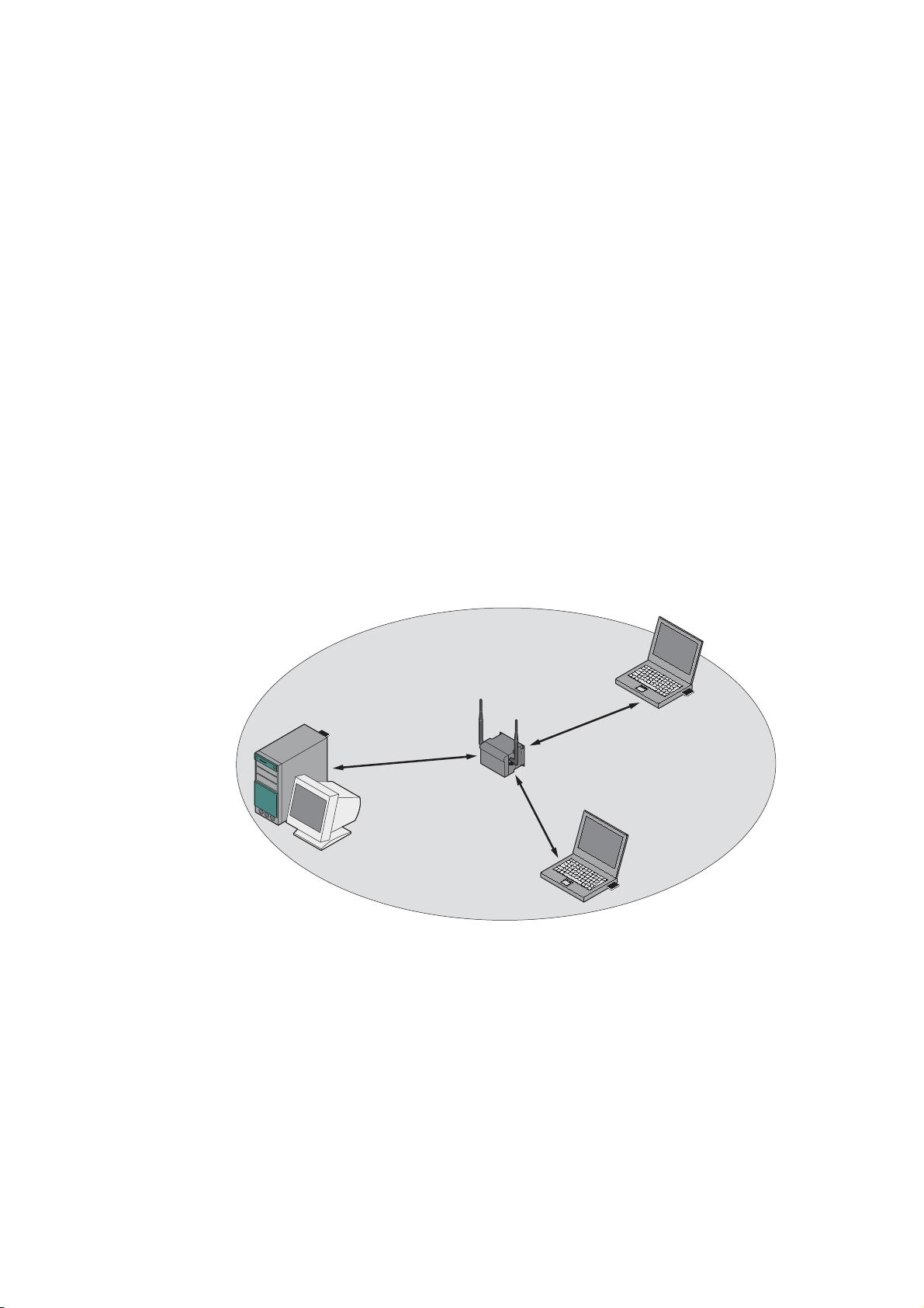
Standalone configuration with the SCALANCE W78x
This configuration does not require a server and the SCALANCE W78x does not have a
connection to a wired Ethernet. Within its transmission range, the SCALANCE W78x
forwards data from one WLAN node to another.
The wireless network has a unique name. All the devices exchanging data within this
network must be configured with this name.
2
Figure 2-1 Standalone configuration of a SCALANCE W78x. The gray area indicates the wireless
transmission range of the SCALANCE W78x.
SCALANCE W786-xPRO
Operating Instructions, Release 08/2007, C79000-G8976-C221-02
13
Page 14
Description
2.1 Network structures
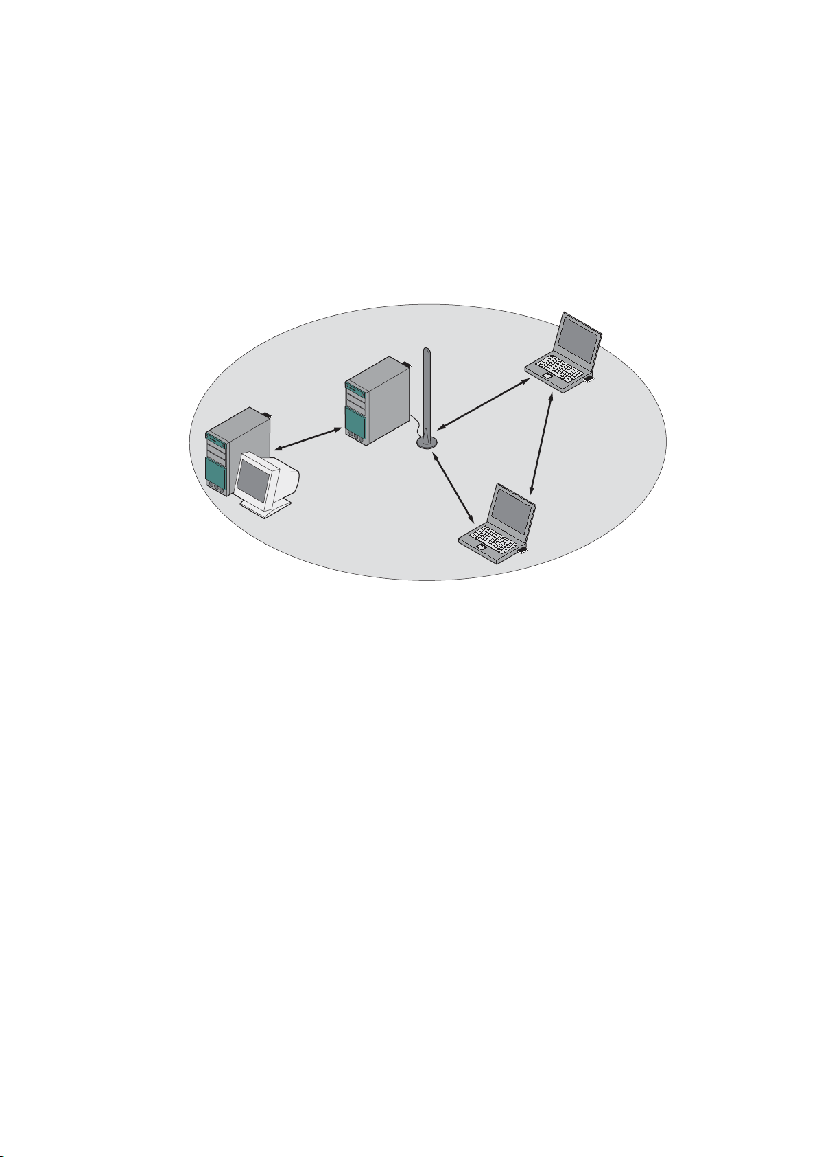
Ad hoc networks
In ad hoc mode, nodes communicate with each other directly (connection 4) without
involving a SCALANCE W78x. The nodes access common resources (files or even devices,
for example printers) of the server (connections 1 to 3 in the figure). This is, of course, only
possible when the nodes are within the wireless range of the server or within each other's
range.
2
1
4
3
Figure 2-2 Ad hoc network without SCALANCE W78x
SCALANCE W786-xPRO
14 Operating Instructions, Release 08/2007, C79000-G8976-C221-02
Page 15
Description
2.1 Network structures
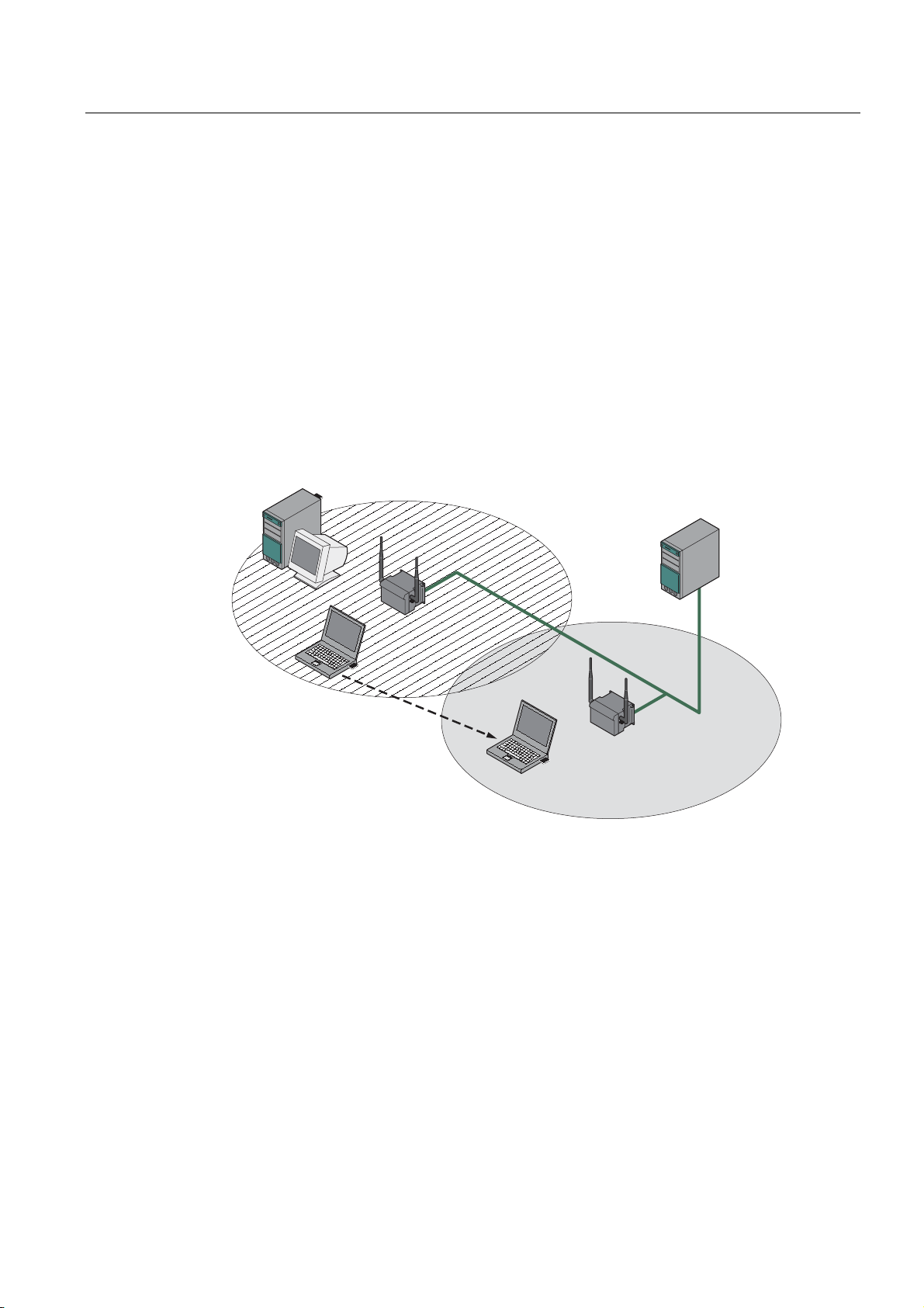
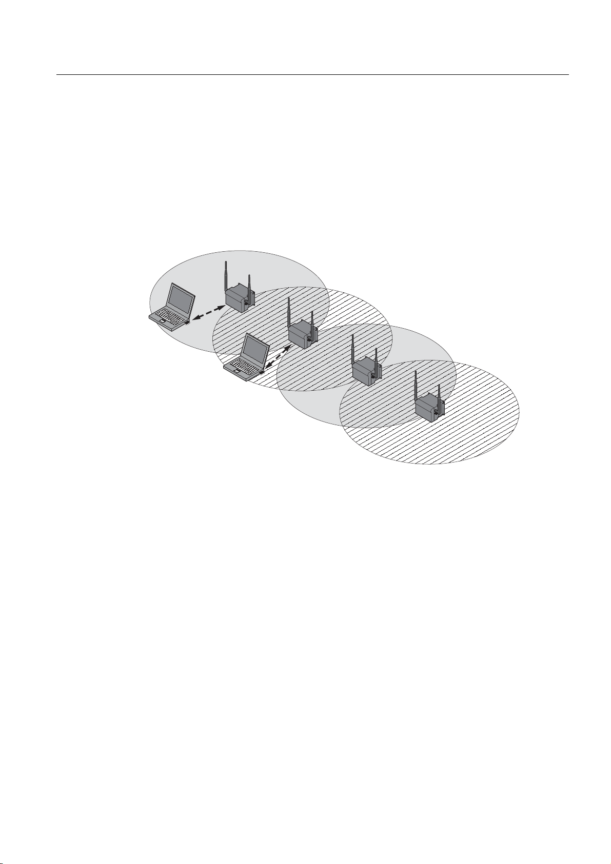
Wireless access to a wired Ethernet network
If one (or more) SCALANCE W78x access points have access to wired Ethernet, the
following applications are possible:
● A single SCALANCE W78x as gateway:
A wireless network can be connected with a wired network over a SCALANCE W78x.
● Span of wireless coverage for the wireless network with several SCALANCE W78x
access points:
The SCALANCE W78x access points are all configured with the same unique SSID
(network name). All nodes that want to communicate over this network must also be
configured with this SSID.
If a mobile station moves from the coverage range (cell) of one SCALANCE W78x to the
coverage range (cell) of another SCALANCE W78x, the wireless connection is
maintained (this is called roaming).
Figure 2-3 Wireless connection of a mobile station over two cells (roaming)
SCALANCE W786-xPRO
Operating Instructions, Release 08/2007, C79000-G8976-C221-02
15
Page 16
Description
2.1 Network structures
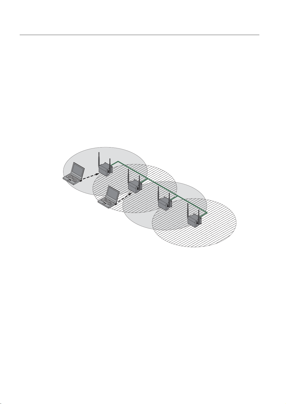
Multichannel configuration
If neighboring SCALANCE W78x access points use the same frequency channel, the
response times are longer due to the collisions that occur. If the configuration shown in the
figure is implemented as a single-channel system, computers A and B cannot communicate
at the same time with the SCALANCE W78x access points in their cells.
If neighboring SCALANCE W78x access points are set up for different frequencies, this
leads to a considerable improvement in performance. As a result, neighboring cells each
have their own medium available and the delays resulting from time-offset transmission no
longer occur.
Channel spacing should be as large as possible; a practical value would be 25 MHz (five
channels). Even in a multichannel configuration, all SCALANCE W78x access points can be
configured with the same network name.
1
A
2
1
B
2
Figure 2-4 Multichannel configuration on channels 1 and 7 with four SCALANCE W78x access
points
SCALANCE W786-xPRO
16 Operating Instructions, Release 08/2007, C79000-G8976-C221-02
Page 17
Description
2.1 Network structures
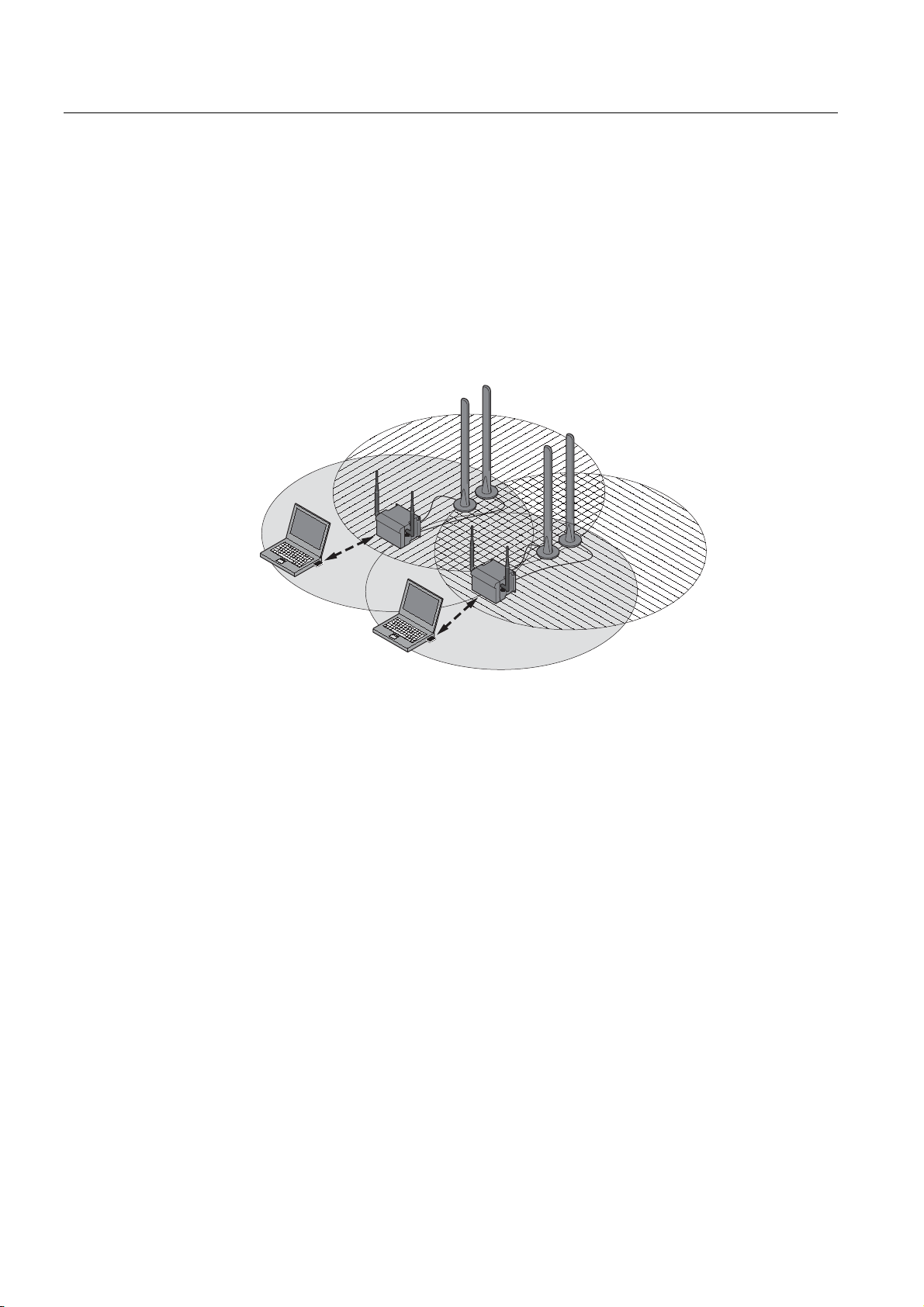
Wireless Distribution System (WDS)
WDS allows direct connections between SCALANCE W78x devices and or between
SCALANCE W78x and other WDS-compliant devices. These are used to create a wireless
backbone or to connect an individual SCALANCE W78x to a network that cannot be
connected directly to the cable infrastructure due to its location.
Two alternative configurations are possible. The WDS partner can be configured both using
its name and its MAC address.
1
A
1
1
B
1
Figure 2-5 Implementation of WDS with four SCALANCE W78x access points
SCALANCE W786-xPRO
Operating Instructions, Release 08/2007, C79000-G8976-C221-02
17
Page 18
Description
2.1 Network structures
Redundant Wireless LAN (RWLAN)
RWLAN allows a redundant, wireless connection between two SCALANCE W78x devices
with at least two WLAN interfaces. This is used to set up a redundant wireless backbone that
cannot be implemented as a wired network due to its location but nevertheless has high
demands in terms of availability.
Two alternative configurations are possible. The RWLAN partner can be configured both
using its name and its MAC address.
B
A
Figure 2-6 Implementing RWLAN with two SCALANCE W78x devices with at least two WLAN
interfaces. As an alternative, data transfer is possible over one of the two wireless
adapters.
SCALANCE W786-xPRO
18 Operating Instructions, Release 08/2007, C79000-G8976-C221-02
Page 19

Description
2.2 Scope of delivery
2.2 Scope of delivery
The following components are supplied with the SCALANCE W786:
● SCALANCE W786
● 5 caps for the cover screws
● Depending on the version, up to 8 plugs for sealing the housing.
● Depending on the version, up to 8 strain relief clamps
● 1 connector for the 48 V DC power supply
● 2 adhesive sealing foils for oval fiber-optic cables
(not for devices with RJ-45 port)
● 1 SIMATIC NET Industrial Wireless LAN CD with these Operating Instructions for the
SCALANCE W78x
● 1 Operating Instructions (compact) SCALANCE W786
Please check that the consignment you have received is complete. If it is not complete,
please contact your supplier or your local Siemens office.
SCALANCE W786-xPRO
Operating Instructions, Release 08/2007, C79000-G8976-C221-02
19
Page 20

Description
2.3 Product properties
2.3 Product properties
Possible applications of the SCALANCE W786
The SCALANCE W786 is equipped with an Ethernet port and up to three wireless LAN ports.
This makes the device suitable for the following applications:
● The SCALANCE W786 forwards data within its transmission range from one node to
another without a connection to wired Ethernet being necessary.
● The SCALANCE W786 can be used as a gateway from a wired to a wireless network.
● The SCALANCE W786 can be used as a wireless bridge between two networks.
● The SCALANCE W786 can be used as a bridge between two cells operating at different
frequencies.
With a SCALANCE W786 with more than one WLAN port, you can also implement a
redundant wireless connection to a SCALANCE W78x with at least two WLAN ports.
Properties of the SCALANCE W786
● The Ethernet interface supports 10 Mbps and 100 Mbps, both in full and half duplex as
well as autocrossing and autopolarity.
● Operating the wireless interface in the frequency bands 2.4 GHz and 5 GHz.
● The wireless interface is compatible with the standards IEEE 802.11a, IEEE 802.11h,
IEEE 802.11b and IEEE 802.11g. In the 802.11a, 802.11h and 802.11g mode, the gross
transmission rate is up to 54 Mbps. In turbo mode, the transmission rate is up to 108
Mbps (not permitted in all countries and modes).
● As an expansion of the 802.11a mode, it is also possible to operated according to the
IEEE 802.11h standard. In 802.11h mode, the procedures Transmit Power Control (TPC)
and Dynamic Frequency Selection (DFS) are used in the range 5.25 - 5.35 and 5.47 -
5.75 GHz. In some countries, this allows the frequency subband of 5.47 - 5.725 GHz to
be used outdoors even with a higher transmit power.
TPC is a technique of controlling the transmit power by reducing it to the strength actually
required. With dynamic frequency selection (DFS), the access point searches for primary
users (for example radar) on a randomly selected channel before starting communication.
If signals are found on the channel, this channel is disabled for 30 minutes and the
availability check is repeated on another channel.
● Support of the authentication standards WPA, WPA-PSK, WPA2, WPA2-PSK and
IEEE 802.1x and the encryption methods WEP, AES and TKIP.
● Suitable for inclusion of a RADIUS server for authentication.
● Device-related and application-related monitoring of the wireless connection.
● The interoperability of the devices with Wi-Fi devices of other vendors was tested
thoroughly.
Note
In client mode, you can use a SCALANCE W786-xPRO with the functionality of a
SCALANCE W746-1PRO.
SCALANCE W786-xPRO
20 Operating Instructions, Release 08/2007, C79000-G8976-C221-02
Page 21

Description
2.3 Product properties
The following table illustrates the differences between the various variants of the
SCALANCE W786:
Type Number of
WLAN ports
W786-1PRO 1 1 RJ-45 1
W786-1PRO 1 1 RJ-45 — 2 6GK5786-
W786-1PRO 1 1 ST duplex
W786-1PRO 1 1 ST duplex
W786-2PRO 2 1 RJ-45 2
W786-2PRO 2 1 RJ-45 — 4 6GK5786-
W786-2PRO 2 1 ST duplex
W786-2PRO 2 1 ST duplex
Number and
type of
Ethernet ports
multimode FO
cable
multimode FO
cable
multimode FO
cable
multimode FO
cable
Number of
internal
antennas
Number of RSMA sockets
for external
Order no.
antennas
— 6GK5786-
(diversity
)
(2)
1BA60-2AA0
6GK5786-
1BA60-2AB0
(1)
1AA60-2AA0
6GK5786-
1AA60-2AB0
(1)
1
(diversity
(2)
— 6GK5786-
)
1BB60-2AA0
6GK5786-
1BB60-2AB0
(1)
— 2 6GK5786-
1AB60-2AA0
6GK5786-
1AB60-2AB0
(1)
— 6GK5786-
(diversity
)
(2)
2BA60-2AA0
6GK5786-
2BA60-2AB0
(1)
2AA60-2AA0
6GK5786-
2AA60-2AB0
(1)
2
(diversity
(2)
— 6GK5786-
)
2BB60-2AA0
6GK5786-
2BB60-2AB0
(1)
— 4 6GK5786-
2AB60-2AA0
6GK5786-
2AB60-2AB0
(1)
SCALANCE W786-xPRO
Operating Instructions, Release 08/2007, C79000-G8976-C221-02
21
Page 22

Description
2.3 Product properties
Type Number of
WLAN ports
W786-3PRO 3 1 RJ-45 — 6 6GK5786-
W786-3PRO 3 1 ST duplex
(1) US variant
(2) There are two internal antennas per WLAN port. The antenna used is always the one that
provides the best possible data transmission (diversity).
Requirements for installation and operation
A PG/PC with a network attachment must be available to configure the SCALANCE W786. If
no DHCP server is available, a PC on which the Primary Setup Tool (PST) is installed is
necessary for the initial assignment of an IP address to the SCALANCE W786. For the other
configuration settings, a computer with Telnet or an Internet browser is necessary.
Number and
type of
Ethernet ports
multimode FO
cable
Number of
internal
antennas
— 6 6GK5786-
Number of RSMA sockets
for external
antennas
Order no.
3AA60-2AA0
6GK5786-
3AA60-2AB0
(1)
3AB60-2AA0
6GK5786-
3AB60-2AB0
(1)
SCALANCE W786-xPRO
22 Operating Instructions, Release 08/2007, C79000-G8976-C221-02
Page 23
Description
2.4 LED display
2.4 LED display
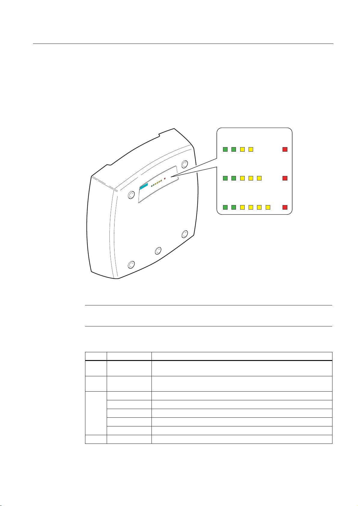
Information on operating status and data transfer
On the front of the housing, several LEDs provide information on the operating status of the
SCALANCE W786:
SCALANCE W786-1x
s
1
R
PoE
1P1
L
SCALANCE W786-3
3F
R
2
R
P1
PoE
L1
R1
SCALANCE W786-2x
PoE
P1
L1
R1 R2
SCALANCE W786-3x
P1
R1 R2
PoE
L1
R3
F
F
F
Figure 2-7 The LED display of the SCALANCE W786
Note
The "PoE" LED does not exist on devices with a port for FO cable.
LED Color Description
L1 Green Power supply over a power supply adapter or the 48 V DC energy
contacts of devices with a port for FO cable.
PoE Green Power over Ethernet or power over the 48 V DC energy contacts of
devices with an RJ-45 port.
P1
R1 Yellow Data transfer over the first WLAN interface.
Yellow Data transfer over the Ethernet interface (traffic).
Green There is a connection over the Ethernet port. (Link).
Flashing yellow PRESET-PLUG detected.
Yellow/green PRESET function completed successfully.
Flashing green "Flashing" enabled over PST.
SCALANCE W786-xPRO
Operating Instructions, Release 08/2007, C79000-G8976-C221-02
23
Page 24

Description
2.4 LED display
LED Color Description
Green
Flashing green
Green flashing
quickly
Green
3x fast,
1x long flashing
Flashing yellow PRESET-PLUG detected.
Yellow/green PRESET function completed successfully.
R2
R3 Yellow
Yellow
Green
Flashing green
Green flashing
quickly
Flashing yellow PRESET-PLUG detected.
Yellow/green PRESET function completed successfully.
Access Point Mode:
The WLAN interface is initialized and ready for operation.
Client Mode:
There is a connection over the first WLAN port.
Access Point Mode:
The channels are being scanned.
Client Mode:
The client is searching for a connection to an access point or ad hoc
network.
Access Point Mode:
With 802.11h, the channel is scanned for one minute for primary users
before the channel can be used for data traffic.
Client Mode:
The client waits for the adopt MAC address due to the setting <Auto Find
Adopt MAC> and is connected to no access point.
Client Mode:
The client waits for the adopt MAC address due to the setting <Auto Find
Adopt MAC> and is connected to an access point.
Access Point Mode:
Data transfer over the second WLAN port.
Client Mode:
The LED is always off because the 2nd port is not available in client
mode.
Access Point Mode:
The WLAN interface is initialized and ready for operation.
Client Mode:
The LED is always off because the 2nd port is not available in client
mode.
Access Point Mode:
The channels are being scanned.
Client Mode:
The LED is always off because the 2nd port is not available in client
mode.
Access Point Mode:
With 802.11h, the channel is scanned for one minute for primary users
before the channel can be used for data traffic.
Client Mode:
The LED is always off because the 2nd port is not available in client
mode.
Access Point Mode:
Data transfer over the third WLAN port.
Client Mode:
The LED is always off because the 3rd port is not available in client
mode.
SCALANCE W786-xPRO
24 Operating Instructions, Release 08/2007, C79000-G8976-C221-02
Page 25

Description
2.4 LED display
LED Color Description
Green
Flashing green
Green flashing
quickly
Flashing yellow PRESET-PLUG detected.
Yellow/green PRESET function completed successfully.
Red An error occurred during operation with the SCALANCE W786. F
Flashing red Ready to load firmware. The device was either stopped with the reset
Access Point Mode:
The WLAN interface is initialized and ready for operation.
Client Mode:
The LED is always off because the 3rd port is not available in client
mode.
Access Point Mode:
The channels are being scanned.
Client Mode:
The LED is always off because the 3rd port is not available in client
mode.
Access Point Mode:
With 802.11h, the channel is scanned for one minute for primary users
before the channel can be used for data traffic.
Client Mode:
The LED is always off because the 3rd port is not available in client
mode.
button or there is incorrect firmware on the device.
Note
If the LED for the WLAN port is not green when the device starts up, although it is activated,
the port is not ready for operation (interface not initialized).
The main reason for this is usually that during commissioning of the SCALANCE W78x
products, a waiting time of up to 15 minutes can occur when the ambient temperature is
below zero. The device is ready for operation at the specified ambient temperature as soon
as the LED for the WLAN interface is lit green.
SCALANCE W786-xPRO
Operating Instructions, Release 08/2007, C79000-G8976-C221-02
25
Page 26

Description
2.5 C-PLUG
2.5 C-PLUG
Configuration information on the C-PLUG
The C-PLUG is used to transfer the configuration of the old device to the new device when a
device is replaced. When the new device starts up with the C-PLUG, it then continues
automatically with exactly the same configuration as the old device. One exception to this
can be the IP configuration if it is set over DHCP and the DHCP server has not been
reconfigured accordingly.
Reconfiguration is necessary if you use WDS or redundancy with devices with more than
one WLAN interface and use the MAC addresses and not the sysNames. These functions
are then based on the MAC address that inevitably changes if a device is replaced.
Note
In terms of the C-PLUG, the SCALANCE W-700 devices work in two modes:
• Without C-PLUG
The device stores the configuration in internal memory. This mode is active when no CPLUG is inserted.
• With C-PLUG
The configuration stored on the C-PLUG is displayed over the user interfaces. In this
mode, the internal memory is neither read nor written. If changes are made to the
configuration, the device stores the configuration directly on the C-PLUG. This mode is
active when no C-PLUG is inserted. As soon as the device is started with a C-PLUG
inserted, the SCALANCE W-700 starts up with the configuration data on the C-PLUG.
SCALANCE W786-xPRO
26 Operating Instructions, Release 08/2007, C79000-G8976-C221-02
Page 27
Description
2.6 Reset button
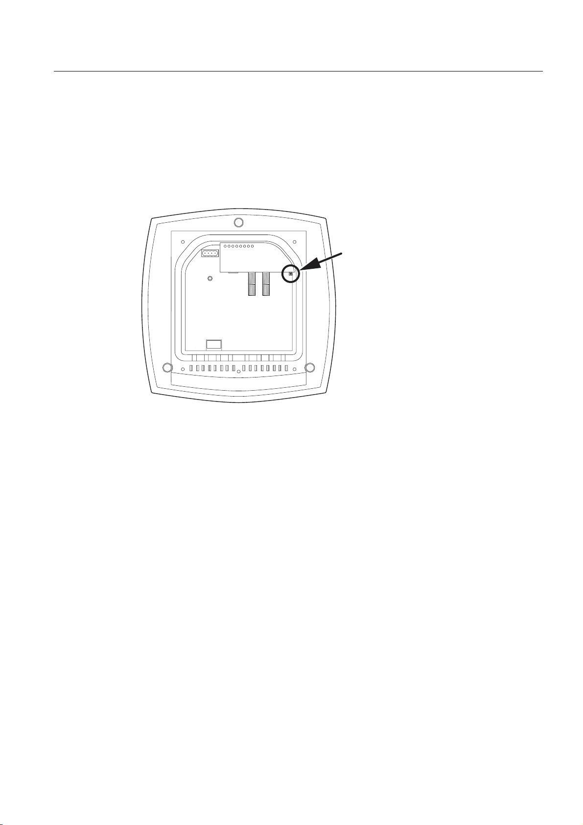
2.6 Reset button
Functions of the reset button
The reset button is located below the housing cover beside the sockets for external
antennas.
Figure 2-8 Position of the reset button with the housing cover removed
The reset button has the following functions:
● Restart of the device
To restart the device, press the reset button.
● Loading new firmware
If the normal procedure with the Load & Save menu of Web Based Management was
completed successfully, the reset button can be used to load new firmware. This situation
can occur if there was a power outage during the normal firmware update.
● Restoring the default parameters (factory defaults)
● Adopting the configuration data from the PRESET PLUG.
SCALANCE W786-xPRO
Operating Instructions, Release 08/2007, C79000-G8976-C221-02
27
Page 28

Description
2.7 Biological compatibility
2.7 Biological compatibility
Electromagnetic fields and health
With regard to the question of whether electromagnetic fields (for example in association
with industrial wireless LANs) can put human health at risk, we refer to a publication of
BITKOM (German Association for information Technology, Telecommunication and New
Media e. V.), dated December 2003:
"The same health guidelines apply to WLAN devices as to all other radio applications. These
regulations are based on the protection concept of ICNIRP
1
or the corresponding
recommendation of the European Council.
The independent German radiation protection commission (SSK) was commissioned by the
federal German ministry of the environment to investigate the possible dangers - thermal and
non-thermal - resulting from electromagnetic fields and came to the following conclusions
2
:
'The German Commission on Radiological Protection concludes that according to the latest
scientific literature no new scientific research is available with respect to proven health
hazards which would throw doubt upon the scientific evaluation which serves as the basis for
the ICNIRP safety concepts and the recommendations of the EU commission.'
The SSK also concludes that below the current limit values, these is also no scientific
suspicion of health risks.
This assessment agrees with those of other national and international scientific commissions
and of the WHO (www.who.int/emf).
Accordingly and in view of the fact that WLAN devices are significantly below the
scientifically established limit values, there are no health risks from the electromagnetic fields
of WLAN products.
1
International Council on Non-Ionizing Radiation Protection
2
'Limit Values and Precautionary Measures to Protect the General Public from
Electromagnetic Fields' Recommendation of the Radiation Protection Commission (SSK)
with scientific justification, Issue 29, 2001."
You will find further information on this topic under the following URL:
www.bitkom.org
SCALANCE W786-xPRO
28 Operating Instructions, Release 08/2007, C79000-G8976-C221-02
Page 29

Assembly
3.1 Removing / fitting the housing cover
When does the housing cover need to be removed?
You can only perform the following activities when the cover is removed.
● You want to screw the SCALANCE W786 to a wall or onto the optional mounting plate.
● You want to connect cables to the SCALANCE W786 for the power supply, for Ethernet
or for external antennas.
● You want to insert a C-PLUG in the device or replace an existing C-PLUG.
● You want to use the reset button.
Removing the housing cover
WARNING
Danger from line voltage
After removing the housing cover, there is a risk of touching live parts.
3
Remove the housing cover only after you have turned off the power supply of the
SCALANCE W786.
SCALANCE W786-xPRO
Operating Instructions, Release 08/2007, C79000-G8976-C221-02
29
Page 30
Assembly
3.1 Removing / fitting the housing cover
6-3
78
F
SCALANCE W
R3
R2
R1
PoE
L1 P1
s
C
B
A
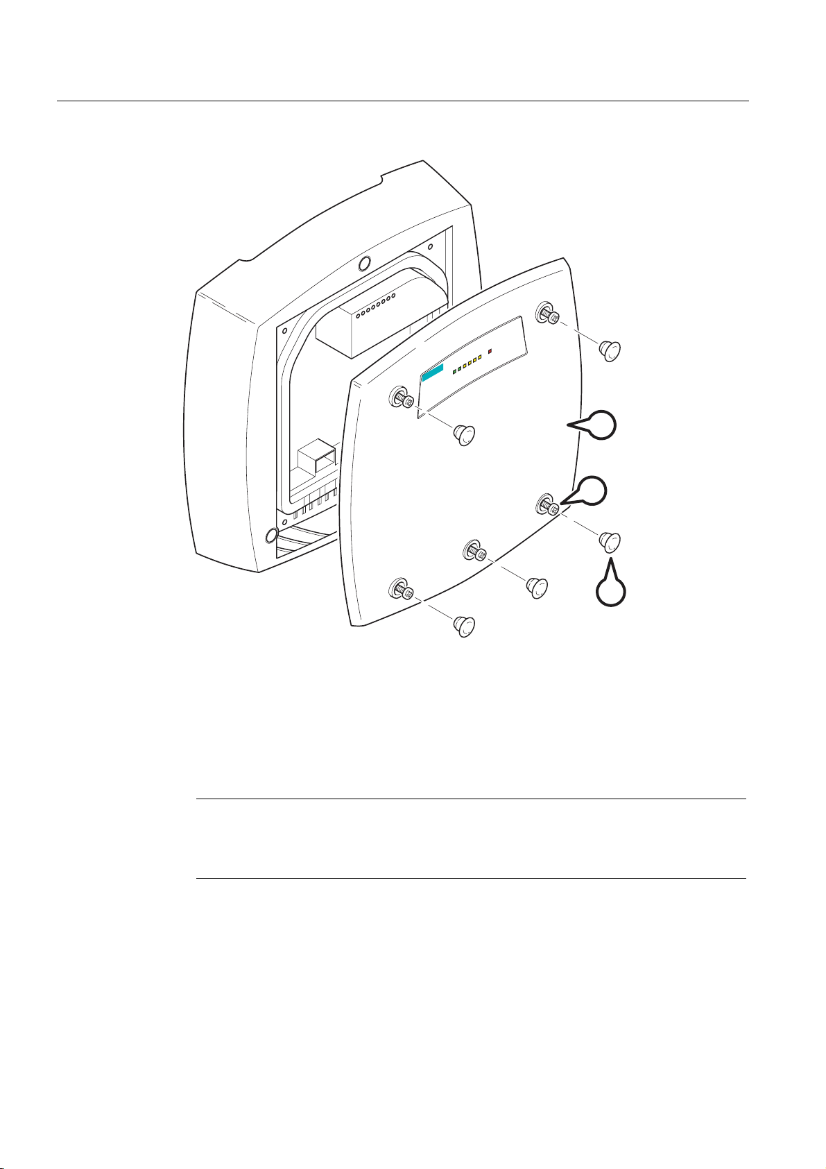
Figure 3-1 Removing the cover
A Sealing cap
B Cover screw
C Housing cover
Follow the steps below to remove the housing cover:
1. Remove the sealing caps from the housing cover (position A in the figure above)
2. Loosen the screws in the cover (position B in the figure above).
Note
These screws remain in the cover after they have been loosened (prevents them being
lost). Never attempt to remove these screws from the housing cover using force,
otherwise the housing cover will be damaged!
3. Remove the housing cover with the captive screws (position C in the figure above).
Fitting the housing cover
Fitting the housing cover is carried out in the reverse order. Tightening torque for the cover
screws 1.8 Nm.
SCALANCE W786-xPRO
30 Operating Instructions, Release 08/2007, C79000-G8976-C221-02
Page 31

Assembly
3.2 Connecting up cables
3.2 Connecting up cables
Connecting up cables prior to mounting
Before you screw a SCALANCE W786 to a wall or to the optional mounting plate, the cables
for the power supply, for Ethernet, and, when necessary, for the external antennas must be
connected up first. The available options are as follows:
AB C
Figure 3-2 Side view of a SCALANCE W786 with cables entering from different directions
● The cables are inserted from above (position A in the previous schematic). The housing
of the SCALANCE W786 has an opening at the top for this purpose.
● The cables are inserted from below (position B in the previous schematic). There is also
an opening at the bottom for this purpose.
● Cables inserted through a wall behind the SCALANCE W786 (position C in the previous
schematic). In this case, you will need to mount the SCALANCE W786 so that the
opening in the wall is located above the lower edge of the device.
SCALANCE W786-xPRO
Operating Instructions, Release 08/2007, C79000-G8976-C221-02
31
Page 32

Assembly
3.2 Connecting up cables
Connecting up FO cables
Fiber-optic cables have a minimum bending radius. The cable must not be bent tighter than
this bending radius during installation or operation, otherwise the FO cable will be irreperably
damaged.
R > 25 mm
A
R*
Figure 3-3 Connecting up an FO cable
For the FO cable, use the second opening from the left in the seal. Cable routing is
illustrated in the figure above. For individual cores immediately following the connector, the
minimum bending radius is 25 mm. Refer to the specification of the cable you are using for
the minimum permitted bending radius of the cable within the jacket. Make sure that the FO
cable is not sharply kinked after passing through the housing.
An adhesive sealing foil must be used in the housing sealing with FO cables (position A in
the figure above). For more detailed information, refer to the section "Connecting the
cables".
SCALANCE W786-xPRO
32 Operating Instructions, Release 08/2007, C79000-G8976-C221-02
Page 33

Assembly
3.2 Connecting up cables
Grounding terminal
WARNING
To operate the SCALANCE W786 safely, the chassis ground connector must have a
suitable cable connected. Do not use the SCALANCE W786 without a ground cable
connected.
The chassis ground connector is located on the rear of the device (M4 thread). Connect the
ground cable before you mount the SCALANCE W786 on a wall or on the optional mounting
plate. Once the SCALANCE W786 is mounted, the connector is no longer accessible.
Place the supplied toothed washer directly on the rear of the device before screwing on the
ground cable. Only then can you be sure that there is ideal contact with the screwed-on
cable.
Figure 3-4 Chassis ground connector on the rear of the SCALANCE W786
SCALANCE W786-xPRO
Operating Instructions, Release 08/2007, C79000-G8976-C221-02
33
Page 34

Assembly
3.3 Mounting without an adapter (wall mounting only)
3.3 Mounting without an adapter (wall mounting only)
Drilling template
The location of the holes for mounting the SCALANCE W786 on a wall is shown in the
following figure:
19
187
46
34
Figure 3-5 Drilling template for wall mounting of the SCALANCE W786
184
34
SCALANCE W786-xPRO
34 Operating Instructions, Release 08/2007, C79000-G8976-C221-02
Page 35

Assembly
3.3 Mounting without an adapter (wall mounting only)
Procedure
B
A
Figure 3-6 SCALANCE W786 wall mounting
Follow the steps below to screw a SCALANCE W786 to a wall:
1. Lead the cables into the housing of the SCALANCE W786 (position A in the figure
above). Note the information in the section "Connecting up cables".
2. Secure the SCALANCE W786 to the wall with three screws (position B in the figure
above). The screws are not supplied with the device. The type and length of the screws
depend on the type of wall.
Type of screw:
– for wooden walls: wood screw 4 x 30 mm
– for concrete walls: 4 x 50 mm with 5 mm concrete plug
– for metal walls: M4 x 25 mm with machine thread in the wall
SCALANCE W786-xPRO
Operating Instructions, Release 08/2007, C79000-G8976-C221-02
35
Page 36

Assembly
3.3 Mounting without an adapter (wall mounting only)
Option: Threaded holes on rear of housing
When a wall is extremely thin, it is often not possible to use wall plugs for the screws. To
allow wall mounting even in this situation, there are four M4 threaded holes on the rear of the
SCALANCE W786. The drilling template is a square with sides 100 mm long. The device can
therefore be mounted on a wall with bolts through the wall.
Calculate the length of the required M4 screws as follows:
Screw length = wall thickness + 7 mm
SCALANCE W786-xPRO
36 Operating Instructions, Release 08/2007, C79000-G8976-C221-02
Page 37

Assembly
3.4 Mounting with mounting plate
3.4 Mounting with mounting plate
3.4.1 Fitting the mounting plate to a wall
Drilling template
The location of the holes for fitting the mounting plate to a wall is shown in the following
figure:
62
Procedure
109
81
46
Figure 3-7 Drilling template for fitting the mounting plate to a wall
Secure the mounting plate to the wall with four screws. The screws are not supplied with the
device. The type and length of the screws depend on the type of wall.
Type of screw:
● for wooden walls: wood screw 4 x 30 mm
160
46
● for concrete walls: 4 x 50 mm with 5 mm concrete plug
● for metal walls: M4 x 25 mm with machine thread in the wall
SCALANCE W786-xPRO
Operating Instructions, Release 08/2007, C79000-G8976-C221-02
37
Page 38

Assembly
3.4 Mounting with mounting plate
Figure 3-8 Fitting the mounting plate for the SCALANCE W786 to a wall
3.4.2 Screwing the cover plate for the cable feedthrough to the mounting plate
Protection of the cable feedthrough against strong water jets
The cabling of a SCALANCE W786 is led out of the rear of the device. The housing seal is
effective only when it is not subjected to water jets. If the device is mounted on a wall, this is
the case and no further measures are necessary. When mounted in any other way, except
for mounting on an S7-300 standard rail, an additional cover plate must be screwed to the
mounting plate.
WARNING
Danger from line voltage
If the cable feedthrough is subjected to strong water jets, water can penetrate the device
and create a live connection to the line voltage. There is then a risk of electric shock.
Make sure that you use the cover plate for the cable feedthrough if you do not mount the
SCALANCE W786 on a wall.
SCALANCE W786-xPRO
38 Operating Instructions, Release 08/2007, C79000-G8976-C221-02
Page 39

Assembly
3.4 Mounting with mounting plate
Procedure
1
2
A
A
Figure 3-9 Fitting and securing the cover plate for the cable feedthrough
To screw the cover plate for the cable feedthrough to the mounting plate, follow the steps
below:
1. Fit the cover plate on the mounting plate from below until the two lugs (position A in the
figure above) engage the lower edge of the mounting plate.
2. Secure the cover plate to the mounting plate with two M4 screws. The screws are
supplied with the assembly kit.
SCALANCE W786-xPRO
Operating Instructions, Release 08/2007, C79000-G8976-C221-02
39
Page 40

Assembly
3.4 Mounting with mounting plate
3.4.3 Fitting the mounting plate to an S7-300 standard rail
Procedure
A
B
Figure 3-10 Side view of a mounting plate on an S7-300 standard rail
Follow the steps below to fit the mounting plate to an S7-300 standard rail:
1. Place the mounting plate with the two protruding catches on the top edge of the S7-300
standard rail (position A in the figure above).
2. At the bottom, the mounting plate has two lugs with holes. Screw the lugs to the S7-300
standard rail (position B in the figure above). The required screws are supplied with the
mounting plate.
SCALANCE W786-xPRO
40 Operating Instructions, Release 08/2007, C79000-G8976-C221-02
Page 41

Assembly
3.4 Mounting with mounting plate
3.4.4 Fitting the mounting plate to a DIN rail
Procedure
A
A
B
Figure 3-11 Mounting plate with fittings for DIN rail mounting
Follow the steps below to fit the mounting plate to a DIN rail:
1. Place the mounting plate with the two catches (position A in the figure above) on the
upper edge of the DIN rail.
2. Pull down the DIN rail sliding catch (position B in the figure above) and press the
mounting plate against the DIN rail until the sliding catch engages.
SCALANCE W786-xPRO
Operating Instructions, Release 08/2007, C79000-G8976-C221-02
41
Page 42

Assembly
3.4 Mounting with mounting plate
3.4.5 Fitting the mounting plate to a mast
Procedure
A
B
Figure 3-12 Mounting plate with fittings for mast mounting
Follow the steps below to fit the mounting plate to a mast:
1. Feed the fastening straps through the openings in the mounting plate (position A in the
figure above).
2. Place the fastening straps around the mast at the required position.
3. Feed the free end of the strap through the quick-release fastener. You can twist the
tensioning screw (position B in the figure above) to the side to adapt a fastening strap to
the diameter of the mast.
4. Press the tensioning screw against the fastening strap and tighten the tensioning screw,
tightening torque 4.5 Nm.
SCALANCE W786-xPRO
42 Operating Instructions, Release 08/2007, C79000-G8976-C221-02
Page 43

Assembly
3.4 Mounting with mounting plate
3.4.6 Fitting/removing the SCALANCE W786 to/from a mounting plate
Procedure for mounting the device
1
B
C
A
2
Figure 3-13 Fitting the SCALANCE W786 to a mounting plate
Follow the steps below to fit a SCALANCE W786 to a mounting plate:
1. Lead the cables into the housing of the SCALANCE W786 (position A in the figure
above). Note the information in the section "Connecting up cables".
2. Fit the SCALANCE W786 so that the upper edge of the rear of the housing is below the
two catches of the mounting plate (position B in the figure above).
3. Push in the SCALANCE W786 until it engages in the notches at the lower edge of the
mounting plate (position C in the figure above).
SCALANCE W786-xPRO
Operating Instructions, Release 08/2007, C79000-G8976-C221-02
43
Page 44

Assembly
3.4 Mounting with mounting plate
C
Figure 3-14 Screwing a SCALANCE W786 to a mounting plate
4. Screw the SCALANCE W786 using the three M4 screws supplied with the mounting plate
(position D in the figure above), tightening torque 1.8 Nm.
Procedure for removing the device
Follow the steps below to remove a SCALANCE W786 from a mounting plate:
1. Loosen the screws between the SCALANCE W786 and mounting plate.
2. Using a screwdriver or similar tool, press down the two lugs on the lower edge of the
mounting plate (position C in the first figure in this section) and release the SCALANCE
W786 from the recesses.
3. Pull out the lower edge of the SCALANCE W786 to the front and then release it from the
two clips on the mounting plate (position B in the first figure in this section).
SCALANCE W786-xPRO
44 Operating Instructions, Release 08/2007, C79000-G8976-C221-02
Page 45

Connecting up
4.1 Lightning protection, power supply, and grounding
Notes on lightning protection
WARNING
Danger due to lightning strikes
Antennas installed outdoors must be within the area covered by a lightning protection
system. Make sure that all conducting systems entering from outdoors can be protected by
a lightning protection potential equalization system.
When implementing your lightning protection concept, make sure you adhere to the VDE
0182 or IEC 62305 standard.
A suitable lightning conductor is available in the range of accessories of SIMATIC NET
Industrial WLAN:
Lightning protector LP798-1N (order no. 6GK5798-2LP00-2AA6)
4
WARNING
Danger due to lightning strikes
Installing this lightning protector between an antenna and a SCALANCE W-700 is not
adequate protection against a lightning strike. The LP798-1N lightening protector only
works within the framework of a comprehensive lightning protection concept. If you have
questions, ask a qualified specialist company.
Note
The requirements of EN61000-4-5, surge immunity tests on power supply lines, are met only
when a Blitzductor is used with 12 - 24 V DC and 48 V DC:
12 - 24 V DC: VT AD 24V type no. 918 402
48 V DC: Type no. 919 545 and 919 506 (holder)
Manufacturer: DEHN+SÖHNE GmbH+Co.KG, Hans Dehn Str. 1, Postfach 1640, D-92306
Neumarkt, Germany
SCALANCE W786-xPRO
Operating Instructions, Release 08/2007, C79000-G8976-C221-02
45
Page 46

Connecting up
4.1 Lightning protection, power supply, and grounding
Safety extra low voltage
Earthing
WARNING
Danger to life from overvoltage, fire hazard
SCALANCE W-700 devices are designed for operation with a directly connectable safety
extra-low voltage or with the power supply adapters available as accessories (available
only for the SCALANCE W786-xPRO device). Therefore only safety extra-low voltage
(SELV) with limited power source (LPS) complying with IEC950/EN60950/VDE0805 may
be connected to the power supply terminals (exception: Power supply adapter for 110 - 230
V AC for the SCALANCE W786-xPRO).
The power supply unit to supply the SCALANCE W-700 must comply with NEC Class 2
(requirements of class 2 for power supply units of the "National Electrical Code, table 11
(b)") or SELV with LPS (Limited Power Source) EN 60950-1. If the power supply is
designed redundantly (two separate power supplies), both power supplies must meet these
requirements.
Exceptions:
• Power supply with PELV (according to VDE 0100-410 or IEC 60364-4-41) is also
possible if the generated rated voltage does not exceed the voltage limits 25 V AC or 60
V DC.
CAUTION
Damage to the device due to potential differences
To avoid the influence of electromagnetic interference, the device should be grounded.
There must be no potential difference between the following parts, otherwise the device or
other connected device could be severely damaged:
• Housing of the SCALANCE W-700 and the ground potential of the antenna.
• Housing of the SCALANCE W-700 and the ground potential of a device connected over
Ethernet.
• Housing of the SCALANCE W-700 and the shield contact of the connected Ethernet
cable.
Connect both grounds to the same foundation earth or use an equipotential bonding cable.
Interruption of the power supply
SCALANCE W786-xPRO
46 Operating Instructions, Release 08/2007, C79000-G8976-C221-02
CAUTION
Damage to the Ethernet interface
Repeated fast removal and insertion of the Ethernet cable when using Power-over-Ethernet
and when there is a redundant power supply can cause damage to the Ethernet interface.
Avoid repeatedly removing and inserting the Ethernet cable when using Power-overEthernet and a redundant power supply.
Page 47

Connecting up
4.2 Suitable cables and antennas for the SCALANCE W786
4.2 Suitable cables and antennas for the SCALANCE W786
Cable specification
The following table lists the requirements for a cable depending on the use case.
Application Specification
Direct 48 V DC supply
Power supply adapter 12 - 24 V DC
Power supply adapter 110 - 230 V AC
Ethernet IE FC TP Standard Cable GP 2 x 2 (type A)
Multimode FO cable FO Standard Cable GP
• Round cable cross-section with 6 to 8 mm
diameter.
• Permitted tensile load at least 100 N.
• UL listing: Type PLTC or ITC
• Round cable cross-section with 6 to 8 mm
diameter.
• Permitted tensile load at least 100 N.
• UL listing: Type PLTC or ITC
• Round cable cross-section with 6 to 8 mm
diameter.
2
• Three-core cable with 0.5 - 1.5 mm
section of the individual cores.
• Permitted tensile load at least 100 N.
Order no. 6XV1 840-2AH10
IE TP Torsion Cable 2 x 2 (type C)
Order no. 6XV1 870-2F
IE FC TP Trailing Cable 2 x 2 (type C)
Order no. 6XV1 840 3AH10
UL listing: Type PLTC or ITC (the three named
types have this approval)
Order no. 6XV1 873-2A
Minimum bending radius 65 mm.
You will find detailed information on
preassembled cable lengths and connectors in
the catalog "IK PI".
cross
Antenna connector: N-Connect/R-SMA connecting cable
The N-Connect/R-SMA male/male flexible connecting cable is available as an accessory for
direct connection of an antenna to a SCALANCE W-700.
Length in m Order number
1
2
5
10
SCALANCE W786-xPRO
Operating Instructions, Release 08/2007, C79000-G8976-C221-02
6XV1875-5CH10
6XV1875-5CH20
6XV1875-5CH50
6XV1875-5CN10
47
Page 48

Connecting up
4.2 Suitable cables and antennas for the SCALANCE W786
Antenna connector: N-Connect/ N-Connect connecting cable
The N-Connect/N-Connect male/male flexible connecting cable is available as an accessory
for connecting an antenna to the lightning protector LP798-1N.
Length in m Order number
1
2
5
10
6XV1875-5CH10
6XV1875-5CH20
6XV1875-5CH50
6XV1875-5CN10
There is a control cabinet feedthrough available for IWLAN devices located in a control
cabinet. You will find detailed information in the catalog IK PI.
Antennas
The following antennas have been approved for use with a SCALANCE W786-xPRO:
Type Properties Order no.
ANT795-6MN Omni antenna 2.4 / 5 GHz,
ceiling mounted
ANT792-6MN Omni antenna 2.4 GHz,
wall mounted
ANT793-6MN Omni antenna 5 GHz,
wall mounted
ANT792-8DN Directional antenna 2.4 GHz,
wall mounted
ANT793-8DN Directional antenna 5 GHz,
wall mounted
ANT795-6DN Directional antenna 2.4 / 5 GHz,
wall mounted
ANT792-4DN RCoax antenna 2.4 GHz 6GK5792-4DN00-0AA6
ANT793-4MN RCoax antenna 5 GHz 6GK5793-4MN00-0AA6
6GK5795-6MN00-0AA6
6GK5792-6MN00-0AA6
6GK5793-6MN00-0AA6
6GK5792-8DN00-0AA6
6GK5793-8DN00-0AA6
6GK5795-6DN00-0AA6
SCALANCE W786-xPRO
48 Operating Instructions, Release 08/2007, C79000-G8976-C221-02
Page 49

Connecting up
4.3 Connecting the cables
4.3 Connecting the cables
Procedure
WARNING
Danger from line voltage
If the housing is not perfectly sealed, there is a danger to life due to the line voltage if the
SCALANCE W786 is subjected to spray water or dampness. Make sure that you keep to
the following safety rules.
• Before connecting up, turn of the power supply.
• The sealing of the cable feedthroughs of the SCALANCE W786 is only assured when
the cable has a suitable diameter and adequate tensile strength. Only use cables that
meet the specifications in the section "Cables for the SCALANCE W786". When
connecting up a FO cable, make sure that you use the adhesive sealing foil supplied
with the SCALANCE W786.
• Never wrap insulating tape, adhesive tape or other materials around thinner cables to
achieve the required diameter. In this case, neither the housing seal nor the strain relief
clamps can fulfill their function.
• Close all unused openings in the housing seal with the sealing plugs supplied with the
SCALANCE W786. Do not use fillers or any other material under any circumstances.
SCALANCE W786-xPRO
Operating Instructions, Release 08/2007, C79000-G8976-C221-02
49
Page 50

Connecting up
4.3 Connecting the cables
B
A
D
C
Figure 4-1 Connecting a cable and fitting the strain relief clamps
Follow the steps below to connect cables to the SCALANCE W786.
1. Connect the cables to the appropriate contacts. (Position A in the figure above) You have
the following options:
– Connect cables preassembled with a connector (Ethernet, antennas) by inserting the
connector into the appropriate socket. Secure antenna cables by tightening the sleeve
nut of the connector (key size SW8). You will find more information on this topic in the
sections "Connection for Industrial Ethernet" and "Connections for external antennas".
– 48 V DC power supply. Use the connector supplied with the SCALANCE W786. For
details of the terminal assignment, refer to the section "Connectors for the power
supply".
– 12 - 24 V DC or 110 - 230 V AC power supply. With these power supplies, you require
a power supply adapter (do not ship with the SCALANCE W786). You will find more
information in the section "Connecting a power supply adapter".
2. Fit a strain relief clamp to the connected cable. The toothed part of the clamp must
enclose the cable completely (as shown by position B in the figure above).
3. Press the strain relief clamp into the housing until the cable is located completely in the
opening in the housing seal (position C in the figure above).
SCALANCE W786-xPRO
50 Operating Instructions, Release 08/2007, C79000-G8976-C221-02
Page 51

Connecting up
4.3 Connecting the cables
4. Seal all openings not required for cables with sealing plugs (position D in the figure
above).
5. Fit these sealing plugs in a strain relief clamp. The lower surrounding notch must be
enclosed by the toothing of the strain relief clamp (as shown in the figure below). Press
the strain relief clamp into the housing until the sealing plug is located completely in the
opening of the housing seal.
Figure 4-2 Securing a sealing plug with a strain relief clamp
Note
Keep unused sealing plugs and strain relief clamps for later use.
Points to note when connecting an oval FO cable
The oval FO cable specified for use with the SCALANCE W786 does not have a circular
cross section. As a result, remember the following points when connecting up such cables.
Gasket
Fit the supplied adhesive sealing foil at the point where the cable goes through the housing
seal. Only then will you achieve perfect sealing of the housing. Follow the steps outlined
below:
1. Remove the protective foil and wind the adhesive sealing foil completely around the oval
FO cable at the appropriate position transverse to the cable.
SCALANCE W786-xPRO
Operating Instructions, Release 08/2007, C79000-G8976-C221-02
51
Page 52

Connecting up
4.3 Connecting the cables
Strain relief clamp
When you fit the strain relief clamp, make sure that the FO cable is in the correct position.
The shorter sides of the cable must make contact with the toothing of the strain relief clamp.
Figure 4-3 View from above with an FO cable inserted in the strain relief clamp
SCALANCE W786-xPRO
52 Operating Instructions, Release 08/2007, C79000-G8976-C221-02
Page 53

Connecting up
4.4 Connectors for the power supply of the SCALANCE W786
4.4 Connectors for the power supply of the SCALANCE W786
Possible power supplies
The following power supplies are suitable for the SCALANCE W786:
● 48 V DC direct voltage
Use the two-pin connector supplied with the SCALANCE W786.
● 12 - 24 V DC direct voltage
Use the power supply adapter 12 - 24 V DC available as an accessory.
● 110 - 230 V DC direct voltage
Use the power supply adapter 110 - 230 V DC available as an accessory.
● Power over Ethernet (PoE)
If an eight-wire Ethernet cable is used, it is possible to supply power over the four wires
that are not used as data lines. As an alternative, the voltage can be modulated onto the
data lines ("phantom power").
If a Fast Connect Ethernet connector is used to allow cable assembly in the field and due
to its greater mechanical strength, you can only use four-wire cables. In this case, only
phantom power is possible. This does not represent a restriction for the user because
PoE-compatible power equipment always provides both options.
Procedure for connecting the supplied connector for 48 V DC
DC 48 V
Figure 4-4 Position of the opening in the housing for the power supply with the housing cover
removed
Perform the following steps to connect a 48 V DC cable to a SCALANCE W786:
1. Connect the supplied connector to the 48 V DC cable. The figure above shows the
location of the socket in the housing and the contact assignment. The connector is safe
against polarity reversal and can only be inserted in the right-hand half of the housing
When connecting the cores, you should therefore make sure that the connector is
oriented as shown in the following figure.
SCALANCE W786-xPRO
Operating Instructions, Release 08/2007, C79000-G8976-C221-02
53
Page 54

Connecting up
4.4 Connectors for the power supply of the SCALANCE W786
Figure 4-5 Position of the connector when inserted in the socket of the housing
2. Press the connector into the socket in the housing until it engages.
3. Secure the power cable with a strain relief clamp. For more detailed information on this
topic, refer to the section "Connecting the cables".
SCALANCE W786-xPRO
54 Operating Instructions, Release 08/2007, C79000-G8976-C221-02
Page 55

Connecting up
4.5 Connecting a power supply adapter
4.5 Connecting a power supply adapter
Input voltage options
The optional power supply adapter is available in two versions:
● Power supply adapter for 12 - 24 V DC direct voltage
Note
Applies only to SCALANCE W786-3xx
If a SCALANCE W786-3xx is operated with diversity for three antenna pairs, the power
for 12 - 24 V DC cannot be supplied redundantly. In this case, there is no further opening
in the housing for a second power cable.
● Power supply adapter for 110 - 230 V AC alternating voltage
How to fit the power supply adapter
WARNING
Danger from line voltage
Power supply cables may only be connected when the power is turned off!
Start up the SCALANCE W786 only after screwing the housing cover in place again so that
protection from touching live parts is restored!
SCALANCE W786-xPRO
Operating Instructions, Release 08/2007, C79000-G8976-C221-02
55
Page 56

Connecting up
4.5 Connecting a power supply adapter
B
A
12 - 24 V 110 - 230 V
L1 M1 M2 L2 L N PE
Figure 4-6 Using a power supply adapter in a SCALANCE W786
Follow the steps below to fit and connect a power supply adapter:
1. Fit the power supply adapter in the SCALANCE W786 as shown in the figure above. The
connector on the rear of the power supply adapter must engage fully in the socket of the
housing. The entire rear surface of the power supply adapter must make contact with the
inner surface of the SCALANCE W786.
CAUTION
Only use the loop (position B in the figure above) to remove the power supply adapter
from the SCALANCE W786! This prevents the connector skewing on the back of the
power supply adapter and breaking off.
2. Connect the power supply adapter and the SCALANCE W786 with the screw supplied
with the power supply adapter (position A in the figure above).
SCALANCE W786-xPRO
56 Operating Instructions, Release 08/2007, C79000-G8976-C221-02
Page 57

Connecting up
4.5 Connecting a power supply adapter
3. Connect the cable for the power supply. The assignment of the contacts is illustrated in
the figure above.
4. Secure the power supply cable with a strain relief clamp. For more detailed information
on this topic, refer to the section "Connecting the cables".
How to remove the power supply adapter
Follow the steps below to remove a power supply adapter from a SCALANCE W786:
WARNING
Danger from line voltage
Disconnect power supply cables only when the power to the power supply adapter is turned
off!
1. Disconnect the power supply cable from the power supply adapter.
2. Loosen the securing screw of the power supply adapter (position A in the figure above).
3. Pull the loop (position B in the figure above) to remove the connector on the rear of the
power supply adapter from the socket in the housing and remove the power supply
adapter.
SCALANCE W786-xPRO
Operating Instructions, Release 08/2007, C79000-G8976-C221-02
57
Page 58

Connecting up
4.6 Connection for Industrial Ethernet
4.6 Connection for Industrial Ethernet
Device variants
With a SCALANCE W786, you have the choice of two Ethernet ports:
● RJ-45 jack
● ST duplex socket for multimode FO cables 1310 nm and a maximum cable length of
3000 m
Procedure for connecting an Ethernet cable
ST-Duplex:
TX
RX
Figure 4-7 Position of the Ethernet port with the housing cover removed
Perform the following steps to connect an Ethernet cable to a SCALANCE W786:
1. Insert the connector of the Ethernet cable in the corresponding socket of the SCALANCE
W786. If you use FO cables, make sure that the transmit and receive lines are correctly
connected. The location of the socket for RX and TX is shown in the figure above.
2. Secure the Ethernet cable with a strain relief clamp. For more detailed information on this
topic, refer to the section "Connecting the cables".
SCALANCE W786-xPRO
58 Operating Instructions, Release 08/2007, C79000-G8976-C221-02
Page 59

Connecting up
4.7 Connectors for external antennas
4.7 Connectors for external antennas
How to connect external antennas
3
A
2
1
Figure 4-8 Position of the ports for external antennas with the housing cover removed
For each WLAN port, there are two R-SMA sockets on a SCALANCE W786 to connect
external antennas. The figure above shows how the R-SMA sockets are assigned to the
WLAN ports. With a SCALANCE W786-1PRO, only the socket pair labeled "1" exists; with a
SCALANCE W786-2PRO the sockets labeled "1" and "2" exist.
Perform the following steps to connect a cable for an external antenna to a SCALANCE
W786:
1. Insert the connector on the antenna cable into the R-SMA socket and tighten the sleeve
nut on the socket (key size SW8), tightening torque 0.6 Nm. If you want to use a port for
two antennas, connect the line for antenna "B" first. After connecting the cable for
antenna "A", the socket for "B" is not easy to reach.
B
2. Screw a terminating resistor to the unused socket if you use only one antenna on a port.
3. Secure the antenna cable(s) with a strain relief clamp. For more detailed information on
this topic, refer to the section "Connecting the cables".
SCALANCE W786-xPRO
Operating Instructions, Release 08/2007, C79000-G8976-C221-02
59
Page 60

Connecting up
4.8 Inserting / removing the C-PLUG
4.8 Inserting / removing the C-PLUG
Inserting the C-PLUG
Figure 4-9 Location of the C-PLUG with the housing cover removed
The housing of the C-PLUG has a protruding ridge on the long side. The C-PLUG can only
be inserted when this ridge is at the top right. The slot in the SCALANCE W786 has a
corresponding groove at this position. Make sure that the C-PLUG is inserted completely into
the slot.
Removing the C-PLUG
Insert a screwdriver between the right-hand front edge of the C-PLUG and the slot and
release the C-PLUG.
SCALANCE W786-xPRO
60 Operating Instructions, Release 08/2007, C79000-G8976-C221-02
Page 61

Configuration / project engineering
5.1 Technical basics
5.1.1 Spanning Tree
Avoiding loops
The Spanning Tree algorithm detects redundant physical network structures and prevents
the formation of loops by disabling redundant paths. It evaluates the distance and
performance of a connection or bases the decisions on settings made by the user. Data is
then exchanged only over the remaining connection paths.
If the preferred data path fails, the Spanning Tree algorithm then searches for the most
efficient path possible with the remaining nodes.
Root bridge and bridge priority
The identification of the most efficient connection is always related to the root bridge, a
network component that can be considered as a root element of a tree-like network
structure. With the "Bridge Priority" parameter, you can influence the selection of the root
bridge. The computer with the lowest value set for this parameter automatically becomes the
root bridge. If two computers have the same priority value, the computer with the lower MAC
address becomes the root bridge.
5
Response to changes in the network topology
If nodes are added to a network or drop out of the network, this may affect the optimum path
selection for data packets. To be able to respond to such changes, the root bridge sends
configuration messages at regular intervals. You can set the interval between two
configuration messages with the "Hello Time" parameter.
Keeping configuration information up to date
With the "Max Age" parameter, you set the maximum age of configuration information. If a
bridge has information that is older than the time set in Max Age, it discards the message
and initiates recalculation of the paths.
New configuration data is not used immediately by a bridge but only after the period
specified in the "Forward Delay" parameter. This ensures that operation is started with the
new topology only after all the bridges have the required information.
SCALANCE W786-xPRO
Operating Instructions, Release 08/2007, C79000-G8976-C221-02
61
Page 62

Configuration / project engineering
5.1 Technical basics
5.1.2 iQoS
Client-specific bandwidth reservation
iQoS (Quality of Service) is technique with which clients are assigned a certain bandwidth.
Due to this assignment, there is a high probability that data transmission to these clients will
be within a defined period. This technique can be useful when response times must be
guaranteed.
5.1.3 Forced Roaming on IP Down
Functional description
"Forced Roaming on IP down" monitors the connection to a specific IP address cyclically.
This is achieved using ICMP packets (Echo Request/Reply or Ping). If the IP connection
aborts; in other words, there is no ping reply from the other end, a deauthentication frame is
sent to all WLAN clients. The relevant WLAN interface is then disabled.
The IP connection continues to be monitored and the WLAN interface is enabled again as
soon as the access point has received a ping reply from the pinged station.
The mechanism makes it possible, for example, to monitor a connection between wireless
clients and a server. If the server can no longer be reached over the access point, the clients
are deauthenticated and the WLAN interface of the access point is disabled. The clients
roam and then connect to a different access point from which the server can be reached. As
soon as the first access point can reach the server again, it re-enables its WLAN interfaces.
5.1.4 Link Check
Device-related connection monitoring
The Link Check function provides device-related connection monitoring for a maximum of ten
wireless nodes logged on at the SCALANCE W78x. This service can be compared with the
link on a wired connection. The function monitors whether the node is available over the
wireless medium. If no packet is received from the node or sent successfully after half of the
configured monitoring time, the SCALANCE W78x attempts to send a test packet to the
node.
5.1.5 Redundancy
Redundant connection between two SCALANCE W78x devices
You can configure two SCALANCE W78x devices with two wireless interfaces so that there
is a redundant wireless connection. The redundancy function causes an automatic failover to
SCALANCE W786-xPRO
62 Operating Instructions, Release 08/2007, C79000-G8976-C221-02
Page 63

Configuration / project engineering
5.1 Technical basics
the second wireless interface if no data transfer is possible on the first wireless interface.
The user is informed of the status of the redundant connection with the statuses "not
connected", "connected", or "error" (communication error).
5.1.6 IP-Alive
Application-related connection monitoring
The IP-Alive function provides application-related connection monitoring of the wireless link.
It is useful to use IP-Alive on IP connections when it is known that they are used to send
data cyclically. With IP-Alive, you specify a monitoring time for an IP address and a port. If
you do not want to monitor a particular port but rather only the data traffic from a particular IP
address, simply enter 0 in Port. This resets the monitoring with each frame from this IP
address.
In contrast to the Link Check, the SCALANCE W78x does not start any checks until the
monitoring time has elapsed. The SCALANCE W78x checks passively whether
communication took place during the specified monitoring period. As with Link Check, you
can also enter up to ten connections here.
5.1.7 MAC-based communication
Auto Find Adopt MAC / Adopt MAC manually
Frames in the direction from the client to the access point always have the MAC address of
the WLAN interface as the source MAC address. As a result, the learning table at the access
point end always has only the MAC address of the WLAN interface of the client. If the MAC
address of a device connected to the client is adopted, both the MAC-based and the IPbased frames find their destination in precisely this device.
Other nodes located downstream from the client cannot be reached. The access point
checks whether the destination MAC address matches the MAC addresses of the connected
clients. Since a client can only adopt one MAC address, the access point does not find a
match and discards the packets of several nodes.
Maximum possible number of MAC nodes downstream from the client: 1
Notes on the "Auto Find Adopt MAC" setting:
● As long as there is no link on the Ethernet interface, the device uses the MAC address of
the Ethernet interface so that it can be reached in this status. In this status, the device
can be found using the Primary Setup Tool.
● As soon as there is a link on the Ethernet interface, the device adopts the source MAC
address of the first received frame.
SCALANCE W786-xPRO
Operating Instructions, Release 08/2007, C79000-G8976-C221-02
63
Page 64

Configuration / project engineering
5.1 Technical basics
Note
From the moment that the device adopts another MAC address (whether manually or
automatically), the device no longer responds to queries of the Primary Setup Tool when
the query is received over the WLAN interface. Queries of the PST over the Ethernet
interface continue to be replied to.
Adopt Own MAC (only for W746-1 and W747-1 or W746-1PRO and W747-1RR and W78x in client
mode)
If IP-based frames need to be sent to a device connected downstream from the client, the
default setting Adopt Own Mac can be retained. The client registers with the MAC address of
its Ethernet adapter. The IP packets are broken down according to an internal table and
forwarded to the connected devices (IP mapping).
Communication at the MAC address level (ISO/OSI layer 2) is then only possible with a
component downstream from the client if its MAC address was adopted by the client.
Maximum possible number of MAC nodes downstream from the client: 1
Layer 2 tunneling (only for W746-1 and W747-1 or W746-1PRO and W747-1RR and W78x in client
mode)
With layer 2 tunneling, the client provides information about the devices downstream from it
when it registers with an access point. This makes it possible to enter the MAC addresses of
these devices in the learning table of the access point. The access point can forward MACbased frames for the devices downstream from the client to the appropriate client.
In much the same way as with WDS, a separate port is created for the L2T client over which
the Ethernet frames are sent without changing the destination MAC address.
Maximum possible number of MAC nodes downstream from the client: 8
5.1.8 IP-based communication
IP mapping (only for W746-1 and W747-1 or W746-1PRO and W747-1RR and W78x in client mode)
If there is more than one device connected downstream from the client and these should
only be addressed with IP frames, you can implement WLAN access for several devices with
one client. With IP mapping, the client maintains a table with the assignment of MAC
address and IP address to forward incoming IP frames to the correct MAC address.
Maximum possible number of IP nodes downstream from the client: 8
SCALANCE W786-xPRO
64 Operating Instructions, Release 08/2007, C79000-G8976-C221-02
Page 65

Configuration / project engineering
5.2 Assignment of an IP address
5.2 Assignment of an IP address
5.2.1 Structure of an IP address
Address classes to RFC 1518 and RFC 1519
IP address range Max. number of networks Max. number of
hosts/network
1.x.x.x through 126.x.x.x 126 16777214 A /8
128.0.x.x through 191.255.x.x 16383 65534 B /16
192.0.0.x through 223.255.255.x 2097151 254 C /24
Multicast groups D
Reserved for experiments E
An IP address consists of 4 bytes. Each byte is represented in decimal, with a dot separating
it from the previous one. This results in the following structure, where XXX stands for a
number between 0 and 255:
Class CIDR
Subnet mask
XXX.XXX.XXX.XXX
The IP address is made up of two parts, the network ID and the host ID. This allows different
subnets to be created. Depending on the bytes of the IP address used as the network ID and
those used for the host ID, the IP address can be assigned to a specific address class:
The bits of the host ID can be used to create subnets. The leading bits represent the address
of the subnet and the remaining bits the address of the host in the subnet.
A subnet is defined by the subnet mask. The structure of the subnet mask corresponds to
that of an IP address. If a "1" is used at a bit position in the subnet mask, the bit belongs to
the corresponding position in the IP address of the subnet address, otherwise to the address
of the computer.
Example of a class B network:
The standard subnet address for class B networks is 255.255.0.0; in other words, the last
two bytes are available for defining a subnet. If 16 subnets must be defined, the 3rd byte of
the subnet address must be set to 11110000 (binary notation). In this case, this results in the
subnet mask 255.255.240.0.
To find out whether two IP addresses belong to the same subnet, the two IP addresses and
the subnet mask are ANDed bit by bit. If both logic operations have the save result, both IP
addresses belong to the same subnet, for example, 141.120.246.210 and 141.120.252.108.
Outside the local area network, the distinction between network ID and host ID is of no
significance, in this case packets are delivered based on the entire IP address.
Note
In the bit representation of the subnet mask, the "ones" must be set left-justified (there must
be no "zeros" between the "ones").
SCALANCE W786-xPRO
Operating Instructions, Release 08/2007, C79000-G8976-C221-02
65
Page 66

Configuration / project engineering
5.2 Assignment of an IP address
5.2.2 Initial assignment of an IP address
Configuration options
An initial IP address for a SCALANCE W-700 cannot be assigned using Web Based
Management or the Command Line Interface over Telnet because these configuration tools
require that an IP address already exists.
The following options are available to assign an IP address to an unconfigured device
currently without an IP address:
● DHCP (default)
● STEP 7
● NCM PC
● Primary Setup Tool
Note
DHCP is enabled as default and following "Restore Factory Defaults and Restart". If a DHCP
server is available in the local area network, and this responds to the DHCP request of a
SCALANCE W-700, the IP address, subnet mask and gateway are assigned automatically
when the device first starts up. "Reset to Memory Defaults" does not delete an IP address
assigned either by DHCP or by the user.
5.2.3 Address assignment with DHCP
Properties of DHCP
DHCP (Dynamic Host Configuration Protocol) is a method for automatic assignment of IP
addresses. It has the following characteristics:
● DHCP can be used both when a device starts up and during operation.
● The assigned IP address remains valid only for a particular time known as the lease time.
Once this period has elapsed, the client must either request a new IP address or extend
the lease time of the existing IP address.
● There is normally no fixed address assignment; in other words, when a client requests an
IP address again, it normally receives a different address from the previous address. It is,
however possible, to configure the DHCP server so that it assigns a fixed address.
SCALANCE W786-xPRO
66 Operating Instructions, Release 08/2007, C79000-G8976-C221-02
Page 67

Configuration / project engineering
5.2 Assignment of an IP address
Note
DHCP uses a mechanism with which the IP address is assigned for only a short time
(lease time). If the device does not reach the DHCP server with a new request on expiry
of the lease time, the assigned IP address, the subnet mask and the gateway are
changed to static entries.
The device therefore remains accessible under the last assigned IP address even without
a DHCP server. This is not the standard behavior of office devices but is necessary for
problem-free operation of the plant.
Since the DHCP client also sends a RELEASE to the server, the server can assign this
address to a further device so that inconsistencies can occur within the network.
Remedy:
After disabling DHCP, you should therefore
• change the IP address of the device to an address not assigned by DHCP
or
• remove the IP address assigned to the device from the address pool of the DHCP
server.
Working with a mixture of dynamic address assignment and statically assigned
addresses is not advisable.
5.2.4 Address assignment with the Primary Setup Tool
Introduction
The PST (Primary Setup Tool) is capable of assigning such an address to unconfigured
devices without an IP address.
Prerequisite
This is possible only when the devices have a default Ethernet (MAC) address and are
reachable online in the network.
Note
For more detailed information, refer to the Primary Setup Tool configuration manual.
You will find the PST at Siemens Automation and Drives Service & Support on the Internet
under entry ID 19440762. The URL for this entry is:
http://support.automation.siemens.com/WW/view/en/19440762
SCALANCE W786-xPRO
Operating Instructions, Release 08/2007, C79000-G8976-C221-02
67
Page 68

Configuration / project engineering
5.3 The wizards of Web Based Management
5.3 The wizards of Web Based Management
5.3.1 Introduction
Principle of Web Based Management
The SCALANCE W-700 has an integrated HTTP server for Web Based Management. If the
SCALANCE W-700 is accessed by an Internet browser, it returns HTML pages to the client
computer as specified by the selections made by the user.
Users enter the configuration data in the HTML pages sent by the SCALANCE W-700. The
SCALANCE W-700 evaluates this information and generates response pages dynamically.
The great advantage of this method is that apart from a Web browser, no special software is
required on the client.
Requirements for Web Based Management
Once you have assigned an IP address with the Primary Setup Tool, you can continue to
configure the device with Web Based Management.
To use Web Based Management, you should ideally have a wired network connection
between the SCALANCE W-700 and the client computer. In principle, it is also possible to
use Web Based Management over a wireless network, however the SCALANCE W-700 can
be set so that access over a wireless network is disabled.
We recommend that you use the Microsoft Internet Explorer Version 5.5 or higher or Mozilla
Firefox Version 1.5 or higher.
All the pages of Web Based Management require JavaScript. Make sure that your browser
settings allow this.
Since Web Based Management is HTTP-based, you will have to allow access to Port 80 or
Port 443 for HTTPS if you have a firewall installed.
Note
The screenshots in this section were created using the Microsoft Internet Explorer version
6.0. If you use a different browser (for example Mozilla), the appearance of the menus may
differ.
5.3.2 Starting Web Based Management and logging on
Procedure
Follow the steps below to establish a connection to a device using a Web browser:
1. Enter the IP address or the URL of the SCALANCE W-700 in the address box of the Web
browser. If there is a problem-free connection to the SCALANCE W-700, the Logon
dialog of Web Based Management is displayed:
SCALANCE W786-xPRO
68 Operating Instructions, Release 08/2007, C79000-G8976-C221-02
Page 69

Configuration / project engineering
5.3 The wizards of Web Based Management
2. Open the "User name" drop-down list box and select the "Admin" entry if you want to
change settings of the SCALANCE W-700 (read and write access). If you select the
"User" entry, you will only have read access to the configuration data of the
SCALANCE W-700.
3. Enter your password. If you have not yet set a password, the default passwords as
shipped apply: Enter admin if you selected "Admin" as the user name or user if you
selected "User".
4. Click the "Log On" button to start the logon.
Note
For the US variant of the SCALANCE W-700, the password for the "admin" user has
been changed; it can, however, be obtained from Siemens Support by specialists for
professional WLAN installation.
Connection over HTTPS
Web Based Management also allows you to connect to the device over the secure
connection of the HTTPS protocol.
Use the "Logon using a secure HTTPS connection" link in the logon screen (see figure
above) or enter "https://" and the IP address of the SCALANCE W7xx in the address box of
the Web browser and confirm with Enter. The "Security Alert" warning is displayed and asks
you whether you want to continue the action. Confirm with "YES". The Login dialog of Web
Based Management opens.
SCALANCE W786-xPRO
Operating Instructions, Release 08/2007, C79000-G8976-C221-02
69
Page 70

Configuration / project engineering
5.3 The wizards of Web Based Management
5.3.3 Selecting the wizards
Basic Wizard, Security Wizard and iPCF-Wizard
Web Based Management provides several wizards that allow straightforward commissioning
without detailed knowledge of wireless technology. A wizard consists of a series of screens
in which you enter the basic configuration data.
The following wizards are available:
● Basic Wizard
For general settings to ensure the basic functionality of the device.
● Security Wizard
The wizard for the security settings supports you when setting security-related
parameters.
● iPCF Wizard
This wizard is available for configuring iPCF (industrial Point Coordination Function).
Note
The iPCF Wizard is available only for the following devices:
• SCALANCE W78x-xRR
• SCALANCE W747-1
• SCALANCE W747-1RR
SCALANCE W786-xPRO
70 Operating Instructions, Release 08/2007, C79000-G8976-C221-02
Page 71

Configuration / project engineering
5.3 The wizards of Web Based Management
Wizard status
After selecting the "Wizards" menu on the left-hand side of the dialog, the status of the
wizards is displayed. When you have worked through a wizard completely, "Done" is
displayed as the status. When you have worked through all the wizards, the "Wizards" entry
also moves to the bottom end of the menu.
Note
Some pages of the wizards have a different content in access point mode and "Client" mode.
In this case, there is a separate description for the alternatives.
You can specify the mode in the "System" menu.
SCALANCE W786-xPRO
Operating Instructions, Release 08/2007, C79000-G8976-C221-02
71
Page 72

Configuration / project engineering
5.4 Basic Wizard
5.4 Basic Wizard
5.4.1 IP settings
Description
One of the basic steps in configuration of an Ethernet device is setting the IP address. The
IP address identifies a device in the network uniquely. On this page, you enter the
information for the IP configuration of the SCALANCE W-700.
Specified IP address / DHCP server
There are two methods of assigning IP addresses to devices: The IP address can be set as
a fixed permanent address or can be obtained dynamically from a DHCP server. Select
"Specified IP Address" if you do not use a DHCP server.
IP address
Subnet mask
SCALANCE W786-xPRO
72 Operating Instructions, Release 08/2007, C79000-G8976-C221-02
input box
The IP address of the SCALANCE W-700. Here, you enter an address that is unique within
the network.
input box
The subnet mask specifies the range of addresses within which communication can take
place.
check boxes
Page 73

Configuration / project engineering
5.4 Basic Wizard
The four numbers of an IP address separated by periods are interpreted as a bit pattern. If a
one is set at a bit position within the subnet mask, this means that only devices with an IP
address that matches the IP address of the SCALANCE W-700 at this bit position can
communicate with the SCALANCE W-700 management agent.
Example
Let us assume that the IP address of the SCALANCE W-700 is set to 192.168.147.189 and
the subnet mask is set to 255.255.255.0. The bit pattern for 255 is 1111 1111. This means
that the bit pattern of the first number of the IP address of a communication partner must
match the bit pattern of the SCALANCE W-700 exactly at this point. The same applies to the
second and third parts of the IP address. The IP address of a communication partner must
therefore start with 192.168.147. The bit pattern of 0 is 0000 0000. This means that the bit
pattern of the last part of the IP address of the partner device does not need to match the
address of the SCALANCE W-700 at any point; in other words, it can be any number.
5.4.2 System name
Description
The system name identifies a network node but means more to the user than the IP address.
System name
input box
In this box, you enter the system name for your SCALANCE W-700. This parameter
corresponds to the "sysName" SNMP parameter. The system name can be up to a
maximum of 255 characters long. If you also want to use this parameter for WDS or
redundancy, the maximum length is 30 characters.
SCALANCE W786-xPRO
Operating Instructions, Release 08/2007, C79000-G8976-C221-02
73
Page 74

Configuration / project engineering
5.4 Basic Wizard
5.4.3 Country code
Description
NOTICE
The correct country setting is mandatory for operation complying with the approvals.
Selecting a country different from the country of use can lead to legal prosecution!
Some countries have different frequency band divisions for WLAN communication. The
regulations for maximum output power also differ from country to country. When you
configure the SCALANCE W-700, you specify which local regulations are relevant for your
location. You do this with the "Country Code" parameter.
Country Code
SCALANCE W786-xPRO
74 Operating Instructions, Release 08/2007, C79000-G8976-C221-02
drop-down list box
In this list box, you select the country in which the SCALANCE W-700 will be operated. You
do not need to know the data for the specific country, the correct channel division and
transmit power are set by the SCALANCE W-700 according to the country you select.
Page 75

Configuration / project engineering
5.4 Basic Wizard
5.4.4 Wireless settings in access point mode
Description
On this page, you specify the configuration of the wireless network. This includes the
network name and the transmission mode. If you configure a SCALANCE W78x with several
WLAN interfaces, this page is displayed for each WLAN interface. You can make different
settings for each WLAN interface.
SSID
input box
Wireless Mode
Enter the name of your network in this box. The SCALANCE W78x allows all characters
except the percent character for the SSID. To ensure compatibility with partner devices, you
should, however, not use any characters that are peculiar to a particular language (for
example special German characters ä, ö etc.) or special characters in general. The string for
SSID can be a maximum of 32 characters long.
drop-down list box
Select a wireless mode that is supported by all partner devices. if you are using a
SCALANCE W78x with several WLAN interface, it is sometimes an advantage if you set a
different transmission mode for each WLAN interface. This provides ideal support for
different clients. The effect of the "802.11.b" or "802.11.g" setting is that all the settings in the
"Advanced G" menu are taken into account as far as possible while retaining compatibility
with devices conforming with IEEE 802.11 b.
SCALANCE W786-xPRO
Operating Instructions, Release 08/2007, C79000-G8976-C221-02
75
Page 76

Configuration / project engineering
5.4 Basic Wizard
5.4.5 Wireless settings in client mode
Description
In "Client" mode, you will also see the "Connect to ANY SSID" check box. The other settings
correspond to those of the access point mode.
Connect to ANY SSID
check box
When this check box is selected, the client connects to the access point that
allows the best possible data transfer and to which a connection is permitted based on the
security settings.
5.4.6 Adopt MAC Address settings (only for clients or access points in client mode)
Assigning the MAC address
A MAC address must be specified for the device connected to the Ethernet port of the
SCALANCE W-700 client before it can be reached. This MAC address is used by the client
for wireless communication with the access point.
There are several ways in which this can be done:
● If there is precisely one MAC address to be served downstream from the client, there are
two ways of doing this:
SCALANCE W786-xPRO
76 Operating Instructions, Release 08/2007, C79000-G8976-C221-02
Page 77

Configuration / project engineering
5.4 Basic Wizard
– Automatically
The client adopts the source MAC address of the first frame that it receives over the
Ethernet interface.
– Manual entry by the user.
● If there are up to eight MAC addresses to be served downstream from the client, "Layer 2
Tunneling" can be used:
This setting meets the requirements of industrial applications in which MAC address-based
communication is required with several devices downstream from the client. Clients with this
setting cannot connect to standard Wi-Fi devices and SCALANCE W700 access points with
firmware V3.0 or older.
Note
The layer 2 tunneling setting is available only with the following model variants:
• SCALANCE W78x in client mode
• SCALANCE W746-1PRO
• SCALANCE W746-1
• SCALANCE W747-1RR
• SCALANCE W747-1
Note
IP mapping table
If layer 2 tunneling is configured for a client, the IP mapping table is not displayed.
The SCALANCE W746-1PRO or W746-1 and SCALANCE W747-1RR or W747-1 devices as
well as SCALANCE W78x devices operating in client mode can provide access to a wireless
network for several Ethernet devices (IP mapping). For an access point with MAC filtering,
only one MAC address is visible to the SCALANCE W700 client, there can be no filtering
according to the MAC addresses of the Ethernet devices.
Note
Configuration limits
Several MAC nodes (for example PROFINET IO devices) are connected to the Ethernet
interface of a client module and the "AdoptMAC" parameter is set to "Layer 2 tunneling". The
following configuration limits apply for reliable communication:
• No more than 8 nodes may be connected downstream from the L2T client.
• When transferring cyclic PROFINET IO data in iPCF mode, remember that the sum of the
user data of all nodes connected to the client must not exceed a value of 2,300 bytes per
cycle. This also includes the frame header. A SIMATIC user must therefore take into
account not only the net data during configuration but also the headers.
SCALANCE W786-xPRO
Operating Instructions, Release 08/2007, C79000-G8976-C221-02
77
Page 78

Configuration / project engineering
5.4 Basic Wizard
MAC mode
drop-down list box
Here, select how the SCALANCE W700 client obtains a MAC address. The following are
possible:
● Auto find 'Adopt MAC'
The SCALANCE W700 client automatically adopts the source MAC address of the first
frame that it receives over the Ethernet interface.
● Set 'Adopt MAC' manually
You enter the MAC address manually.
● Adopt own MAC (not for SCALANCE W744-1PRO / W744-1)
As a client, the SCALANCE W700 uses the MAC address of the Ethernet interface for the
WLAN interface.
● Layer 2 Tunneling (not for SCALANCE W744 1PRO / W744-1)
As a client, the SCALANCE W700 uses the MAC address of the Ethernet interface for the
WLAN interface. The network is also informed of the MAC addresses connected to the
Ethernet interface of the SCALANCE W700 client.
Adopt MAC
SCALANCE W786-xPRO
78 Operating Instructions, Release 08/2007, C79000-G8976-C221-02
input box
If you have selected the "Set 'Adopt MAC' manually" check box, here you will need to enter
the MAC address of the device connected over Ethernet to the SCALANCE W700 operating
in client mode.
If you do not want layer 2 communication to be handled over the SCALANCE W700
operating in client mode, but only want higher-layer IP-based frames sent to one or more
connected devices, you can also leave the default setting "Adopt Own Mac". In this mode,
Page 79

Configuration / project engineering
5.4 Basic Wizard
the client registers with the MAC address of its Ethernet adapter. The IP packets are broken
down according to an internal table and forwarded to the connected devices.
The "Adopt MAC" box is hidden in the "Auto find 'Adopt MAC' " and "Layer 2 Tunneling"
modes.
5.4.7 Channel settings (in access point mode only)
Description
The SCALANCE W78x uses a specific channel within the frequency band for
communication. You can either set this channel specifically or configure the
SCALANCE W78x so that the channel is selected automatically. A specific channel must be
set, for example, in the following situations:
● Communication suffers from interference from another device (for example microwaves)
or another wireless network.
● Use of the redundancy function. In this case, two well spaced channels or two different
frequency bands must be selected.
● Use of WDS. In this case, select a problem-free channel that is also used by the WDS
partner.
SCALANCE W786-xPRO
Operating Instructions, Release 08/2007, C79000-G8976-C221-02
79
Page 80

Configuration / project engineering
5.4 Basic Wizard
Outdoor AP mode
check box
Select this check box to enable the outdoor AP mode.
Auto Channel Select
Select this check box if you do not have any particular requirements regarding channel
selection.
Radio Channel
Antenna Type
drop-down list box
Here, you select a channel suitable for your application. You can only select from this list if
the "Auto Channel Select" check box is not selected. The entries in the list box depend on
the previous selection made in the "Country code" box and on the mode (IEEE 802.11a,
IEEE 802.11b, IEEE 802.11g, IEEE 802.11h).
drop-down list box (only for devices with external antennas)
Select the type of external antenna connected to the device.
Antenna gain (in dBi)
If you selected the "User defined" entry in the "Antenna Type" drop-down list box, you can
enter the antenna gain manually in the unit "dBi".
check box
input box (only for devices with external antennas)
Antenna cable length (in meters)
Enter the cable length between the device and the external antenna in meters.
Note
When the devices are supplied, the WLAN interfaces are deactivated (exception IWLAN/PBLink PN IO). You can use these interfaces after you have worked through the Basic Wizard.
NOTICE
If you use a second or third WLAN interface, make sure that you have adequate channel
spacing.
input box (only for devices with external antennas)
SCALANCE W786-xPRO
80 Operating Instructions, Release 08/2007, C79000-G8976-C221-02
Page 81

Configuration / project engineering
5.4 Basic Wizard
5.4.8 Closing the Basic Wizard
Description
This page displays the parameters you have selected when you have completed all the
entries for the basic configuration. "Adopt MAC Address" is displayed only for an access
point in client mode.
Finish
button
Click this button to close the Basic Wizard and to log on again with the modified IP address.
SCALANCE W786-xPRO
Operating Instructions, Release 08/2007, C79000-G8976-C221-02
81
Page 82

Configuration / project engineering
5.5 Security Wizard
5.5 Security Wizard
5.5.1 Introduction
With the Security Wizard, you can specify security-related parameters without detailed
knowledge of security technology in wireless networks.
Note
The SCALANCE W700 can be operated even if you do not set the security parameters.
Depending on the properties of your network, there is then, however, an increased risk of
unauthorized access. You should therefore work through all the pages of the Security
Wizard, so that you have at least basic security functions.
5.5.2 Security settings
Password
First, set a new admin password. Enter the string twice in the text boxes of this page. The
password can be up to a maximum of 31 characters long.
When assigning the password, ASCII code 0x20 to 0x7e is used. The following characters
are supported:
Numbers 0...9
Letters abcdefghijklmnopqrstuvwxyz ABCDEFGHIJKLMNOPQRSTUVWXYZ
Special characters !"#$%&'()*+,-./:;<=>?@[\]^_`{|}~ and the blank
Until you set a password, the defaults set in the factory apply: The default password for the
"admin" user is "admin". You can use the wizards only if you log on as administrator.
Note
For the US variant of the SCALANCE W-700, the password for the "admin" user has been
changed; it can, however, be obtained from Siemens Support by specialists for professional
WLAN installation.
SCALANCE W786-xPRO
82 Operating Instructions, Release 08/2007, C79000-G8976-C221-02
Page 83

Configuration / project engineering
5.5 Security Wizard
5.5.3 Security settings for the management interfaces
Protocols for configuration
On this page, you specify the protocols with which you access the configuration of the
SCALANCE W700. All protocols with a selected check box can be used for configuration.
You should only select protocols that you actually use.
The protocol settings only take effect after exiting the Security Wizard and restarting. Even
after selecting the "Web Based Management" entry, you still have the option of returning to
earlier pages or exiting the wizard.
Specifying the network type for configuration
It is easier to restrict access to a wired network than to a wireless network. Web Based
Management allows access to the SCALANCE W700 for configuration to be restricted to
computers linked to the SCALANCE W700 by a cable. If you require this, check the box at
the bottom of the page.
SCALANCE W786-xPRO
Operating Instructions, Release 08/2007, C79000-G8976-C221-02
83
Page 84

Configuration / project engineering
5.5 Security Wizard
5.5.4 Security settings for the SNMP protocol
Access permissions when using the SNMP protocol
When using the SNMP protocol, you specify access permissions by means of the community
string. A community string effectively combines the function of user name and password in
one string; different community strings are defined for read and write permissions. More
complex and more secure authentications are possible only in some SNMPv2 variants and in
SNMPv3.
To preserve security, you should not use the default values "public" or "private".
SCALANCE W786-xPRO
84 Operating Instructions, Release 08/2007, C79000-G8976-C221-02
Page 85

Configuration / project engineering
5.5 Security Wizard
Write Community String
Here, you enter the write community string (maximum of 63 characters) for the SNMP
protocol.
Read Only
check box
If you select this check box, only read access is possible with the SNMP protocol V1 or V2c.
input box
5.5.5 Security settings for WLAN (page 1, only in access point mode)
Description
On this page, you make the security settings, including, for example, the authentication and
encryption. If you configure a model with several wireless adapters, this page appears for
each adapter. You can make different settings for each wireless adapter.
Network-specific security settings
On the first page of the security settings, you select settings that apply regardless of
protocol-specific restrictions. The basic measures for securing a network against
unauthorized access involve
● allowing only certain clients (those that have entered the network name (SSID) of the AP)
to communicate with the SCALANCE W78x.
● excluding clients that communicate over wireless connections from the wired part of the
network.
SCALANCE W786-xPRO
Operating Instructions, Release 08/2007, C79000-G8976-C221-02
85
Page 86

Configuration / project engineering
5.5 Security Wizard
SSID input box for WLAN 1
Enter the name of your network in this box (maximum of 255 characters, 32 characters if you
use the redundancy function). To avoid any possible conflicts with settings for a specific
locale on the computer, the name should not include any special German characters (ö, ä
etc.).
Enable 'Suppress SSID broadcasting' feature for WLAN 1
Selecting this option means that the SSID is not visible for other devices. As a result, only
stations for which the same network name was configured as for the SCALANCE W78x can
connect to the SCALANCE W78x.
SCALANCE W786-xPRO
86 Operating Instructions, Release 08/2007, C79000-G8976-C221-02
Page 87

Configuration / project engineering
5.5 Security Wizard
Note
Since no encryption is used for the SSID transfer, this function can only provide basic
protection against unauthorized access. The use of an authentication method (for example
WPA (RADIUS) or WPA-PSK if this is not possible) provides higher security. You must also
expect that certain end devices may have problems with access to a hidden SSID.
Enable 'Inter SSID communication' option for WLAN 1
Selecting this option allows communication between WLAN clients registered at different
SSIDs of an access point.
Example 1 A SCALANCE W786-3PRO was defined with different SSIDs.
Example 2 A SCALANCE W788-1PRO is used with multiple SSIDs.
Note
On a SCALANCE W78x-2/3xx, the Inter SSID Communication function must be enabled on
all WLAN interfaces or on all VAPs to allow communication between the clients with different
SSIDs.
Note
If VLANs are configured for the SSIDs, this setting can prevent communication between the
SSIDs according to the VLAN rules.
Enable 'Intracell communication' list box
● Intracell blocking
This setting prevents WLAN client communication within an SSID.
● Ethernet blocking
This setting prevents WLAN client communication over the Ethernet interface of the
access point.
● Disabled
This setting enables both WLAN client communication within an SSID as well as WLAN
client communication over the Ethernet interface.
Overview of the communication options
To illustrate the situation, there is an overview of the effects of the "Inter SSID
communication" and "Intracell communication" settings below.
SCALANCE W786-xPRO
Operating Instructions, Release 08/2007, C79000-G8976-C221-02
87
Page 88

Configuration / project engineering
5.5 Security Wizard
Settings Possible communication
Inter SSID
communication
Enabled Allowed x x x
Enabled Intracell
Enabled Ethernet
Disabled Allowed x x
Disabled Intracell
Disabled Ethernet
Intracell
communication
blocking
blocking
blocking
blocking
within
an SSID
x x
x x
x
x
with another SSID to the Ethernet
network
5.5.6 Security settings for WLAN (page 2)
Predefined security levels
Authentication and encryption are tried and tested methods for increasing security in
networks. Web Based Management provides four predefined security levels that specify
suitable methods.
SCALANCE W786-xPRO
88 Operating Instructions, Release 08/2007, C79000-G8976-C221-02
Page 89

Configuration / project engineering
5.5 Security Wizard
The following table indicates what the various security levels involve.
Visible in
wizard
x None Open System disabled without not applicable
None Open System enabled as option WEP local
x Low Shared Key enabled WEP local
x Medium WPA2-PSK
x High WPA2 (RADIUS) enabled TKIP / AES / AUTO Server
Medium WPA-Auto-PSK
High WPA-Auto
Authentication
Security level Authentication Encryption Type of encryption Encryption key
source
enabled TKIP / AES / AUTO local
(preshared Key)
enabled TKIP / AES / AUTO local
(preshared Key)
enabled TKIP / AES / AUTO Server
(RADIUS)
Authentication basically means that some form of identification is required. Authentication
therefore protects the network from unwanted access. In the "Security Level" box, you can
choose between the following types of authentication:
● None (Open System)
There is no authentication. Encryption with a fixed (unchanging) key can be selected as
an option. To do this, define a key in the "Keys" menu. 5 or 13 ASCII or 10 or 26
hexadecimal characters specify a weaker key (40/104 bits). 16 ASCII or 32 hexadecimal
SCALANCE W786-xPRO
Operating Instructions, Release 08/2007, C79000-G8976-C221-02
89
Page 90

Configuration / project engineering
5.5 Security Wizard
characters, on the other hand, define a strong key (128 bits). Then select "Encryption" in
the "Basic WLAN" menu.
● Low (Shared Key)
In Shared Key authentication, a fixed key is stored on the client and access point. This is
then used for authentication and encryption. In this case, you will have to store a WEP
key after selecting "Low (Shared Key)".
● Medium (WPA2-PSK)
WPA2-PSK is based on the WPA2 standard, WPA authentication, but operates without a
RADIUS server. Instead of this, a key (pass phrase) is stored on every client and access
point and this is used for authentication and further encryption. AES or TKIP is used as
the encryption method, AES represents the standard method.
● High (WPA2)
WPA2 (Wi-Fi Protected Access 2) is a further development of WPA and implements the
functions of the IEEE 802.11i security standard. WPA2 uses the additional encryption
protocol CCMP with preauthentication that allows fast roaming in mobile ad hoc
networks. A client can log on in advance at several access points so that the normal
authentication can be omitted.
A RADIUS server is used to authenticate the client with an access point. The client logs
on at a RADIUS server based on a certificate (EAP-TLS) or a combination of user name
and password (EAP-PEAP or EAP-TTLS / internal authentication method MSCHAPv2).
As an option, the RADIUS server then identifies itself to the client using a certificate.
Following successful authentication, the client and RADIUS server generate key material
that is used for data encryption. AES or TKIP is used as the encryption method, AES
represents the standard method.
Encryption
● Medium with WPA compatibility (WPA-Auto-PSK)
Select the "Medium" security level and check the "WPA compatibility"
box so that an access point can process both "WPA-PSK" authentication as well as
"WPA2-PSK". This is necessary when the access point communicates with different
clients, some using "WPA-PSK" and others "WPA2-PSK". The same encryption method
must be set on the clients.
● High with WPA compatibility (WPA-Auto)
Select the "High" security level and check the "WPA compatibility"
box so that an access point can process both "WPA" authentication as well as "WPA2".
This is necessary when the access point communicates with different clients, some using
"WPA" and others "WPA2". The same encryption method must be set on the clients.
Encryption protects the transferred data from eavesdropping and corruption. You can only
disable encryption in the "Encryption" check box if you have selected "Open System" for
authentication in the "Basic WLAN" menu. All other security methods include both
authentication and encryption. Various schemes are used for encryption:
● WEP (Wired Equivalent Privacy)
A weak, symmetrical stream encryption method with only 40- or 104-bit long keys based
on the RC4 algorithm (Ron’s Code 4).
● TKIP (Temporal Key Integrity Protocol)
A symmetrical stream encryption method with the RC4 algorithm (Ron’s Code 4). In
contrast to the weak WEP encryption, TKIP uses changing keys derived from a main key.
TKIP can also recognize corrupted packets.
SCALANCE W786-xPRO
90 Operating Instructions, Release 08/2007, C79000-G8976-C221-02
Page 91

Configuration / project engineering
5.5 Security Wizard
● AES (Advanced Encryption Standard)
Strong symmetrical block encryption method based on the Rijndael algorithm that further
improves the functions of TKIP.
● AUTO
TKIP or AES is used depending on the capability of the other station.
Encryption key source
The encryption key source indicates whether the key is configured locally and fixed (local) or
whether it is negotiated by a higher protocol and an authentication server (server).
Security Level for WLAN
Select a security level that is supported by all clients. The content of the next page depends
on the selected security level. If you select the security level "None", there is no following
page since neither encryption nor authentication will be used.
drop-down list box
5.5.7 Settings for the Low security level
Default key
SCALANCE W786-xPRO
Operating Instructions, Release 08/2007, C79000-G8976-C221-02
drop-down list box
Select the key you want to specify.
91
Page 92

Configuration / project engineering
5.5 Security Wizard
Key
input box
Enter the character string for the key here. The key can be entered as ASCII characters or
alternatively as hexadecimal digits (0 – F). If the key was entered in ASCII format, this is later
displayed in quotes.
Length
drop-down list box
Select the key length you want to use here. If the length of the string in the Key input box is
longer or shorter than the selected key length, an error message is displayed. The following
key lengths are possible:
● 40 bits (5 ASCII characters or 10 hexadecimal numbers)
● 104 bits (13 ASCII characters or 26 hexadecimal numbers)
● 128 bits (16 ASCII characters or 32 hexadecimal numbers)
With the "AUTO" setting, the maximum key length is also 128 bits.
5.5.8 Settings for the Medium security level
Pass phrase
SCALANCE W786-xPRO
92 Operating Instructions, Release 08/2007, C79000-G8976-C221-02
input box
Here, you enter a WPA2 key. The key can be 8 to 63 ASCII characters or exactly 64
hexadecimal characters long. This initialization key must be known on both the client and the
SCALANCE W78x and is entered by the user at both ends.
Page 93

Configuration / project engineering
5.5 Security Wizard
Pass phrase confirmation
Here, you confirm the entered WPA2 key.
Note
The key can be 8 to 63 ASCII characters or exactly 64 hexadecimal characters long. It
should be selected so that is complex for example consisting of random numbers, letters
(upper-/lowercase), have few repetitions and special characters). Do not use known names,
words or terms that could be guessed. If a device is lost or if the key becomes known, the
key should be changed on all devices to maintain security.
input box
5.5.9 Settings for the High security level in access point mode
Reauthentication input box
Here, you decide whether the access point initiates a reauthentication for the clients. You
can also select who sets the time after which the clients are forced to a reauthentication. If
time management is local, enter the period of validity of the authentication in seconds. The
minimum time is 1 minute (enter 60), the maximum time is 12 hours (enter 43200). The
default is 1 hour (3,600 seconds).
SCALANCE W786-xPRO
Operating Instructions, Release 08/2007, C79000-G8976-C221-02
93
Page 94

Configuration / project engineering
5.5 Security Wizard
RADIUS Server input box
You can enter the data for two RADIUS servers; the information in the "Backup" column is
used if the server defined in the "Primary" column is not available.
5.5.10 Settings for the High security level in "Client" mode
Note
The following information applies only to SCALANCE W74x clients or SCALANCE W78x
access points operating in client mode.
Dot1x user name input box
Here, enter the user name with which you want to register over the RADIUS server.
Dot1x user password input box
Here, enter the password for the above user name. The client logs on with the RADIUS
server using this combination when a logon with a certificate was not possible.
Password confirmation input box
Confirm the password here.
SCALANCE W786-xPRO
94 Operating Instructions, Release 08/2007, C79000-G8976-C221-02
Page 95

Configuration / project engineering
5.5 Security Wizard
5.5.11 Overview of the selected security settings for an access point
Settings after working through the Security Wizard
This page contains an overview of the selected security settings. If you want to change a
setting, you can click the "Back" button to return to a previous page where you can enter a
different value or make a different selection. This page shows less information in client
mode.
SCALANCE W786-xPRO
Operating Instructions, Release 08/2007, C79000-G8976-C221-02
95
Page 96

Configuration / project engineering
5.5 Security Wizard
5.5.12 Exiting the Security Wizard
Further security settings
The last page of the wizard indicates other security measures that you can take.
Finish
button
Click the Finish button to apply the data and exit the wizard. Your settings only take effect
after you have restarted (System > Restart menu).
SCALANCE W786-xPRO
96 Operating Instructions, Release 08/2007, C79000-G8976-C221-02
Page 97

Configuration / project engineering
5.6 Configuration with Web Based Management
5.6 Configuration with Web Based Management
5.6.1 General information on Web Based Management
Navigation bar
You will find the following links in the upper menu bar of Web Based Management (WBM):
● Console
This link opens a console window in which you can enter CLI commands.
● Support
When you click this link, you open a SIEMENS AG support page in the Internet.
● Logout
Close the current Web Based Management session by clicking on this link. The logon
dialog is then displayed again.
● Help
Clicking on this link opens the online help of Web Based Management in a separate
browser window.
Updating the Display with Refresh
Web Based Management pages that display current parameters have a "Refresh" button at
the lower edge of the page. Click this button to request up-to-date information from the
device for the current page.
Saving entries with Set Values
Pages in which you can make configuration settings have a "Set Value" button at the lower
edge. Click this button to save the configuration data you have entered on the device.
Creating entries with NEW
Pages in which you can create lists have the "New" button at the lower edge. Click this
button to create a new entry in the list.
Resetting a counter with Reset Statistics
With this button, you can reset the relevant counters.
Note on Login User
If you log on as user, you will only have restricted use of WEB and Telnet. Since you only
have read access, some commands do not exist in Telnet and some areas cannot be
selected.
SCALANCE W786-xPRO
Operating Instructions, Release 08/2007, C79000-G8976-C221-02
97
Page 98

Configuration / project engineering
5.6 Configuration with Web Based Management
Required experience
To be able to use the information in this chapter effectively, you should have a thorough
knowledge of network technology and WLANs.
5.6.2 The LED simulation of Web Based Management
Display of the operating state
The SCALANCE W-700 has one or more LEDs that provide information on the operating
state of the device. Depending on its location, direct access to the SCALANCE W-700 may
not always be possible. Web Based Management therefore displays simulated LEDs.
Activating the simulation
There is an HTML-based simulation of the LED status. Click on the green icon below the
Console link to activate the simulation.
Figure 5-1 Example: LED display of a SCALANCE W788-2PRO. Other device variants have a
different LED display.
5.6.3 The System menu
5.6.3.1 System Information menu command
Mode and locale setting
On this page, you make several basic settings for the SCALANCE W-700, for example, the
country and mode (access point or client).
SCALANCE W786-xPRO
98 Operating Instructions, Release 08/2007, C79000-G8976-C221-02
Page 99

Configuration / project engineering
5.6 Configuration with Web Based Management
Changing the mode of access points
When the mode changes from access point mode to client mode and back, all the
parameters are cleared except:
● IP address
● Subnet mask
● Gateway address
● SSID (only in access point mode)
● IP address of the default router
● DHCP flag
● System name
● System location
● System contact
● Device mode
● Country code
● User and Admin passwords
The "Current system time" output box informs you about the system time. The "System up
time" output box informs you about the time that has elapsed since the last restart.
Reading out the country list
In the address field of the Internet browser, enter
https://<IP address of the SCALANCE W-700>/countrylist.log
and confirm with "Enter".
After logging in, you then obtain the country list with the following headers:
-----------------------------------------------------------------COUNTRY | MODE | CH | MHz | PWR(EIRP) | USAGE
------------------------------------------------------------------
The table lists the permitted wireless modes and channels along with the corresponding
channel frequencies for every possible country setting. The PWR(EIRP) rubric contains the
permitted limit values for the transmit power, measured at the antenna. The limit values
relate to the transmit power of the access point and the gain of the antenna being used.
Note
In the version for USA, you cannot select a country. The frequency bands for this country are
already preset.
SCALANCE W786-xPRO
Operating Instructions, Release 08/2007, C79000-G8976-C221-02
99
Page 100

Configuration / project engineering
5.6 Configuration with Web Based Management
5.6.3.2 IP Settings menu command
Configuration
Here, you decide whether you will use a DHCP server or whether you want to assign a fixed
IP address to the SCALANCE W-700. You can also set the IP address of a router and the
default TTL. The TTL (time to live) parameter specifies the maximum number of routers
passed through by a data packet before it is discarded.
Note
If you use a Radius server for authentication, this must the accessible over the management
VLAN.
See also
CLI\SYSTEM\IP menu command (Page 176)
5.6.3.3 Services menu command
Configuration
Here, you select the services with which access to the device will be possible. If, for
example, the "SNMP Enabled" check box is not selected, neither write nor read access is
possible using the SNMP protocol (v1,v2c,v3). If the SNMP protocol is not permitted, it is not
possible to send SNMP traps.
To improve security, you should only enable the services that you actually use.
NOTICE
Over SNMP, it is possible to disable all services and to allow read access only over SNMP.
Following this, no further configuration of the device is possible.
If you only want to enable secure access over HTTPS when configuring the device,
select the "HTTPS only" check box.
If you want to enable the response of the device to Ping signals, select the "Ping enabled"
check box.
With the integrated SSH server, you have secure access to the CLI. In contrast to Telnet, the
entire communication including user authentication is encrypted.
Notes on WEB Enabled in the WEB interface
The check box for the "WEB Enabled" entry is selected and inactive because configuration
with Web Based Management is no longer possible without the option of access with HTTP.
SCALANCE W786-xPRO
100 Operating Instructions, Release 08/2007, C79000-G8976-C221-02
 Loading...