

Page 1
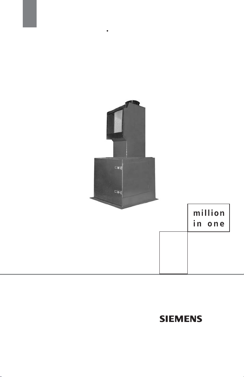
Instruction Manual May 2008
milltronics
A SERIES
Page 2

Safety Guidelines: Warning notices must be observed to ensure personal safety as well as that of
others, and to protect the product and the connected equipment. These warning notices are
accompanied by a clarification of the level of caution to be observed.
Qualified Personnel: This device/system may only be set up and operated in conjunction with this
manual. Qualified personnel are only authorized to install and operate this equipment in accordance with
established safety practices and standards.
Unit Repair and Excluded Liability:
• The user is responsible for all changes and repairs made to the device by the user or the user’s
agent.
• All new components are to be provided by Siemens Milltronics Process Instruments Inc.
• Restrict repair to faulty components only.
• Do not reuse faulty components.
Warning: This product can only function properly and safely if it is correctly transported, stored,
installed, set up, operated, and maintained.
This product is intended for use in industrial areas. Operation of this equipment in a residential area
may cause interference to several frequency based communications.
Note: Always use product in accordance with specifications.
Copyright Siemens Milltronics Process
Disclaimer of Liability
Instruments Inc. 2008. All Rights Reserved
This document is available in bound version and in
electronic version. We encourage users to purchase
authorized bound manuals, or to view electronic versions
as designed and authored by Siemens Milltronics Process
Instruments Inc. Siemens Milltronics Process Instruments
Inc. will not be responsible for the contents of partial or
whole reproductions of either bound or electronic
versions.
While we have verified the contents of this
manual for agreement with the
instrumentation described, variations
remain possible. Thus we cannot
guarantee full agreement. The contents of
this manual are regularly reviewed and
corrections are included in subsequent
editions. We welcome all suggestions for
improvement.
Technical data subject to change.
MILLTRONICS®is a registered trademark of Siemens Milltronics Process Instruments Inc.
Contact SMPI Technical Publications European Authorized Representative
at the following address:
Technical Publications Siemens AG
Siemens Milltronics Process Instruments Inc. Industry Sector
1954 Technology Drive, P.O. Box 4225 76181 Karlsruhe
Peterborough, Ontario, Canada, K9J 7B1 Deutschland
Email: [email protected]
• For a selection of Siemens Milltronics level measurement manuals, go to:
www. siemens.com/processautomation. Under Process Instrumentation, select
Measurement
• For a selection of Siemens Milltronics weighing manuals, go to:
www. siemens.com/processautomation. Under Weighing Technology, select
Weighing Systems
© Siemens Milltronics Process Instruments Inc. 2008
and then go to the manual archive listed under the product family.
and then go to the manual archive listed under the product family.
Level
Continuous
Page 3

Table of Contents
Milltronics A Series Solids Flowmeters ........................................................................ 1
The Manual............................................................................................................................................... 1
Specifications ......................................................................................................................3
Installation ........................................................................................................................... 4
Location ..................................................................................................................................................... 4
Applications .........................................................................................................................5
Materials ................................................................................................................................................... 5
Material Feed ........................................................................................................................................... 5
Maintenance ........................................................................................................................6
Checks ..............................................................................................................................................6
Unit Repair and Excluded Liability ............................................................................................6
A-40 Outline & Mounting....................................................................................................................... 7
A-300 Outline & Mounting .................................................................................................................... 8
i
Page 4

ii
Page 5
Milltronics A Series Solids Flowmeters
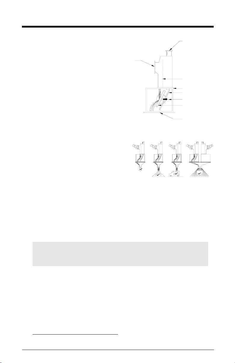
Milltronics A Series solids flowmeters
are heavy-duty low- to mediumcapacity flowmeters for light density
powders conveyed by aerated gravity
material
infeed
dust collector
port
conveyors.
The A-40 flowmeter is equipped with an
ILE-37 sensing head and is suitable for
material flowrates up to 40 t/h (44
STPH). The A-300 flowmeter, with an
ILE-61 sensing head, is suitable for up to
300 t/h (330 STPH).
flowguide
housing (cabinet)
baffle
impact force
sensing plate
material discharge
The flowmeter sensing head LVDT
output signal is processed by the integrator (ordered separately) to:
• monitor material flow
• maintain accurate material inventory
• provide batch control for process or
loadout purposes
1
• control the ratio of materials in
1
continuous blending processes
The following components complete each Milltronics A Series flowmeter system.
• A series flowmeter housing (cabinet) and flowguide
• ILE-37 or ILE-61 sensing head (ordered separately)
• stainless steel sensing plate (ordered separately)
• electronic flowmeter integrator (ordered separately)
AB
A+B
The Manual
Note: This product is intended for use in industrial areas. Operation of this
equipment in a residential area may cause interference to several frequency
based communications.
This instruction manual covers the installation, operation and maintenance of the A
Series solids flowmeter.
Please refer to this manual for proper installation and operation of any component of the
system to which the A Series is being applied. Adhering to the installation and operating
procedures will ensure a quick, trouble-free installation and allow for the maximum
accuracy and reliability of your weighing system. Because the A Series is used in
conjunction with an integrator and sensing head, refer to the instruction manuals for
those devices as well.
1.
additional equipment required
7ML19985CV01 Milltronics A Series – INSTRUCTION MANUAL Page 1
Page 6

If you have any questions, comments, or suggestions about the manual contents, please
email us at [email protected]
For the complete library of Siemens Milltronics manuals,
go to www.siemens.com/processautomation
.
.
Page 2 Milltronics A Series– INSTRUCTION MANUAL 7ML19985CV01
Page 7

Specifications
Model
• A-40
•A-300
Product
• fine powder up to 3 mm (0.13")
Product Temperature
• -40 to 232 °C (-40 to 450 °F)
• -40 to 400 °C (-40 to 750 °F) (optional)
Ambient Temperature
• -40 to 60 °C (-40 to 140 °F)
Accuracy
• "1 %, 33 to 100 % of design capacity; extended accuracy range with linearization
function of integrator
Repeatability
•± 0.2 %
Capacity Range
• A-40: 0.2 to 40 t/h (0.2 to 44 STPH)
• A-300: 20 to 300 t/h (22 to 330 STPH)
Construction
• painted mild steel flowguide and sensing plate housing and AISI 304 (1.4306) stainless
steel sensing plate
• optional special materials and coatings for flowguide and sensing plate
• A-40: ILE-37
• A-300: ILE-61 sensing head, cast aluminum with fibreglass cover
1
sensing head (base mount), cast aluminum with fibreglass cover
Approvals
• CSA certified, general purpose (sensing head)
2
•CE
Options
• 304 (1.4301) or 316 (1.4404) stainless steel housing and flowguide assembly
• PTFE or Abrasion Resistant flowguide lining
• CSA Class I, Groups C and D; Class II, Groups E, F, and G (sensing head)
1.
The ILE-37 is available in side mount version (supported by the housing) or base
mount version (supported separately from the housing).
2.
EMC performance available upon request.
7ML19985CV01 Milltronics A Series – INSTRUCTION MANUAL Page 3
Page 8
Installation
Location
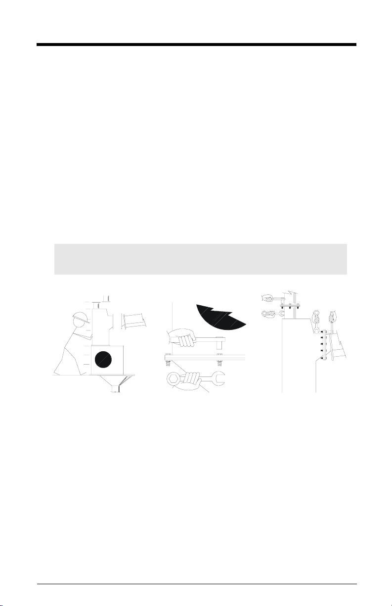
Install Milltronics A Series solids flowmeter in an area that is suitable for the system
approval rating. Maintain sufficient clearance to permit: opening the housing door for
sensing plate access and removing the sensing head rear cover for calibration purposes.
1. Position the flowmeter into the desired location.
2. If necessary, shim the housing base to level.
3. Fasten the housing discharge to the downstream material chute.
4. Fasten the flowguide to the conveyor/flowguide transition chute.
5. Fasten the dust collector port to the dust collector pipe.
6. Refer ILE-37 or ILE-61 sensing head instruction manuals for sensing head
installation, levelling, sensing plate installation, and integrator interconnection
instructions.
7. Tune the dust collector port air volume to match that of the aerated gravity conveyor
exhaust port, and the downstream dust collector port.
Note: Ensure sufficient mechanical support is provided for the flowmeter and
chutework.
Page 4 Milltronics A Series– INSTRUCTION MANUAL 7ML19985CV01
Page 9
Applications
Note: For best performance and limited maintenance requirements, keep in mind
material compatibility and flow patterns.
Materials
Material characteristics for best results:
• low cohesion (flows well in aerated state, similar to a liquid)
• low adhesion (does not stick to surfaces)
• low abrasion (will not wear out chutes, flowguide or sensing plate)
• low causticity (will not damage internal flowmeter components)
Materials such as powdered alumina, limestone, and finished cement are ideally suited
to aerated gravity conveyor and A Series flowmeter applications.
Material Feed
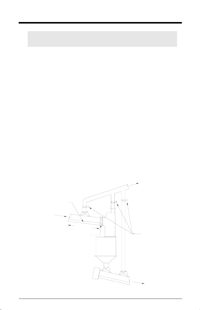
The constant velocity and non-pulsing material discharge of an aerated gravity conveyor
are considered ideal for accurate, repeatable performance. The conveyor discharge/
flowmeter infeed transition chute should be as short as possible and at the same angle
as the flowmeter flowguide. Fabricate the transition chute so the conveyor aeration
chamber is not vented directly into the flowmeter.
Make sure the the flowmeter discharge chute is large enough so material cannot back up
into the flowmeter housing.
to dust collector
aeration chamber
material in
2 m (6 ft.) min.
transition by
customer
7ML19985CV01 Milltronics A Series – INSTRUCTION MANUAL Page 5
tuning gates
material out
Page 10
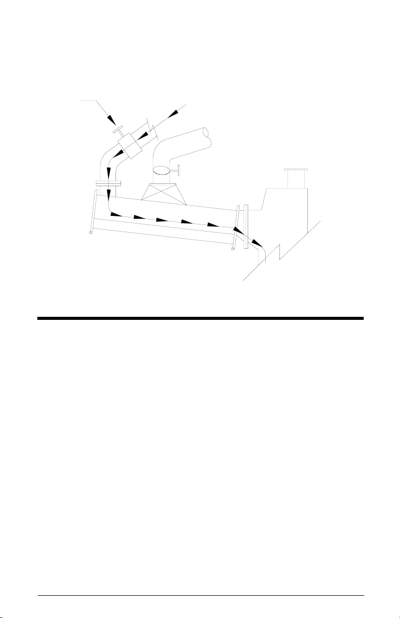
A mechanical or automatic modulating valve may be required for:
• material flowrate control
• pulsing conveyor infeed damping
If a modulating valve is used, reverse the direction of material flow after the valve and
before the material enters the aerated gravity conveyor.
modulating
valve
material
flow
Maintenance
Checks
If material sticks to the sensing plate, incorporate a program to ensure that the
impingement area remains clean. If sticking persists, contact your Siemens Milltronics
representative.
Check for wearing of the sensing plate. If wear is excessive, contact your Siemens
Milltronics representative.
Unit Repair and Excluded Liability
All changes and repairs must be done by qualified personnel and applicable safety
regulations must be followed. Please note the following:
• The user is responsible for all changes and repairs made to the device.
• All new components must be provided by Siemens Milltronics Process
Instruments Inc.
• Restrict repair to faulty components only
• Do not re-use faulty components.
Page 6 Milltronics A Series– INSTRUCTION MANUAL 7ML19985CV01
Page 11
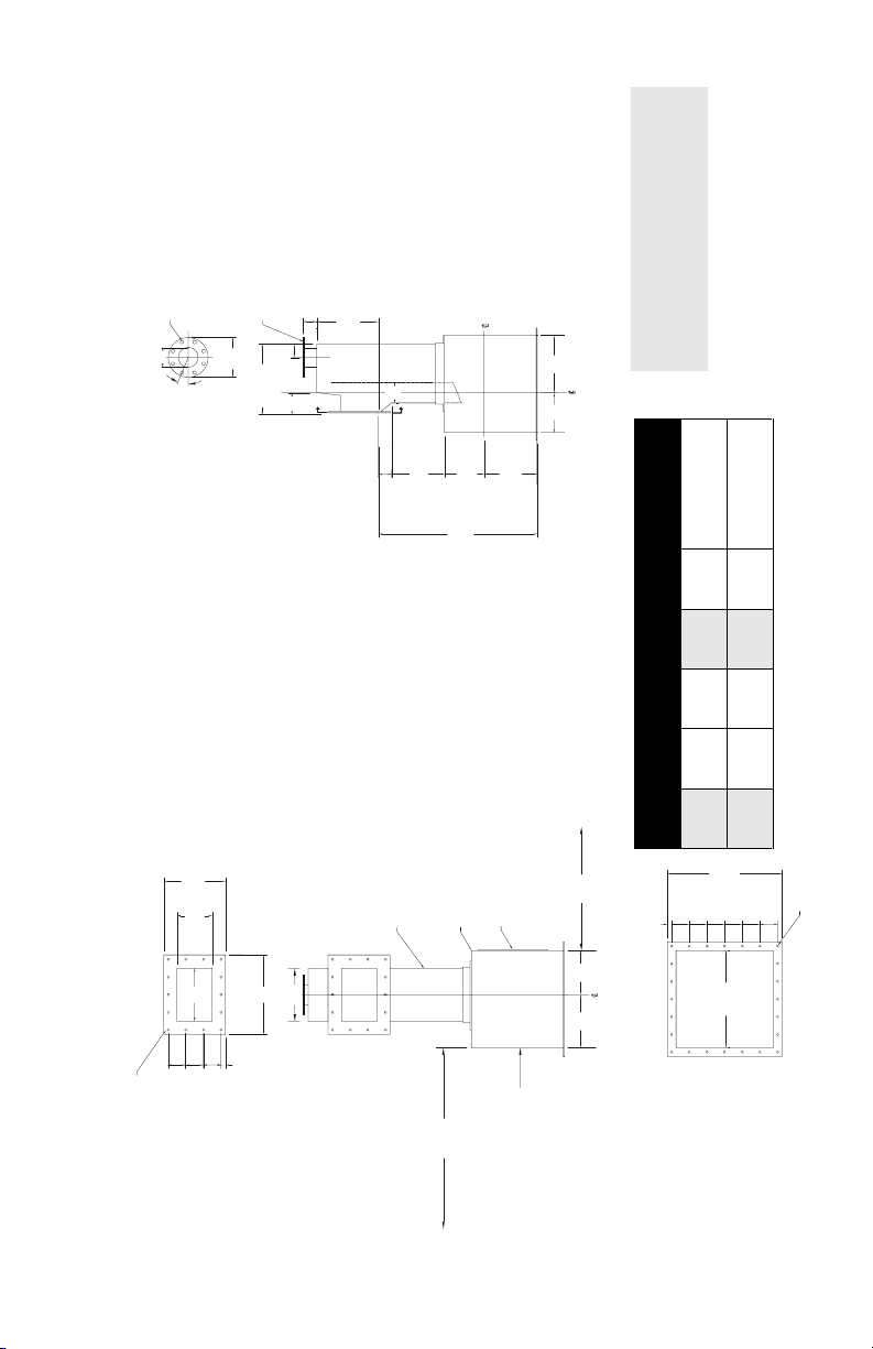
A-40 Outline & Mounting
8 holes, 19 mm (0.75") dia.
(4")
102 mm
191 mm (7.5") bolt circle dia.
(9")
229 mm
22.5°
(14")
356 mm
(8")
203 mm
76 mm (3")
dust collector port
(3")
76 mm
(16")
406 mm
127 mm (5")
(14")
356 mm
A
B
A
305 mm
76 mm (3")
flowguide
sensing head
Notes:
1. Mild steel or stainless construction.
2. Sensing head support should be rigid and
independent of housing.
(13")
330 mm
(9")
229 mm
flowguide
(9")
(12")
229 mm
(12")
305 mm
)
3
Max. flow
(36")
914 mm
(28")
711 mm
minimum allowance for
sensing plate installation
hinged, gasket door
housing (cabinet)
@ 50 pcf (0.8 t/m
12 20 t/h (22 STPH)
14 40 t/h (44 STPH)
(14")
(18")
356 mm
457 mm
(3")
(4")
76 mm
102 mm
(8")
(12")
203 mm
305 mm
1
Size A B C D
102 mm
25 mm (1")
2
(26")
660 mm
(4")
11 mm (0.44") dia, thru
holes 24 places
11 mm (0.44") dia, thru
VIEW ’A - A’
holes qty D
(10")
to suit sensing head
access and bolt holes
254 mm
flowguide
(12")
305 mm
(22")
559 mm
A
102 mm (4")
102 mm (4")
102 mm (4")
A
C
25 mm (1")
(24")
610 mm
minimum allowance for
sensing head installation
Page 12
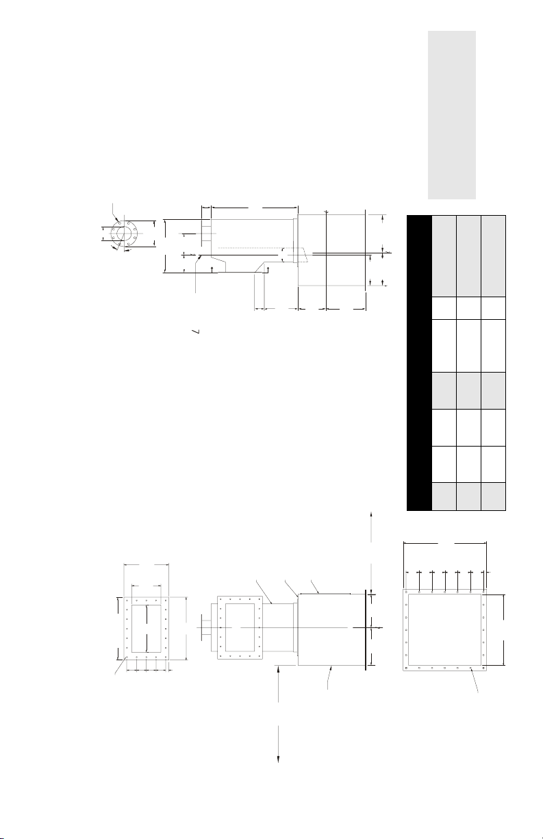
Notes:
1. Mild steel or stainless construction.
2. Sensing head support should be rigid
80 t/h (88 STPH)
16
(4 @ 3.5")
4 @ 90 mm
(16.5")
419 mm
(5")
127 mm
(10")
254 mm
1
and independent of housing.
160 t/h (176 STPH)
16
(4 @ 4.5")
4 @ 114 mm
(20.5")
521 mm
(6")
152 mm
(14")
356 mm
2
300 t/h (330 STPH)
20
(6 @ 4")
6 @ 102 mm
(26.5")
673 mm
(7")
178 mm
(20")
508 mm
3
8 holes, 22 (0.88) dia.
241 (9.5) B.C. dia.
(6.36")
162 mm
(11")
279 mm
(22.7")
577 mm
22.5°
c
(7.5")
A
191 mm
flowguide
c
B
A
356 mm
102 mm (4")
sensing head
c
406 mm
(13")
330 mm
(11.5")
292 mm
(14")
(16.5")
419 mm
)
3
(16")
sensing head shaft
c
(14")
Max. Flow
356 mm
@ 50 pcf (0.8 t/m
Size A B C D E
A-300 Outline & Mounting
(34.5")
876 mm
(18.5")
470 mm
(12")
305 mm
A
C
D spacing
View ’A - A’
102 mm (4")
holes qty E
32 mm (1.25")
102 mm (4")
102 mm (4")
102 mm (4")
flowguide
housing (cabinet)
hinged, gasket door
(41")
1041 mm
(35")
889 mm
minimum allowance for
sensing plate installation
356 mm
406 mm
137mm (5.38")
137mm (5.38")
137mm (5.38")
133mm (5.25")
137mm (5.38")
133mm (5.25")
(14")
c
(16")
(30")
762 mm SQ
11 mm (0.44") dia., thru
head and cover removal
minimum allowance for sensing
access and bolt holes
to suit sensing head
14 mm (0.56") dia, thru
holes 24 places
Page 13

Notes
Page 14

Notes
Page 15

Page 16

www.siemens.com/processautomation
Siemens Milltronics Process Instruments Inc.
1954Technology Drive, P.O. Box 4225
Peterborough, ON, Canada K9J 7B1
Tel: (705) 745-2431 Fax: (705) 741-0466
Email: [email protected]
Siemens Milltronics Process Instruments Inc. 2008
Subject to change without prior notice
*7ml19985cv01*
Printed in Canada
Rev. 1.2
 Loading...