

Page 1
s
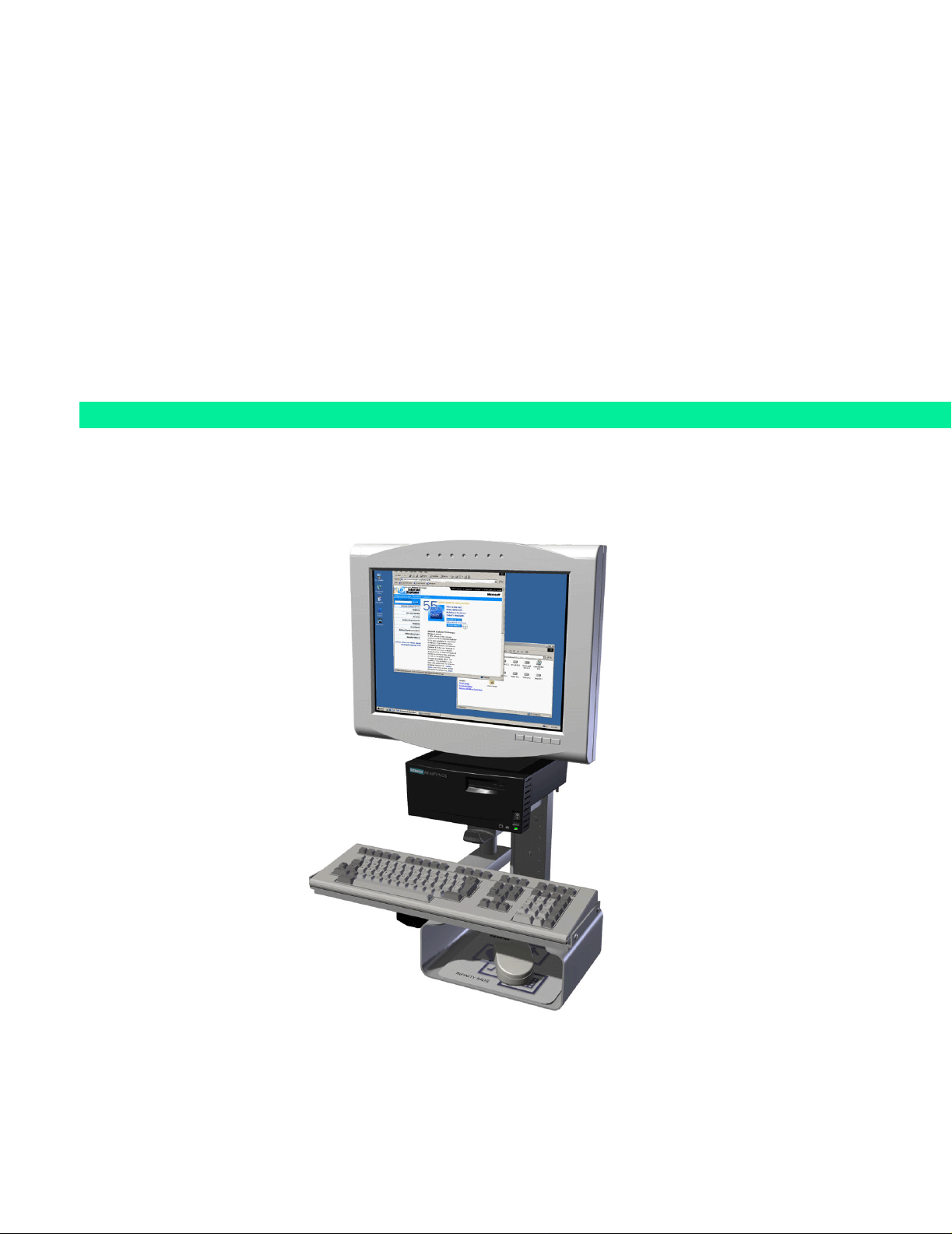
INFINITY Medside Data Station
Windows 2000 Version
Service Manual
ASK-T962-03-7600
EM Guidelines, 1997-04-02
Page 2

ADVISORY
This document corresponds to the version/revision level effective at the time of system delivery. Revisions to
hardcopy documentation are not automatically distributed.
The installation and service of equipment described herein is to be performed by qualified personnel who are
employed by Siemens or one of its affiliates or who are otherwise authorized by Siemens or one of its affiliates
to provide such services.
Assemblers and other persons who are not employed by or otherwise directly affiliated with or authorized by
Siemens or one of its affiliates are directed to contact one of the local offices of Siemens or one of its affiliates
before attempting installation or service procedures.
Page 3

Medside Data Station Field Service Manual
Table of Contents
1 Introduction . . . . . . . . . . . . . . . . . . . . . . . . . . . . . . . . . . . . . . . . . . . . . . . . . . . . . . . . . . . .1
2 Troubleshooting . . . . . . . . . . . . . . . . . . . . . . . . . . . . . . . . . . . . . . . . . . . . . . . . . . . . . . . . .1
2.1 Power Problem . . . . . . . . . . . . . . . . . . . . . . . . . . . . . . . . . . . . . . . . . . . . . . . . . . . . . .1
2.1.1 No Response when power On/Off switch toggled ON . . . . . . . . . . . . . . . . . . .1
2.1.2 Power On/Off Piezo Tone Fails to Sound . . . . . . . . . . . . . . . . . . . . . . . . . . . . .2
2.1.3 Power-Up Sequence Fails to Complete Properly . . . . . . . . . . . . . . . . . . . . . . . 2
2.1.4 No Video display . . . . . . . . . . . . . . . . . . . . . . . . . . . . . . . . . . . . . . . . . . . . . . . .3
2.1.5 MDS Fails to boot properly . . . . . . . . . . . . . . . . . . . . . . . . . . . . . . . . . . . . . . . .3
2.2 BIOS Setup . . . . . . . . . . . . . . . . . . . . . . . . . . . . . . . . . . . . . . . . . . . . . . . . . . . . . . . . .3
3 MDS Installation Overview . . . . . . . . . . . . . . . . . . . . . . . . . . . . . . . . . . . . . . . . . . . . . . . . .7
4 MDS Hardware Installation . . . . . . . . . . . . . . . . . . . . . . . . . . . . . . . . . . . . . . . . . . . . . . . . 7
4.1 MDS Mounting Arm Installation . . . . . . . . . . . . . . . . . . . . . . . . . . . . . . . . . . . . . . . . 7
4.2 MDS Table Top Installation . . . . . . . . . . . . . . . . . . . . . . . . . . . . . . . . . . . . . . . . . . . . .8
5 Monitor Installation . . . . . . . . . . . . . . . . . . . . . . . . . . . . . . . . . . . . . . . . . . . . . . . . . . . . . . .8
5.1 CRT (Art. No. 57 35 894 E5310) . . . . . . . . . . . . . . . . . . . . . . . . . . . . . . . . . . . . . . . . .9
5.2 Flat Screen Display (Art. No. 59 55 567 E531U) . . . . . . . . . . . . . . . . . . . . . . . . . . . .10
5.3 Locally Supplied Monitor . . . . . . . . . . . . . . . . . . . . . . . . . . . . . . . . . . . . . . . . . . . . .12
6 Keyboard, Mouse . . . . . . . . . . . . . . . . . . . . . . . . . . . . . . . . . . . . . . . . . . . . . . . . . . . . . . .12
6.1 Wall Mount . . . . . . . . . . . . . . . . . . . . . . . . . . . . . . . . . . . . . . . . . . . . . . . . . . . . . . . .12
6.2 Table Top . . . . . . . . . . . . . . . . . . . . . . . . . . . . . . . . . . . . . . . . . . . . . . . . . . . . . . . . .12
7 Connecting Devices . . . . . . . . . . . . . . . . . . . . . . . . . . . . . . . . . . . . . . . . . . . . . . . . . . . . .12
8 Reinstallation Windows 2000 Operating Systems and Installing Optional Drivers . . . . .1 4
8.1 Laptop Configuration . . . . . . . . . . . . . . . . . . . . . . . . . . . . . . . . . . . . . . . . . . . . . . . .14
8.1.1 TCP/IP Setup . . . . . . . . . . . . . . . . . . . . . . . . . . . . . . . . . . . . . . . . . . . . . . . . . .15
8.1.2 CDROM Share Configuration . . . . . . . . . . . . . . . . . . . . . . . . . . . . . . . . . . . . .16
8.1.3 Install MDS Utility . . . . . . . . . . . . . . . . . . . . . . . . . . . . . . . . . . . . . . . . . . . . . .18
ASK-T962-03-7600 Siemens Medical Solutions, EM-PCS Danvers i
MDS2K_sm.fm/04-02/Sulak
Page 4

Field Service Manual Medsi de Data Station
8.2 MDS to Service Laptop Interface . . . . . . . . . . . . . . . . . . . . . . . . . . . . . . . . . . . . . . .19
8.3 Launch MDS Utility . . . . . . . . . . . . . . . . . . . . . . . . . . . . . . . . . . . . . . . . . . . . . . . . . .20
8.4 MDS Network Boot. . . . . . . . . . . . . . . . . . . . . . . . . . . . . . . . . . . . . . . . . . . . . . . . . .21
8.5 Mapping MDS. . . . . . . . . . . . . . . . . . . . . . . . . . . . . . . . . . . . . . . . . . . . . . . . . . . . . .21
8.6 Install Windows 2000 Image. . . . . . . . . . . . . . . . . . . . . . . . . . . . . . . . . . . . . . . . . . .22
9 Phoenix BIOS Phlash . . . . . . . . . . . . . . . . . . . . . . . . . . . . . . . . . . . . . . . . . . . . . . . . . . . .3 2
9.1 Hardware Setup . . . . . . . . . . . . . . . . . . . . . . . . . . . . . . . . . . . . . . . . . . . . . . . . . . . .32
9.2 Software Setup . . . . . . . . . . . . . . . . . . . . . . . . . . . . . . . . . . . . . . . . . . . . . . . . . . . . .32
9.2.1 CDROM Setup Procedure . . . . . . . . . . . . . . . . . . . . . . . . . . . . . . . . . . . . . . . .32
9.2.2 Download Setup Procedure . . . . . . . . . . . . . . . . . . . . . . . . . . . . . . . . . . . . . .33
9.3 MDS Hard Drive Phlash Procedure . . . . . . . . . . . . . . . . . . . . . . . . . . . . . . . . . . . . .34
10 Replacement Procedures . . . . . . . . . . . . . . . . . . . . . . . . . . . . . . . . . . . . . . . . . . . . . . . . .36
10.1Opening MDS . . . . . . . . . . . . . . . . . . . . . . . . . . . . . . . . . . . . . . . . . . . . . . . . . . . . . .36
10.2Replacing Battery . . . . . . . . . . . . . . . . . . . . . . . . . . . . . . . . . . . . . . . . . . . . . . . . . .38
10.3Replacing Hard Drive . . . . . . . . . . . . . . . . . . . . . . . . . . . . . . . . . . . . . . . . . . . . . . . .39
10.4Replacing Memory / Daughterboard . . . . . . . . . . . . . . . . . . . . . . . . . . . . . . . . . . . . .4 0
10.5Closing MDS . . . . . . . . . . . . . . . . . . . . . . . . . . . . . . . . . . . . . . . . . . . . . . . . . . . . . . .41
11 Functional Check. . . . . . . . . . . . . . . . . . . . . . . . . . . . . . . . . . . . . . . . . . . . . . . . . . . . . . . .42
12 Leakage Current Test . . . . . . . . . . . . . . . . . . . . . . . . . . . . . . . . . . . . . . . . . . . . . . . . . . . .43
Appendix A: Spare Parts . . . . . . . . . . . . . . . . . . . . . . . . . . . . . . . . . . . . . . . . . . . . . . . . . . . 47
Appendix B: BIOS Messages . . . . . . . . . . . . . . . . . . . . . . . . . . . . . . . . . . . . . . . . . . . . . . . .51
Appendix C: POST Error Codes . . . . . . . . . . . . . . . . . . . . . . . . . . . . . . . . . . . . . . . . . . . . . . 55
ii Siemens Medical Solutions, EM-PCS, Danvers ASK-T962-03-7600
MDS2K_sm.fm/04-02/Sulak
Page 5

Medside Data Station Field Service Manual
1Introduction In keeping with the Service Strategy for the Medside Data Station (MDS),
this Service Manual provides the necessary information required to
troubleshoot and service a Windows 2000 based MDS. The MDS is
powered by an AC/DC power adapter, and can be placed on a desktop or
attached to a wall bracket. Control of all Medside Data Station functions is
done by means of a keyboard and a mouse. (It is recommended that the
keyboard and mouse be purchased through SIEMENS, to avoid any
possible incompatibility problems). The display screen has a 1280 x 1024
resolution capabilities which enables the user to display and run
applications such as I
NFINITY
TM
Explorer and Webview.
For the purpose of clarification, special text in this Service Manual is
described below:
Bold Characters text that is to be typed in by the User.
Character a space required between typed characters.
^
Italic Characters a selection that is required by the User.
2Troubleshooting If the Medside Data Station should fail to respond properly, use the
procedures below to aid in identifying and remedying the problem.
2.1 Power Problem
2.1.1 No Response when power On/Off switch toggled ON
Table 2-1 Power-On Problem
Conditions Possible Cause(s) Troubleshooting and Remedial Action
MDS connected
directly to Power
Adapter; Power
Adapter LED not
illuminated
MDS directly
connected to Power
Adapter; Power
Power source.
Power Adap te r
malfunction.
MDS Malfunction.
Power Adap te r
malfunction.
MDS Power Switch
Adapter LED On, MDS
charger LED not
MDS malfunction.
illuminated.
Refer to Table 2-1 to troubleshoot Power-On problems.
1) Assure Power Adapter is connected to an active
hospital power source.
2) If problem persists, disconnect power adapter from
MDS and measure voltage between Power Adapter
output pins.
•If voltage q 11.6 VDC or Q 13.8 VDC, replace
Power Adapter.
• If voltage = 11.6 to 13.8 VDC, contact TSS in
Solna or Danvers.
1) Disconnect power adapter from MDS and measure
voltage between Power Adapter output pins.
• If voltage q 11.6 VDC or Q 13.8 VDC, replace
power adapter.
• If voltage = 11.6 to 13.8 VDC, contact TSS in Solna
or Danvers.
MDS directly
connected to Power
Adapter; MDS Charger
LED illuminated. No
MDS Power Switch
malfunction.
MDS malfunction.
1) Switch MDS Power to On.
2) If MDS fails to Power-up, contact TSS in Solna or
Danvers.
Power On LED.
ASK-T962-03-7600 Siemens Medical Solutions, EM-PCS Danvers 1
MDS2K_sm.fm/04-02/Sulak
Page 6

Field Service Manual Medsi de Data Station
Table 2-1 Power-On Problem (Continued)
Conditions Possible Cause(s) Troubleshooting and Remedial Action
MDS not connected to
A/C Power Adapter;
Power switch On,
Internal UPS Battery
discharged.
Replace Internal battery.
Power LED not
illuminated.
MDS malfunction
2.1.2 Power On/Off Piezo Tone Fails to Sound.
Table 2-2 Power-off Alarm Malfunction
1) Connect MDS to A/C Power Adapter.
2) Switch MDS Power switch to On and verify that
battery charger LED illuminates.
Note: If Power On LED fails to illuminate, contact
TSS in Solna or Danvers.
3) If battery charger LED fails to illuminate, leave
power adapter connected to MDS for i 1hr.
4) After 1 hr. disconnect MDS from Power Adapter
and switch MDS Power On/Off switch Off, and then
On.
• If Power LED is green, reconnect MDS to Power
Adapter and leave MDS connected an additional
8 hours to charge internal battery.
• If Power LED is not green, replace Internal
batteries.
5) If problem still persists, contact TSS in Solna or
Danvers.
Symptom(s) Possible Cause(s) Troubleshooting and Remedial Action
Piezo tone fails to
sound when MDS
Speaker.
MDS malfunction.
Contact TSS in Solna or Danvers.
powered On, if MDS
loses power, or when
MDS is powered-Off.
2.1.3 Power-Up Sequence Fails to Complete Properly
Table 2-3 Power-up Process Malfunction
Symptom(s) Possible Cause(s) Troubleshooting and Remedial Action
Power inputs OK, but
MDS fails to complete
boot up.
BIOS failure.
Software program
corrupted.
Hard Drive failure.
MDS malfunction.
1) If MDS displays error message proceed to
“Appendix B: BIOS Messages” on page 51, and
“Appendix C: POST Error Codes” on page 55 to
identify failure.
2) Check BIOS configuration according to Section 2.2.
3) If BIOS configuration OK, reinstall Windows
according to Section 8 starting on page 14.
4) If problem still persists, contact TSS in Solna or
Danvers.
TM
2000
2 Siemens Medical Solutions, EM-PCS, Danvers ASK-T962-03-7600
MDS2K_sm.fm/04-02/Sulak
Page 7
Medside Data Station Field Service Manual
aaaa
SW 2
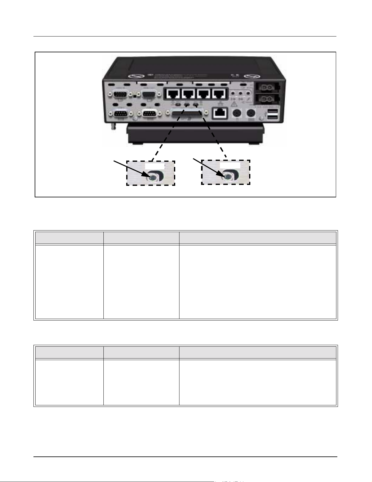
Figure 2-1 MDS switch settings
2.1.4 No Video display Table 2-4 Video malfunction
Symptom(s) Possible Cause(s) Troubleshooting and Remedial Action
MDS power LED On.
No video on LCD/CRT
Display.
2.1.5 MDS Fails to boot properly Table 2-5 Power On/MDS Malfunction
Cable problem.
No power to Display.
Bad display.
Video switch set
incorrectly.
MDS malfunction.
ssss
SW 1
1) Check both ends of video cable and ensure cable is
connected.
2) If prob lem persists, verify power source to display.
3) If problem persists, switch out display with a known
good display.
4) If problem persists, verify MDS video switch position
(see a in Figure 2-1) at rear of MDS is set to right.
5) If problem still persists, contact TSS Danvers/Solna.
Symptom(s) Possible Cause(s) Troubleshooting and Remedial Action
MDS power LED On.
MDS Resets after
successful boot.
Watchdog timer switch
set incorrectly.
BIOS problem.
MDS malfunction
1) Verify Watchdog timer switch position (see s in
Figure 2-1) at rear of MDS is set to left.
2) If problem persists, check BIOS configuration as
described in Section 2.2.
3) If problem still persists, contact TSS Danvers/Solna.
2.2 BIOS Setup The MDS is configured at the factory for default settings that provide
proper operation. Use the following procedure to check MDS BIOS setup,
if MDS does not boot to Windows 2000 logon screen. Changing BIOS
settings is not necessary on a new MDS, unless system failure occurs.
1) Switch MDS Power On/Off switch to On.
ASK-T962-03-7600 Siemens Medical Solutions, EM-PCS Danvers 3
MDS2K_sm.fm/04-02/Sulak
Page 8
Field Service Manual Medsi de Data Station
a
s
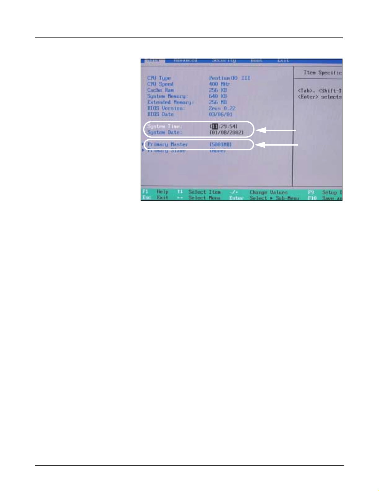
Figure 2-2 Main screen
2) Press and hold F2 key to gain access to PhoenixBIOS Setup Utility.
3) Press F9 key, then press <Enter> to load default BIOS configuration
settings.
4) Press F10 key, then press <Enter> to save configuration settings.
Note: After <Enter> key is pressed, MDS will reboot.
5) Verify that MDS boots to Windows 2000 logon screen. If MDS does
not boot to Window 2000 logon screen, proceed to step 6.
6) Toggle MDS On/Off power switch Off, and then On to reboot MDS.
7) Press and hold F2 key to gain access to PhoenixBIOS Setup Utility.
8) Enter correct date/time (a in Figure 2-2) for clinical site, using arrow/
number keys.
9) Verify correct “Primary Master” settings as shown in (s in Figure 2-2).
Note: If Primary Master is incorrect, use up/down arrow keys to
select Primary Master, and then press <Enter> key.
4 Siemens Medical Solutions, EM-PCS, Danvers ASK-T962-03-7600
MDS2K_sm.fm/04-02/Sulak
Page 9
Medside Data Station Field Service Manual
a
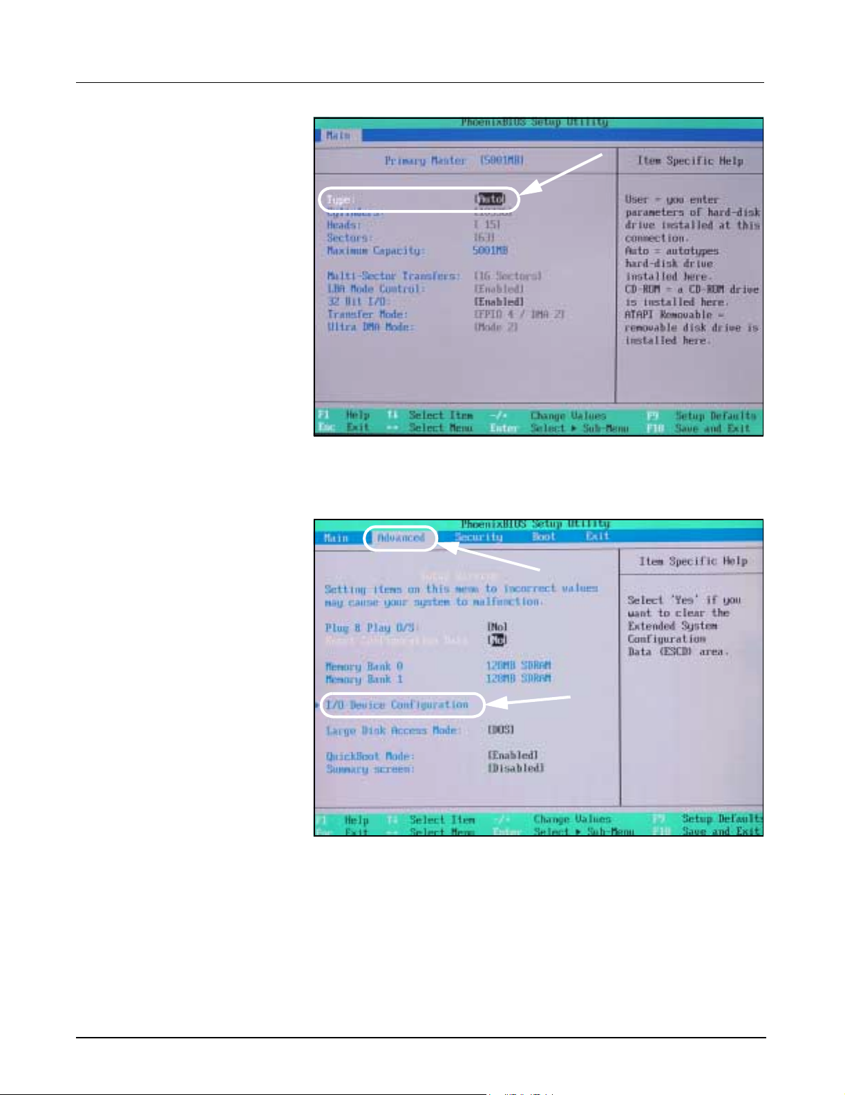
Figure 2-3 Hard drive settings
10) Use +/- keys to select type to Auto (a in Figure 2-3).
11) Press ESC key to get back to “Main” tab .
a
s
Figure 2-4 Advanced settings
12) Use left/right arrow keys to select “Advanced” tab (a in Figure 2-4).
13) Verify correct “Advanced” settings as shown in Figure 2-4.
Note: If changes need to be made use up/down arrow keys.
14) Use up/down arrow keys to select I/O Configuration (s in Figure 2-4),
and then press <Enter> key.
ASK-T962-03-7600 Siemens Medical Solutions, EM-PCS Danvers 5
MDS2K_sm.fm/04-02/Sulak
Page 10
Field Service Manual Medsi de Data Station
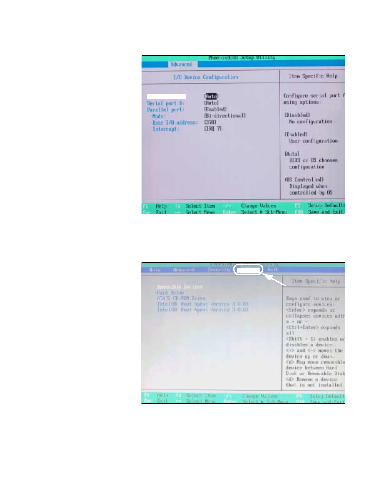
Serial port A:
Figure 2-5 I/O Device configuration
15) Verify correct “I/O Device Configuration” settings as shown in Figure 2-5.
Note: Use left/right arrow and +/- keys to make changes.
16) Press ESC key to return to main menu.
Boot
a
Figure 2-6 Boot settings
17) Use up/down arrow keys to select “Boot” tab (a in Figure 2-6).
18) Verify correct “Boot” order as shown in Figure 2-6.
Note: Use left/right arrow and +/- keys to make changes.
19) Press F10 key, and then press <Enter> to save configuration settings.
Note: After <Enter> key is pressed, MDS reboots.
6 Siemens Medical Solutions, EM-PCS, Danvers ASK-T962-03-7600
MDS2K_sm.fm/04-02/Sulak
Page 11
Medside Data Station Field Service Manual
20) Verify that Windows 2000 logon screen appears.
21) If MDS fails to boot to Windows 2000 logon screen, proceed to
Section 9 to Phlash BIOS.
22) If Phlash BIOS setup procedure does not boot to Windows 2000
logon screen, proceed to Section 8 and re-install Windows 2000. If
problem still exists, contact TSS in Danvers/Solna.
3 MDS Installation
Overview
4 MDS Hardware
Installation
4.1 MDS Mounting Arm Installation
Install the Medside Data Station in a location that has good air circulation
and is reasonably free from dust, extreme temperatures, and humidity.
The MDS and the devices for the MDS are not intended for use in the
same room with magnetic resonance equipment. Make sure a hospital
grade power outlet and ethernet terminal (if connecting to a LAN) are
located near MDS.
Caution:
Do not place anything on top or bottom of Medside Data Station
that can obstruct air flow to the ventilation holes on each side.
Do not place any liquid containers on MDS, to avoid possibility
of a liquid spill damaging MDS.
Do either a or b as appropriate:
a If installing an MDS on mounting arm, go on to Section 4.1.
b If installing an MDS on table top, go on to Section 4.2.
Refer to front cover for an illustration of a complete wall mount setup of a
Medside Data Station (Flat screen display shown).
1) Secure mount to wall (see instructions included with mounting arm).
!
aaaa
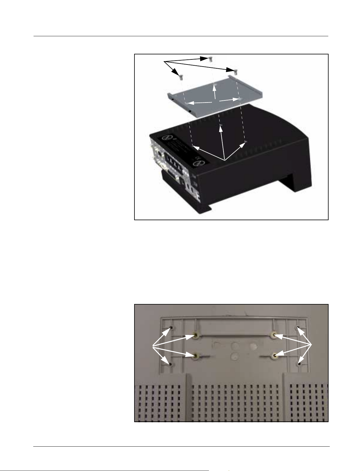
Figure 4-1 Mounting plate
2) Align mounting plate (a in Figure 4-1) on bottom of MDS to slots (a
in Figure 4-2) on left side of mounting bracket.
ASK-T962-03-7600 Siemens Medical Solutions, EM-PCS Danvers 7
MDS2K_sm.fm/04-02/Sulak
ssss
Page 12
Field Service Manual Medsi de Data Station
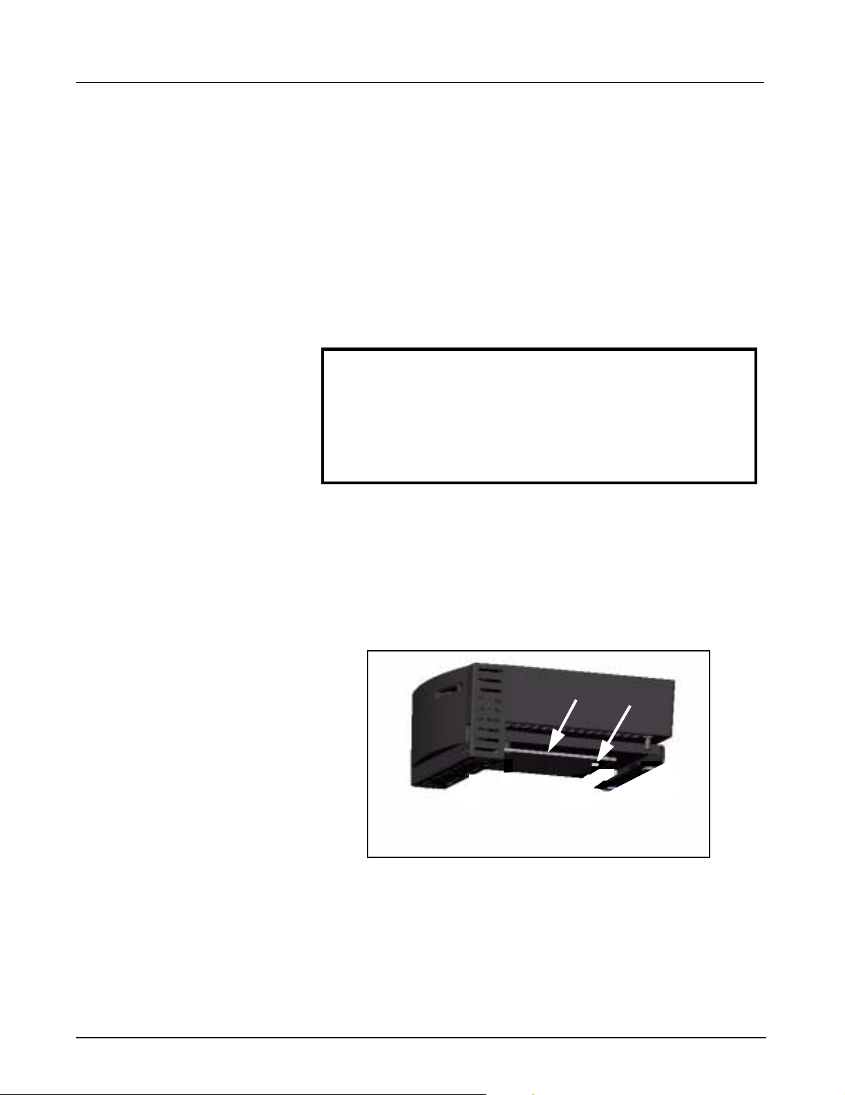
4.2 MDS Table Top Installation
aaaa
Figure 4-2 Mounting bracket
3) Pull down and hold spring loaded locking pin (s in Figure 4-2), and
slide in MDS to align hole on mounting plate (s in Figure 4-1) with
locking pin.
4) Release locking pin to secure mounting plate to mounting bracket.
Note: The locking pin snaps into place when properly installed.
5) Proceed to Section 5.
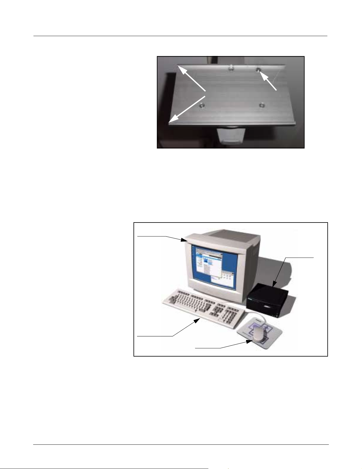
Monitor
ssss
Medside
Data
Station
Keyboard
Mouse
Figure 4-3 Medside Data Station (table top configuration)
1) Set MDS on flat clean surface, and within close proximity of monitor,
keyboard, and mouse. See Figure 4-3.
2) Proceed to Section 5.
5 Monitor Installa tio n Do either a, b, or c as appropriate:
a If installing optional CRT to wall mount, go to Section 5.1.
b If installing optional Flat Screen to Medside Data Station, go to
Section 5.2.
c If installing locally supplied monitor, go to Section 5.3.
8 Siemens Medical Solutions, EM-PCS, Danvers ASK-T962-03-7600
MDS2K_sm.fm/04-02/Sulak
Page 13
Medside Data Station Field Service Manual
5.1 CRT (Art. No. 57 35 894 E5310)
The same type of mounting bracket used to mount the Medside Data
Station is used to mount the CRT monitor.
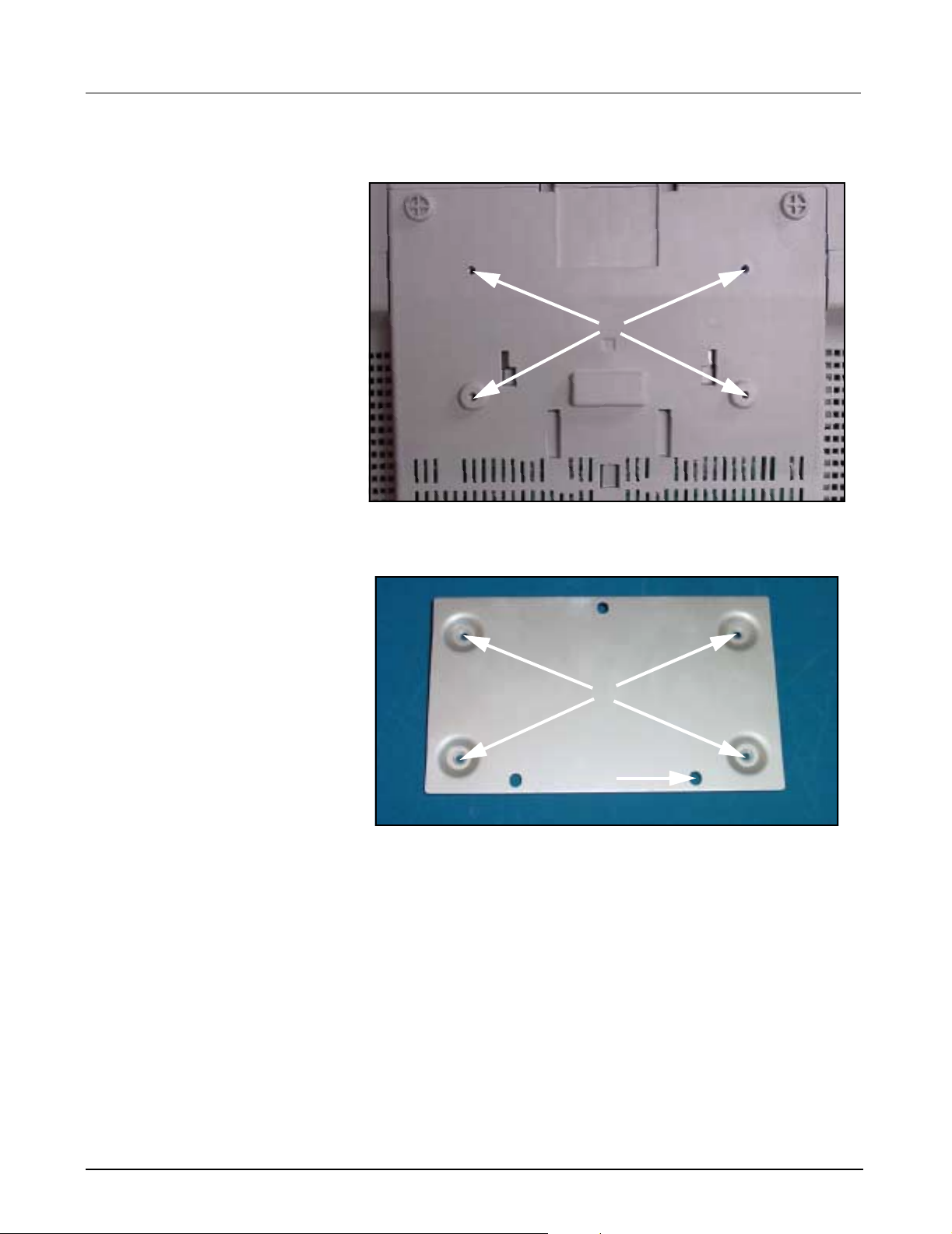
aaaa
Figure 5-1 Monitor (bottom view)
1) Set Monitor upside down on clean surface.
aaaa
ssss
Figure 5-2 Mounting plate
2) Align clearance holes on mounting plate (a in Figure 5-2) to threaded
holes on bottom of monitor (a in Figure 5-1), orientated so that raised
area around holes on plate are against bottom of monitor.
Note: This creates a gap so that the plate can easily slide into
mounting bracket. Make sure the drill hole (s in Figure 5-2) is
towards back of monitor. This hole is used for a locking pin from the
mounting bracket.
3) Insert and tighten 4 Phillips-head screws (supplied).
4) Set monitor upright with mounting plate aligned to slots on left side of
mounting bracket (see Figure 4-2 on page 8), and slide monitor into
bracket so that hole on mounting plate aligns with locking pin.
5) Secure with locking pin. See step 3 in Section 4.1.
6) Proceed to Section 6.
ASK-T962-03-7600 Siemens Medical Solutions, EM-PCS Danvers 9
MDS2K_sm.fm/04-02/Sulak
Page 14
Field Service Manual Medsi de Data Station
5.2 Flat Screen Display
(Art. No. 59 55 567
dddd
E531U)
aaaa
ssss
Figure 5-3 MDS with mounting bracket
1) Set MDS upright on flat surface.
2) Remove and discard three plastic plugs from mounting holes on top
of MDS.
3) Align mounting bracket screw holes (a in Figure 5-3) to screw holes
on top of MDS (s in Figure 5-3).
Note: Mounting bracket and screws ship with flat screen display.
4) Insert and tighten 3 Phillips-head screws (supplied, d in Figure 5-3).
aaaa
aaaa
Figure 5-4 Flat Screen Display (rear view)
10 Siemens Medical Solutions, EM-PCS, Danvers ASK-T962-03-7600
MDS2K_sm.fm/04-02/Sulak
Page 15
Medside Data Station Field Service Manual
aaaaaaaa
ssss
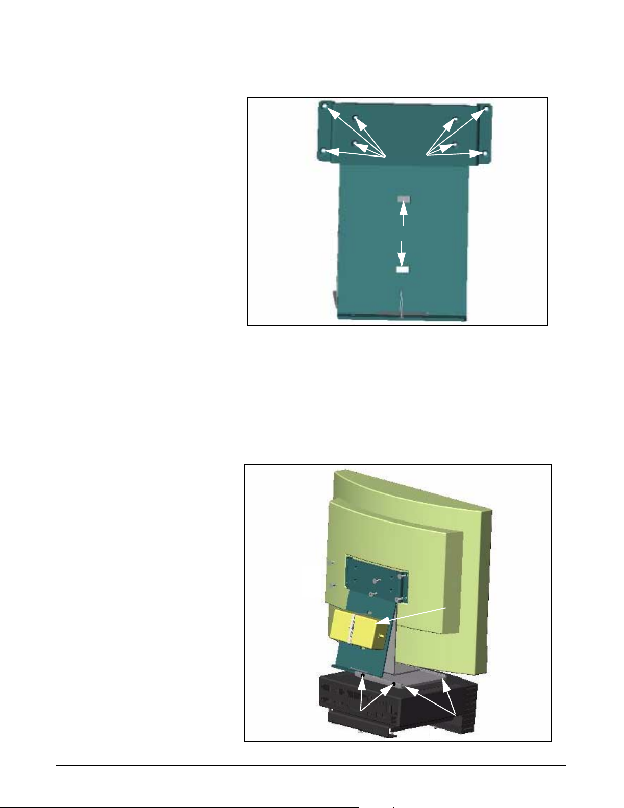
Figure 5-5 Flat Screen Support Mount
5) Place flat screen display face down on clean surface. See Figure 5-4
on page 10.
6) Align 8 support mount clearance holes (a in Figure 5-5) to threaded
holes on back of flat screen display (a in Figure 5-4).
7) Insert and tighten 8 Phillips-head screws (supplied).
8) Insert 1 cable tie (supplied) through back of each slot (s in Figure 5-5)
to enable power supply to be secured to support mount.
aaaa
dddd
Figure 5-6 Flat Screen Display mounted to MDS
ASK-T962-03-7600 Siemens Medical Solutions, EM-PCS Danvers 11
MDS2K_sm.fm/04-02/Sulak
ssss
Page 16

Field Service Manual Medsi de Data Station
9) Set power supply (a in Figure 5-6) between both slots on support
mount, and tighten cable tie to secure supply to mount.
10) Set flat screen display upright with bottom of support mount aligned
to slots on mounting bracket (installed in step 2 and 3 above), and
slide mount into bracket (s in Figure 5-6 on page 11), so that mount
is positioned in center.
11) Insert and tighten 2 Phillips-head screws (supplied, d in Figure 5-6)
on rear of mounting bracket to secure flat screen display in bracket.
12) Proceed to Section 6.
5.3 Locally Supplied Monitor
Refer to Installation instructions that were provided with monitor.
1) Set monitor on secure flat surface in close proximity to MDS.
2) Proceed to Section 6.
6 Keyboard, Mouse Do either a or b as appropriate:
a If installing keyboard and mouse to wall mount, go to Section 6.1.
b If installing keyboard and mouse on table top, go to Section 6.2.
6.1 Wall Mount 1) Set keyboard on shelf (refer to illustration on front cover), and slide in
side clamps to secure keyboard to shelf.
2) Set mouse on shelf (refer to illustration on front cover).
3) Proceed to Section 7.
6.2 Table Top 1) Set keyboard and mouse in close proximity to MDS. See Figure 4-3
on page 8.
2) Proceed to Section 7.
7 Connecti ng Devices 1) Insert and tighten 15 pin video cable from monitor into video out
connector (s in Figure 7-1 on page 13) on rear of MDS.
2) Plug in Keyboard cable into keyboard connector (J in Figure 7-1) on
rear of MDS.
3) Plug in mouse cable into mouse connector (H in Figure 7-1) on rear of
MDS.
4) Plug power cord from monitor into hospital grade outlet. (If using flat
screen monitor connect power cable from 12V DC power supply into
back of monitor, and then plug in power cord from power adapter into
hospital grade outlet).
5) Plug in power connector from MDS AC power adapter into Power In
connector (j in Figure 7-1) on back of Medside Data Statio n, and
then plug in power cord from AC adapter into hospital grade outlet.
6) Proceed to Section 11, Functional Check - Power Circuits and Startup.
12 Siemens Medical Solutions, EM-PCS, Danvers ASK-T962-03-7600
MDS2K_sm.fm/04-02/Sulak
Page 17
Medside Data Station Field Service Manual
aaaas
llll
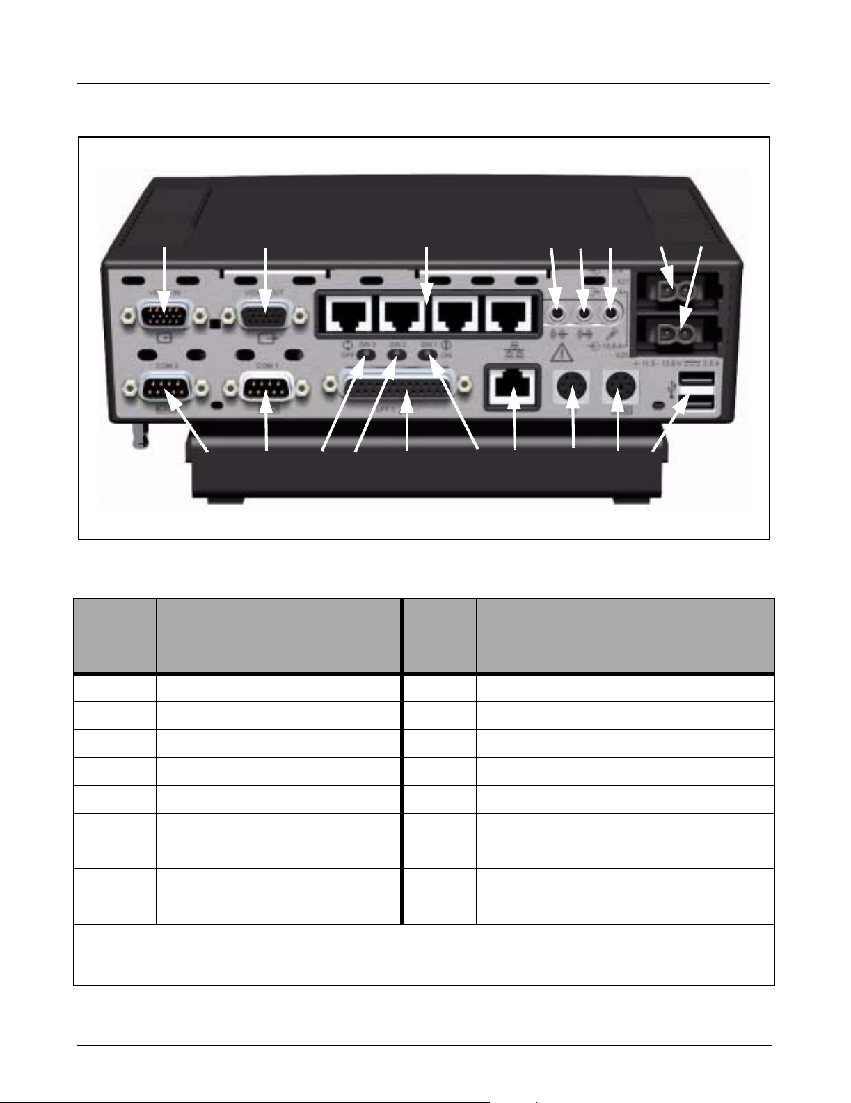
Figure 7-1 MDS (rear view)
Table 3: MDS Part Description
Item
Number
Description
GGGG
ffffg
HHHH
sd
ss
;;;;
AAAA
SSSS
d
dd
DDDD
Item
Numbe
r
FFFF
Description
g
gg
hhhh
KKKKJJJJ
jjjj
kkkk
1 VIDEO IN / OPTIONAL COM 3/4 10 COM 1
2 VIDEO OUT 11 BOOT ROM SELECT (default, switch to right)
3 *ETHERNET HUB 12 VIDEO OVERRIDE (default, switch to right)
4 AUDIO OUT 13 PARALLEL PORT
5 AUDIO IN 14 PIEZO OVERRIDE (default, switch to right)
6 MICROPHONE 15 MAIN ETHERNET (auto-negotiating)
7POWER IN 16MOUSE
8 POWER (future use) 17 KEYBOARD
9 COM 2 18 USB
* Ethernet Hub will not auto-negotiate to a 10Mbs device. If a 10Mbs device is connected to the Ethernet Hub
all devices must be manually set to 10Mbs operation. If All ports are occupied by 100Mbs devices, no manual
settings are required. Consult your local IT department regarding manual settings of 10Mbs devices.
ASK-T962-03-7600 Siemens Medical Solutions, EM-PCS Danvers 13
MDS2K_sm.fm/04-02/Sulak
Page 18
Field Service Manual Medsi de Data Station
8 Reinstallation of
Windows 2000
Operating Systems
and Installing
Optional Drivers
Windows 2000
Reinstallation
Optional Hardware MDS Optional Hardware includes a Teac
This section explains how to reinstall Windows 2000 and also references
how to install Optional Hardware Drivers onto a Medside Data Station hard
drive.
Note: Windows 2000 reinstallation should not be required on a
new MDS. The factory installs Windows 2000 on the MDS prior to
shipment.
In addition to these instructions, the following Hardware and Software is
required:
• Siemens Service Laptop meeting minimum Hardware
requirements as specified by Med QM document ARTD-
001.719.06.04.02 (V01) M4 or greater.
• RJ45 crossover cable.
• MDS Software Recovery CDROM (shipped with MDS).
Windows 2000 reinstallation requires making a network boot connection
between an MDS RJ-45 network port, and a Windows 95/98 Laptop/PC
RJ-45 network port, and then transferring the Windows 2000 image from
the Laptop/PC CDROM drive to the MDS Hard Drive.
TM
CDROM Drive, BackpackTM
NFINITY
TM
Optical Mouse. Refer to “Loading
TM
Medside Data Station Reference Manual
CDRW Drive, and Microsoft
Software” section in I
for Teac CDROM drive and Backpack CDRW drive operation.
An Optical Mouse driver CDROM is shipped with each Optical Mouse.
This driver must be loaded through a network connection to the MDS.
Contact local IT department for network connection configuration.
8.1 Laptop Configuration Setup the Service laptop as follows to allow network connectivity between
a Laptop CDROM drive and an MDS Hard drive.
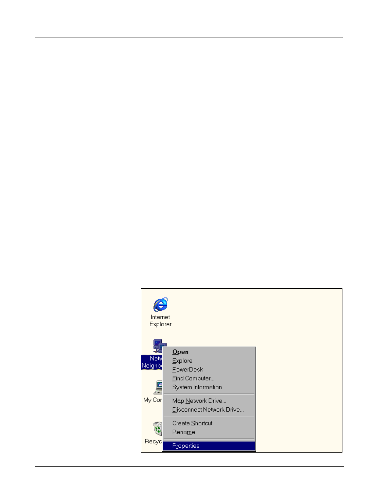
Figure 8-1 Windows Main Menu
14 Siemens Medical Solutions, EM-PCS, Danvers ASK-T962-03-7600
MDS2K_sm.fm/04-02/Sulak
Page 19
Medside Data Station Field Service Manual
8.1.1 TCP/IP Setup 1) Boot Service Laptop to Windows
2) Right-click on Network Neighborhood icon (see Figure 4-1 on page 7)
and click on Properties.
TM
95/98 screen.
Figure 8-2 Network Window
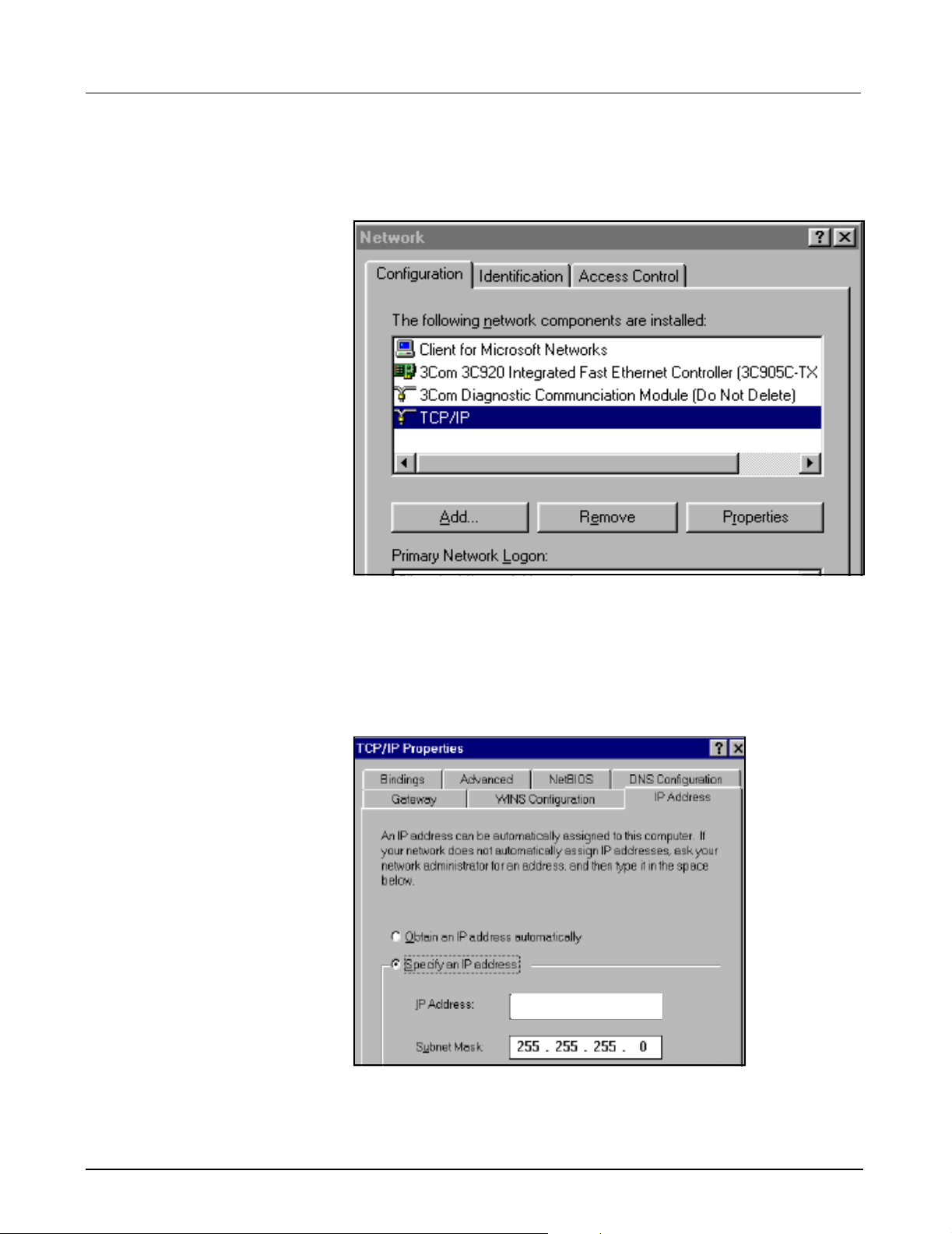
3) At “Network” window (see Figure 8-2) click on Configuration Tab,
scroll down to Laptop TCP/IP Ethernet Adapter, and select Properties.
Note: TCP/IP Ethernet Adapter name is unique according to
specific adapter used on laptop. Refer to Service Laptop Ethernet
Adapter vendor document for specific name.
Laptop Settings
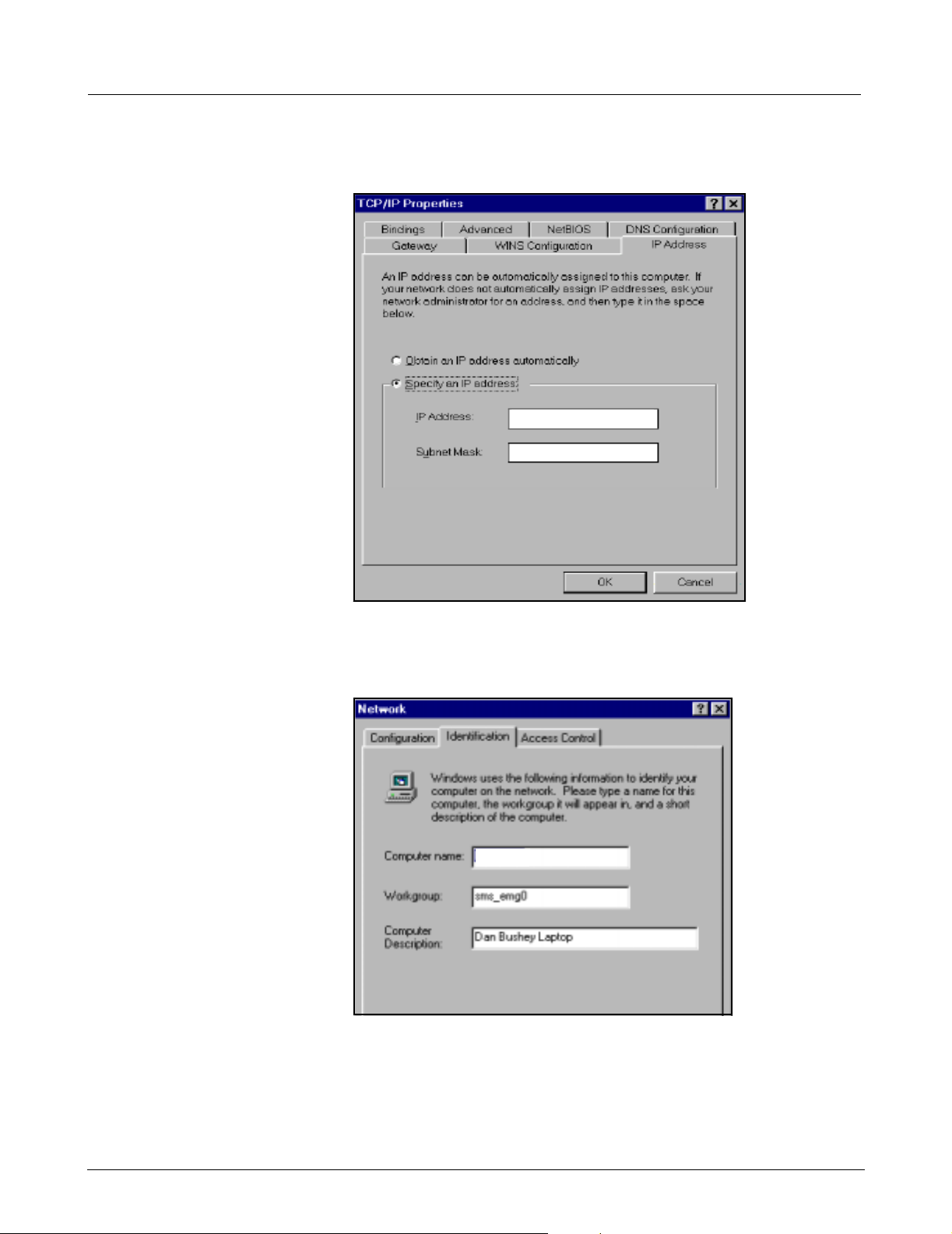
Figure 8-3 TCP/IP Window
4) Copy “IP Address” to the following
line:_____________________________
ASK-T962-03-7600 Siemens Medical Solutions, EM-PCS Danvers 15
MDS2K_sm.fm/04-02/Sulak
Page 20
Field Service Manual Medsi de Data Station
Note: IP Address is needed to reconfigure the service laptop back to
its original configuration, after completing Windows 2000 reinstallation.
192. 168. 0. 1
255. 255. 255. 0
Figure 8-4 TCP/IP Window
5) Type new IP address 192.168.0.1 as shown in Figure 8-4, then click
on OK button.
Laptop Settings
Figure 8-5 Network window
6) At “Network” window (see Figure 8-5) click on Identification Tab.
7) Copy Computer Name to the following line:_______________________
8.1.2 CDROM Share Configuration
The service laptop CDROM must be set up for file sharing. Complete the
following section to configure service laptop CDROM for file sharing.
16 Siemens Medical Solutions, EM-PCS, Danvers ASK-T962-03-7600
MDS2K_sm.fm/04-02/Sulak
Page 21

Medside Data Station Field Service Manual
1) Select Start and scroll to Programs, and then Windows Explorer .
Figure 8-6 Windows Explorer
2) At “Exploring” window, right-click on CDROM icon and select Sharing
from drop down menu (see Figure 8-6).
Note: Steps 2-4 can also be used to set up file sharing of laptop
hard drive (eg.“C”drive, “D” drive) and laptop floppy drive (“A”
drive) by selecting that drive in step 2 and providing a unique userprovided share name in step 3.
a
a
aa
Figure 8-7 Properties Window
3) At “Properties” window, click on Shared As button (a in Figure 8-7),
type CDROM in “Share Name:” box, click on Apply, then click OK.
ASK-T962-03-7600 Siemens Medical Solutions, EM-PCS Danvers 17
MDS2K_sm.fm/04-02/Sulak
Page 22

Field Service Manual Medsi de Data Station
a
Figure 8-8 Windows Explorer
4) Verify that there is a hand shown below the CDROM icon (see a in
Figure 8-8).
8.1.3 Install MDS Utility The MDS requires the use of a software utility to make a low level connection between a MDS and a Service Laptop. This utility is also used to transfer data between the two devices. Install the MDS software Utility as follows:
1) Insert MDS Recovery CDROM (shipped with MDS) into Service
laptop CDROM Drive.
2) At Service laptop Windows screen, select Start and scroll to
Programs, then Windows Explorer.
a
Figure 8-9 Explorer Window
3) Click on CDROM icon (a in Figure 8-9) in left pane of “Explorer”
window.
4) Double click on Tftpboot directory in right pane of Explorer window.
5) Double-click on Remoteboot.exe file in right pane of Explorer window.
18 Siemens Medical Solutions, EM-PCS, Danvers ASK-T962-03-7600
MDS2K_sm.fm/04-02/Sulak
Page 23

Medside Data Station Field Service Manual
Figure 8-10 Win Zip Extractor Window
6) Click on Unzip button.
Note: Files are extracted to tftpboot folder on the laptop “C” drive.
Once files have been extracted, the Win Zip Self-Extractor
windows appear, indicating 25 file(s) unzipped successfully (see
Figure 8-10).
7) Click on OK, then Close in “Win Zip Self-Extractor” windows.
8) Close “Windows Explorer” window.
a
a
aa
Figure 8-11 MDS, Laptop Hardware Connection
8.2 MDS to Service
Laptop Interface
1) Connect Crossover Cable from Laptop Network Interface Card
Ethernet Port to MDS Main Ethernet Port (a in Figure 8-11).
Note: Ensure MDS is not connected to Hospital Network.
2) Connect MDS Power Adapter, Keyboard, Mouse, and Monitor
according to MDS Hardware Installation Instructions. Refer to Doc.
No. T951-XX-7600 (shipped with MDS).
ASK-T962-03-7600 Siemens Medical Solutions, EM-PCS Danvers 19
MDS2K_sm.fm/04-02/Sulak
Page 24

Field Service Manual Medsi de Data Station
a
a
aa
d
d
dd
s
s
ss
Figure 8-12 Windows Explorer
8.3 Launch MDS Utility 1) At Laptop Windows screen, select Start and scroll to Programs, and
then to Windows Explorer.
2) Double-click on C drive icon (a in Figure 8-12) in left pane of window.
3) Click on tftpboot folder (s in Figure 8-12) in left pane.
Note: Verify power On/Off switch on MDS is Off.
4) Double-click on MDS Remote Boot icon (d in Figure 8-12) in right
pane.
Finished - MDS Remote Boot
TFTPD - Trivial File Transfer Daemon
s
s
ss
DCHP/Bootp Server 1.6.5
a
a
aa
d
d
dd
Figure 8-13 Window TFTPD
20 Siemens Medical Solutions, EM-PCS, Danvers ASK-T962-03-7600
MDS2K_sm.fm/04-02/Sulak
Page 25

Medside Data Station Field Service Manual
5) Verify “Finished - MDS Remote Boot” window (a in Figure 8-13)
opens, then “TFTPD - Trivial File Transfer Daemon” window (s in
Figure 8-13) opens, then DHCP/Bootp Server 1.6.5 window (d in
Figure 8-13) opens. If these windows are not displayed repeat steps 2-
4 above.
Note: DHCP/Boottp Server 1.6.5 window may open minimized. If
window is not displayed on Main screen,(d in Figure 8-13) check
to see if program is in Windows Task bar at bottom of screen.
aaaassssdddd
Figure 8-14 Setup Utility Window
8.4 MDS Network Boot 1) Switch Power On/Off switch on MDS to On.
2) Press and hold F2 key to enter BIOS setup.
3) At PhoenixBIOS Setup Utility window, use MDS keyboard left/right
arrow keys to Select Boot Tab (a in Figure 8-14).
4) Use MDS keyboard Up/Down arrows to Select +Hard Drive (s in
Figure 8-14).
5) Hold down on Shift key, and momentarily press ! key.
6) Verify that an exclamation point ! appears to the left of +Hard Drive
(d in Figure 8-14).
7) Press MDS keyboard F10 key.
8) Press <Enter> to save and exit.
Figure 8-15 MDS Service Menu
9) Verify MDS reboots to “MDS Service Menu” (see Figure 8-15).
10) Use MDS keyboard Up/Down arrows, if necessary, to Select Boot to
network login, and then press <Enter>.
ASK-T962-03-7600 Siemens Medical Solutions, EM-PCS Danvers 21
MDS2K_sm.fm/04-02/Sulak
Page 26

Field Service Manual Medsi de Data Station
8.5 Mapping MDS After pressing <Enter>, the MDS Utility establishes a network link
between the Service Laptop and the MDS. Once this link has been
established, the A:\> prompt appears at bottom of screen.
Figure 8-16 Map M.D.S. to CD ROM drive
The text after the A:\ prompt displays an example of how to map the MDS
to a Service Laptop CDROM Drive (see Figure 8-16).
8.6 Install Windows 2000
Image
11) After the A:\> prompt, type net
use^x:^^\\computername\shared
^
drivename, and then press <Enter>.
Note: Computer name = name noted in step 7 of Section 8.1.1,
and shared drive = name of drive typed in step 3 of Section 8.1.2.
12) At message “Type your user name, or press ENTER if it is
ADMINISTRATOR:”, press <Enter>.
13) At message “Type your password:”, press <Enter>.
14) At message “Please confirm your password, so that a password list
may be created:”, press <Enter>.
15) At A:\> prompt, type x: and then press <Enter>.
Caution:
TM
Windows
2000 reinstallation must be performed only in cases
where the MDS hard drive has been replaced with a new blank
hard drive, or if Windows 2000 is corrupted and reinstallation is a
final troubleshooting procedure. All data (non-Windows 2000)
files must be backed up before proceeding with reinstallation, as
the MDS hard drive is erased (formatted) during the reinstallation
process.
22 Siemens Medical Solutions, EM-PCS, Danvers ASK-T962-03-7600
MDS2K_sm.fm/04-02/Sulak
Page 27

Medside Data Station Field Service Manual
Figure 8-17 Norton Ghost menu
1) At X:\> prompt type ghost, and then press <Enter>.
2) After Norton
Norton Ghost Utility.
TM
Ghost screen appears, click on OK to begin using
Figure 8-18 Utility Window
3) At Norton Ghost Utility window, select L
4) Click on From Image, and then press <Enter>.
XXX_XXXX.GHO
ocal Q Disk Q From Image.
a
Figure 8-19 Image Folder (Image file)
5) At “File name to load image from” window, click on xxx_xxxx.GHO
(see a in Figure 8-19).
ASK-T962-03-7600 Siemens Medical Solutions, EM-PCS Danvers 23
MDS2K_sm.fm/04-02/Sulak
Page 28

Field Service Manual Medsi de Data Station
Figure 8-20 Drive Number Window
6) At “Select local destination drive by clicking on the drive number”
window, click on OK button.
Figure 8-21 Destination Drive Window
7) At “Destination Drive Details” window, click on OK button.
24 Siemens Medical Solutions, EM-PCS, Danvers ASK-T962-03-7600
MDS2K_sm.fm/04-02/Sulak
Page 29

Medside Data Station Field Service Manual
Figure 8-22 Image Transfer Window
8) At “Question” window, click on Yes to proceed with disk load.
Note: Ghost image is transferred from the Service Laptop CDROM
drive to the MDS hard drive. Once Ghost image has been
transferred “Clone Complete” window appears. See Figure 8-23
on page 25.
Continue
Figure 8-23 Clone Window
9) At “Clone Complete” window, click on Continue to return to Ghost
Main Utility page.
Quit
Figure 8-24 Main Window
ASK-T962-03-7600 Siemens Medical Solutions, EM-PCS Danvers 25
MDS2K_sm.fm/04-02/Sulak
Page 30

Field Service Manual Medsi de Data Station
Yes
Figure 8-25 Quit Symantec Ghost Window
10) At “Quit Symantec Ghost” window, click on Yes to return to X:\>
prompt.
11) At MDS keyboard, press and hold Ctrl
+Alt +Delete keys to reboot
MDS.
12) Press and hold MDS F2 key to enter PhoenixBIOS Setup Utility.
13) Complete steps 2 and 3 in Section 8.4 (removing exclamation point
from left side of “+Hard Drive”) to enable MDS hard drive boot.
Press MDS keyboard F10 key, and then press <Enter> to save and exit.
Figure 8-26 Windows 2000 Setup Screen
14) Verify MDS bots to Windows 2000 Setup Wizard.
15) C li ck on Next.
16) At Operating System License Agreement screen, click on button
beside “I accept this agrement”, then click on Next.
26 Siemens Medical Solutions, EM-PCS, Danvers ASK-T962-03-7600
MDS2K_sm.fm/04-02/Sulak
Page 31

Medside Data Station Field Service Manual
Figure 8-27 Windows 2000 Setup screen
17) At “Regional Settings Window” screen (see Figure 8-27) click on
Customize and set System and Keyboard settings for local regional
parameters, then click Next.
Figure 8-28 Personalize screen
18) At “Personalize Your Software” screen (see Figure 8-28), type in your
name and Organization and click on Next.
ASK-T962-03-7600 Siemens Medical Solutions, EM-PCS Danvers 27
MDS2K_sm.fm/04-02/Sulak
Page 32

Field Service Manual Medsi de Data Station
Figure 8-29 Computer Name and Administrator Password screen
19) At “Computer Name and Administrator” screen (see Figure 8-29),
type in Computer name in “Computer name” box.
20) Type Administrator password in “Administrator password” box. Then
re-type Administrator password in “Confir m password” box and click
on Next.
Figure 8-30 Local Date and Time screen
21) At “Date and Time Settings” screen (see Figure 8-30), set Local Date,
Time and Time Zone for local region parameters. If appropriate for this
region, check box next to “Automatically adjust for daylight savings
time”.
22) C li ck on Next.
28 Siemens Medical Solutions, EM-PCS, Danvers ASK-T962-03-7600
MDS2K_sm.fm/04-02/Sulak
Page 33

Medside Data Station Field Service Manual
Figure 8-31 Network Settings screen
23) If configuring MDS for a network, select Custom Settings, th en clic k
on Next and follow instructions to set up MDS for this network as
specified by the Hospital IT Administrator. Otherwise, select Typical
Settings and click on Next.
Figure 8-32 Workgroup/Domain screen
24) At “Workgroup or Domain” screen, (see Figure 8-32) set up this
computer as specified by Hospital IT Administrator, then click Next.
ASK-T962-03-7600 Siemens Medical Solutions, EM-PCS Danvers 29
MDS2K_sm.fm/04-02/Sulak
Page 34

Field Service Manual Medsi de Data Station
Figure 8-33 Completing Setup screen
25) At “Completing the Windows Setup Wizard” screen, (see Figure 8-
33) click on Finish.
Figure 8-34 Network Identification screen
26) Verify MDS reboots to “Network Identification Wizard” window (see
Figure 8-34) .
27) C li ck on Next.
30 Siemens Medical Solutions, EM-PCS, Danvers ASK-T962-03-7600
MDS2K_sm.fm/04-02/Sulak
Page 35

Medside Data Station Field Service Manual
Figure 8-35 Network User screen
28) Type in this computers User Name and Password information (see
Figure 8-35) and click on Next.
Figure 8-36 Complete Network Identification screen
29) At “Completing the Network Identification Wizard” window, (see
Figure 8-36) click on Finish.
30) Verify that correct language appears on Windows 2000 Workstation
main screen.
ASK-T962-03-7600 Siemens Medical Solutions, EM-PCS Danvers 31
MDS2K_sm.fm/04-02/Sulak
Page 36

Field Service Manual Medsi de Data Station
9 Phoenix BIOS Phlash Each MDS is shipped with a default BIOS (installed at the factory).
Phlashing BIOS is necessary only if current MDS BIOS is not operating
correctly or if an updated version is needed to correct MDS system
failures. If original BIOS is not operating correctly, complete Sect ion 2.2
before Phlashing BIOS. If Section 2.2 fails to correct problem, Phlash BIOS
as described below.
BIOS Phlash files are distributed in 4 formats:
• Existing Phlash files on MDS hard drive.
• Phlash files on MDS Software CDROM (shipped with each MDS).
• Upgrade Phlash files ordered from factory.
• Upgrade Phlash files downloaded from EM location on MED-TD
site (www-td.med.siemens.de).
Setup MDS to phlash the MDS BIOS as described in Section 9.1 and
Section 9.2 below.
a
a
aa
Figure 9-1 MDS (rear view)
9.1 Hardware Setup Verify that BIOS switch (see a in insert in Figure 9-1) on rear of MDS is
set to right.
9.2 Software Setup Copy Phlash software to MDS hard drive according to Section 9.2.1 for
CDROM or Section 9.2.2 below, if downloading from laptop.
9.2.1 CDROM Setup Procedure
32 Siemens Medical Solutions, EM-PCS, Danvers ASK-T962-03-7600
Use this procedure to load Phlash software from MDS CDROM (shipped
with MDS), or Phlash Upgrades distributed on CDROM (ordered from
Factory).
1) Insert MDS CDROM into Service Laptop.
2) Configure service laptop for network boot according to Section 8.1
through Section 8.4.
MDS2K_sm.fm/04-02/Sulak
Page 37

Medside Data Station Field Service Manual
a
a
aa
s
s
ss
d
d
dd
f
f
ff
Figure 9-2 DOS Window
3) At DOS A:> Phlash prompt, type C: (a in Figure 9-2) and press
<Enter>.
9.2.2 Download Setup Procedure
4) At DOS C:> prompt, t ype md
<Enter>.
Note: If message “A subdirectory or file phlash already exists”
appears, press <Enter>.
5) At DOS C:> prompt, type x: (d in Figure 9-2) and press <Enter>.
6) At DOS X:> prompt, type copy
and press <Enter>.
Note: If message “Overwrite C:\PHLASH\PHLASH.Exe (Yes/NO/All)
appears, type A and press <Enter>.
7) Verify that the following files scroll up the screen:
• Phlash\Phlash.exe
• Phlash\Zeus_XXX.rom
• Phlash\platform.bin
3 file(s) copied
8) At DOS X:> prompt, press Ctrl+Alt+Delete keys to reboot system.
9) Press F2 key and set BIOS for Hard drive boot. See step 2 and 3 of
Section 8.4.
10) Complete MDS Hard Drive Phlash Procedure. See Section 9.3.
For Phlash upgrade using Electronic format go to TD Website (wwwtd.med.siemens.de).
phlash (s in Figure 9-2) and press
^
phlash^c:\phlash (f in Figure 9-2)
^
1) Select Product InformationzEM SystemzPCSz Softwar e PCSz
MDS. Download MDS Phlash directory from TD website and save
files to Service Laptop “C:\phlash” directory.
2) Configure laptop for network boot according to Section 8.1 through
step 7 of Section 8.4.
ASK-T962-03-7600 Siemens Medical Solutions, EM-PCS Danvers 33
MDS2K_sm.fm/04-02/Sulak
Page 38

Field Service Manual Medsi de Data Station
Note: In Section 8.1.2, configure file sharing for (C:) drive instead of
CDROM drive. At s te p 3 o f Section 8.1.2 type C in “Share N
3) At MDS DOS A:> Phlash prompt type C: (a in Figure 9-2) and press
<Enter>.
ame” box.
9.3 MDS Hard Drive Phlash Procedure
4) At MDS DOS C:> prompt, type md
press <Enter>.
Note: If message “a subdirectory or file phlash already exists”
appears, press <Enter>.
5) At MDS DOS C:> prompt, type x: (d in Figure 9-2) and press
<Enter>.
6) At MD S D O S X:> prompt, type copy
9-2) and press <Enter>.
Note: If message “Overwrite C:\PHLASH\PHLASH.Exe (Yes/NO/All)
appears, type A and press <Enter>.
7) Verify that the following files scroll up the screen:
• Phlash\Phlash.exe
• Phlash\Zeus_XXX.rom
• Phlash\platform.bin
1 file(s) copied
8) At DOS X:> prompt, Ctrl+Alt+Delete keys to reboot system.
9) Press F2 key and set BIOS for Hard drive boot (see step 2 and step 3
of Section 8.4).
10) Complete MDS Hard Drive Phlash Procedure. See Section 9.3.
1) Configure laptop for network boot according to Section 8.1 through
step 9 of Section 8.4.
phlash (s in Figure 9-2) and
^
phlash^c:\phlash (f in Figure
^
2) Use MDS keyboard Up/Down arrows, if necessary, to Select Boot to
network login.
3) Press <Enter>, then immediately press and hold F5 key.
a
Figure 9-3 Boot window
4) Release F5 key when message “Starting MS-DOS....” appears (see
a in Figure 9-3).
5) Verify that message “MS-DOS is bypassing your config.sys and
autoexec.bat files” is displayed. If message is not displayed reboot
MDS by pressing the Ctrl+Alt+Delete keys, then repeat step 2
through 4 until message is displayed.
6) At A:\> prompt type C: and press <Enter>.
7) At C:> prompt, type cd
phlash and press <Enter>.
^
34 Siemens Medical Solutions, EM-PCS, Danvers ASK-T962-03-7600
MDS2K_sm.fm/04-02/Sulak
Page 39

Medside Data Station Field Service Manual
8) At C:> PHLASH prompt, type dir and press <Enter>.
9) Verify that the following files appear in the phlash directory:
• Phlash.exe
•Platform.bin
• Zeus_XXX.ROM
Note: XXX indicates this ROM update version (e.g xxx=020 for ROM).
10) At C:> PHLASH prompt, type phlash
zeus^XXX.rom (where
^
xxx=ROM version displayed in step 9) and press <Enter>.
Figure 9-4 Phlash program
11) Verify that Phlash program begins loading new BIOS version (see
Figure 9-4).
Figure 9-5 Phlash window
12) Once Phlash program is completed, verify message “Phlash memory
has been successfully programmed” is displayed in PhoenixPhlash
Status box (see Figure 9-5).
Note: If message is not displayed, repeat steps 1-11.
ASK-T962-03-7600 Siemens Medical Solutions, EM-PCS Danvers 35
MDS2K_sm.fm/04-02/Sulak
Page 40

Field Service Manual Medsi de Data Station
13) Power-down MDS.
14) Power-up MDS and press and hold F2 key until BIOS screen appears.
15) At “Main” tab of PhoenixBIOS Setup Utility screen, verify that new
BIOS version is displayed at right side of “BIOS Version:”.
16) Press F9 key, and then press <Enter> to install BIOS default settings.
17) Press F10 key, and then press <Enter> to save and exit BIOS.
10Replacement
Procedures
Caution:
The MDS contains PC boards that can be affected by static
discharge. Work in a static-protected environment.
10.1Opening MDS 1) Remove all cables attached to MDS.
a
Figure 10-1 MDS top view
2) Set MDS upright on clean surface.
3) Remove and save 6 Phillips-head screws (a in Figure 8-30) that hold
top cover to MDS.
4) Remove top cover and set aside.
5) Set MDS upside down on clean surface.
36 Siemens Medical Solutions, EM-PCS, Danvers ASK-T962-03-7600
MDS2K_sm.fm/04-02/Sulak
Page 41

Medside Data Station Field Service Manual
s
s
ss
a
a
aa
Figure 10-2 MDS (bottom view)
s
s
ss
a
a
aa
Figure 10-3 MDS exploded bottom view front panel
ASK-T962-03-7600 Siemens Medical Solutions, EM-PCS Danvers 37
MDS2K_sm.fm/04-02/Sulak
Page 42

Field Service Manual Medsi de Data Station
6) Insert small blade screwdriver between front panel and chassis of
MDS (as shown at a in Figure 8-31 and in Figure 8-32 “exploded
view”), close to each of three panel locking tabs indicated by s in
Figure 8-31, and carefully lift up on screwdriver to release front panel
from each locking tab (s in Figure 8-31 and in Figure 8-32 “exploded
view”), and then pull front panel out so that tabs cannot reset.
7) Remove and set front panel aside.
ssss
ssss
ssss
dddd
aaaa
Figure 10-4 MDS (rear view)
8) Set MDS upright on clean surface.
9) Remove and save 2 Phillips-head scr ews (a in Figure 8-33), ten posts
(s in Figure 8-33) and three nuts on auxiliary jacks (d in Figure 8-33)
that secure rear panel to MDS.
10) Remove rear panel and set aside.
ssss
aaaa
Figure 10-5 Front Panel battery
10.2Replacing Battery 11) Lift up and then pull battery (a in Figure 8-34) out of front panel
housing to gain access to battery connector (s in Figure 8-34).
12) Pull out battery connector, and then remove and set battery aside.
Note: Note polarity of battery cable for reference when
reassembling MDS.
38 Siemens Medical Solutions, EM-PCS, Danvers ASK-T962-03-7600
MDS2K_sm.fm/04-02/Sulak
Page 43

Medside Data Station Field Service Manual
10.3 Replacing Hard Drive
a
a
aa
Figure 10-6 MDS (top cover removed)
1) Set MDS upright on clean surface.
2) Unplug ribbon cable connector (a in Figure 10-6) from motherboard,
and fold back.
d
d
dd
d
d
dd
Figure 10-7 MDS (front view)
s
s
ss
a
a
aa
3) Remove and save 4 Phillips-head screws and sleeves (d in Figure 10-
7) that secure primary hard drive to top and bottom of front housing.
4) Remove hard drive from front housing, disconnect ribbon cable, and
set hard drive on flat clean surface.
5) Align pins on hard drive to ribbon cable connector, and carefully press
into place.
ASK-T962-03-7600 Siemens Medical Solutions, EM-PCS Danvers 39
MDS2K_sm.fm/04-02/Sulak
Page 44

Field Service Manual Medsi de Data Station
Note: Ribbon cable connector is keyed and can only be inserted
on the hard drive in one orientation.
6) Insert hard drive into front housing and secure with screws removed
in step 5 above.
7) Follow procedure of Section 10.3 in reverse order to reassemble
MDS, and then proceed to Section 10.5.
10.4 Replacing Memory / Daughterboard
a
a
aa
a
a
aa
d
d
dd
s
s
ss
s
s
ss
Figure 10-8 MDS (top cover removed)
1) Unplug ribbon cable connector (a in Figure 10-8) from mother board,
and fold back.
2) Remove and save plastic ethernet cover (s in Figure 10-8).
3) Remove and save 6 Phillips-head screws (d in Figure 10-8) that
secure daughter board to mother board.
4) Lift daughter board up to separate from mother board, slide board
slightly to right to separate from PCMCIA guide slot, and then pull
board toward rear of MDS to remove board.
5) Do either a or b as appropriate.
a) If replacing daughter board, locate replacement board in position on
MDS and perform steps 1 - 4 above in reverse to reassemble unit.
Then proceed to Section 10.5.
b) If replacing memory module, go to step 6.
40 Siemens Medical Solutions, EM-PCS, Danvers ASK-T962-03-7600
MDS2K_sm.fm/04-02/Sulak
Page 45

Medside Data Station Field Service Manual
.
s
s a
ss
a
aa
Figure 10-9 Memory slots
6) Lift defective memory module a or s (not installed in Figure 10-9)
out of memory slot and remove module.
7) Align pins on replacement memory module to connector on
motherboard (a or s in Figure 10-9).
8) Carefully seat memory module into connector, and then press down
to lock into place.
Note: Memory module is slotted and can only be inserted in only
one orientation, and snaps into place when properly installed.
9) Locate daughter board in position on MDS and perform steps 1
through step 4 above in reverse to reassemble unit.
10) Proceed to Section 10.5.
10.5 Closing MDS 1) Set MDS upright on clean surface.
2) Align screw holes on rear panel to screw holes on back of MDS.
3) Insert and tighten 2 Phillips-head screws removed in step 8 of Section
10.1.
4) Insert and tighten 10 post removed in step 9 of Section 10.1.
5) Insert and tighten 3 nuts removed in step 10 of Section 10.1.
6) Extend PCMCIA eject button out, so that front panel can be installed.
7) Align tab slots on front panel to tabs on bottom of MDS, and carefully
press front panel into place.
Note: Tabs snap into place when properly installed.
8) Align screw holes on top cover to screw holes on MDS.
ASK-T962-03-7600 Siemens Medical Solutions, EM-PCS Danvers 41
MDS2K_sm.fm/04-02/Sulak
Page 46

Field Service Manual Medsi de Data Station
9) Insert and tighten 6 Phillips-head screws removed in step 3 of Section
10.1.
10) Proceed to Section 11,
11Functional Check The following procedures check the MDS’s hard drive, memory, power
circuits, power-up sequence, power indicator, and software. Begin the
procedure with the MDS powered off. Record all values in “Functional
Verification Checklist” on page 45. Retain a copy of test results with your
records.
aaaa
ssss
Figure 10-10MDS (front view)
1) Connect cables removed from MDS during step 1 of Section 2.1
2) Power up MDS, and press and hold down F2 key to enter BIOS setup.
a
Figure 10-11 Boot-Up Self-Test Screen
3) During boot up, verify memory test passes (a in Figure 10-11).
42 Siemens Medical Solutions, EM-PCS, Danvers ASK-T962-03-7600
MDS2K_sm.fm/04-02/Sulak
Page 47

Medside Data Station Field Service Manual
a
s
Figure 10-12 PhoenixBios Utility Screen
4) At “MAIN” tab of PhoenixBIOS setup utility screen verify the
following:
4.1) Cache Ram, System Memory and Extended memory are as
shown by a in Figure 10-12.
4.2) Primary Master drive capacity is displayed (s in Figure 10-12).
5) Press F10 key then press <Enter> to save and exit PhoenixBIOS
Utility menu.
6) Verify two power LED’s on front panel illuminate green (s in Figure
10-10), Medside Data Station emits a brief tone, and monitor display
begins boot sequence.
7) Verify MDS boots to Windows logon screen.
8) At Window 2000 logon window, press Ctrl+Alt+Delete to Login.
9) Click on OK at Login information windows to boot to “MAIN” screen.
Note: Do not enter name or password.
10) Verify that correct language appears on Windows 2000 Workstation
main screen.
11) Perform leakage current test and functionally verify proper operation
of reassembled MDS before returning MDS to clinical service.
Proceed to Section 12.
12Leakage Current
Test
ASK-T962-03-7600 Siemens Medical Solutions, EM-PCS Danvers 43
MDS2K_sm.fm/04-02/Sulak
Leakage current tests assure that under both normal and fault conditions,
any leakage current does not exceed values given in Table 4.
1) Perform leakage test with MDS power supply plugged into leakage
tester. See Figure 10-13.
Page 48

Field Service Manual Medsi de Data Station
LEAKAGE
TESTER
AC/DC
Power
Adapter
Medside
MONITOR
Data
Station
Figure 10-13 MDS Earth leakage current test setup
2) Follow leakage tester manufacture’s instructions to measure each of
leakage currents given in Table 4.
• Earth leakage
• Enclosure leakage (case)
Table 4: Leakage Current Test
TEST Max. Current
Earth Leakage .5ma@240VAC
.250ma@120VA
Enclosure leakage (case) .1ma@240VAC
.05ma@120VAC
3) Verify that current does not exceed values given in Table 4.
4) Record all va lues in “Functional Verification Checklist” on page 45
44 Siemens Medical Solutions, EM-PCS, Danvers ASK-T962-03-7600
MDS2K_sm.fm/04-02/Sulak
Page 49

Medside Data Station Field Service Manual
Functional Verification Checklist
Site: _________________________________ Date: ______________Technician: ___________________________
Location: _____________________________MDS Serial Number: ____________Installed SW Version: _________
File a copy of this report with site documentation, and retain a copy for your records. The Siemens LG may also
require a copy of these test results. For MDS’s serviced in U.S.A., also forward copy of completed Functional
Verification Checklist per applicable SSG installation procedure.
r = Test Passed
Memory Test
_____
Cache Ram, System Memory and Extended Memory _____
Primary Master Drive _____
During Boot
• Front Panel LED’s illuminated ______
• MDS emits brief tone ______
MDS boots to Win dows 2000 logon screen _____
Correct language displayed _____
Leakage Current Test
• Earth leakage ______
• Enclosure leakage (case) ______
MDS has passed all required tests.
__________________________________ ___________________________________ ________________
Name Printed Signature Date
ASK-T962-03-7600 Siemens Medical Solutions, EM-PCS Danvers 45
MDS2K_sm.fm/04-02/Sulak
Page 50

Field Service Manual Medsi de Data Station
This page intentionally left blank.
46 Siemens Medical Solutions, EM-PCS, Danvers ASK-T962-03-7600
MDS2K_sm.fm/04-02/Sulak
Page 51

Medside Data Station Field Service Manual
Appendix A: Spare Parts
Table 4-1 Spare Parts
Part Art. No. Part Name Dwg. Ref.
72 59 257 E553U Drive Cable Figure A-1 on page 48
74 98 616 E553U 128M Memory Module Figure A-2 on page 48
72 59 869 E533U E/M ASY CBL FRNT PANEL MDS Figure A-3 on page 48
72 62 046 E553U PCB ASY Daughterboard Figure A-4 on page 49
72 59 307 E553U Battery Module Figure A-5 on page 49
72 58 812 E553U MEC PRT CVR Front MDS Figure A-6 on page 50
72 59 851 E553U E/M SPR PWR MDS Figure A-7 on page 50
72 65 619 E553U E/M SPR MDS Hard Drive Figure A-8 on page 50
ASK-T962-03-7600 Siemens Medical Solutions, EM-PCS Danvers 47
MDS2K_sm.fm/04-02/Sulak
Page 52

Field Service Manual Medsi de Data Station
Figure A-1 Drive Cable
Figure A-2 128M Memory Module
Figure A-3 E/M ASY CBL FRNT PANEL MDS
48 Siemens Medical Solutions, EM-PCS, Danvers ASK-T962-03-7600
MDS2K_sm.fm/04-02/Sulak
Page 53

Medside Data Station Field Service Manual
Figure A-4 PCB ASY DAUGHTERBOARD
Figure A-5 Battery Module
ASK-T962-03-7600 Siemens Medical Solutions, EM-PCS Danvers 49
MDS2K_sm.fm/04-02/Sulak
Page 54

Field Service Manual Medsi de Data Station
Figure A-6 MEC PRT CVR FRONT MDS
Figure A-7 E/M SPR PWR MDS
Figure A-8 E/M SPR MDS HARD DRIVE
50 Siemens Medical Solutions, EM-PCS, Danvers ASK-T962-03-7600
MDS2K_sm.fm/04-02/Sulak
Page 55

Medside Data Station Field Service Manual
Appendix B: BIOS Messages
The following is a list of the messages that the BIOS displays. Most error
messages occur during POST test. See “Appendix C: POST Error Codes”
on page 55. Some messages display information about a hardware device,
e.g., the amount of memory installed. Other messages may indicate a
problem with a device, such as the way it has been configured. The
following list of messages includes explanations of error messages and
possible remedies for reported problems.
*If your system displays one of the messages marked below with an
asterisk (*), write down the message and contact TSS Danvers or TSS
Solna. If the MDS fails after making changes in the BIOS Setup menus,
reset the computer, enter BIOS Setup and verify Setup (see Section 8) to
correct the error.
0200 Failure Fixed Disk
Fixed disk is not working or not configured properly. Check to see if fixed
disk is attached properly. Run BIOS Setup. Find out if the fixed-disk type is
correctly identified (see Section 2.1).
0210 Stuck key
Stuck key on keyboard.
0211 Keyboard error
Keyboard not working.
*0212 Keyboard Controller Failed
Keyboard controller failed test. May require replacing keyboard controller.
0213 Keyboard locked - Unlock key switch
Unlock the system to proceed.
0220 Monitor type does not match CMOS - Run SETUP
Monitor type not correctly identified in Setup
*0230 Shadow Ram Failed at offset: nnnn
Shadow RAM failed at offset nnnn of the 64k block at which the error was
detected.
*0231 System RAM Failed at offset: nnnn
System RAM failed at offset nnnn of in the 64k block at which the error
was detected.
*0232 Extended RAM Failed at offset: nnnn
Extended memory not working or not configured properly at offset nnnn.
*0250 System battery is dead - Replace and run SETUP
The CMOS clock battery indicator shows the battery is dead.
ASK-T962-03-7600 Siemens Medical Solutions, EM-PCS Danvers 51
MDS2K_sm.fm/04-02/Sulak
Page 56

Field Service Manual Medsi de Data Station
0251 System CMOS checksum bad - Default configuration used
System CMOS has been corrupted or modified incorrectly, perhaps by an
application program that changes data stored in CMOS. The BIOS installed
Default Setup Values. If you do not want these values, enter Setup and
enter correct values (see Section 2.2). If the error persists, contact TSS
Danvers/Solna.
*0260 System timer error
The timer test failed. Requires repair of system board.
*0270 Real time clock error
Real-Time Clock fails BIOS hardware test. May require board repair.
0271 Check date and time settings
BIOS found date or time out of range and reset the Real-Time Clock. May
require setting legal date (1991- 2099).
0280 Previous boot incomplete - Default configuration used
Previous POST did not complete successfully. POST loads default values
and offers to run BIOS Setup. If the failur e was caused by incorrect val ues
and they are not corrected, the next boot will likely fail. On systems with
control of wait states, improper Setup settings can also terminate POST
and cause this error on the next boot. Run Setup and verify that the waitstate configuration is correct. This error is cleared the next time the system
is booted.
*0281 Memory Size found by POST differed from CMOS
Memory size found by POST differed from CMOS.
*02B2 Incorrect Drive A type - run SETUP
Type of floppy drive A: not correctly identified in Setup. Contact TSS
Danvers/Solna.
*02B3 Incorrect Drive B type - run SETUP
Type of floppy drive B: not correctly identified in Setup. Contact TSS
Danvers/Solna.
02D0 System cache error - Cache disab led
RAM cache failed and BIOS disabled the cache. A disabled cache slows
system performance considerably. Contact TSS Danvers/Solna.
*02F0: CPU ID:
CPU socket number for Multi-Processor error.
*02F4: EISA CMOS not writeable
ServerBIOS2 test error: Cannot write to EISA CMOS.
*02F5: DMA Test Failed
ServerBIOS2 test error: Cannot write to extended DMA (Direc t Memory
Access) register s.
*02F6: Software NMI Failed
ServerBIOS2 test error: Cannot generate software NMI (Non-Maskable
Interrupt).
*02F7: Fail-Safe Timer NMI Failed
ServerBIOS2 test error: Fail-Safe Timer takes too long.
52 Siemens Medical Solutions, EM-PCS, Danvers ASK-T962-03-7600
MDS2K_sm.fm/04-02/Sulak
Page 57

Medside Data Station Field Service Manual
Device Address Conflict
Address conflict for specified device.
Allocation Error for: device
Run ISA or EISA Configuration Utility to resolve resource conflict for the
specified device.
*CD ROM Drive
CD ROM Drive identified.
Entering SETUP...
Starting Setup program
*Failing Bits: nnnn
The hex number nnnn is a map of the bits at the RAM address which failed
the memory test. Each 1 (one) in the map indicates a failed bit. See errors
230, 231, or 232 above for offset address of the failure in System,
Extended, or Shadow memory.
Fixed Disk n
Fixed disk n (0-3) identified.
Invalid System Configuration Data
Problem with NVRAM (CMOS) data.
I/O device IRQ conflict
I/O device IRQ conflict error.
PS/2 Mouse Boot Summary Screen:
PS/2 Mouse installed.
nnnn kB Extended RAM Passed
Where nnnn is the amount of RAM in kilobytes successfully tested.
nnnn Cache SRAM Passed
Where nnnn is the amount of system cache in kilobytes successfully
tested.
nnnn kB Shadow RAM Passed
Where nnnn is the amount of shadow RAM in kilobytes successfully
tested.
nnnn kB System RAM Passed
Where nnnn is amount of system RAM in kilobytes successfully tested.
One or more I2O Bloc k Sto rage De vic es were exclud ed f rom the S etu p Boot
Menu
There was not enough room in the IPL table to display all installed I2O
block-storage devices.
Operating system not found
Operating system cannot be located on drive C:. Enter Setup and see if
fixed disk properly identified.
ASK-T962-03-7600 Siemens Medical Solutions, EM-PCS Danvers 53
MDS2K_sm.fm/04-02/Sulak
Page 58

Field Service Manual Medsi de Data Station
*Parity Check 1 nnnn
Parity error found in the system bus. BIOS attempts to locate the a ddress
and display it on the screen. If it cannot locate the address, it displays ????.
Parity is a method for checking errors in binary data. A parity error indica tes
that some data has been corrupted.
Parity Check 2 nnnn
Parity error found in the I/O bus. BIOS attempts to locate the address and
display it on the screen. If it cannot locate the address, it displays
Press <F1> to resume, <F2> to Setup, <F3> for previous
???.
Displayed after any recoverable error message. Press <F1> to start the
boot process or <F2> to enter Setup and change the settings. Press <F3>
to display the previous screen (usually an initialization error of an Option
ROM, i.e., an add-on card). Write down and follow the information shown
on the screen.
Press <F2> to enter Setup
Optional message displayed during POST.
PS/2 Mouse:
PS/2 mouse identified.
Run the I2O Configuration Utility
One or more unclaimed block storage devices have the Configuration
Request bit set in the LCT. Run an I2O Configuration Utility (e.g. the SAC
utility).
System BIOS shadowed
System BIOS copied to shadow RAM.
UMB upper limit segment address: nnnn
Displays the address nnnn of the upper limit of Upper Memory Blocks,
indicating released segments of the BIOS which can be reclaimed by a
virtual memory manager.
Video BIOS shadowed
Video BIOS successfully copied to shadow RAM.
54 Siemens Medical Solutions, EM-PCS, Danvers ASK-T962-03-7600
MDS2K_sm.fm/04-02/Sulak
Page 59

Medside Data Station Field Service Manual
Appendix C: POST Error Codes
Recoverable POST
Errors
Terminal POST
Errors
Test Point Error
Code
Whenever a recoverable error occurs during POST, PhoenixBIOS displays
an error message describing the problem.
There are several POST routines that issue a POST Terminal Error
message and shut down the system if the routines fails. Before shutti ng
down the system, the terminal-error handler issues a beep code signifying
the test point error, writes the error to port 80h, attempts to initialize the
video, and writes the error in the upper left corner of the screen (using
both mono and color adapters).
At the beginning of each POST routine, the BIOS outputs the test point
error code to I/O address 80h. Use this code during trouble shooting to
establish at what point the system failed and what routine was being
performed. If external hardware error is displayed, (eg.mouse, keyboard,
etc.) Check external hardware and hardware connections, then reboot
MDS. If other errors are displayed, write down error code and contact TSS
Danvers/Solna. If the BIOS detects a terminal error condition, it halts
POST and attempts to display the error code on upper left corner of the
screen.
If the system hangs befor e the BIOS can process the error, the value
displayed at the port 80h is the last test performed. In this case, the
screen does not display the remaining error code.
The follo wing is a list of the checkpoint codes displayed and writ ten at the
start of each test, and the beep codes issued for terminal errors. Unless
otherwise noted, these codes are valid for PhoenixBIOS 4.0 Release 6.x.
Table 5 Checkpoint codes
Code POST Routine Description
02h Verify Real Mode
03H Disable Non-Maskable Interrupt (NMI)
04h Get CPU type
06h I nit ialize sy s tem har dwa re
07h Disable shadow and execute code from ROM
08h Initialize chipset with initial POST values
09h Set IN POST flag
0Ah Initia lize CPU registers
0Bh Enable CPU cache
0Ch Initialize cache to initial POST values
0Eh Initialize I/O component
0Fh Initialize the local bus IDE
10h Initia lize Power Management
11h Load alternate registers with values POST values
12h Restore CPU control word during warm boot
13h Initialize PCI Bus Mastering devices
14h I nitia lize key boar d contr oller
ASK-T962-03-7600 Siemens Medical Solutions, EM-PCS Danvers 55
MDS2K_sm.fm/04-02/Sulak
Page 60

Field Service Manual Medsi de Data Station
Table 5 Checkpoint codes
16h BIOS ROM checksum
17h Initialize cache before memory Auto size
18h 82 54 tim er initia li zation
1Ah 8237 DMA controller initialization
1Ch Rese t Programmable Interrupt Controller
20h Test DRAM refresh
22h Test 8742 keyboard controller
24h Set ES segment register to 4 GB
28h Auto size DRAM
29h I nitia lize POST Mem ory Manager
2Ah Clear 512kb base RAM
2Ch RAM failure on address line xxxx
2EH RAM failure on address line xxxx* of low byte of
memory bus
2Fh Enable cache before system BIOS shadow
32h Test CPU bus-clock frequency
33h Initialize Phoenix Dispatch Manager
36h Warm start shut down
38h Shadow system BIOS ROM
3Ah Auto size cache
3Ch Adva nce d configuration of chipset registers
3Dh Load alternative registers with CMOS values
41h Initialize extended memory for RomPilot
42h I nit ia lize inter ru pt vec to rs
45h POST device initialization
46h Check ROM copyright notice
47h I nit ia lize I20 sup po rt
48h Check video configuration against CMOS
49h Initialize PCI bus devices and devices
4Ah Initialize all video adapters in system
4Bh QuietBoot start (optional)
4Ch Shadow video BIOS ROM
4Eh Display BIOS copyright notice
4Fh Initialize MultiBoo t
50h Display CPU type and speed
51h I nitia lize EI SA boar d
52h Test Keyboard
54h Set key click if enabled
55h Enable USB devices
58h Test for unexpected interrupts
59h I nitia lize POS T dis play
5Ah Display prompt “Press F2 to enter SETUP”
5Bh Display CPU cache
5Ch Test RAM between 512 and 640 kb
60h Test extended memory
56 Siemens Medical Solutions, EM-PCS, Danvers ASK-T962-03-7600
MDS2K_sm.fm/04-02/Sulak
Page 61

Medside Data Station Field Service Manual
Table 5 Checkpoint codes
62h Test extended memory address line
64h Jump to User Patch1
66h Configure advanced cache register
67h I nit ia lize Mul ti Proces s or API C
68h Enable external and CPU caches
69h Setup System Management Mode (SSM) area
6Ah Display external L2 cache size
6Bh Load custom defaults (optional)
6Ch Display shadow-area message
6Eh Display possible high address for UMB recovery
70h Display error messages
72h Check for configuration errors
76h Check for keyboard errors
7Ch Setup hardware interrupt vectors
7Dh Initialize Intelligent System Monitoring
7Eh Initialize coprocessor if present
80h Disable on board Super I/O ports and IRQ’s
81h Late POST device initialization
82h Detect and install external RS232 ports
83h Configure non-MCD IDE controllers
84h Detect and install external parallel ports
85h Initialize PC compatible PnP ISA devices
86h Re-initialize on board I/O ports
87h Configure Motherboard Devices
88h Initialize BIOS Data Area
89h Enable Non-Maskable Interrupts (NMI’s)
8Ah Initialize Extended BIOS Data Area
8Bh Test and initialize PS/2 mouse
8Ch I nitialize floppy controll er
8Fh Determine number of ATA drives (optional)
90h I nitia lize har d-dis k cont roll er s
91h Initialize local-bus hard-disk controllers
92h Jump to UserPatch2
93h Build MPTABLE for multi-processor boards
95h Install CD ROM for boot
96h Clear huge ES segment register
97h Fix up Multi Processor table
98h Search for optional ROM’s. One long, two short
beeps on checksum failure
99h Check for SMART drive (optional)
9Ah Shadow option ROM”s
9Ch Set up Power Management
9Dh Initialize security engine (optional)
9Eh Enable hardware interrupts
ASK-T962-03-7600 Siemens Medical Solutions, EM-PCS Danvers 57
MDS2K_sm.fm/04-02/Sulak
Page 62

Field Service Manual Medsi de Data Station
Table 5 Checkpoint codes
9Fh Determine number of ATA and SCSI’s drives
A0h Set time of day
A2h Check key lock
A4h Initialize typematic rate
A8h Erase F2 prompt
AAh Scan for F2 key stroke
ACh Enter Setup
AEh Clear Boot flag
B0h Check for errors
B1h Inform RomPilot about the end of POST.
B2h POST done - prepare to boot operating system
B4h One short beep before boot
B5h Terminate QuietBoot (optional)
B6h Check password (optional)
B7h I nitialize AC PI BIOS
B9h Prepare Boot
BAh Initialize SMBIOS
BBh Initialize PnP Option ROM”s
BCh Clear parity checkers
BDh Display MultiBoot menu
BEh Clear screen (optional)
BFh Check virus and backup reminders
C0h Try to boot with INT 19
C1h Initia lize POST Error Manager (PEM)
C2h Initia lize error logging
C3h Initialize error display function
C4h Initia lize sys tem error handler
C5h PnPnd dual CMOS (optional)
C6h Initialize note dock (optional)
C7h Initialize note dock late
C8h Force check (optional)
C9h Extended checksum (optional)
CAh Redirect Int 15h to enable remote keyboard
CBh Redirect Int 13h to Memory Technology Devices such as
ROM,RAM, PCMCIA, and serial disk
CCh Redirect Int 10h to enable remote serial video
CDh Re-map I/O and memory for PCMCIA
CEh Initialize digitizer and display message
D2h Unknown interrupt
The following are for boot block in Flash ROM
E0h Initialize the chipset
E1h Initialize the bridge
E2h Initialize the CPU
E3h Initialize system timer
E4h Initialize system I/O
58 Siemens Medical Solutions, EM-PCS, Danvers ASK-T962-03-7600
MDS2K_sm.fm/04-02/Sulak
Page 63

Medside Data Station Field Service Manual
Table 5 Checkpoint codes
E5h Check force recovery boot
E6h Checksum BIOS ROM
E7h Go to BIOS
E8h Set Huge Segment
E9h Initialize Multi Processor
EAh Initialize OEM special code
EBh Initialize PIC and DMA
ECh Initialize Memory type
EDh Initialize Memory size
EEh Shadow Boot Block
EFh System memory test
F0h Initia lize inter ru pt vec to rs
F1h Initialize Run Time Clock
F2h Initialize video
F3h Initialize System Management Manager
F4h Output One beep
F5h Clear Huge Segment
F6h Boot to Mini DOS
F7h Boot to Full DOS
* If BIOS detects error code 2C, 2E, or 30 (base 512K RAM error), it displays an additional word-bitmap (xxxx) address line after the error code.
For example, "2C 0002" means address line 1 (bit one set) has failed. "2E
1020" means data bits 12 and 5 (bits 12 and 5 set) have failed in lower 16
bits.
ASK-T962-03-7600 Siemens Medical Solutions, EM-PCS Danvers 59
MDS2K_sm.fm/04-02/Sulak
Page 64

Field Service Manual Medsi de Data Station
This page intentionally left blank.
60 Siemens Medical Solutions, EM-PCS, Danvers ASK-T962-03-7600
MDS2K_sm.fm/04-02/Sulak
Page 65

Medside Data Station Field Service Manual
For additional support, Siemens customers can contact their local Siemens Service Representatives. Siemens
Customer Support Engineers can contact the following as required:
In North and South America: In Europe, Asia, Africa, Australia and New Zealand
Siemens Medical Systems, Inc. Siemens-Elema AB
EM-PCS EM
Technical Service and Support Technical Service and Support
16 Electronics Avenue 171 95 Solna, Sweden
Danvers, MA 01923 USA
Tel: (978) 907-7500 Tel: Int+46-8-730-7641
FAX: (978) 907-7546 FAX: Int+46-8-986 662
ASK-T962-03-7600 Siemens Medical Solutions, EM-PCS Danvers 61
MDS2K_sm.fm/04-02/Sulak
Page 66

Medside Data Station - Field Service Manual
Order No. 74 94 581 E553U
©Siemens-Elema AB, Electromedical Systems Division, 2002. All rights reserved. No part of this
publication may be reproduced, stored in a retrieval system, or transmitted in any form or by any
means, electronic, mechanical, recording or otherwise, without the prior permission of the copyright
owner in writing.
Subject to alterations without prior notice.
Issued by Siemens Medical So lutio ns, E M-PC S, 16 E lect ron ics Av enu e,Dan vers, M A, 0192 3, U .S .A.
ASK-T962-03-7600
E331.E553U.061.01.03.02
Printed in U.S.A.
TU 0402.100
1st English edition, April 2002
MDS2K_SvcMan.book/04-02/Sulak
 Loading...