

Page 1

SINAUT MD740-1
User Manual
Page 2

!
General: The product SINAUT MD740-1 complies with European standard EN60950, 05.2003,
Safety of Information Technology Equipment.
Read the installation instructions carefully before usi ng the device.
Keep the device away from children, especially small children.
The device must not be installed or operated outdoors or at damp locations.
Do not operate the device if the connecting leads or the device itself are damaged.
External power supply : Use only an external power supply which complies with IEC/EN60950
chapter 2.5 “Limited power sources” and UL1310 / NEC Class 2 respectively. The output voltage of
the external power supply must not exceed 30VDC. The output of the external power supply must
be short-circuit proof.
Warning
The power supply unit to supply the SI NAUT MD740-1 must comply with NEC Class 2 circ uits as
outlined in the National Electrical Code (ANSI/NFPA 70) only
When connecting to a battery or accumulator, make sure that an all-pole circuit-breaker (main
battery switch) with sufficient se lectivity and a fuse with sufficient selectivity are provided bet ween
the device and the battery or accumulator.
Please pay regard to section Technic al Data of the installation manual, as well as the ins tallation
and utilisation regulations of the respective manufacturers of the power supply, the battery or the
accumulator.
Digital gate input: Make sure that the specified input voltage range is observed. Please pay regard
to sections Connecting t he device and Technical Data of this documentation.
Digital gate output: Switching voltage and switching current must not exceed the specified
maximum values. Please pay regard to sections Connect ing the device and Technical Data of this
documentation.
SIM card: To install the SIM card the device must be opened. Before opening the device,
disconnect it from the supply voltage. Static charges can damage the device when it is open.
Discharge the electric static of your body before opening the devi ce. To do so, touch an earthed
surface, e.g. the metal casing of the switch cabinet. Please pay regard to section Inserting or
changing the SIM card of the installation manual.
Handling cables: Never pull a cable connector out of a socket by its cable, but pull on the
connector itself. Cable connectors with screw fas teners (D-Sub) must always be sc rewed on tightly.
Do not lay the cable over sharp c orners and edges without edge protect ion. If necessary, provide
sufficient strain relief for the cables.
For safety reasons, make sure that the bending radius of the cables is observed.
Failure to observe the bending radius of the antenna cable results in the deterioration of the
system's transmission and reception properti es. The minimum bending radius static must not fall
below 5 times the cable diameter and dynamic below 15 times the cable diameter.
Radio device: Never use the device in places where the operation of radio devices is prohibited.
The device contains a radio transm itter which c ould in c ertai n ci rcumstanc es impai r the f unctionality
of electronic medical devices such as hearing aids or pac emakers. You can obtain advice f rom your
physician or the manufacturer of s uch devices. To prevent dat a carriers from bei ng demagnetised,
do not keep disks, credit cards or other magnetic data carriers near the device.
Safety precautions
2 von 105 SINAUT MD740-1
Page 3

Antenna: Use only the antenna of the SINAUT TELECONTROL accessory program being rel eased
for the SINAUT MD740-1. Other antennas may cause damages and the device will loose official
approvals like FCC.
Installing antennas: The emission limits as recommended by the Commission on Radiological
Protection (13/14 September 2001) must be observed.
Installing an external antenna: When installing an antenna outdoors it is essential that the
antenna is fitted correctly by a qualified person. Light ni ng Prot ect i on St andard V DE V 0185 Secti ons
1 to 4, in its current version, and further standards must be observed.
Lightning protection category for buildings: For outdoor installation, the antenna may be fi tted
only within the lightning protection zones O/ E or 1. These lightning protect ion zones are prescribed
by the lightning protection spherical radius.
The EMV lightning protection zone concept is to be observed. To avoid large induction loops a
lightning protection equipotential bonding is to be used. If the antenna or antenna cable is installed
near to the lightning protection system, the minimum distanc es to the lightni ng protect i on syst em
must be observed. If this is not possible, insulated installati on as descri bed i n VDE V 0185 Sections
1 to 4, in its current version, is essential.
FCC Part 15
This equipment has been tested and found to comply with the limits for a Class A digital device,
pursuant to Part 15 of the FCC Rules. These limits are designed to provide reasonable protection
against harmful interference in a residential installation. This equipment generates, uses and can
radiate radio frequency energy and, if not installed and used in accordance with the instructions,
may cause harmful interference to radio communications. However, there is no guarantee that
interference will not occur in a particular installation. If this equipment does cause harmful
interference to radio or television reception, which can be determined by turning the equipment off
and on, the user is encouraged to try to correct the interference by one or more of the following
measures:
• Reorient or relocate the receiving antenna.
• Increase the separation between the equipment and receiver.
• Connect the equipment into an outlet on a circuit different from that to which the receiver
is connected.
• Consult the dealer / installer or an experienced radio/TV technician for help.
This device contains 900 MHz GSM and 1800 DCS functions that are not operational in U.S.
territories.
FCC Part 15.19
This device complies with Part 15 of the FCC Rules. Operation is subject to the following two
conditions:
1. this device may not cause harmful interference, and
2. this device must accept any interference received, including interf erence that may cause
undesired operation.
FCC Part 15.21
Modifications not expressly approved by this company could void the user's aut hori t y to operat e the
equipment.
SINAUT MD740-1 3 von 105
Page 4
Installation by qualified personnel only
You may only use the SINAUT MD720-3 with an antenna of the SINAUT MD720-3 accessory
program.
The installation of the SINAUT MD720-3 and the antenna as well as servicing is to be performed by
qualified technical personnel only. When servicing the antenna, or working at distances closer than
those listed below, ensure the transmitter has been disabled.
RF Exposure mobile
Warning !
!
This is a class A equipment. This equipment can dist urb other electric equipment in living areas; in
this case the operator can be demanded to carry out appropriate measures.
Typically, the antenna connected to the transmitter is an omni-directional antenna
with 0dB gain. Using this antenna the total composite power in PCS mode is smaller
than 1 watt ERP.
The internal / external antennas used for this mobile transmitter must provide a
separation distance of at least 20 cm from all persons and must not be co-located
or operating in conjunction with any other antenna or transmitter."
!
Warning !
!
Warning !
Please note that data packets exchanged for setting up connections, reconnecting, connect attem pts
(e.g. Server switched off, wrong destination address, etc.) as well as keeping the connection alive are
also subject to charge.
Product no. 3155
Doc. no. 3155AD001 Rev. 1.1
4 von 105 SINAUT MD740-1
Page 5

Contents
Contents
Introduction .........................................................................................................7
1
1.1 To be able to use the SINAUT MD740-1...........................................9
1.2 IP address of the remote site.............................................................9
2 The LEDs of the SINAUT MD740-1...................................................................10
S (Status), Q (Quality), C (Connect)................................................10
DC5V, STAT, LINL, VPN.................................................................11
3 Putting the device into operation.....................................................................12
3.1 Connecting the device.....................................................................12
Switching the device on/off..............................................................13
3.2 Configuring the PIN.........................................................................14
3.3 Inserting or changing the SIM card..................................................15
4 Configuration.....................................................................................................19
Remote configuration.......................................................................19
Prerequisites for local configuration.................................................19
TCP/IP configuration of the network adapter...................................19
Establish configuration connection..................................................20
Perform configuration......................................................................23
4.1 Network menu .................................................................................24
4.2 Firewall menu..................................................................................27
4.3 VPN menu.......................................................................................36
4.4 Services menu.................................................................................54
4.5 Access menu...................................................................................62
4.6 Features menu.................................................................................68
4.7 Support menu..................................................................................72
4.8 System menu...................................................................................75
4.9 CIDR (Classless InterDomain Routing)...........................................79
4.10 Network example diagram...............................................................81
5 Integrated website showing device and connection data..............................83
5.1 Accessing the Web server locally via the service interface..............83
Via dial-up connection:....................................................................83
Installing the modem for access to the service interface .................83
Creating the dial-up connection for the service interface.................84
Making a connection to the SINAUT MD740-1 website...................85
Closing the service connection........................................................85
5.2 Accessing the Web server locally via the application interface
(10/100 BASE-T connector).............................................................86
Prerequisites....................................................................................86
Making a connection to the SINAUT MD740-1 website...................86
5.3 Accessing the Web Server of the SINAUT MD740-1 from a remote
computer via the GPRS network......................................................87
Prerequisites....................................................................................87
Making a connection to the SINAUT MD740-1 website...................87
5.4 The website of the SINAUT MD740-1..............................................88
Device Information page..................................................................89
SINAUT MD740-1 5 von 105
Page 6

Contents
Session Statistics and Total Statistics pages...................................90
PPP layer (PPP - Point-to-Point-Protocol).......................................90
IP layer (IP - Internet Protocol)........................................................91
Status Information page...................................................................92
6 Firmware update via the integrated FTP server..............................................93
7 Glossary 94
8 Technical Data.................................................................................................103
AES .................................................................................................94
APN (Access Point Name)...............................................................94
Asymmetrical encryption..................................................................95
DynDNS provider.............................................................................95
TCP/IP (Transmission Control Protocol/Internet Protocol)...............96
Service Provider..............................................................................96
Protocol, transmission protocol........................................................97
Client / Server..................................................................................97
PPPoE.............................................................................................97
PPTP...............................................................................................97
VPN (Virtual Private Network) .........................................................97
DES / 3DES.....................................................................................98
Private Key, Public key; Certification (X.509) ..................................98
NAT (Network Address Translation)................................................99
Datagram.........................................................................................99
IPSec.............................................................................................100
Spoofing, anti-spoofing..................................................................100
Symmetrical encryption.................................................................100
Port number...................................................................................100
IP address .....................................................................................101
X.509 Certificate............................................................................102
Pin assignment interface Service...................................................104
Pin assignment interface 10/100 BASE-T......................................104
6 von 105 SINAUT MD740-1
Page 7

Introduction
1 Introduction
The SINAUT MD740-1 serves the following purpose:
• GPRS modem
• VPN router
• Firewall
VPN features
Firewall features
Other features
The device establishes secure IP data connections by radio
• via the GPRS (General Packet Radio Service) of a GSM
network (Global System for Mobile Communication = mobile
radio network).
To do so, the device combines the following functions:
• GPRS modem for flexible data communication via GPRS
• VPN router for secure data transfer via public networks (IPSec
protocol, 3DES data encryption, AES encryption)
• Firewall for protection against unauthorised access. T he
dynamic packet filter inspects data packets using the source
and destination address (stateful packet inspection) and blocks
).
unwanted data traffic (anti-spoofing
The device is configured simply using a Web browser.
• Protocol: IPsec (tunnel and transport mode)
• IPsec DES encryption at 56 Bit
• IPsec 3DES encryption at 168 Bit
• IPsec AES encryption at 128, 192 and 256 Bit
• Packet authentication: MD5, SHA-1
• Internet Key Exchange (IKE) with Main and Quick Mode
• Authentication: Pre-Shared Key (PSK), X.509v3 certificates
• DynDNS
• NAT-T
• Dead Peer Detection (DPD)
• Stateful Packet Inspection
• Anti-spoofing
• NAT (IP Masquerading)
• Port Forwarding
• DNS Cache
• DHCP Server
• NTP
• Remote Logging
SINAUT MD740-1 7 von 105
Page 8
Introduction
A
A
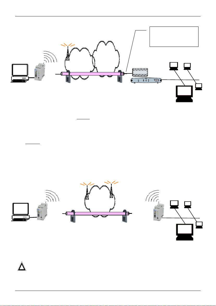
Scenario 1:
Dedicated line to GPRS
or Internet (with fixed,
known IP address)
GPRS
Internet
pplication
TAINY
GMOD-V2-IO
IPSec tunnel
Firewall
Router with
Firewall
Server in
company
network
The application is connected local ly
direct to the SINAUT MD740-1: e.g. statement
printer, notebook or PC. This application uses the SINAUT MD740-1 in order to have
secure access to a remote LAN as if it were connected direct to the LAN.
The remote
site is a computer in a corporate network. The network, protected by a VPN
router with firewall, is connected to the GPRS network or the Internet and has a known
or definable IP address.
Scenario 2:
GPRS
pplication
TAINY
GMOD-V2-IO
IPSec tunnel
TAINY GMOD-V2-IO
Server in
company
The remote site is another SINAUT MD740-1.
The direct connection of two GPRS end devices is not technically supported in
!
all GSM/GPRS networks.
LAN
LAN
8 von 105 SINAUT MD740-1
Page 9

Introduction
1.1 To be able to use the SINAUT MD740-1...
you require...
• a subscriber contract with a GSM network operator (e.g. TD1,
Vodafone, E-Plus, O2) that supports GPRS
• release of the GPRS for the user in question by the network
operator
1.2 IP address of the remote site
In order that a SINAUT MD740-1 can actively establish a VPN connection the remote
site must have a fixed IP address (an IP address consists of a maximum of 4 numbers,
separated by dots, which can each have up to three digits, e.g. 255.122.201.005). With
many Internet Service Providers (ISPs), however, the IP addresses are assigned
dynamically, i.e. the IP addresses of the computers or networks which have access to
the Internet change. There are 3 ways of obtaining a fixed IP address:
Fixed IP address via
dedicated line to
GPRS
Fixed IP address via
Internet service
provider
Fixed IP address via
DynDNS service
The communication partner is connected to the GPRS network
via a leased dedicated line. In this case it has normally been
assigned a fixed IP address by the network operator.
The communication partner can be accessed via the Internet and
has been assigned a fixed IP address by the Internet service
provider (the address can be applied for from some Internet
service providers).
To solve the problem of dynamic IP address assignment,
DynDNS services can be used. With this kind of service, the
SINAUT MD740-1, for example, or the remote computer,
regardless of the dynamic IP address it currently possesses, is
accessible via a fixed domain name. Each time the IP address
changes, the SINAUT MD740-1 or the remote computer reports
the new IP address to the DynDNS server, so that the current IP
address is always assigned to the domain name on the DNS
server - see glossary, page 95.
The use of a DynDNS service requires a contract with the
provider concerned, e.g. DynDNS.org or DNS4BIZ.com.
SINAUT MD740-1 9 von 105
Page 10
The LEDs of the SINAUT MD740-1
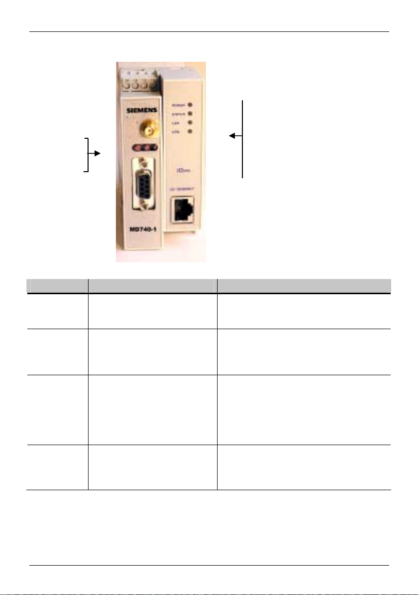
2 The LEDs of the SINAUT MD740-1
LEDs
S (Status)
Q (Quality)
C (Connect)
LEDs
Power
Status
LAN
VPN
S (Status), Q (Quality), C (Connect)
LED Status Meaning
S, Q, C
in sequence
S (Status)
Q (Quality)
C (Connect)
* When updating the communication firmware, at first the LEDs are slowly blinking in sequence.
Further in the process only the LED S is On.
** Shortly after booking into the GSM network, the quality LED blinks once, thus signalling the field
strength as not sufficient or unknown. Cause: At this stage the device can only register availability
Fast lighting in sequence
Slowly lighting in sequence
Synchronous fast blinking
Blinks slowly
Blinks fast
OFF
ON
Blinks slowly
1 x intermittent blinking
2 x intermittent blinking
3 x intermittent blinking
ON always
OFF
OFF
ON
Boot procedure
Update*
Error
Device waiting for PIN input
PIN error / SIM error
No GPRS attach
GPRS attach
Booking into the GPRS network
Field strength not sufficient or unknown**
Field strength sufficient
Field strength medium
Field strength high
Waiting for PIN input
No connection
Connection to server/remote station
GPRS: Authentication on and IP
allocation from network successful
10 von 105 SINAUT MD740-1
Page 11

The LEDs of the SINAUT MD740-1
of signal, but not the signal quality. The field strength is then requested in a next check, 15
seconds later.
DC5V, STAT, LINL, VPN
LED Colour Status Meaning
DC5V
Green ON Device switched on, operating voltage is on
OFF Device switched off, no operating voltage
STAT
Yellow Blinking IOVPN board operational
LINK
Yellow ON Ethernet connection to local PC / LAN
established
OFF No Ethernet connection to local PC / LAN
VPN
Yellow ON VPN tunnel established*
OFF VPN-Tunnel not established
* Shortly after switching on of the SINAUT MD740-1, the LED VPN is set to on for a short period of
time although the VPN tunnel has not yet been established. Cause: self-test of the components
during starting procedure of the device.
SINAUT MD740-1 11 von 105
Page 12
Putting the device into operation
3 Putting the device into operation
To put the device into operation, perform the following steps in the order given:
. 50 Ohm
Page
)
1.
Connect the device 12
2.
Configure the PIN 14
3.
Insert or change the SIM card 15
4.
Perform further configuration 19
!
First tell the device the PIN of the SIM card. Then insert the SIM card.
!
The device also supports SIM cards without a PIN. If your SIM card has no PIN you
can also insert the SIM card before performing configuration.
!
The device must be switched off when you insert or remove the SIM card.
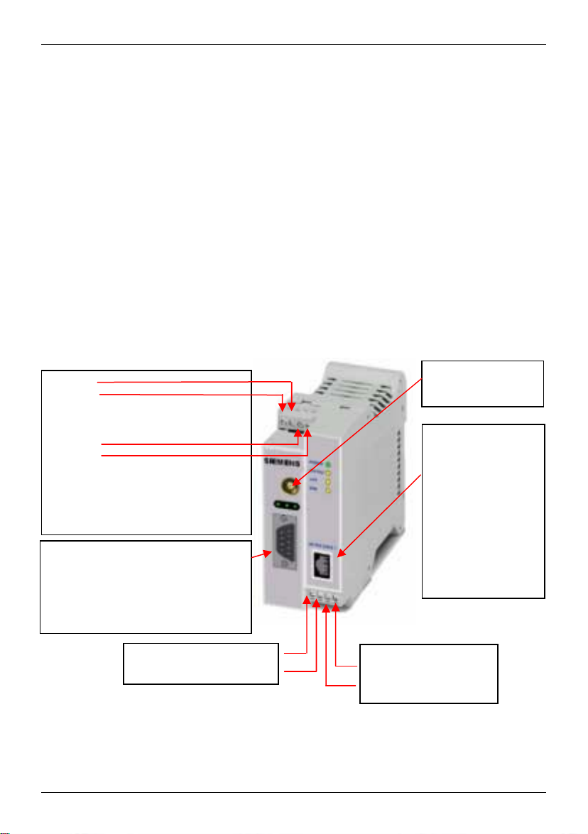
3.1 Connecting the device
Current supply: The screw terminals on top of the device for connecting of the current
supply: 24 V DC voltage (nominal), max. 600mA
+ 24 V
+ 24 V
0 V
0 V
Both terminal screws to the left (24 V)
are connected.
Both terminal screws to the right (0 V)
are connected.
Service interface.
Optional:
For the connection of a PC to display
device, status and connection
information.
To connect, use a V.24 cable.
Digital gate input I1+
I1-
Digital gate output
O1a
O1b
Antenna
(approx
Application interface.
Connect the
application device
here.
When connecting to
the network card of a
computer use a crossover Ethernet cable.
When connecting to
the network use a
UTP cable (CAT 5).
12 von 105 SINAUT MD740-1
Page 13

Putting the device into operation
Switching the device on/off
The SINAUT MD740-1 switches on as soon as the operating
voltage is supplied (see Connecting the device, page 12).
The devices switches off when disconnected from the supply
voltage.
When switching on
When the device is switched on the POWER LED comes on first. If
the device has a valid configuration and the SIM card is inserted
the device automatically books into the GPRS network. When the
CONNECT LED comes on a GPRS connection has been
established.
The device is designed in such a way that it can be left switched on
permanently.
SINAUT MD740-1 13 von 105
Page 14
Putting the device into operation
3.2 Configuring the PIN
In order for the SINAUT MD740-1 to be able to communicate via the GPRS network of
your network operator you must tell the device the PIN (Personal Identification Number)
of the SIM card. Then you can insert the SIM card into the device.
The device also supports SIM cards without a PIN. If your SIM card has no PIN it is not
necessary to configure the PIN. You can then insert the SIM card immediately.
To configure the PIN, proceed as follows:
1. Using your Web browser (e.g. MS Internet Explorer), establish a
configuration connection with the SINAUT MD740-1.
To do this, follow the description in section 4 Configuration,
page 19 to 23.
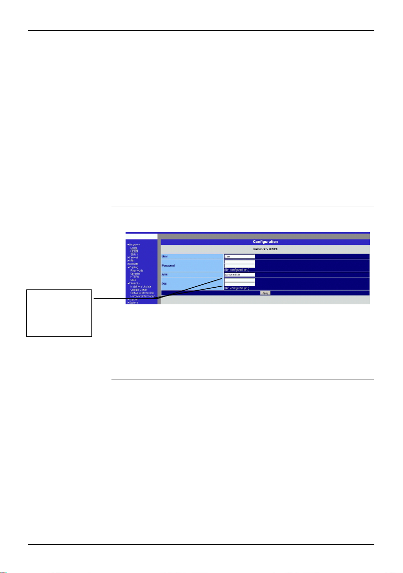
2. When the Administrator website of the SINAUT MD740-1
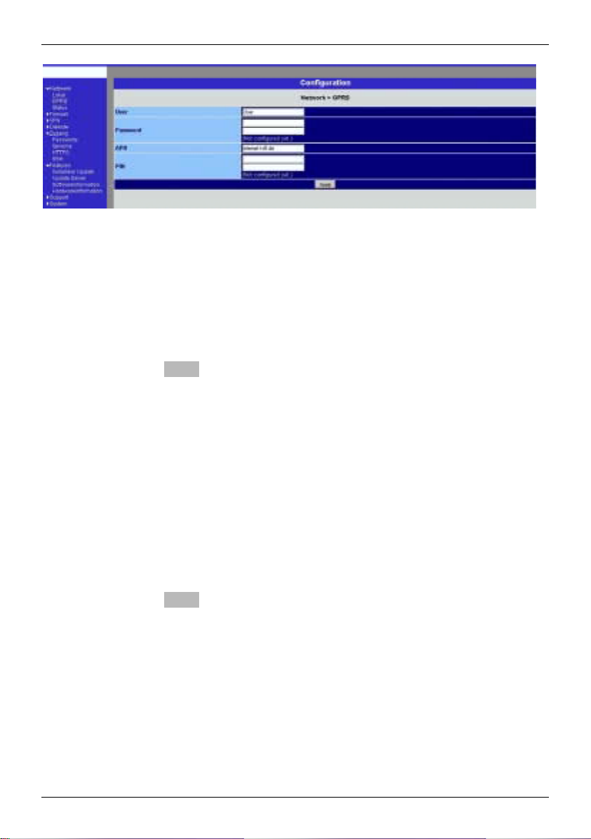
appears, select Network #### GPRS.
Enter PIN
(in both fields)
3. You can close the connection by closing the Web browser.
14 von 105 SINAUT MD740-1
In the PIN field, enter the PIN of the SIM card that you then
want to insert into the device.
!
Enter the same PIN in both fields.
Then click on OK or Apply.
Once the PIN is set, the message "Not configured yet" is no
longer displayed.
Page 15
Putting the device into operation
3.3 Inserting or changing the SIM card
!
SINAUT MD740-1 must be switched off when you insert or change the SIM card
!
A plug-in SIM card (3 Volt) is used.
1. Make sure that the device is disconnected from the supply voltage.
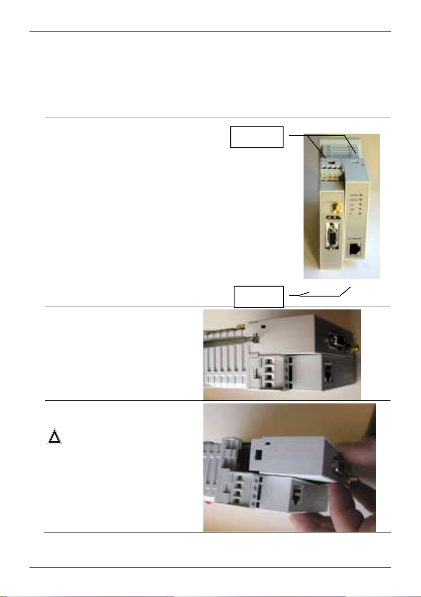
2. The SINAUT MD740-1 must be
opened to insert the SIM card.
The housing is fastened with clamps,
two each on top of the housing and on
the bottom side.
Clamps
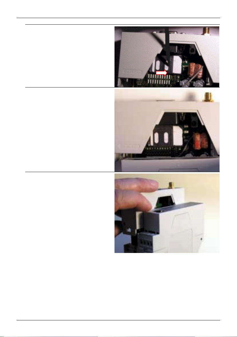
3. Release the two clamps on the
housing part with antenna socket.
For this purpose, press the clamps
cautiously with a suitable object (see
picture) so that catch opens.
4. Cautiously pull the unlocked housing
part so that the housing opens.
!
The boards in both front housing
parts are connected by an IO
cable. When opening the housing
make sure that the cable
connection is not loosened or
damaged. If necessary, unlock
both front housing parts and
cautiously pull them out together.
Clamps
SINAUT MD740-1 15 von 105
Page 16
Putting the device into operation
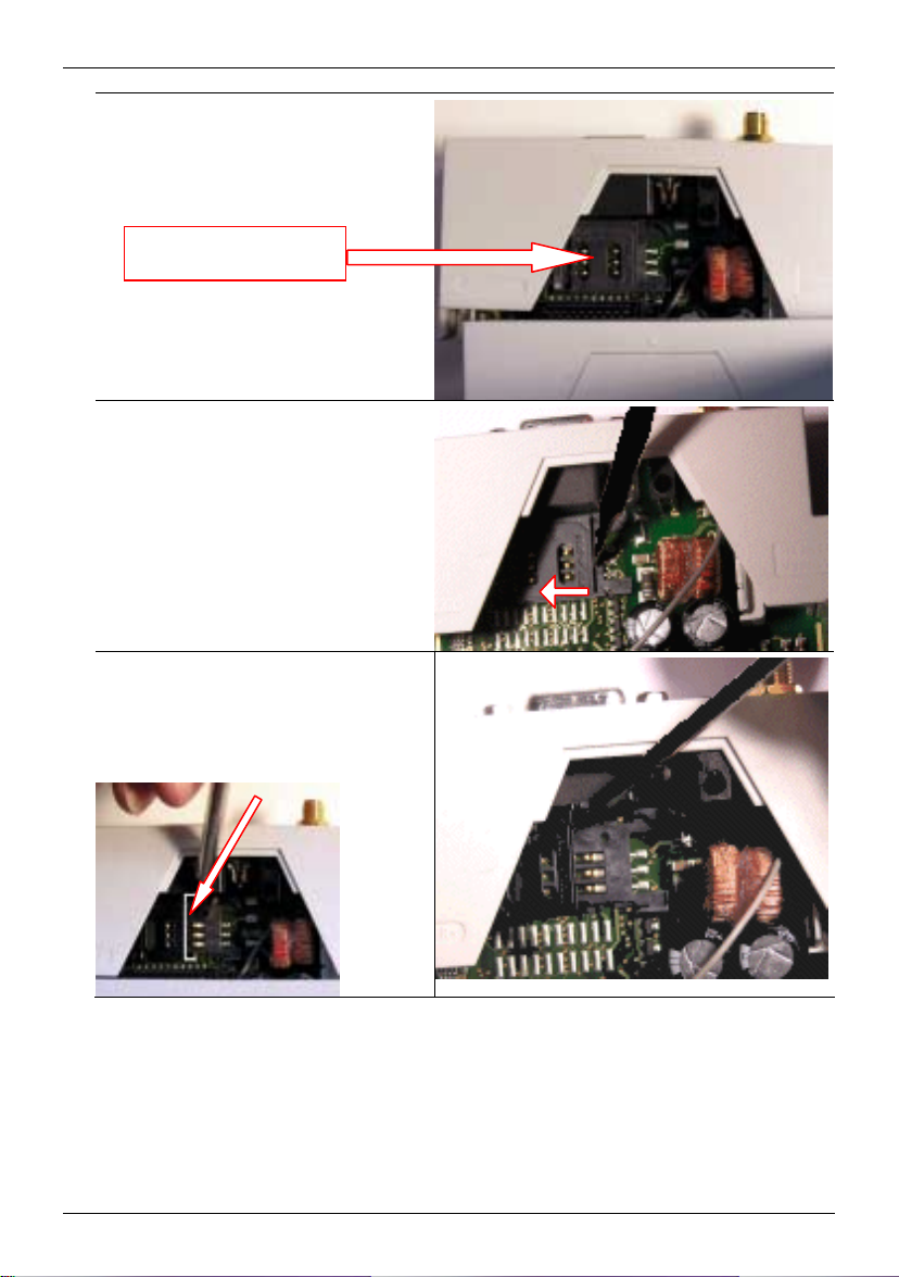
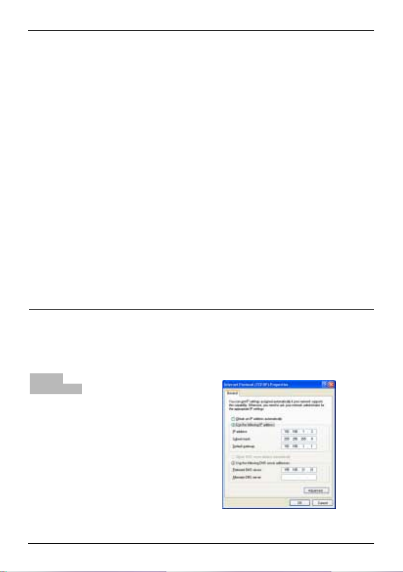
5. The SIM card holder is visible on the
motherboard.
SIM card holder
6. With a suitable object open the flap of
the SIM card holder by moving it
cautiously about 2mm to the left – in
the direction of the arrow (see red
arrow in the illustration) so that it can
be raised.
7. Raise the flap of the SIM card holder
so that you can insert the SIM card.
In the illustration below, the
compartment into which you can insert
the SIM card is emphasized in white.
16 von 105 SINAUT MD740-1
Page 17
Putting the device into operation
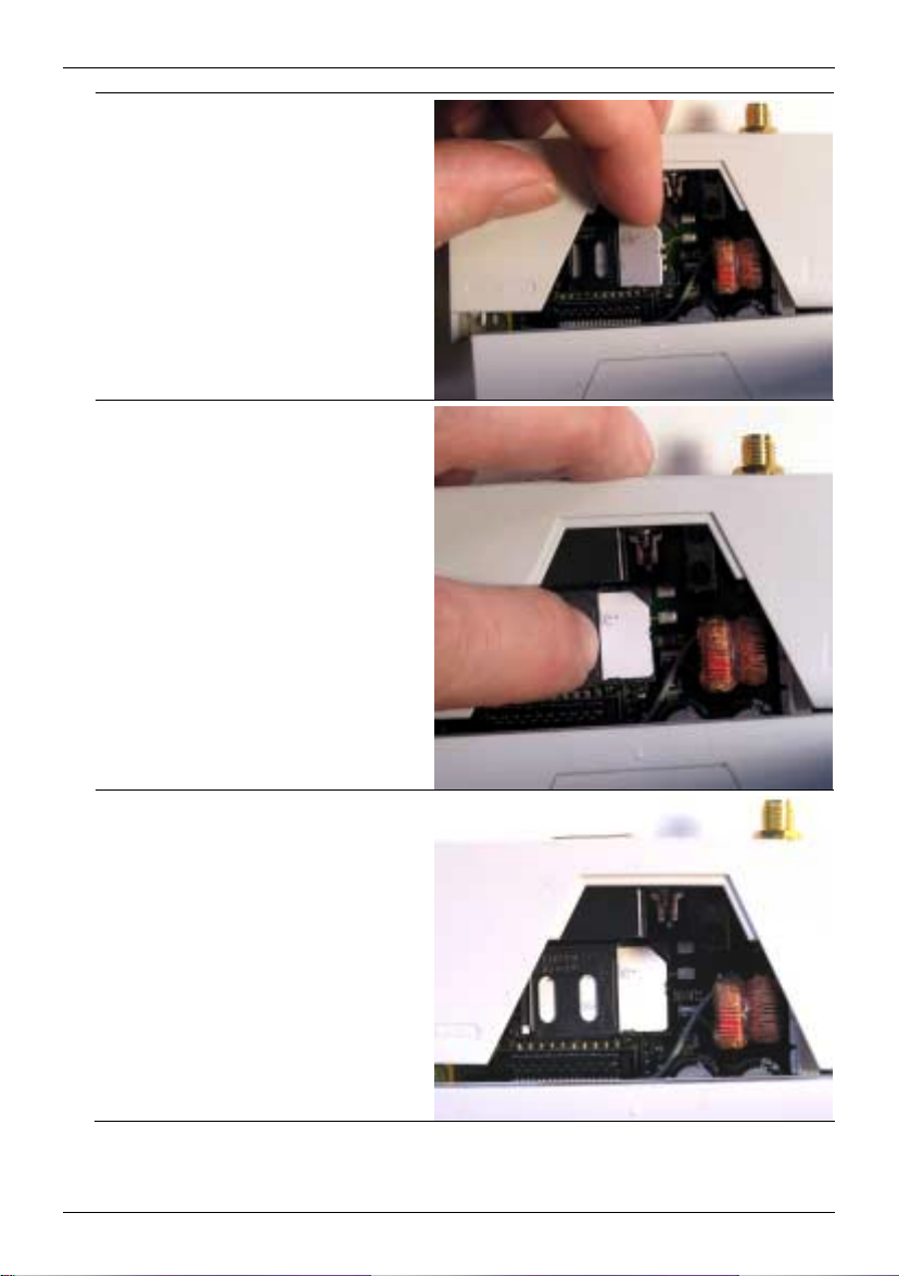
8. Slide the SIM card into the flap of the
SIM card holder, with the goldcoloured microchip pointing down. The
flap has a groove for this purpose. The
notched corner of the SIM card has to
point towards the front of the device
(see illustration).
9. Slide the SIM card down into the flap
as far as possible.
10. Lower the flap paying attention to the
notched corner of the SIM card (see
illustration).
SINAUT MD740-1 17 von 105
Page 18
Putting the device into operation
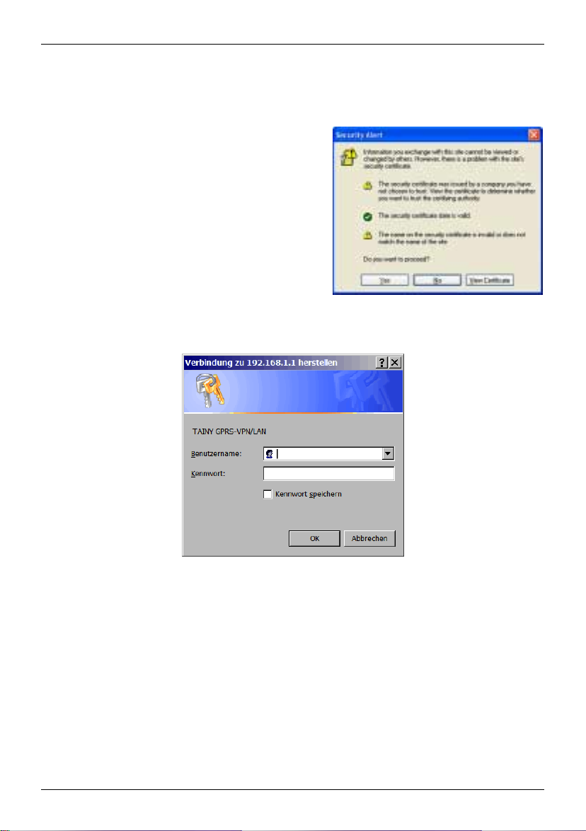
11. With your fingernail or a suitable object
move the flap about 2 mm to the right
(in the direction of the arrow) until you
can feel it click into place.
12. Now the SIM card holder is locked into
position.
13. Check the connection of the internal IO
connection cable.
Finally re-attach both housing parts:
Slide the motherboard into the rails on
top and bottom inside the rear section
of the housing. Close the housing by
slightly pressing the housing parts
together so that the clamps on the
upper and lower parts of the housing
engage.
The housing is locked when all clamps
have clicked shut.
18 von 105 SINAUT MD740-1
Page 19
Configuration
4 Configuration
Remote
configuration
Prerequisites for
local configuration
TCP/IP configuration of the network adapter under Windows XP:
TCP/IP
configuration of
the network
! Remote configuration is possible only if the SINAUT MD740-1 is
configured for remote access (see page 64). In this case,
proceed exactly as described as from section Establish
configuration connection, page 20.
• The computer with which you are performing the configuration
must either
-
be connected direct to the Ethernet socket of the
SINAUT MD740-1 via cross-over network cable
-
or it must have direct access via LAN to the
SINAUT MD740-1.
• The SINAUT MD740-1 must be switched on.
• The network adapter of the computer with which you are
performing configuration must hav e the follow ing T CP/IP
configuration:
IP address: 192.168.1.2
Subnet mask: 255.255.255.0
Default gateway: 192.168.1.1
Preferred DNS server: address of the Domain Name Server
Click on Start, Settings, Control Panel, Network
1.
Connections: right-click on the icon for LAN adapter and click
on Properties in the context menu.
adapter
…under
Windows XP
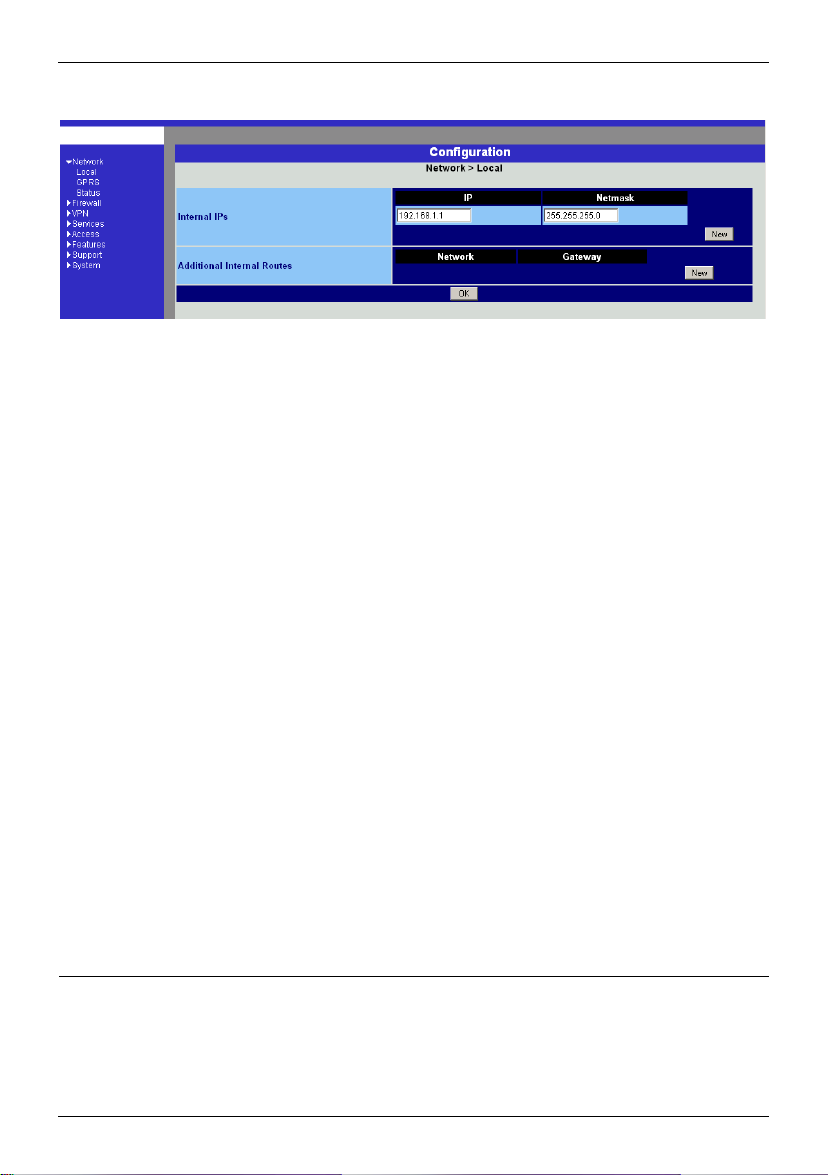
On the General tab in
the Properties of LAN
connection local
network dialogue box,
select the Internet
Protocol (TCP/IP) entry
and then click on the
Properties button to
make the following
dialogue box appear:
SINAUT MD740-1 19 von 105
Page 20

Configuration
2.
…under
Windows 2000
!
Preferred DNS
server
Establish
configuration
connection
2. Make sure that the browser does not automatically dial up a
IP address of the
SINAUT MD740-1:
https://192.168.1.1
Enter the following:
IP address: 192.168.1.2
Subnet mask: 255.255.255.0
Default gateway: 192.168.1.1
Preferred DNS server: address of the Domain Name Server
Under Windows 2000, proceed accordingly.
If you call up addresses via a domain name (e.g.
www.neuhaus.de), a Domain Name Server (DNS) has to look
up which IP address belongs to the name. You can determine
the following as the Domain Name Server:
• the DNS address of the network operator
OR
• the local IP address of the SINAUT MD740-1, provided that
it is configured to resolve hostnames in IP addresses, see
Services menu.
To determine the Domain Name Server in the TCP/IP
configuration of your network adapter, proceed as described
above.
Proceed as follows:
1. Start a Web browser.
(e.g. MS Internet Explorer from Version 5.0 or Netscape Communicator
from Version 4.0; the Web browser must support SSL (i.e. https))
connection when starting.
In MS Internet Explorer you make this setting as follows: menu
Tools, Internet Options..., Connections tab: under Dial-up and
Virtual Private Network settings, Never dial a connection must
be activated.
3. In the address line of the browser, enter the full address of the
SINAUT MD740-1. In accordance with the default setting, this
is:
https://192.168.1.1
Consequence: the security alert show n on the nex t page
appears.
20 von 105 SINAUT MD740-1
Page 21

Configuration
r
t
!
the Administrato
website does no
appear...
In case
If the browser still tells you after several attempts that the page
cannot be displayed, try the following:
• Check the hardware connection.
To do so on a Windows computer, enter the following
command via the DOS prompt (menu Start, Programs,
Tools, Command Prompt):
ping 192.168.1.1
If there is no
packets within the prescribed time, check the cable, the
connections and the network card.
• Make sure that the browser does not use a proxy server.
In MS Internet Explorer (Version 6.0) you make this setting as
follows: menu Tools, Internet Options..., Connections tab:
under LAN Settings click on the Settings button, in the
Settings for local area network (LAN) dialogue box make sure
that the Use a proxy server for your LAN entry is not
activated.
• If there are other LAN connections active on the computer,
deactivate them for the duration of configuration.
Under Windows menu Start, Settings, Control Panel,
Network Connections / Network and Dial-up
Connections right-click on the appropriate icon and select
Deactivate in the context menu.
• Enter the address of the SINAUT MD740-1 plus slash:
message about the reception of the 4 sent
https://192.168.1.1/
SINAUT MD740-1 21 von 105
Page 22
Configuration
When the
connection is
4. Following the successful estab lishment of the connection the
following security alert appears:
successfully
established...
Explanation:
As the device can only be
administered via
encrypted accesses it is
supplied with a self-signed
certificate.
Acknowledge the security alert with Yes.
5. You are prompted to enter the user name and the password.
The default setting is:
User name: admin
Password: tainy
Start page of the
Administrator
website
22 von 105 SINAUT MD740-1
6. Consequence: the Administrator website of the
SINAUT MD740-1 appears - see next page.
Page 23

Configuration
Perform
configuration
If a page is not up to date when next displayed because the
!
Depending on how you configure the SINAUT MD740-1, you may then have to
adapt the network interface of the connected computer or network accordingly.
!
When entering IP addresses, always enter the IP address sub-numbers without
the leading zeros, e.g.: 192.168.0.8.
Please note:
In the following screenshots of the configuration pages of the SINAUT MD740-1 are
displayed. The caption of these screenshots refers to another product from SIEMENS
A&D. This product basically supports the same features as SINAUT MD740-1 (VPN,
Firewall) but has a different housing.
To perform the configuration, proceed as follows:
1. Call up the
required setting
area via the menu.
2. Make the required
entries on the page
concerned.
3. Confirm with OK or
Apply, so that the
settings are
accepted by the
device.
browser is loading it from the cache, refresh the page display .
To do so, click on the Refresh icon in the browser's icon bar.
SINAUT MD740-1 23 von 105
Page 24
Configuration
4.1 Network menu
Network #### Local
Local IP address of
the SINAUT MD7401 according to
default setting:
192.168.1.1
Internal IPs
An internal IP is the IP address at which the SINAUT MD740-1 can
be accessed by devices of the locally connected network.
The default setting for the IP address is as follows:
IP address: 192.168.1.1
Local netmask: 255.255.255.0
You can determine further addresses at which the
SINAUT MD740-1 can be accessed by devices of the locally
connected network. This is helpful if, for example, the locally
connected network is divided into subnets. In this case, several
devices from different subnets access the
SINAUT MD740-1 at different addresses.
! If you want to determine a further internal IP, click on New.
You can determine any number of internal IPs.
! If you want to delete an internal IP, click on Delete.
(The first IP address in the list cannot be deleted.)
Additional Internal Routes
If further subnets are connected to the locally connected network,
you can define additional routes.
See also Network example diagram , page 81.
! If you want to determine a further route to a subnet, click on
New.
Enter the following:
- the IP address of the subnet (network), and
- the IP address of the gateway via which the subnet is
connected.
You can determine any number of internal routes.
! If you want to delete an internal route, click on Delete.
24 von 105 SINAUT MD740-1
Page 25
Configuration
Network #### GPRS
User (user name)
Password
When the SINAUT MD740-1 logs into the GPRS network it is
generally asked for the user name and the password before it is
given access to the network.
Some GSM/GPRS network operators dispense with access
control via user name and/or password. In this case, enter
visitor in the appropriate field.
INFO: Documentation from your network operator.
!
Enter the password identically in both fields.
Once the password has been set, the message "Not configured
yet" is no longer displayed.
APN (Access Point Name)
This denotes the gateway
-
to the Internet. In this case the remote site can be reached via
the Internet.
OR
-
to the private network. In this case the remote site is
connected to the GPRS network operator via a leased
dedicated line.
INFO:
• Internet APN:
You will find the APN in the documentation or at the website of
your GSM/GPRS network operator, or you can call the hotline
and ask for it there.
• Private APN:
You can obtain the access data from your network operator.
SINAUT MD740-1 25 von 105
Page 26
Configuration
When putting the
device into
operation:
1. Tell the device
the PIN of the
SIM card
2. Insert the SIM
card
PIN of the SIM card inserted in the device
In order for the SINAUT MD740-1 to be able to operate with the
SIM card of your network operator you must tell the device the PIN
(Personal Identification Number) of the SIM card, provided that the
SIM card has a PIN. Only after this should you insert the SIM card
into the switched off(!) device.
To do so, enter the PIN and click on OK or Apply.
If a PIN has been set, the message "Not configured yet" is no
longer displayed.
!
Enter the PIN identically in both fields.
!
The entered PIN must tally with the PIN of the SIM card with
which the device is to operate.
!
You cannot change the PIN of the SIM card with this device.
Confirm the entries on this configuration page by clicking on OK or
Apply.
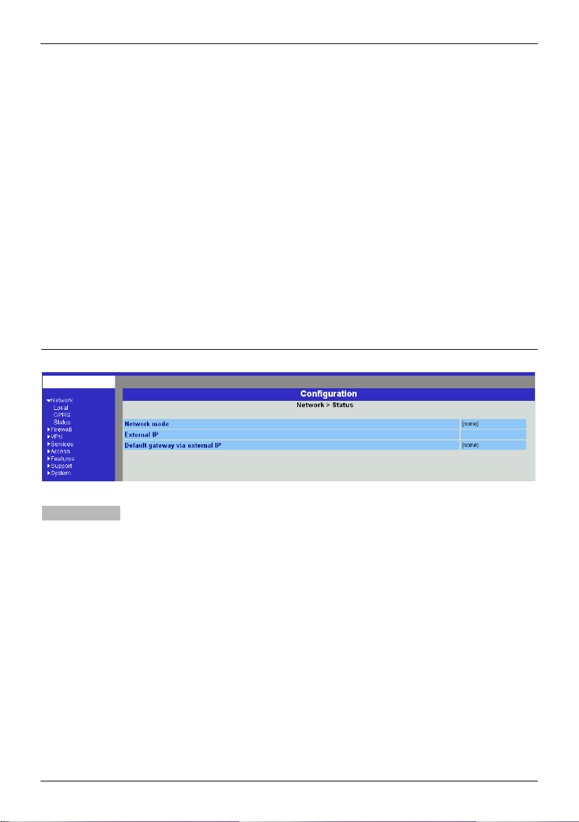
Network #### Status
Display only:
26 von 105 SINAUT MD740-1
Network mode
This indicates whether a GPRS connection has been
established (display: "modem connected") or whether the
GPRS modem is on standby and ready to establish a GPRS
connection (display: "(none)” or “modem (later)").
External IP /GPRS:
The IP address at which the device can be reached from the
outside. This IP address is assigned to the device by the
operator of the GPRS network for the current connection.
Default gateway via external IP:
IP address of the integrated GPRS module.
Page 27
Configuration
4.2 Firewall menu
The SINAUT MD740-1 comes with a Stateful Packet Inspection Firewall. The connection
data of an active connection are collected in a database (connection tracking). This
means that rules are only to be defined for one direction, while data from the other
direction of a connection, and only these, are allowed through automatically. A side
effect of this is that existing connections are not interrupted as a result of
reconfiguration, even if a corresponding new connection should no longer be
established.
Default firewall setting:
• All incoming connections are rejected (except VPN).
• The data packets of all outgoing connections are rejected (except VPN and except
connections to the integrated website which provides information about devices and
connection data).
!
VPN connections are not subject to the firewall rules determined under this menu
item. You can determine firewall rules for each individual VPN connection under the
menu VPN #### Connections.
!
If several firewall rules have been set, they are scanned in the order of the entries
from top to bottom until a suitable rule is found. This rule is then applied. Should
there also be rules further down in the list which would be also suitable, they are
ignored.
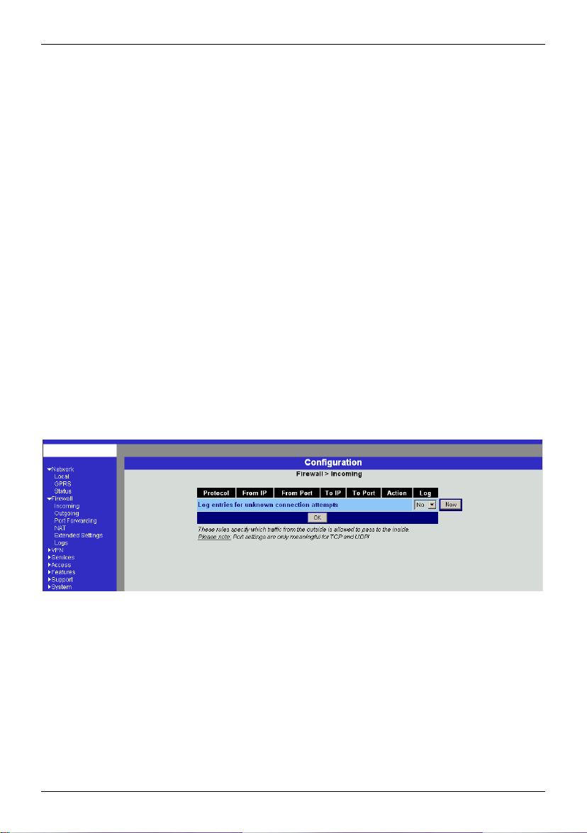
Firewall #### Incoming
SINAUT MD740-1 27 von 105
This lists the fixed firewall rules. These apply to incoming data
connections which have been initiated externally.
•
If no rule has been set, all incoming connections (except VPN)
are rejected (= default setting).
Deleting a rule
Click on Delete next to the entry concerned. Then click on OK
or Apply.
Page 28

Configuration
Setting a new rule
If you want to set a new rule, click on New.
Set the required rule (see below), then click on OK or Apply.
You receive a system message as confirmation.
You can make the following possible entries:
Protocol: All means: TCP, UDP, ICMP and others.
IP address: 0.0.0.0/0 means all addresses. To denote a range, use
CIDR syntax - see CIDR (Classless InterDomain Routing), page
79.
Port:
(is evaluated only with TCP and UDP protocols)
any means any port.
startport:endport (e.g. 110:120) denotes the port area.
Individual ports can be entered either with the port number or with
the corresponding service name: (e.g. 110 for pop3 or pop3 for
110).
Action:
Accept means that the data packets may pass.
Refuse means that the data packets are turned away so that the
sender is informed of the refusal.
Reject means that data packets are not allowed to pass. They
are "swallowed" so that the sender is not informed of their
whereabouts.
Log:
For each individual firewall rule you can determine whether, when
the rule is applied,
- the event is to be logged - set Log to Yes
- or not - set Log to No (default setting)
Log entries for unknown connection attempts:
This logs all connection attempts which are not recorded by the
prevalent rules.
28 von 105 SINAUT MD740-1
Page 29
Configuration
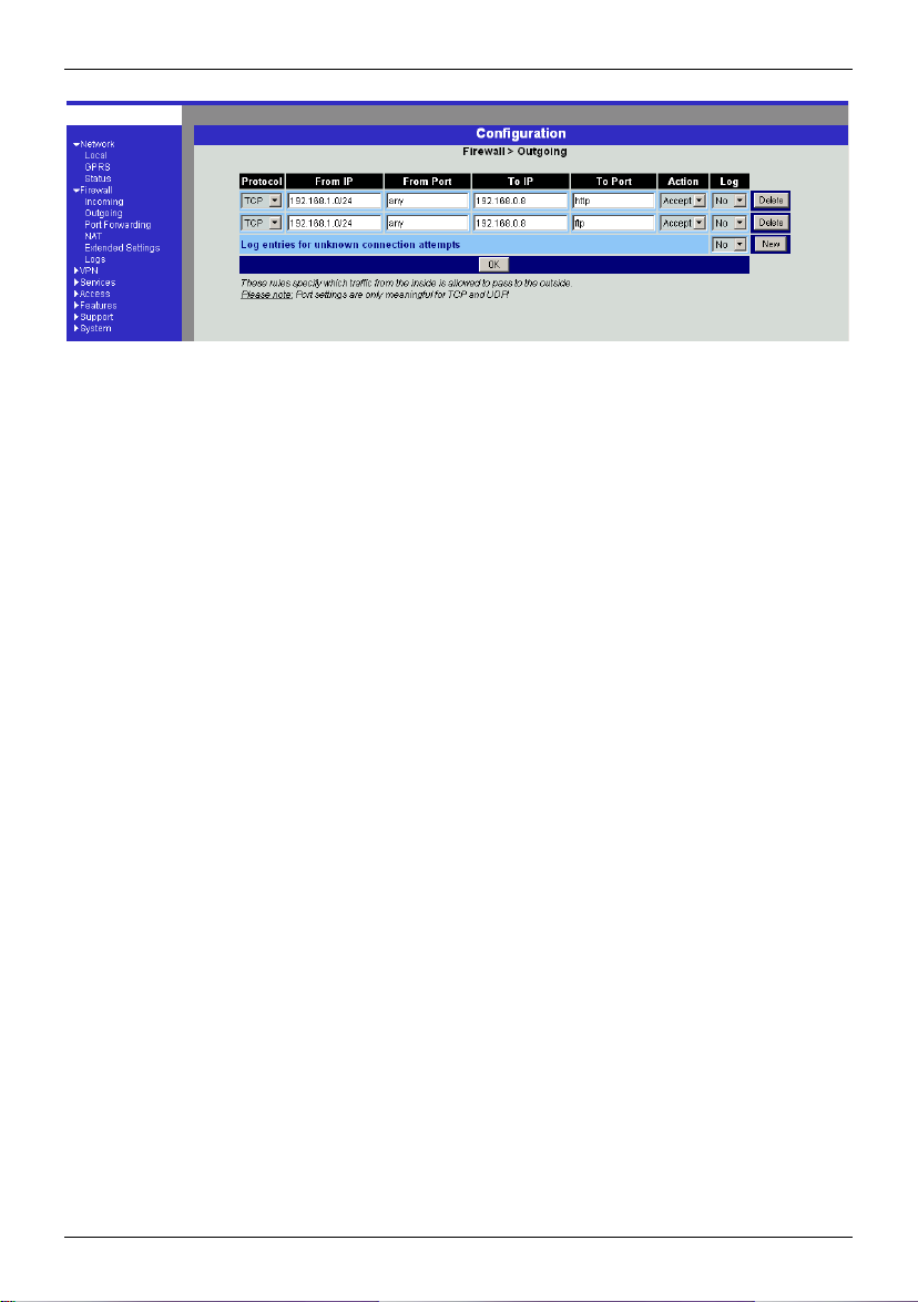
Firewall #### Outgoing
This lists the fixed firewall rules. These apply to outgoing data
packets which belong to GPRS connections initiated by the
SINAUT MD740-1 to communicate with a remote site.
!
If no rule is set, all outgoing connections are prohibited (except
VPN).
!
Default setting: outgoing connections prohibited (except VPN
and connections to the integrated website which provides
information about devices and connect ion data) .
Deleting a rule
Click on Delete next to the entry concerned. Then click on OK
or Apply.
Setting a new rule
If you want to set a new rule, click on New.
Set the required rule (see below), then click on OK or Apply.
You receive a system message as confirmation.
You can make the following possible entries:
Protocol: All means: TCP, UDP, ICMP and others.
IP address: 0.0.0.0/0 means all addresses. To denote a range, use
CIDR syntax - see CIDR (Classless InterDomain Routing), page
79.
Port:
(is only evaluated with TCP and UDP protocols)
any means any port.
startport:endport (e.g. 110:120) denotes the port area.
Individual ports can be entered either with the port number or with
the corresponding service name: (e.g. 110 for pop3 or pop3 for
110).
Action:
Accept means that the data packets may pass.
Refuse means that the data packets are turned away so that the
SINAUT MD740-1 29 von 105
Page 30
Configuration
sender is informed of the refusal.
Reject means that data packets are not allowed to pass. They
are swallowed so that the sender is not informed of their
whereabouts.
Log:
For each individual firewall rule you can determine whether, when
the rule is applied,
- the event is to be logged - set Log to Yes
- or not - set Log to No (default setting)
Log entries for unknown connection attempts:
This logs all connection attempts which are not recorded by the
prevalent rules.
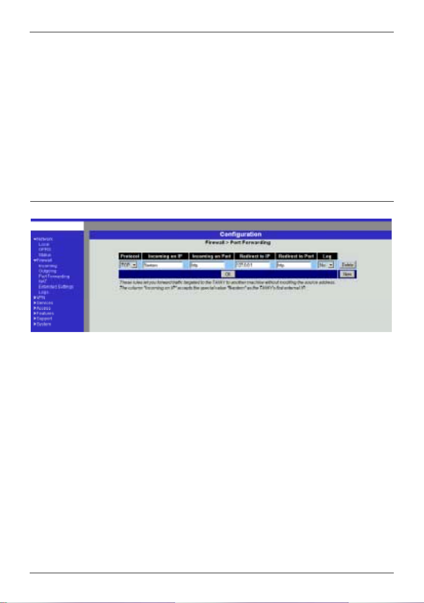
Firewall ####Port Forwarding
30 von 105 SINAUT MD740-1
This lists the fixed rules for port forwarding.
With port forwarding the following takes place: the header of
incoming data packets from the external network which are
intended for the external IP address (or one of the external IP
addresses) of the SINAUT MD740-1 and for a particular port of the
SINAUT MD740-1 are rewritten in such a way that they are
forwarded to the internal network to a particular computer and to a
particular port of this computer. That means that the IP address
and port number in the headers of incoming data packets are
changed.
This method is also called Destinat ion NAT .
!
The rules set here take priority over the settings under Firewall
#
# Incoming.
##
Deleting a rule
Click on Delete next to the entry concerned. Then click on OK
or Apply.
Setting a new rule
Page 31

Configuration
If you want to set a new rule, click on New.
Set the required rule (see below), then click on OK or Apply.
Protocol
Here you enter the protocol to which the rule is to apply.
Incoming on IP
Here you enter the external IP address (or one of the
external IP addresses) of the SINAUT MD740-1.
OR
Should a dynamic change of the external IP address of the
SINAUT MD740-1 take place, so that it cannot be given, use
the following variable: %extern.
The special value %extern refers to the first IP address in
the list when using several static IP addresses for the
external interface.
Incoming on Port
Original destination port that is given in incoming data
packets.
Redirect to IP
Internal IP address to which the data packets are to be
forwarded and to which the original destination addresses
are rewritten.
Redirect to Port
Port to which the data packets are to be forwarded and to
which the original destination addresses are rewritten.
You can make the following possible entries:
Port
You can only specify individual ports, either with the port
number or with the corresponding service name: (e.g. 110
for pop3 or pop3 for 110).
Log
For each individual port forwarding rule you can determine
whether, when the rule is applied,
- the event is to be logged - set Log to Yes
- or not - set Log to No (default setting).
SINAUT MD740-1 31 von 105
Page 32

Configuration
Firewall #### NAT
This lists the fixed rules for NAT (Network Address Translation) and
allows rules to be set or deleted.
For outgoing data packets the device can translate the given
sender IP addresses from its internal network to its own external
address, a technique known as NAT (Network Address
Translation).
This method is used when the internal addresses can not or should
not be routed, e.g. because a private address range such as
192.168.x.x or the internal network structure is to be hidden.
This method is also called IP Masquerading.
!
When using several static IP addresses for the external
interface, the first IP address in the list is always used for IP
Masquerading.
Default setting: NAT does not take place.
Deleting a rule
Click on Delete next to the entry concerned. Then click on OK
or Apply.
Setting a new rule
If you want to set a new rule, click on New.
Set the required rule (see below), then click on OK or Apply.
You can make the following possible entries:
From IP
0.0.0.0/0 means all addresses, i.e. all inter nal IP addresse s are
subjected to the NAT procedure. To denote a range, use
CIDR syntax - see CIDR (Classless InterDomain Routing),
page 79.
32 von 105 SINAUT MD740-1
Page 33

Configuration
Firewall #### Extended Settings
These settings determine the basic behaviour of the firewall.
Standard settings
All Modes
Maximum number ...
These 5 entries determine upper limits. They are selected in
such a way that they are never reached in normal practical
operation. In the event of attacks, however, they can easily
be reached, therefore the limitation represents built-in,
additional protection. Should special requirements exist in
your operating environment, you can increase the values.
Enable "FTP" NAT/Connection Tracking support
When an outgoing connection is establishe d in the FTP
protocol for the purpose of retrieving data, there are two
possible forms of data transmission: with "enabled FTP" the
called-up server in turn establishes an additional condition
to the caller in order to transmit the data via this connection.
With "disabled FTP" the client establishe s this add itio nal
SINAUT MD740-1 33 von 105
Page 34

Configuration
connection to the server for data transmission. In order for
the additional connections to be allowed through by the
firewall, Enable "FTP" NAT/Connection Tracking support
must be set to Yes (standard).
Enable "IRC" NAT/Connection Tracking support
Similar to FTP: when chatting on the Internet via IRC,
incoming connections must be allowed following the active
establishment of a connection if chatting is to work
smoothly. For these connections to be allowed through by
the firewall, Enable "IRC" NAT/Connection Tracking
support must be set to Yes (standard).
Enable "PPTP" NAT/Connection Tracking support
Must only be set to Yes if the following condition is present:
A VPN connection using PPTP is to be established to an
external computer from a local computer without the help of
the SINAUT MD740-1.
The default setting of this switch is No.
ICMP from extern to the TAINY
With this option you can influence behaviour when receiving
ICMP messages which are sent from the external network to
the SINAUT MD740-1. You have the following possibilities:
Reject: All ICMP messages sent to the
SINAUT MD740-1 are rejected.
Accept ping: Only ping messages (ICMP type 8) sent to the
SINAUT MD740-1 are accepted.
Accept all ICMPs: All types of ICMP messages sent to the
SINAUT MD740-1 are accepted.
34 von 105 SINAUT MD740-1
Page 35

Configuration
Firewall #### Logs
Display only:
If the logging of events (Log = Yes) has been determined during
the setting of firewall rules you can then view all the log of all
logged events here.
The format corresponds to that commonly used under Linux.
There are special evaluation programs which present the
information from the logged data in a more easily legible format.
SINAUT MD740-1 35 von 105
Page 36

Configuration
4.3 VPN menu
The general prerequisite for a VPN connection is that the IP addresses of the VPN
partners are known and accessible. See IP address of the remote site, page 9.
• In order for an IPSec connection to be established successfully the VPN remote site
must support IPsec with the following configuration:
- Authentication via Pre-Shared Key (PSK) or X.509 certificates
- ESP
- Diffie-Hellman groups 2 or 5
- DES, 3DES or AES encryption
- MD5 or SHA-1 Hash algorithms
- Tunnel or transport mode
- Quick mode
- Main mode
- SA Lifetime (1 second to 24 hours)
If the remote site is a computer running under Windows 2000, the Microsoft Wind ows
2000 High Encryption Pack or at least Service Pack 2 must be installed.
• If the remote site is behind a NAT router it must support NAT-T. Alternatively, the
NAT router must recognise the IPsec protocol (IPsec/VPN Passthrough). In both
cases, only IPsec tunnel connections are possible for technical reasons.
36 von 105 SINAUT MD740-1
Page 37

Configuration
VPN #### Connections
This lists the VPN connections already set up.
! You can enable (Enabled = Yes) or disable (Enabled = No)
each individual connection.
Deleting a VPN connection
Click on Delete next to the entry concerned.
Then click on OK or Apply.
Setting up a new VPN connection
Click on New.
Give the connection a name and click on Edit.
Perform the desired or necessary settings (see below).
Then click on OK or Apply.
Editing a VPN connection
Click on the Edit button next to the connection concerned.
Perform the desired or necessary settings (see following
illustration and explanations) .
Then click on OK or Apply.
SINAUT MD740-1 37 von 105
Page 38

Configuration
A descriptive name for the connection
You can name or rename the connection as you wish.
Enabled
Determine whether the connection is to be enabled (= Yes) or
not (= No).
38 von 105 SINAUT MD740-1
Page 39

Configuration
Address of the remote site's VPN gateway
• This denotes the address of the gateway to the private
network in which the remote communication partner is
located - see illustration below.
GPRS
IPsec tunnel
SINAUT MD740-1
Remote VPN
gateway address
• If the SINAUT MD740-1 is to initiate and establish the
connection actively with the remote site, then enter the
remote site's IP address here. Instead of an IP address you
can also enter a hostname (i.e. domain name in URL format
in the form www.xyz.de).
If the VPN gateway of the remote site does not have a fixed
and known address, a fixed and known address can
nevertheless be simulated by using the DynDNS service. See
IP address of the remote site, page 9.
• If the SINAUT MD740-1 is to be ready to accept the
connection actively initiated and established by a remote site
with any IP address to the local SINAUT MD740-1, then
enter: %any
Then a remote site which is assigned its own IP address (by
the Internet service provider) dynamically , i.e. has a changin g
IP address, can "call" the local SINAUT MD740-1.
If only one particular remote site with a fixed IP address
establishes the connection, you can enter this address to be
on the safe side.
!
In order for the SINAUT MD740-1 to accept a connection
actively initiated and established by a remote site, the
SINAUT MD740-1 requires a fixed IP address from the
provider or by using a DynDNS service.
!
In many GSM/GPRS networks it is not possible to set up
connections initiated from a remote site to the GPRS
device (SINAUT MD740-1).
Devices and addresses of remote site
Internet
Router with
firewall
Tunnel: the address
of the opposite
network (can also be
individual computer.)
LAN
SINAUT MD740-1 39 von 105
Page 40

Configuration
There are four options:
Connection type
• Tunnel (network $ # network)
• Transport (host $ # host)
• Transport (L2TP Microsoft Windows)
• Transport (L2TP SSH Sentinel)
Tunnel (network $$$$ #### network)
This connection type is suitable in every case and it is also
the safest. In this mode the IP datagrams to be transferred
are completely encrypted and sent with a new header to the
remote site's VPN gateway, the "end of the tunnel". There
the transferred datagrams are decrypted and the original
datagrams retrieved from them. These can then be sent to
the destination computer.
Transport (host $$$$ #### host)
With this connection type only the data in the IP packets are
encrypted. The IP header information is not encrypted.
Transport (L2TP Microsoft Windows)
If this connection is enabled on the remote computer, you
should also set the SINAUT MD740-1 to Transport (L2TP
Microsoft Windows). The SINAUT MD740-1 will then work
accordingly. The L2TP/PPP protocol creates a tunnel within
the IPsec Transport connection. The locally connected L2TP
computer is assigned its IP address dynamically by the
SINAUT MD740-1.
If you select the connection type Transport (L2TP Microsoft
Windows), set Perfect Forward Secrecy (PFS) to No (see
below). Also enable the L2TP server.
!
As soon as the IPsec/L2TP connection is started under
Windows, a dialogue box appears, asking for the user
name and login. You can enter anything here because
authentication has already taken place via the X.509
certificates, so that the SINAUT MD740-1 ignores these
entries.
40 von 105 SINAUT MD740-1
Page 41

Configuration
Transport (L2TP SSH Sentinel)
If this connection is enabled on the remote computer, you
should also set the SINAUT MD740-1 to Transport (L2TP
SSH Sentinel). The SINAUT MD740-1 will then work
accordingly. The L2TP/PPP protocol creates a tunnel within
the IPsec Transport connection. The locally connected L2TP
computer is assigned its IP address dynamically by the
SINAUT MD740-1. Also enable the L2TP server.
There are 2 possibilities:
There are 2 possibilities:
Connection startup
• Start the connection to the remote site
• Wait for the remote site
Start the connection to the remote site
In this case the local SINAUT MD740-1 initiates the
connection to the remote site. The fixed IP address of the
remote site or its domain name must be entered in the
Remote site's VPN gateway address field (see above).
Wait for the remote site
In this case the local SINAUT MD740-1 is ready to accept
the connection actively initiated and established by a remote
site to the local SINAUT MD740-1. %any can be entered in
the Remote site's VPN gateway address field (see above).
If only one particular remote site with a fixed IP address
establishes the connection, enter its IP address or host
name to be on the safe side.
!
In order for a connection to the
SINAUT MD740-1 to be established, the
SINAUT MD740-1 requires a fixed IP address from the
provider or by using a DynDNS service.
!
In many GSM/GPRS networks it is not possible to set
up connections initiated from a remote site to the GPRS
device (SINAUT MD740-1).
Authentication method
• X.509 Certificate
• Pre-Shared Key
SINAUT MD740-1 41 von 105
Page 42

Configuration
X.509 Certificate
This method is supported by most newer IPSec
implementations. The SINAUT MD740-1 encrypts the
authentication datagrams that it sends to the remote site the "end of the tunnel" - with the remote site's public key (file
name *.cer or *.pem). (You received this *.cer or *.pem file
from the operator of the remote site, e.g. on a disk or by email).
To make this public key available to the
SINAUT MD740-1, proceed as follows:
Prerequisite:
You have stored the *.cer or *.pem file on the locally
connected computer.
1. Click on Configure.
Consequence: The VPN > Connections > Connection
xyz > X.509 Certificate screen appears. ("xyz" is the
name of the connection concerned.)
2. Click on Browse... and select the file.
3. Click on Import.
After importing, the content of the new certificate is
displayed – see following illustration. You will find an
explanation of the displayed information in section VPN
#
Machine Certificate, page 48.
Pre-Shared Secret Key (PSK)
This method is supported mainly by older IPsec
implementations. The SINAUT MD740-1 encrypts the
datagrams which it sends to the remote site – the "end of
the tunnel" – with an agreed sequence of characters.
To make this agreed key available to the
SINAUT MD740-1, proceed as follows:
1. Click on Configure.
42 von 105 SINAUT MD740-1
Page 43

Configuration
Consequence: the screen illustrated below appears:
2. Enter the agreed sequence of characters in the field Pre-
Shared Secret Key (PSK). To obtain security
comparable to 3DES, the sequence of characters should
consists of approx. 30 randomly selected lower and
upper case characters and numerals.
3. Click on Back.
!
Pre-Shared Secret Key cannot be used with dynamic
(%any) IP addresses; only fixed IP addresses or hostnames
on both sides are supported.
Unlike ISAKMP SA (Key Exchange) (see above) the method
ISAKMP SA (Key Exchange)
Encryption algorithm
! Agree with the administrator of the remote site as to
which encryption method is to be used.
3DES-168 is the most commonly used method and is
therefore preset as the standard.
Basically, the following applies: the more bits an encryption
algorithm has – indicated by the number shown – the more
secure it is. The relatively new AES-256 method is therefore
considered to be the safest, but it is not yet so widespread.
The longer the key, the more time-consuming the encryption
process. This aspect is of no consequence to the
SINAUT MD740-1 because it works with hardware-based
encryption technology. Nevertheless, this aspect could be
significant for the remote site.
The selectable algorithm marked "Zero" con tains no
encryption at all.
Checksum algorithm/Hash
Leave the setting on All alg orit hm s. Then it makes no
difference whether the remote site works with MD5 or
SHA-1.
IPsec SA (data exchange)
SINAUT MD740-1 43 von 105
Page 44

Configuration
for data exchange is determined here. This may differ from
that of the Key Exchange, but not necessarily.
Encryption algorithm
See above.
Checksum algorithm/Hash
See above.
Perfect Forward Secrecy (PFS)
A method for the additional improvement of security during
data transfer. With IPsec, the keys for data exchange are
renewed at certain intervals. With PFS, new random
numbers are negotiated with the remote site instead of
deriving them from previously agreed random numbers.
Only if the remote site supports PFS, select Yes.
When selecting the connection type Transport (L2TP
Microsoft Windows) set Perfect Forward Secrecy (PFS) to
No.
Tunnel settings
Local network address
The appropriate netmask
With these two entries you give the address of the client
(network or computer) that is connected locally to the
SINAUT MD740-1 direct and which is protected by the das
SINAUT MD740-1. This address defines the loc al endp oint
of the connection.
Example:
If the computer that you are also using for the configuration
of the device is connected to the SINAUT MD740-1, then
these data could be:
Local network address: 192.168.1.1
The appropriate netmask: 255.255.255.0
See also Network example diagram , page 81.
44 von 105 SINAUT MD740-1
Page 45

Configuration
(
)
Local devices and
addresses
Tunnel: the address of the local network
can also be an individual computer
LAN
SINAUT MD740-1
Devices and addresses
of remote site
Tunnel: the address of the opposite network (can
also be an individual computer)
GPRS
Internet
GPRS
IPsec tunnel
To the remote
site
Internet
LAN
Router w.
firewall
Remote VPN
gateway address
SINAUT MD740-1
IPsec tunnel
SINAUT MD740-1 45 von 105
Page 46

Configuration
Remote network address
The appropriate netmask
With these two entries you give the address of the network in
which the remote communication partner is located. This
address can also be that of a computer which is connected
direct to the VPN gateway.
Firewall incoming, Firewall outgoing
While the settings performed under the menu item Firewall
apply only to non-VPN connections (see above under Firewall
#
Incoming, page 27), the settings here apply only to the VPN
connection defined here. In practical terms, that means: if you
have defined several VPN connections, you can restrict access
to each one from the outside or from the inside. Attempts to
bypass the restrictions can be recorded in the log.
!
According to the default setting the VPN firewall is set so
that everything is permitted for this VPN connection.
However, the extended firewall settings which are defined
and explained above still apply to each individual VPN
connection, independent of each other (see Firewall #
Extended Settings, page 33).
!
If several firewall rules have been set, they are scanned in
the order of the entries from top to bottom until a suitable
rule is found. This rule is then applied. Should there also
be rules further down in the list which would be also
suitable, they are ignored.
!
To set or delete a firewall rule, proceed exactly as
described above (see Firewall
Firewall # Outgoing, page 29.
As there, you can make the following possible entries:
Protocol:
All means: TCP, UDP, ICMP and other IP protocols.
IP address:
0.0.0.0/0 means all addresses. To denote a range, use
CIDR syntax - see CIDR (Classless InterDomain Routing),
page 79.
#
Incoming, page 27 and
46 von 105 SINAUT MD740-1
Page 47

Configuration
Port:
(is evaluated only with TCP and UPD protocols)
any means any port.
startport:endport (e.g. 110:120) denotes the port area.
Individual ports can be entered either with the port number
or with the corresponding service name (e.g. 110 for pop3
or pop3 for 110).
Action:
Accept means that the data packets may pass.
Refuse means that the data packets are turned away so
that the sender is informed of the refusal.
Reject means that data packets are not allowed to pass.
They are swallowed so that the sender is not informed of
their whereabouts.
Log
For each individual firewall rule you can determine whether,
when the rule is applied,
the event is to be logged - set Log to Yes
or not - set Log to No (default setting)
Log entries for unknown connection attempts:
This logs all connection attempts which are not recorded by
the prevalent rules.
!
If several firewall rules have been set, they are followed in
the order of the entries.
SINAUT MD740-1 47 von 105
Page 48

Configuration
A
VPN #### Machine Certificate
Certificate
This denotes the currently imported X.509 certificate with which
the SINAUT MD740-1 identifies itself to other VPN gateways.
fter a certificate has been imported the following information is
displayed:
subject
The owner to whom the certificate has been issued.
issuer
The certification office which has signed the certificate.
C: Country
ST: State
L: Location
O: Organisation
OU: Organisation Unit
CN: Common Name
MD5, SHA1 Fingerprint
Fingerprint of the certificate for comparison with
another one, e.g. on the telephone. Windows displays
the fingerprint in SHA1 format at this point.
notBefore, notAfter
Validity period of the certificate. Is ignored by the
SINAUT MD740-1 due to lack of an internal clock.
48 von 105 SINAUT MD740-1
Page 49

Configuration
The imported certificate file (filename extension *.p12 or *.pfx)
contains the information given above, as well the two keys: the
public key for encryption, the private key for decryption. The
appropriate public key can be assigned any number of
connection partners, enabling them to send encry pted data.
In agreement with the remote site, the certificate must be made
available to the operator of the remote site as a .cer or .pem
file, e.g. handed over personally or by e-mail. If you do not have
a secure mode of transfer, you should then compared the
fingerprint displayed by the SINAUT MD740-1 via a secure
channel.
Only one certificate file (PKCS#12 file) can be imported into the
device.
! To important a (new) certificate, proceed as follows:
New certificate
Prerequisite:
The certificate file (file name = *.p12 or *.pfx) is generated and
stored on the connected computer.
1. Click on Browse... to select the file.
2. Enter the password with which the private key of the
PKCS#12 file is protected in the field Password.
3. Click on Import.
4. Then click on OK or Apply.
After importing, you receive a system message:
SINAUT MD740-1 49 von 105
Page 50

Configuration
VPN #### L2TP
Start L2TP Server for IPsec/L2TP? Yes / No
If you want to enable an L2TP connection, set this switch to
Yes.
Within the IPsec transport connection the L2TP in turn contains a PPP
connection. Consequently, a kind of tunnel is created between 2
networks. The SINAUT MD740-1 informs the remote site via PPP as to
which addresses are being used: for itself and the remote site.
Local IP for L2TP connections
In the above screenshot the SINAUT MD740-1 is telling the
remote site that the device itself has the address 10.106.106.1.
Remote IPs for L2TP connections range
In the above screenshot the SINAUT MD740-1 is telling the
remote site that the remote site has the addresses from
10.106.106.2 (one computer) to 10.106.106.254 (several
computers).
50 von 105 SINAUT MD740-1
Page 51

Configuration
VPN #### IPsec Status
Display only:
Provides information on the status of the IPSec connect ion s.
The names of the VPN connections are on the left, their current
status on the right.
GATEWAY
denotes the communicating VPN gateways
TRAFFIC
denotes computers or networks communicating via the VPN
gateways.
ID
denotes the Distinguished Name (DN) of an X.509 certificate.
ISAKMP Status
ISAKMP Status (Internet security association and key
management protocol) is given as "established" if the two VPN
gateways involved have established a channel for key
exchange. In this case, they were able to contact each other
and all entries up to and including "ISAKMP SA" on the
configuration page of the connection were correct.
IPsec Status
IPsec Status is given as "established" when IPSec encryption is
enabled during communication. In this case, the entries under
"IPsec SA" and "Tunnel settings" were also correct.
If there are problems, it is recommended to look at the VPN logs of
the computer to which the connection was established, because
the initiating computer receives no detailed error messages for
security reasons.
The message
SINAUT MD740-1 51 von 105
Page 52

Configuration
ISAKMP SA established, IPsec State: WAITING
means:
Authentication was successful, but the other parameters were not
correct. Does the connection type (tunnel, transport) correspond? If
tunnel was selected, do the network areas on both sides
correspond?
The message
IPsec State: IPsec SA established
means:
The VPN has been successfully established and can be used.
However, if this is not the case, then there are problems with the
remote site's VPN gateway. In this case, tag the connection name
and then click on OK or Apply to restart the connection.
VPN #### L2TP Status
Display only:
Provides information the L2TP status if this has been chosen as the
connection type. See VPN
#
Connections, page 37.
If this connection type was not selected, see the display illustrated.
52 von 105 SINAUT MD740-1
Page 53

Configuration
VPN #### VPN Logs
Display only:
This lists all VPN events.
The format corresponds to that commonly used under Linux.
There are special evaluation programs which present the
information from the logged data in a more easily legible format.
SINAUT MD740-1 53 von 105
Page 54

Configuration
4.4 Services menu
Services #### DNS
If the SINAUT MD740-1 is to establish a connection to a remote
site (e.g. VPN gateway or NTP server), it must know the die IP
address of the remote site in question. If it is given the address in
the form of a domain address (i.e. www.abc.xyz.de), then the
device must consult a Domain Name Server (DNS) to see which IP
address is behind the domain address.
You can configure locally connected clients in such a way that they
can use the SINAUT MD740-1 to resolve hostnames into IP
addresses. See IP configur atio n with Wind ows cli ents, page 59.
Hostname mode
With Hostname Modus and Hostname you can give the
SINAUT MD740-1 a name. This name is then displayed, e.g.
when logging in by SSH. Giving names simplifies the
administration of several SINAUT MD740-1s.
User defined (from field below)
(Standard) The name entered in the field Hostname is set as
the name for the SINAUT MD740-1.
Provider defined (e.g. via DHCP)
If the external setting of the hostname is enabled, e.g. as with
DHCP, then the name supplied by the provider is set for the
SINAUT MD740-1.
Hostname
If the option User defined is selected under Hostname mode,
then you enter the name here which the
SINAUT MD740-1 is to receive.
Otherwise, i.e. when the option Provider defined (e.g. via
DHCP) is selected under Hostname mode, an entry in this field
is ignored.
Domain search path
54 von 105 SINAUT MD740-1
Page 55

Configuration
Makes it easier for the user to enter a domain name: if the user enters
the domain name in abbreviated form, the
SINAUT MD740-1 supplements his entry with the given domain suffix
which is fixed here under domain search path.
Servers to query
Possibilities: DNS Root Servers / Provider defined / User
defined
DNS Root Servers
Queries are directed to the DNS root servers on the Internet
whose IP addresses are stored in the
SINAUT MD740-1. These addresses rarely change. This
setting should only be selected if the alternative settings do
not work.
Provider defined (e.g. via PPPoE or DHCP)
The Domain Name Server of the Internet service provider is
used who provides access to the Internet. You can select
this setting with enabled DHCP (see Services
page 57).
User defined (from field below)
If this setting is selected, the SINAUT MD740-1 makes
contact with the Domain Name Servers which are listed
under User defined name servers.
User defined name servers
If you have set the option User defined under Servers to query,
in this list you configure the IP addresses of the Domain Name
Servers to be used.
To enable the locally connected clients can obtain the resolution
!
of hostnames in IP addresses from the
SINAUT MD740-1, you must determine the local IP address of
the SINAUT MD740-1 as the Preferred DNS server on the
clients.
See IP configuration with Windows clients, page 59.
#
DHCP,
SINAUT MD740-1 55 von 105
Page 56

Configuration
Services #### DynDNS Monitoring
Watch hostname of remote VPN Gateways? Yes / No
If the address of the remote VPN Gateway has been given to
the SINAUT MD740-1 as a hostname (see VPN
#
Connectio ns,
page 37), and if this Domain Name has been issued by a
DynDNS service, then the SINAUT MD740-1 can check
regularly whether any changes have been made to the DynDNS
concerned. If so, the VPN connection is established to the new
IP address.
Refresh Interval (sec)
Standard: 300 (sec)
Services #### DynDNS Registration
To establish VPN connections at least the IP address of one of the
partners must be known so that they can make contact with each
other. This condition is not fulfilled if both participants are assigned
their IP addresses dynamically by their Internet service providers.
In this case, however, a DynDNS service such as DynDNS.org or
DNS4BIZ.com can help. With a DynDNS service the currently valid
IP address is registered under a fixed name. See also IP address
of the remote site, page 9
Once you are registered with a DynDNS service supported by the
SINAUT MD740-1 you can make the corresponding entries in this
dialogue box.
Register this TAINY at a DynDNS Service? Yes / No
Select Yes if you are registered with a DynDNS provider and
the SINAUT MD740-1 is to use the service. Then the
SINAUT MD740-1 reports the current IP address assigned to its
own Internet connection by the Internet service provider to the
DynDNS service.
Refresh Interval (sec)
56 von 105 SINAUT MD740-1
Page 57

Configuration
Standard: 420 (sec).
Whenever the IP address of the device's own Internet
connection is or has been changed, the SINAUT MD 740-1
informs the DynDNS service of the new IP address. For
reliability reasons this message is also sent at the time intervals
fixed here.
DynDNS Provider
The selectable providers support the same protocol that is also
supported by the SINAUT MD740-1.
Enter the name of the provider with whom you are registered,
e.g. DynDNS.org
DynDNS Server
Name of the server of the DynDNS provider selected above,
e.g. dyndns.org
DynDNS Login, DynDNS Password
Here you enter the user name and the password assigned to
you by the DynDNS provider.
DynDNS hostname
The hostname selected for this SINAUT MD740-1 with the
DynDNS service – provided that you use a DynDNS service and
have given the appropriate details above.
Services #### DHCP
(DHCP = Dynamic Host Configuration Protocol) This function
automatically assigns the required network configuration (IP
address and subnet mask) to the client connected locally to the
SINAUT MD740-1.
SINAUT MD740-1 57 von 105
Page 58

Configuration
Start DHCP Server
Set this switch to Yes if you want to enable this function.
Enable dynamic IP address pool
Set this switch to Yes if you want to use the IP address pool
selected by DHCP range start and DHCP range end.
Set this switch to No if only static assignments based on the
MAC address are to be performed (see below).
Options:
If the DHCP server and the dynamic IP address pool are
enabled you can indicate the network parameters to be used by
the client
DHCP range start:
DHCP range end:
Start and end of the address range from
which the DHCP server of the
SINAUT MD740-1 is to assign IP
addresses to the locally connected
clients.
Local netmask: Default setting: 255.255.255.0
Default gateway: Determines which IP address is to be
used as the default gateway by the
client. This is usually the local IP
address of the
SINAUT MD740-1.
DNS server: Determines from where clients receive
resolution of hostnames in IP addresses.
If the DNS services of the SINAUT
MD740-1 is enabled it can be the local
IP address of the SINAUT MD740-1.
Client MAC address / client IP address
You can establish the MAC address of your client as follows:
Windows 95/98/ME: Start "winipcfg" in a DOS box
Windows NT/2000/XP: Start "ipconfig /all" in a prompt. The
MAC address is displayed as a "physical address".
Linux: Call up "/sbin/ifconfig" or "ip link show" in a shell .
Delete address
Click on Delete next to the entry concerned, then OK or Apply.
Add address
If you want to add a new address, click on New.
Enter the address data (see below) and click on OK or Apply.
Enter:
Client MAC address
The MAC address (without spaces or hyphens) of the client.
58 von 105 SINAUT MD740-1
Page 59

Configuration
Client IP address
The static IP that is to be assigned to the client's MAC
address.
!
The static assignments take priority over the dynamic IP
address pool.
!
Static assignments must not overlap with the dynamic IP
address pool.
!
An IP must not be used in several static assign men ts,
otherwise this IP will be assigned to several MAC
addresses.
!
Only one DHCP server per subnet must be used.
!
When you start the DHCP server of the
SINAUT MD740-1 you must configure the locally connected
clients in such a way that they receive their IP addresses
automatically (see below).
IP configuration with Windows clients
!
Under Windows XP, click on Start, Control Panel, Network
Connections: right-click on the LAN adapter icon and click on
Properties in the context menu. On the General tab in the
Properties of LAN connection local network dialogue box, tag
the Internet Protocol (TCP/IP) entry under "This connection
uses the following items" and then click on the Properties
button.
In the dialogue box Properties of Internet Protocol (TCP/IP),
make the required entries and settings.
Services #### NTP
(NTP = Network Time Protocol)
SINAUT MD740-1 59 von 105
Current system time (UTC)
Page 60

Configuration
Displays the current system time in Universal Time Coordinates
(UTC). If NTP time synchronization is not yet enabled (see
below) and Time stamps in file system are disabled, the clock
begins with 1 January 2000.
If the possibly deviating current local time is to be displayed you
Displays the current NTP state
As soon as the NTP is enabled the SINAUT MD740-1 sources
If you do not want the current Greenwich Mean Time to be
Current system time (local)
must make the corresponding entry under Time zone in
POSIX.1 Notation... (see below).
NTP State
Enable NTP time synchronization: Yes / No
the time from the Internet and displays it as the current system
time. Synchronization may take a few seconds.
Only if this switch is set to Yes and at least 1 time server is
given under NTP servers to synchroniz e to (see below) is the
current system time provided.
NTP servers to synchronize to
NTP Server
Here you can enter one or more NTP servers from which the
SINAUT MD740-1 is to source the current time. If you enter
several time servers, the SINAUT MD740-1 automatically
connects to all of them to ascertain the current time.
The SINAUT MD740-1 also provides the connec ted co mput e r s
with the NTP time.
!
Enter the IP addresses (instead of the hostnames) of the
required time servers.
Min. Poll / Max. Poll
Time synchronization takes place cy cli ca lly . Here you ente r the
interval at which the poll is to take place (poll interval).
The NTP client selects the poll interval dynamically between the
two values. Make sure that the minimum value entered is
smaller than the maximum value.
Time zone in POSIX.1 notation...
displayed under Current system time, but the current local time
(= deviating from Greenwich Mean Time), then you must enter
here by how many hours your local time is ahead or behind.
Examples:
In Hamburg the time is 1 hour ahead of Greenwich Mean
Time. So you enter: CET-1
If you want CET (= valid for Germany) to be displayed with
60 von 105 SINAUT MD740-1
Page 61

Configuration
automatic switching to summer or winter time, enter:
CET-1CEST,M3.5.0,M10.5.0/3
Time stamp in file system (2h granularity): Yes / No
If this switch is set to Yes, the SINAUT MD740-1 writes the
current system into its memory every 2 hours.
Consequence: If the SINAUT MD740-1 is switched off and then
back on, after being switched on a time in this 2-hour time
window will be displayed and not a time on 1 January 2000.
Services #### Remote Logging
All log entries take place by default in the flash memory of the
SINAUT MD740-1. If the maximum memory space for these logs is
exhausted, the oldest log entries are automatically overwritten by
new ones.
It is possible to transfer the log entries to an external computer.
This is advisable if, for example, logging is to administered
centrally.
If all log entries are to be transferred to the external log server
Enter the IP address of the log server to which the log entries
Enter the port of the log server to which the log entries are to be
Activate remote UDP logging: Yes / No
(specified below), set this switch to Yes.
Log Server IP address
are to be transferred via UDP.
!
The log server must have a fixed and known IP address.
!
You must enter the IP address, not a hostname. Name
resolution is not supported here because otherwise the
breakdown of a DNS server could not be reported.
Log Server port
transferred via UDP. Default: 514
SINAUT MD740-1 61 von 105
Page 62

Configuration
4.5 Access menu
Access #### Passwords
The SINAUT MD740-1 offers 3 levels of user rights. To log in at a
particular level the user must enter the password which is allocated
to the privilege level in question.
Privilege level
Root Provides extended rights for the parameters of the
SINAUT MD740-1.
!
With SSH access at this privilege level it is
possible to misconfigure the device in such
a way that it has to be sent in for servicing.
In this case, please contact your dealer or
distributor.
Default user name: root
Default root password: root
The user name root cannot be changed.
Administrator Provides the rights for all configuration options
which are also available via the web-based
administrator interface.
Default user: admin
Default password: tainy
The user name admin cannot be changed.
User Once a user password has been determined and
enabled, the user must then enter this passw ord
after each restart of the SINAUT MD740-1 when
accessing any HTTP URL in order to facilitate VPN
connections.
62 von 105 SINAUT MD740-1
Page 63

Configuration
If you want to use this option, determine a user
password in the corresponding entry field.
Root Password
Default setting: root
If you want to change the root password, enter the old password
in the field Old Password, then enter the new password in the
two fields below.
(unalterable user name: admin)
Administrator Password (Account: admin)
Default setting: tainy
(unalterable user name: admin)
Enable User Password: Yes / No
User password protection is switched off as default.
If a user password has been determined below, user password
protection can be enabled or disabled with this switch.
User Password
No user password is preset as default. To determine one, enter
the required password identically in each of the two entry fields.
Access #### Language
Please select your preferred language
If (Automatic) is selected in the language selection list, the
device automatically adopts the language setting from the
computer's browser.
SINAUT MD740-1 63 von 105
Page 64

Configuration
Access #### HTTPS
When HTTPS remote access is switched on, the
SINAUT MD740-1 can be configured via its web-based
administrator interface from a remote computer. This means that
the browser on the remote computer is used to configure the local
SINAUT MD740-1.
This option is switched off as default.
!
N.B.:
When you enable remote access, make sure that a secure root
and administrator password have been determined.
To enable HTTPS remote access, make the following settings:
Enable HTTPS remote access: Yes / No
If you want to enable HTTPS remote access, set this switch to
Yes.
!
In this case, make sure that the firewall rules on this page
are set so that the SINAUT MD740-1 can be accessed from
the outside.
!
If you set this parameter to No by remote access, no further
entries by HTTPS remote access are possible. This option
must then be accepted again, either locally or by SSH
remote access, provided that this has been configured.
Port for incoming HTTPS connec tions (remote
administration only)
Default: 443
You can determine a different port.
!
If you have determined a different port, the remote site
which makes the remote access must then give the port
number after the IP address in the address information.
Example:
If this SINAUT MD740-1 can be reached via the Internet
using the address 192.144.112.5, and if the port number
442 has been determined for remote access, then the
64 von 105 SINAUT MD740-1
Page 65

Configuration
following must be entered at the remote site in the web
browser:
192.144.112.5:442
Firewall rules to accept HTTPS access
This lists the fixed firewall rules. They apply to the incoming
data packet of a HTTPS remote access.
Delete rule
! Click on Delete next to the entry concerned.
Set new rule
! If you want to set a new rule, click on New.
Set the required new rule (see below) and click on OK or
Apply.
From IP
Here you enter the address(es) of the computer(s) which is/are
allowed remote access.
You can make the following possible entries:
IP address: 0.0.0.0/0 means all addresses. To denote a range,
use CIDR syntax - see CIDR (Classless InterDomain Routing),
page 79.
Interface
extern (fixed)
Action
Possibilities: Accept / Refuse / Reject
Accept means that the data packets may pass.
Refuse means that the data packets are turned away so that
the sender is informed of the refusal.
Reject means that data packets are not allowed to pass. They
are swallowed so that the sender is not informed of their
whereabouts.
Log
For each individual firewall rule you can determine whether,
when the rule is applied,
• the event is to be logged - set Log to Yes
• or not - set Log to No (default setting).
SINAUT MD740-1 65 von 105
Page 66

Configuration
Access #### SSH
When SSH remote access is switched on, the SINAUT MD740-1
can be configured from a remote computer. To do so, a connection
must first be established from the remote site to the
SINAUT MD740-1 using an SSH-capable program. To perform
settings in the SINAUT MD740-1 enter the command "gaiconfig"
via the SSH console.
This option is switched off as default.
!
N.B.:
When you enable remote access, make sure that a secure root
and administrator password have been determined.
!
N.B.:
With SSH access via the root password it is possible to
misconfigure the device in such a way that it has to be sent in
for servicing. In this case, please contact your dealer or
distributor.
To enable SSH remote access, make the following settings:
If you want to enable SSH remote access, set this switch to
Default: 22
Enable SSH remote access: Yes / No
Yes.
!
In this case, make sure that the firewall rules on this page
are set so that the SINAUT MD740-1 can be accessed from
the outside.
Port for incoming SSH connections (remote administration
only)
You can determine a different port.
!
If you have determined a different port, the remote site
which makes the remote access must then give the port
number that is set here before the IP address in the address
information.
Example:
66 von 105 SINAUT MD740-1
Page 67

Configuration
If this SINAUT MD740-1 can be reached via the Internet
using the address 192.144.112.5, and if a different port
number has been set for remote access, then this number
must be entered at the remote site in the SSH client (e.g.
web browser), e.g.
ssh -p 22222 192.144.112.5
Firewall rules to accept SSH access
This lists the fixed firewall rules. These apply to the incoming
data packets of an SSH remote access.
Delete rule
! Click on Delete next to the entry concerned.
Set new rule
! If you want to set a new rule, click on New.
Set the required new rule (see below) and click on OK or
Apply.
From IP
Here you enter the address(es) of the computer(s) which is/are
allowed remote access.
You can make the following possible entries:
IP address: 0.0.0.0/0 means all addresses. To denote a range,
use CIDR syntax - see CIDR (Classless InterDomain Routing),
page 79.
Interface
extern (fixed)
Action
Possibilities: Accept / Refuse / Reject
Accept means that the data packets may pass.
Refuse means that the data packets are turned away so that
the sender is informed of the refusal.
Reject means that data packets are not allowed to pass. They
are swallowed so that the sender is not informed of their
whereabouts.
Log
For each individual firewall rule you can determine whether,
when the rule is applied,
• the event is to be logged - set Log to Yes
• or not - set Log to No (default setting).
SINAUT MD740-1 67 von 105
Page 68

Configuration
4.6 Features menu
Features #### Install Update
Prerequisite: you have either
• stored a current software package locally on your configuration
computer
OR
• been provided with a current software package via a remote
server.
Ask your dealer or distributor whether and how you can obtain a
software update.
!
Under no circumstances should you disconnect the power
supply of the SINAUT MD740-1 during the update. The device
could be damaged and can only be reactivated by the
manufacturer.
If you have stored a current software update on your configuration
computer, proceed as follows:
1. Click on Browse... then select the file.
2. Click on Install Packages to load them into the device.
Depending on the size of the update, this procedure can take
several minutes.
If a reboot should be necessary following the system update, a
corresponding message will appear.
• If you are provided with a current software update on a remote
server, the server's address must be set - see Features
Update Server, page 69.
Proceed as follows:
1. Write the filename in the entry field.
#
68 von 105 SINAUT MD740-1
Page 69

Configuration
2. Click on Install Package Set to load it into the device.
Depending on the size of the update, this procedure can take
several minutes.
If a reboot should be necessary following the system update, a
corresponding message will appear.
Features #### Update Server
#
If you are provided with a software update (Features
Install
Update, page 68) for the SINAUT MD740-1 on a remote server,
enter the server's address here. This must always come before the
protocol used.
Examples: http://123.456.789.1 OR http: //www.xyz.com/update
SINAUT MD740-1 69 von 105
Page 70

Configuration
Features #### Software Information
Display only:
This lists the software modules contained in the device. These are
described as packets.
Serves update purposes: compare the displayed version numbers
with the current version numbers of the appropriate packets. To do
so, please contact your distributor.
Should new versions be available you can update the software in
the device. See Features
#
Install Update, page 68.
70 von 105 SINAUT MD740-1
Page 71

Configuration
Features #### Hardware Information
Display only:
For experienced system administrators / support.
SINAUT MD740-1 71 von 105
Page 72

Configuration
4.7 Support menu
Support #### Snapshot
This function serves support purposes.
It creates a compressed file (in tar format) containing all the current
configuration settings and log entries which cou ld be relev ant for a
fault diagnosis. (This file contains no private information such as
the private machine certificate or the passwords. However, any
used Pre-Shared Keys from VPN connections are contained in the
snapshots.)
To create a snapshot, proceed as follows:
1. Click on Download.
2. Store the file under the name snapshot.tar.gz
Make the file available to support if requested to do so.
72 von 105 SINAUT MD740-1
Page 73

Configuration
Support #### Status
Display only:
Displays a summary of different status information for support
purposes:
Network mode
Operating mode of the SINAUT MD740-1: modem
External IP
The IP address of the SINAUT MD740-1 at its connection for
the external network (WAN or Internet).
Default gateway via external IP
The external IP address of the SINAUT MD740-1.
VPN (Total / Used / Up)
Possibilities: Total / Used / Up
Total : total number of VPN connections set up
Used : VPN connections used
Up : VPN connections currently active
VPN User login
Possibilities: N/A / not logged in / logged in
N / A : not available
not logged in : VPN closed
logged in : VPN open
DynDNS registration
Possibilities: none / DynDNS server address / failure / trying
none : no DynDNS server
DynDNS server address : address of the DynDNS server used
by the SINAUT MD740-1 to resolve
hostnames
failure : the SINAUT MD740-1 is trying
unsuccessfully to connect to the
DynDNS server.
SINAUT MD740-1 73 von 105
Page 74

Configuration
trying : the SINAUT MD740-1 is trying to
connect to the DynDNS server.
HTTPS remote access
Possibilities: no / yes
SSH remote access
Possibilities: no / yes
NTP state
Possibilities: synchronized / not synchronized
synchronized : the SINAUT MD740-1 is receiving the
current time (Greenwich Mean Time) from a
time server via the Network Time Protocol.
not synchronized : the SINAUT MD740-1 is not connected to a
time server and therefore cannot provide
the current time.
Software version
Version of the software installed in the SINAUT MD740-1
System Uptime
Uptime since the last start-up of the SINAUT MD740-1
Language
Language currently set
74 von 105 SINAUT MD740-1
Page 75

Configuration
4.8 System menu
System #### Configuration Profiles
You have the possibility to save the settings of the
SINAUT MD740-1 as a configuration profile under any name in the
SINAUT MD740-1. You can create several such configuration
profiles. You can then activate whichever configuration profile you
require when using the
SINAUT MD740-1 in different operating environments.
Furthermore, you can save configuration profiles as files on the
hard disk of the configuration computer. Vice versa, you can upload
a configuration file created in this way to the
SINAUT MD740-1 and put it into effect.
In addition, you have the possibility to put the default setting (back)
into effect at any time.
!
When a configuration profile is saved, password and user
names are not saved with it.
Save Configuration to Profile in the SINAUT MD740-1
1. Enter the required name in the field Nam e for the new
profile.
2. Click on the button Save Current Configuration to Profile.
SINAUT MD740-1 75 von 105
Page 76

Configuration
Display / activate / delete a configuration profile saved in
the SINAUT MD740-1
Names of
configuration profiles
created (examples)
Click on the name of the configuration profile.
The default setting is saved as a configuration profile under the
Prerequisite:
At least one configuration profile has been created and saved in
the SINAUT MD740-1 (see above).
Display configuration profile
Activate configuration profile
Click on the Restore button to the right of the configuration
profile concerned.
Delete configuration profile
Click on the Delete button to the right of the configuration profile
concerned.
Display / activate default setting
name Factory Default in the SINAUT MD740-1.
Display: Click on the name Factory Default.
Activate: Click on the Restore button next to the name Factory
Default.
!
It is not possible to delete the Factory Default configuration
profile.
Save configuration profile as a file on hard disk
1. Click on the Download button next to the name of the
configuration profile concerned.
2. In the dialogue box displayed, determine the file name and
folder under/in which the configuration profile is to saved as
a file.
(You can give the file any name.)
76 von 105 SINAUT MD740-1
Page 77

Configuration
Upload configuration profile from hard disk to the SINAUT
MD740-1
Prerequisite:
Following the procedure described above, you have saved a
configuration profile as a file on the hard disk of the
configuration computer.
1. In the field Name for the new profile, enter the name for the
configuration profile to be uploaded.
2. Click on the Browse button and then select the file.
3. Click on the button Upload Configuration to Profile.
Consequence: the uploaded configurati on is dis play ed in the
list of configuration profiles.
If the uploaded configuration profile is to be activated, click on
the Restore button next to the name.
System #### Reboot
A reboot is required in the event of an error. It may also be
necessary after a software update.
At the end of the reboot the text "Rebooted" is displayed.
A reboot can also be effected by switching the device off and back
on again.
SINAUT MD740-1 77 von 105
Page 78

Configuration
System #### Logs
Display only:
Displayed all recorded log entries (total log).
The format corresponds to that commonly used under Linux.
There are special evaluation programs which present the
information from the logged data in a more easily legible format.
You can transfer the log entries to an external server. See Services
#
Remote Logging, page 61.
!
Following a reboot of the device, entries are already made in
the log file before the device can synchronize the system time.
In this case, the time stamps are not chronologically arranged.
The entries are, however, in chronological order.
78 von 105 SINAUT MD740-1
Page 79

Configuration
4.9 CIDR (Classless InterDomain Routing)
IP netmasks and CIDR are notations which aggregates several IP addresses to form
one address range. A range of consecutive addresses is treated as a network.
The CIDR scheme reduces, for example, the routing tables stored in routers by means
of a postfix in the IP address. With this postfix, a network and the networks lying below it
can be denoted in a summarized form. The method is described in RFC 1518.
To advise a range of IP addresses to the SINAUT MD740-1, e.g. when configuring the
firewall, it may be necessary to give the address space in CIDR syntax. The following
table shows the IP netmask on the left, with the corresponding CIDR syntax on the far
right.
SINAUT MD740-1 79 von 105
Page 80

Configuration
IP netmask binar y CIDR
255.255.255.255 11111111 11111111 11111111 11111111 32
255.255.255.254 11111111 11111111 11111111 11111110 31
255.255.255.252 11111111 11111111 11111111 11111100 30
255.255.255.248 11111111 11111111 11111111 11111000 29
255.255.255.240 11111111 11111111 11111111 11110000 28
255.255.255.224 11111111 11111111 11111111 11100000 27
255.255.255.192 11111111 11111111 11111111 11000000 26
255.255.255.128 11111111 11111111 11111111 10000000 25
255.255.255.0 11111111 11111111 11111111 00000000 24
255.255.254.0 11111111 11111111 11111110 00000000 23
255.255.252.0 11111111 11111111 11111100 00000000 22
255.255.248.0 11111111 11111111 11111000 00000000 21
255.255.240.0 11111111 11111111 11110000 00000000 20
255.255.224.0 11111111 11111111 11100000 00000000 19
255.255.192.0 11111111 11111111 11000000 00000000 18
255.255.128.0 11111111 11111111 10000000 00000000 17
255.255.0.0 11111111 11111111 00000000 00000000 16
255.254.0.0 11111111 11111110 00000000 00000000 15
255.252.0.0 11111111 11111100 00000000 00000000 14
255.248.0.0 11111111 11111000 00000000 00000000 13
255.240.0.0 11111111 11110000 00000000 00000000 12
255.224.0.0 11111111 11100000 00000000 00000000 11
255.192.0.0 11111111 11000000 00000000 00000000 10
255.128.0.0 11111111 10000000 00000000 00000000 9
255.0.0.0 11111111 00000000 00000000 00000000 8
254.0.0.0 11111110 00000000 00000000 00000000 7
252.0.0.0 11111100 00000000 00000000 00000000 6
248.0.0.0 11111000 00000000 00000000 00000000 5
240.0.0.0 11110000 00000000 00000000 00000000 4
224.0.0.0 11100000 00000000 00000000 00000000 3
192.0.0.0 11000000 00000000 00000000 00000000 2
128.0.0.0 10000000 00000000 00000000 00000000 1
0.0.0.0 00000000 00000000 00000000 00000000 0
Example: 192.168.1.0 / 255.255.255.0 corresponds to CIDR: 192.168.1.0/24
80 von 105 SINAUT MD740-1
Page 81

Configuration
A
4.10 Network example diagram
The following diagram shows how the IP addresses could be distributed in a local
network with subnets, which network addresses result and what the specification of an
additional internal route could be in the SINAUT MD740-1.
External IP: 192.168.11.2
Internal IP: 192.168.15.254
Network mask: 255.255.255.0
External IP: 192.168.15.1
External IP: 192.168.15.1
Internal IP: 192.168.27.254
Network mask: 255.255.255.0
= Additional internal routes
Router
Router
Router
GPRS/Internet
Address from outside: 80.81.192.37
(allocated by Provider)
TAINY GMOD-V2-IO
Internal address: 192.168.11.1
Net
Netw. address: 192.168.11.0/24
Network mask: 255.255.255.0
Net B
Netw. address: 192.168.15.0/24
Network mask: 255.255.255.0
Net C
Netw. address: 192.168.27.0/24
Network mask: 255.255.255.0
SINAUT MD740-1 81 von 105
Page 82

Configuration
Network A
Computer A1 A2 A3 A4 A5
IP address 192.168.11.3 192.168.11.4 192.168.11.5 192.168.11.6 192.168.11.7
Network mask 255.255.255.0 255.255.255.0 255.255.255.0 255.255.255.0 255.255.255.0
= Additional internal routes
Network B
Computer B1 B2 B3 B4
IP address 192.168.15.2 192.168.15.3 192.168.15.4 192.168.15.5
Network mask 255.255.255.0 255.255.255.0 255.255.255.0 255.255.255.0
Network C
Computer C1 C2 C3 C4
IP address 192.168.27.1 192.168.27.2 192.168.27.3 192.168.27.4
Network mask 255.255.255.0 255.255.255.0 255.255.255.0 255.255.255.0
Additional
internal routes
SINAUT
MD7401Network:
192.168.15.0/24
Gateway:
192.168.11.2
Network:
192.168.27.0/24
Gateway:
192.168.11.2
!
Further settings of the routers, e.g. internal routers for communication from
Network B to Network C, are not taken into consideration in the above example.
82 von 105 SINAUT MD740-1
Page 83

Integrated website showing device and connection data
5 Integrated website showing device and connection data
The SINAUT MD740-1 has an integrated Web server. The Web server provides a
website with information on device and connection data. There are different ways of
accessing the website using a Web browser:
• locally via the service interface - see page 83
• locally via the application interface (10/100 BASE-T connector) - see page 86
• from a remote computer via the GPRS network (network-dependent) - see page 87.
5.1 Accessing the Web server locally via the service interface
Via dial-up
connection:
Dial-up no.: *98#
User name.: service
Password: service
Installing the
modem for access
to the service
interface
1.
2.
3.
4.
To address the SINAUT MD740-1 via its service interface the
following conditions must be fulfil led:
• The computer you intend to use must be connected to the
service interface of the SINAUT MD740-1 via one of its COM
ports.
• An appropriate dial-up connection must be set up on this
computer (see below). This must contain the following data:
- the character string for dialling up the service interface: *98#
- user name and password: service in each case
- modem or device via which the connection is to be established:
TAINY GMOD Service. The modem driver file must have been
installed previously (see below).
To install the modem driver under Windows XP, proceed as
follows.
Installation under Windows 98 or Windows 2000 is done
accordingly
!
When using Windows 2000 or XP you must be registered as the
administrator. In this case, make sure that no other modem
drivers have been or are installed for the selected interface.
Click on Start, Control Panel so that the Control Panel
dialogue box appears.
Switch to "Classic View ".
Double-click on the Phone and modem options icon.
In the Phone and modem options dialogue box, click on the
Add... button in the Modems tab.
The Add New Hardware Wizard for the installation of a new
modem appears.
Follow the instructions of the Add New Hardware Assistant:
SINAUT MD740-1 83 von 105
Page 84

Integrated website showing device and connection data
Determine that you will select the modem yourself, i.e. that
automatic recognition does not take place.
When choosing the modem, select the file
TAINY_GMODService.inf.
This is located in the Dr ivers folder on the data carrier
supplied.
Creating the dialup connection for
If this dialogue box is displayed...
!
Click on Continue Anyway.
To create the dial-up connection for the service interfa ce, pr ocee d
as follows:
the service
interface
Windows 2000:
2.
Click on Start - Settings - Network and Dial-up connections -
1.
Make New Connection to launch the Network Connections
Wizard.
Select Connect to the Internet, Set up my connection
manually..., Connect using a dial-up modem.
Follow the instructions in the dialogue boxes.
Make sure that no area codes or local access numbers are
entered.
84 von 105 SINAUT MD740-1
Page 85

Integrated website showing device and connection data
Windows XP:
2.
Click on Start - Control Panel: in classic view, double-click on
1.
Network and Internet connections, then click on Create a
New Connection to launch the New Connections Wizard.
Select Connect to the Internet, Set up my connection
manually, Connect using a dial-up modem.
Follow the instructions in the dialogue boxes.
Make sure that no area codes or local access numbers are
entered.
Making a
connection to the
SINAUT MD740-1
website
User name.: service
Password: service
3. Start your Web browser, e.g. MS Internet Explorer.
4. Click on the hyperlink of the required HTML pages to view
5. Then close the dial-up connection.
Closing the
service
connection
1. Double-click on the dial-up connection icon that has been
created for the CSD dial-up.
The Make a connection dialogue box appears.
The user name and password are both: service
Click on Select.
2.
Effect:
The computer is connected to the SINAUT MD740-1 in such a
way that the integrated Web server can be addressed.
Enter the address of the internal website in the browser's
address line. The address is:
http://192.168.0.8
Effect:
The start page of the website stored in the
SINAUT MD740-1 is displayed - see The website of the
SINAUT MD740-1 page 88.
them.
In the Info section in the bottom right corner of the screen, right-
click on the connection icon and then click on Close
connection in the opened menu.
SINAUT MD740-1 85 von 105
Page 86

Integrated website showing device and connection data
5.2 Accessing the Web server locally via the application interface
(10/100 BASE-T connector)
Prerequisites
• A GPRS connection must be active, i.e. the LED C of the
SINAUT MD740-1 is lit and indicates that an IP address has
been assigned by the GPRS network.
• NAT must take place for the address of the locally connected
computer that is to access the internal website (see Firewall #
NAT, page27).
• The firewall of the SINAUT MD740-1 must allow the data
packets that the locally connected computer sends to the Web
#
server of the SINAUT MD740-1 to pass (see Firewall
Outgoing, page 29)
Example:
If the computer you are also using for the configuration of the
SINAUT MD740-1 (own address 192.168.1.2) is to have access
to the website stored in the SINAUT MD740-1, the settings are,
for example, as follows:
Setting for Firewall # NAT:
Possible address entries: 192.168.1.2 or 192.168.1.0/24
Setting for Firewall # Outgoing:
Prot. From IP From Port To IP To Port Action
TCP 192.168.1.2 any 192.168.0.8 any Accept
or
TCP 192.168.1.0/24 any 192.168.0.8 any Accept
Making a
connection to the
SINAUT MD740-1
website
1. Start your Web browser, e.g. MS Internet Explorer.
Enter the address of the internal website in the browser's
address line. The address is:
http://192.168.0.8
Effect:
The start page of the website stored in the
SINAUT MD740-1 is displayed - see The website of the
SINAUT MD740-1 page 88.
2. Click on the hyperlink of the required HTML pages to view
them.
86 von 105 SINAUT MD740-1
Page 87

Integrated website showing device and connection data
5.3 Accessing the Web Server of the SINAUT MD740-1 from a remote
computer via the GPRS network
Prerequisites
Making a
connection to the
SINAUT MD740-1
website
2. Click on the hyperlink of the required HTML pages to view
• Access is dependent on the configuration of the GPRS network
and on how your LAN is linked to the GPRS.
• A GPRS connection to the remote SINAUT MD740-1 must be
active, i.e. the LED C of the
SINAUT MD740-1 is lit and indicates that an IP address has
been assigned by the GPRS network.
1. Start your Web browser, e.g. MS Internet Explorer.
Enter the external address of the SINAUT MD740-1 in the
browser's address line.
Effect:
The start page of the website stored in the
SINAUT MD740-1 is displayed - see The website of the
SINAUT MD740-1 page 88.
them.
SINAUT MD740-1 87 von 105
Page 88

Integrated website showing device and connection data
5.4 The website of the SINAUT MD740-1
To be able to view the website of the SINAUT MD740-1 with a Web
browser the appropriate preparatory measures must be taken,
depending on whether you want to access the website with your
Web browser
• locally via the service interface (see page 83)
• locally via the application interface (10/100 BASE-T connector)
(see page 86)
OR
• from a remote computer via the GPRS network (network-
dependent) (see page 87).
When you enter the address http://192.168.0.8 (or the external IP
address of the device if you are accessing the website from a
remote computer, see page 87) in your Web browser the start page
of the website of the SINAUT MD740-1 appears.
By clicking on the appropriate hyperlink you can have the
corresponding HTML page displayed in the browser.
88 von 105 SINAUT MD740-1
Page 89

Integrated website showing device and connection data
Device Information page
If you wish to view this page click on the Dev ice Informat ion hyperlink on the
start page.
Explanation of terms:
Firmware version: Version of the firmware currently in the device
Date of firmware: Date of the last firmware update
Website version: Version of the HTML files in the device
Date of website: Date on which the HTML pages were created
Service IP: IP address of the service interface
Web/Ftp-IP:
IP address of the internal Web and FTP server
GSM module data
IMEI:
International Mobile station Equipment Identity. Unique,
unchangeable CODE which is assigned to the internal mobile
module (device number).
IMSI:
International Mobile Subscriber Identity. The IMSI serves to
uniquely identify subscribers in wireless and wire-based
communications services in accordance with Internal
Telecommunication Union (ITU) standards. In the case of mobile
phones the IMSI is stored on the SIM card.
Own numbers:
(1..6):
The (own) telephone numbers stored on the SIM card.
If available the voice, data and fax numbers are displayed.
SINAUT MD740-1 89 von 105
Page 90

Integrated website showing device and connection data
Session Statistics and Total Statistics pages
If you wish to view these pages click on the Session Statistics or Total
Statistics hyperlink on the start page.
Then perform the Refresh command in the browser to load the current data.
Information on the PPP layer is displayed on the left, for the IP layer on the right.
Explanation of terms:
PPP layer (PPP - Point-to-Point-Protocol)
Packets:
Received:
Number of PPP frames (data packets) received
Sent:
Number of PPP frames sent
Total:
Sum total of all PPP frames sent and received during the online
connection
Invalid:
Number of incorrect (invalid) PPP frames
Bytes:
Received: Number of data bytes received within a PPP frame
Sent: Number of bytes sent in a PPP frame
Total: Sum total of all bytes sent and received at PPP level
Invalid: Number of incorrect bytes
Online time: Specifies the duration of the current GPRS connection.
Displayed as "Hours.Minutes.Seconds“.
90 von 105 SINAUT MD740-1
Page 91

Integrated website showing device and connection data
IP layer (IP - Internet Protocol)
Packets:
Received: Number of IP frames received
Sent: Number of IP frames sent
Total: Sum total of all IP packets sent and received during the online
connection
Invalid: Number of incorrect (invalid) IP frames
Bytes:
Received: Number of data bytes received within an IP frame
Sent: Number of bytes sent in an IP frame
Total: Sum total of all bytes sent and received at IP level during the
online connection
Invalid: Number of incorrect bytes within an IP packet
Device IP:
The IP address which the SINAUT MD740-1 has received from
the network provider on establishment of the connection into the
GPRS network. This dynamic IP address is assigned to the device
and is the IP address for incoming data packets. It can be
assumed that the SINAUT MD740-1 is (dynamically) assigned a
different IP address by the provider each time it connects to the
GPRS network.
SINAUT MD740-1 91 von 105
Page 92

Integrated website showing device and connection data
Status Information page
If you wish to view this page click on the Status Information hyperlink on the
start page.
This page provides information on the GSM network and the network operator.
Explanation of terms:
GSM information:
Cell ID:
The Cell ID is a unique identification number for a cell.
APN: Access Point Name. A logical, defined interface on the GGSN
which establishes a connection to the desired service (e.g.
Internet, Wap, corporate network, …)
GSM network:
Operator:
Signal quality:
Name of the network operator. (e.g. T-D1 etc. ...)
This number specifies the current signal quality of the connection
in the GPRS network.
The meanings of the displayed values are shown in the table
below.
Signal quality
(value)
Meaning/Signal
0 -113dBm or worse
1 -111dBm
2...30 -109dBm to -53dBm
31 -51dBm or better
99 cannot be read / unknown
GPRS-Attach: Yes or No is used to specify whether or not the
SINAUT MD740-1 is booked into the GPRS network.
Yes = booked in (Attach)
No = not booked in
92 von 105 SINAUT MD740-1
Page 93

Firmware update via the integrated FTP server
A
6 Firmware update via the integrated FTP server
The SINAUT MD740-1 has an integrated FTP server (FTP = File Transfer Protocol).
This can be used to load an update - if available - of the communication software into
the SINAUT MD740-1.
We recommend using an FTP program (downloadable as Freeware from the Internet) to
establish a connection with the FTP server of the SINAUT MD740-1.
To establish an FTP connection, proceed as follows:
1. To make a connection to the FTP server of the
2. Instead of a Web browser, start an FTP program.
3. When the connection has been established, load the firmware
4. Finally, close the FTP connection using the FTP program.
Prerequisite:
The firmware file is located on the service PC
SINAUT MD740-1, proceed exactly as when accessing the Web
server
• locally via the service interface - see page 83
• locally via the application interface (10/100 BASE-T
connector) - see page 86
• from a remote computer via the GPRS network (networkdependent) - see page 87.
Enter as follows
Address: 192.168.0.8 (or external IP address, see
page 87).
User name: service
Password: service
Example: You are using the FTP program of the Windows
operating system. Click on Start, Run. After Open, enter: ftp
192.168.0.8 You will then be asked to enter the user name and
the password.
file (*.bin, e.g. gprsvpn.bin) into the SINAUT MD740-1.
fter the firmware file has been transferred, load the file !cmdfile
into the device. This is the command for the SINAUT MD740-1
to accept the firmware.
SINAUT MD740-1 93 von 105
Page 94

Glossary
7 Glossary
AES
APN (Access
Point Name)
The NIST (National Institute of Standards and Technology) has
been developing the AES encryption standard jointly with industrial
companies for years. This # symmetrical encryption is designed to
replace the previous DES standard. The AES standard specifies
three different key sizes with 128, 192 and 256 bits.
In 1997, the NIST launched the AES initiative and announced its
conditions for the algorithm. Of the encryption algorithms proposed,
the NIST short-listed five; the algorithms MARS, RC6, Rijndael,
Serpent and Twofish. In October 2000, the encryption algorithm
chosen was Rijndael.
Cross-network connections, e.g. from the GPRS network into the
Internet are established in the GPRS network via so-called APNs.
Intern et
APN
GPRS
termin a l
APN
Private
Intranet
A terminal wishing to establish a connection via the GPRS network
specifies the network with which it wishes to be connected via the
APN:
• the Internet,
• a private corporate network connected via a dedicated line.
The APN denotes the point of access to the other network.
94 von 105 SINAUT MD740-1
Page 95

Glossary
A
Asymmetrical
encryption
DynDNS provider
In asymmetrical encryption, data are encrypted with one key and
decrypted with a second key. Both keys are suitable for encryption
and decryption. One of the keys is kept secret by its owner (Private
Key), the other is issued to the public (Public Key), i.e. possible
communication partners.
A message encrypted with a Public Key can only be decrypted and
read by the recipient who has the corresponding Private Key. A
message encrypted with the Private Key can be decrypted by any
recipient who has the corresponding Public Key. Encryption with
the Private Key shows that the message actually originates from
the owner of the corresponding Public Key. We therefore speak of
a digital signature.
symmetrical encryption methods such as RSA are, however, slow
and vulnerable to certain attacks, which is why they are often
combined with a symmetrical method (# symmetrical encryption).
On the other hand, concepts are also possible which avoid the
complex administration of symmetrical keys.
Also Dynamic DNS provider. Each computer that is connected to
the Internet has an IP address (IP = Internet Protocol). An IP
address consists of 4 numbers, separated by dots, which can each
have up to three digits. If the computer is online using a telephone
line via modem, ISDN or ADSL, it is dynamically assigned an IP
address by the Internet service provider, i.e. the address changes
from one session to another. Even if the computer is online for 24
hours without interruptions (e.g. with a flat rate) the IP address is
changed from time to time.
If a local computer is to be accessible via the Internet it must have
an address which is known to the remote communication partner.
Only in this way can the communication partner establish a
connection to the local computer. However, if the address of the
local computer continually changes this is not possible, unless the
operator of the local computer has an account with a DynamicDNS
provider (DNS = Domain Name Server).
The operator can then determine a hostname with the provider at
which the computer is to be reached in the future, e.g.
www.xyz.abc.de. In addition, the DynamicDNS provider provides a
small program which has to be installed and executed in the
computer in question. In each Internet session of the local
computer this tool informs the DynamicDNS prov ider of the
computer's current IP address. The provider's Domain Name
Server registers the current Hostname / IP address allocation and
informs other Domain Name Servers on the Internet accordingly.
If a remote computer now wants to establish a connection to the
local computer which is registered with the DynamicDNS provider,
the remote computer uses the local computer's hostname as the
SINAUT MD740-1 95 von 105
Page 96

Glossary
TCP/IP
(Transmission
Control
Protocol/Internet
Protocol)
Service Provider
address. This establishes a connection to the responsible DNS
(Domain Name Server), where a scan is made for the IP address
which is currently allocated to this hostname. The IP address is
transferred back to the remote computer which now uses it as the
destination address. This now leads to exactly the desired local
computer.
Basically, all Internet addresses are based on this system: first, a
connection is established to the DNS in order to ascertain the IP
address assigned to this hostname. Once this has taken place, the
connection to the desired remote site, which can be any Internet
presence, is established with this "referenced" IP address.
Network protocols which are used for the connection of two
computers in the Internet.
IP is the basic protocol.
UDP is based on IP and sends individual packets. These may
arrive at the recipient in a different order to that in which they were
sent, or they can even be lost.
TCP serves to protect the connection and, for example, ensures
that the data packets are forwarded in the correct order to the
application.
UDP and TCP, in addition to the IP addresses, include port
numbers between 1 and 65535, by means of which the different
services are distinguished.
UDP and TCP form the basis for a number of other protocols, e.g.
HTTP (Hyper Text Transfer Protocol), HTTPS (Secure Hyper Text
Transfer Protocol), SMTP (Simple Mail Transfer Protocol), POP3
(Post Office Protocol, Version 3), DNS (Domain Name Service).
ICMP is based on IP and contains control messages.
SMTP is an e-mail protocol based on TCP.
IKE is an IPsec protocol based on UDP.
ESP is an IPsec protocol based on IP.
On a Windows PC the WINSOCK.DLL (or WSOCK32.DLL) takes
over the handling of both these protocols.
(# datagram)
A company or institution which provides users with access to the
Internet or an online service.
96 von 105 SINAUT MD740-1
Page 97

Glossary
Protocol,
transmission
protocol
Client / Server
PPPoE
PPTP
VPN (Virtual
Private Network)
Devices which communicate with one another must use the same
rules for this communication. They must "speak the same
language". Such rules and standards are collectively referred to as
a protocol or transmission protocol. Frequently used protocols are,
for example, IP, TCP, PPP, HTTP or SMTP. TCP/IP is the generic
term for all protocols based on IP.
In a client/server environment a server is a program or computer
which receives and answers queries from the client program or
client computer.
In data communication the term client is also used for the computer
which establishes a connection to a server (or host), i.e. the client
is the calling computer and the server (or host) is the called
computer.
Acronym for Point-to-Point Protocol over Ethernet. Based on the
standards PPP and Ethernet. PPPoE is a specification to connect
users by Ethernet to the Internet via a shared broadband medium
such as DSL, Wireless LAN or cable modem.
Acronym for Point-to-Point Tunneling Protocol. This protocol was
developed by Microsoft, U.S. Robotics and others to transmit data
securely between two VPN nodes (# VPN) via a public network.
A Virtual Private Network (VPN) connects several separate private
networks (subnets) via a public network, e.g. the Internet, to form a
shared network. Confidentiality and authenticity are ensured by
using cryptographic protocols. A VPN therefore provides an
inexpensive alternative to dedicated lines when it comes to setting
up a supraregional corporate network.
SINAUT MD740-1 97 von 105
Page 98

Glossary
DES / 3DES
Private Key, Public
key; Certification
(X.509)
The symmetrical encryption algorithm (# symmetrical encryption)
DES, originally developed by IBM and checked by the NSA, was
determined in 1977 by the American National Bureau of Standards,
the predecessor of today's National Institute of Standards and
Technology (NIST), as the standard for American government
institutions.
As this was the first standardized encryption algorithm of all, it
quickly established itself in industry and hence outside the USA.
DES works with a key length of 56 bits, which is no longer
considered secure due to the increase in computing power since
1977.
3DES is a variant of DES. It works with 3-times larger keys, i.e. 168
bits long. It is still considered secure today and is, among oth er
things, also part of the IPsec standard.
In asymmetrical encryption algorithms 2 keys are used: a Private
Key and a Public Key. The public key serves to encrypt data and
the private key to decrypt them.
The public key is provided by the future recipient of the data to
those who will send the data to him in encrypted form. The private
key is possessed only by the recipient and serves to decrypt the
received data.
Certification:
So that the user of the public key (for encryption) can be certain
that the public key conveyed to him really does come from the
entity that is to receive the data to be sent, certification can be
used: the verification of the authenticity of the public key and the
consequent link between the identity of the sender and his key is
performed by a Certification Authority or CA. This is done according
to the rules of the CA, for example by the sender being required to
appear in person. Following successful inspection the CA signed
the sender's public key with its (digital) signature. A certificate is
created.
An X.509 certificate makes a connection between an identity in the
form of an 'X.500 Distinguished Name' (DN) and a public key. This
connection is authenticated by the digital signature of an X.509
Certification Authority (CA). The signature - an encryption with the
signature key - can be checked with the private key issued by the
CA to the certificate holder.
98 von 105 SINAUT MD740-1
Page 99

Glossary
NAT (Network
Address
Translation)
Datagram
IP header TCP/UDP
The IP header contains:
In Network Address Translation (NAT) - often also referred to as IP
Masquerading - an entire network is "hidden" behind a single
device, the NAT router. This device is usually a router. The internal
computers in the local network remain hidden with their IP
addresses when they communicate to the outside via the NAT
router. For the external communication partners only the NAT
router with its own IP address appears.
However, in order for internal computers to be able to communicate
direct with external computers (on the Internet) the NAT router
must change the IP datagrams passing from internal computers to
the outside and from the outside to an internal computer.
If an IP datagram is sent from the internal network to the outside
the NAT router changes the datagram's IP and TCP headers. It
replaces the source IP address and the source port with its own
official IP address and its own, previously unused port. To this end
it creates a table showing the correlation between the original
values and the new ones.
When receiving a reply datagram the NAT router recognises by
means of the destination port specified that the datagram is actually
intended for an internal computer. Using the table the NAT box
exchanges the destination IP address and the dest ina tion port and
forwards the datagram to the internal network.
In the TCP/IP transfer protocol data are sent in the form of data
packets or datagrams. An IP datagram is structured as follows:
Data
header
-
the IP address of the sender (source IP address)
-
the IP address of the recipient (destination IP address)
-
the protocol number of the protocol of the next highest
protocol layer (according to the OSI layer model)
-
the IP header checksum to check the integrity of the header
upon reception.
The TCP/UDP header contains the following information:
-
the port of the sender (source port)
-
the port of the recipient (destination port)
-
a checksum for the TCP header and some information from
the IP header (e.g. source and destination IP address)
(payload)
SINAUT MD740-1 99 von 105
Page 100

Glossary
A
IPSec
Spoofing, antispoofing
Symmetrical
encryption
Port number
IP Security (IPSec) is a standard that makes it possible to ensure
the authenticity of the sender, the confidentiality and the integrity of
the data in IP datagrams by means of encryption. The components
of IPSec are the Authentication Header (AH), the Encapsulating
Security Payload (ESP), the Security Association (SA), the Security
Parameter Index (SPI) and the Internet Key Exchange (IKE).
When communication starts the computers involved clarify the
method used and its implications, e.g. Transport Mode or Tunnel
Mode.
In Transport Mode an IPSec header is inserted into each IP
datagram between the IP header and the TCP or UDP header. As
the IP header is not changed this mode is suitable only for a hostto-host connection.
In Tunnel Mode an IPSec header and a new IP header are inserted
in front of the entire IP datagram. This means that the original
datagram is contained, encrypted as a whole, in the payload of the
new datagram.
The Tunnel Mode is used in the VPN: the devices at the tunnel
ends perform the encryption and decryption of the datagrams, while
the datagrams themselves remain completely protected as they
pass through the tunnel, i.e. during transmission via a public
network.
In Internet terminology, spoofing means giving a false address. By
giving a false Internet address someone is pretending to be an
authorised user.
Anti-spoofing refers to mechanisms designed to detect or prevent
spoofing.
With symmetrical encryption th e data are encrypt ed and decr y pted
using the same key. Examples of symmetrical encryption
algorithms are DES and AES. These are fast, but require complex
administration as the number of users increases.
The port number field is a 2-byte field in UDP and TCP headers.
ssigning port numbers serves to identify the different data streams
handled simultaneously by UDP/TCP. The entire data exchange
between the UDP/TCP and the application processes takes place
via these port numbers. The assignment of port numbers to
application processes takes place dynamically and randomly. Fixed
port number are assigned to certain frequently used application
processes. These are known as assigned numbers.
100 von 105 SINAUT MD740-1
 Loading...