

Siemens LVS100,LVS200 Operating Instructions Manual
Operating instructions
SITRANS L
Point level switches
LVS100/LVS200
01/2019Edition
www.siemens.com/processautomation

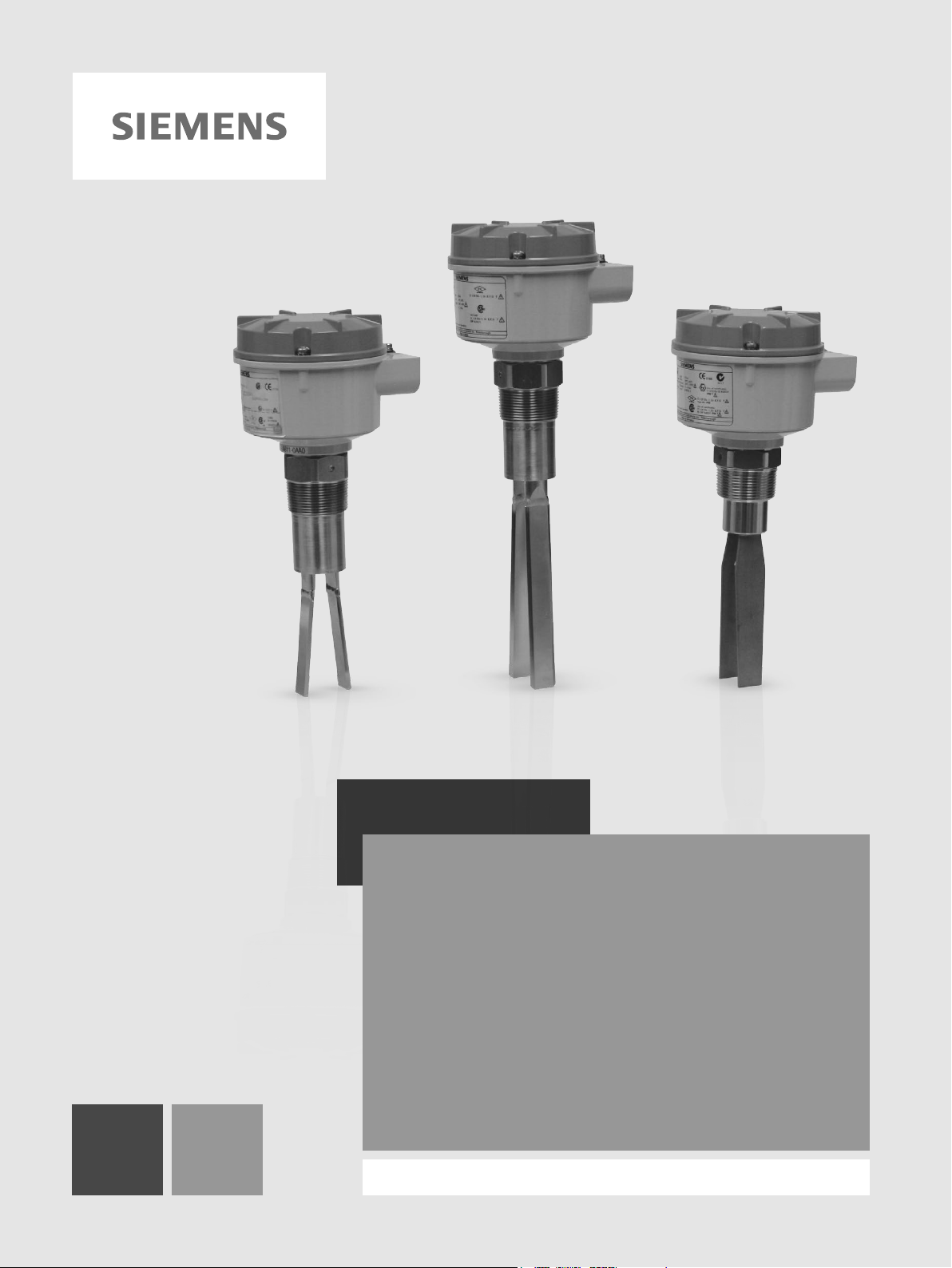
SITRANS L
Point Level Switches
SITRANS LVS100/200
Operating Instructions
7ML5735 (SITRANS LVS100 Standard)
7ML5731 (SITRANS LVS200 Standard)
7ML5732 (SITRANS LVS200 Short fork)
7ML5733 (SITRANS LVS200 Pipe extension)
7ML5734 (SITRANS LVS200 Cable extended)
01/2019
A5E44839609
Introduction
1
Description
2
Operating
3
Installation
4
Connecting
5
Maintenance
6
Technical data
7
Dimension drawings
8
Certificates and support
A
-AA
Siemens AG
Division Process Industries and Drives
Postfach 48 48
90026 NÜRNBERG
GERMANY
Document order number: A5E44839609
Ⓟ
Copyright © Siemens AG 2012.
All rights reserved
Legal information
Warning notice system
DANGER
indicates that death or severe personal injury will result if proper precautions are not taken.
WARNING
indicates that death or severe personal injury may result if proper precautions are not taken.
CAUTION
indicates that minor personal injury can result if proper precautions are not taken.
NOTICE
indicates that property damage can result if proper precautions are not taken.
Qualified Personnel
personnel qualified
Proper use of Siemens products
WARNING
Siemens products may only be used for the applications described in the catalog and in the relevant technical
ambient conditions must be complied with. The information in the relevant documentation must be observed.
Trademarks
Disclaimer of Liability
This manual contains notices you have to observe in order to ensure your personal safety, as well as to prevent
damage to property. The notices referring to your personal safety are highlighted in the manual by a safety alert
symbol, notices referring only to property damage have no safety alert symbol. These notices shown below are
graded according to the degree of danger.
If more than one degree of danger is present, the warning notice representing the highest degree of danger will
be used. A notice warning of injury to persons with a safety alert symbol may also include a warning relating to
property damage.
The product/system described in this documentation may be operated only by
task in accordance with the relevant documentation, in particular its warning notices and safety instructions.
Qualified personnel are those who, based on their training and experience, are capable of identifying risks and
avoiding potential hazards when working with these products/systems.
Note the following:
for the specific
documentation. If products and components from other manufacturers are used, these must be recommended
or approved by Siemens. Proper transport, storage, installation, assembly, commissioning, operation and
maintenance are required to ensure that the products operate safely and without any problems. The permissible
All names identified by ® are registered trademarks of Siemens AG. The remaining trademarks in this publication
may be trademarks whose use by third parties for their own purposes could violate the rights of the owner.
We have reviewed the contents of this publication to ensure consistency with the hardware and software
described. Since variance cannot be precluded entirely, we cannot guarantee full consistency. However, the
information in this publication is reviewed regularly and any necessary corrections are included in subsequent
editions.
01/2019 Subject to change

Table of contents
1 Introduction ................................................................................................................................................ 5
2 Description ................................................................................................................................................. 6
3 Operating ................................................................................................................................................... 9
4 Installation ............................................................................................................................................... 14
5 Connecting .............................................................................................................................................. 20
6 Maintenance ............................................................................................................................................ 37
1.1 Purpose of this documentation ................................................................................................. 5
2.1 SITRANS LVS100, SITRANS LVS200 - standard version ....................................................... 6
2.2 SITRANS LVS200 - liquid/solid interface version ..................................................................... 6
2.3 SITRANS LVS200 - pipe extension version ............................................................................. 6
2.4 Product features ........................................................................................................................ 7
2.5 Product applications.................................................................................................................. 7
2.6 Principle of operation ................................................................................................................ 7
3.1 Signal output delay ................................................................................................................... 9
3.2 Test function ............................................................................................................................. 9
3.3 Vibration amplitude diagnosis ................................................................................................. 12
3.4 Current output setting ............................................................................................................. 12
3.5 Buildup detection (8/16 mA or 4 to 20 mA version) ................................................................ 13
4.1 Mounting ................................................................................................................................. 14
4.2 Process cautions ..................................................................................................................... 17
4.3 Temperature isolator option (LVS100/200) ............................................................................ 18
5.1 Connection recommendations ................................................................................................ 21
5.2 Precautions ............................................................................................................................. 21
5.3 Power supply specifications .................................................................................................... 26
5.4 Sensitivity ................................................................................................................................ 27
5.5 Switching logic ........................................................................................................................ 28
5.6 SITRANS LVS200 Pipe extension version ............................................................................. 30
5.6.1 Extension tube manufacture ................................................................................................... 30
5.6.2 Extension tube dimensions ..................................................................................................... 31
5.6.3 Assembly ................................................................................................................................ 33
5.6.4 Assembly overview drawing ................................................................................................... 36
6.1 Unit repair and excluded liability ............................................................................................. 37
SITRANS LVS100/200
Operating Instructions, 01/2019, A5E44839609-AA
3

Table of contents
7 Technical data ......................................................................................................................................... 38
8 Dimension drawings ................................................................................................................................ 42
A Certificates and support ........................................................................................................................... 47
Index ........................................................................................................................................................ 48
8.1 SITRANS LVS100 .................................................................................................................. 42
8.2 Zone classification ................................................................................................................. 43
8.3 SITRANS LVS200 .................................................................................................................. 44
8.4 Zone classification ................................................................................................................. 45
8.5 SITRANS LVS200 Forks ........................................................................................................ 46
A.1 Technical support ................................................................................................................... 47
A.2 Certificates ............................................................................................................................. 47
SITRANS LVS100/200
4 Operating Instructions, 01/2019, A5E44839609-AA

1
1.1
Purpose of this documentation
Note
•
•
•
These instructions contain all information required to commission and use the device. Read
the instructions carefully prior to installation and commissioning. In order to use the device
correctly, first review its principle of operation.
The instructions are aimed at persons mechanically installing the device, connecting it
electronically, configuring the parameters and commissioning it, as well as service and
maintenance engineers.
This manual applies to SITRANS LVS100 and SITRANS LVS200 only.
Product details and instructions in this manual relate to both SITRANS LVS100 and
SITRANS LVS200 unless otherwise stated.
This product is intended for use in industrial areas. Operation of this equipment in a
residential area can cause interference to several frequency based communications.
SITRANS LVS100/200
Operating Instructions, 01/2019, A5E44839609-AA
5

2
2.1
SITRANS LVS100, SITRANS LVS200 - standard version
2.2
SITRANS LVS200 - liquid/solid interface version
2.3
SITRANS LVS200 - pipe extension version
The SITRANS LVS100 and SITRANS LVS200 are available in a standard version, with the
SITRANS LVS200 offering two additional versions.
SITRANS LVS100/200 standard version is a vibrating level switch that detects high or low
levels of dry bulk solids in bins, silos, or hoppers. It has a compact design that allows it to be
top or side mounted and the vibrating fork ensures that the tines are kept clean.
● SITRANS LVS100 is an entry level solids fork with a bulk density limit starting at 30 g/l
(3.8 lb/ft
● SITRANS LVS200 provides several output options for indication of point level with
products such as lime, styrofoam, flour, and plastic granules, starting at 20 g/l (1.2 lb/ft
It handles a broader range of applications and is able to measure bulk densities of less
than 5g/l. In addition, the LVS200 has a wider range of process configurations. SITRANS
LVS200 standard length fork is available with variable cable extension lengths to a
maximum of 20 000 mm (787") (cable extensions for top mount applications only). An
optional longer fork is available for increased sensitivity.
The SITRANS LVS200, liquid/solid interface version, is a vibrating level switch that can also
detect settled solids within liquids, or solids within confined spaces such as feed pipes. This
version is designed to ignore liquids in order to detect the interface between a solid and a
liquid. The design incorporates a short fork, and is also available with variable cable
extension lengths to a maximum of 7000 mm (275.59"), for top mount applications only.
3
). The LVS100 is available with rigid extension options to 4 000 mm (157").
3
).
The SITRANS LVS200, pipe extension version, is a vibrating level switch that incorporates a
customer supplied pipe extension [maximum length 3800 mm (150")] with the standard or
liquid/solid (short) LVS200 fork and electronics. This allows for separation of the electronics
and tuning fork for applications requiring a rigid extension. See SITRANS LVS200 Pipe
Extended Version (Page 30) for information on assembly.
SITRANS LVS100/200
6 Operating Instructions, 01/2019, A5E44839609-AA
Description
2.4
Product features
LVS200 standard version
20 g/l (1.2 lb/ft 3) min.
LVS200 liquid/solid interface version
50 g/l (3.0 lb/ft 3) min.
2.5
Product applications
2.6
Principle of operation
WARNING
Do not use as a safety device
2.4 Product features
● High resistance to mechanical forces
● Strong vibration resistance to high bulk material loads
● Rotatable enclosure
● LVS100: R 1½" (BSPT); 1¼" NPT (Taper) threaded connection
● LVS200: Stainless steel 1½” NPT or R 1½” (BSPT) threaded connection, or R 2" (BSPT)
or NPT sliding sleeve. DN 100 and 2, 3, 4" ASME flange and Triclamp 2" options
available.
● Suitable for high or low density material
LVS100 standard version 30 g/l (1.9 lb/ft 3) min.
LVS200 standard version with low density fork 5 g/l (0.3 lb/ft 3) min.
● Dry lime, Styrofoam, flour, plastic granules
● High or low density, dry bulk materials
● Interface detection of a solid within a liquid (filter beds)
● Flow or no flow detection in pipe using liquid/solid LVS200 version
A signal from the electronic circuit excites a crystal in the probe, causing the fork to vibrate. If
the fork is covered by material, the change in vibration is detected by electronic circuitry
which causes the relay to change state after a one second delay. When the material no
longer reaches the tines, full vibration resumes and the relay reverts to its normal state.
This product is designed as a Pressure Accessory per Directive 2014/68/EU and is not
intended for use as a safety device.
SITRANS LVS100/200
Operating Instructions, 01/2019, A5E44839609-AA
7
Description
WARNING
Chemical compatibility
general purposes. For exposure to specific environments, check with chemical compatibility
2.6 Principle of operation
Materials of construction are chosen based on their chemical compatibility (or inertness) for
charts before installing.
SITRANS LVS100/200
8 Operating Instructions, 01/2019, A5E44839609-AA
3
Note
The signal output and test options listed below apply only to specific power supply options.
3.1
Signal output delay
Universal voltage (DPDT) model
3.2
Test function
NAMUR model (IEC 60947-5-6) and 8/16 mA or 4 to 20 mA model
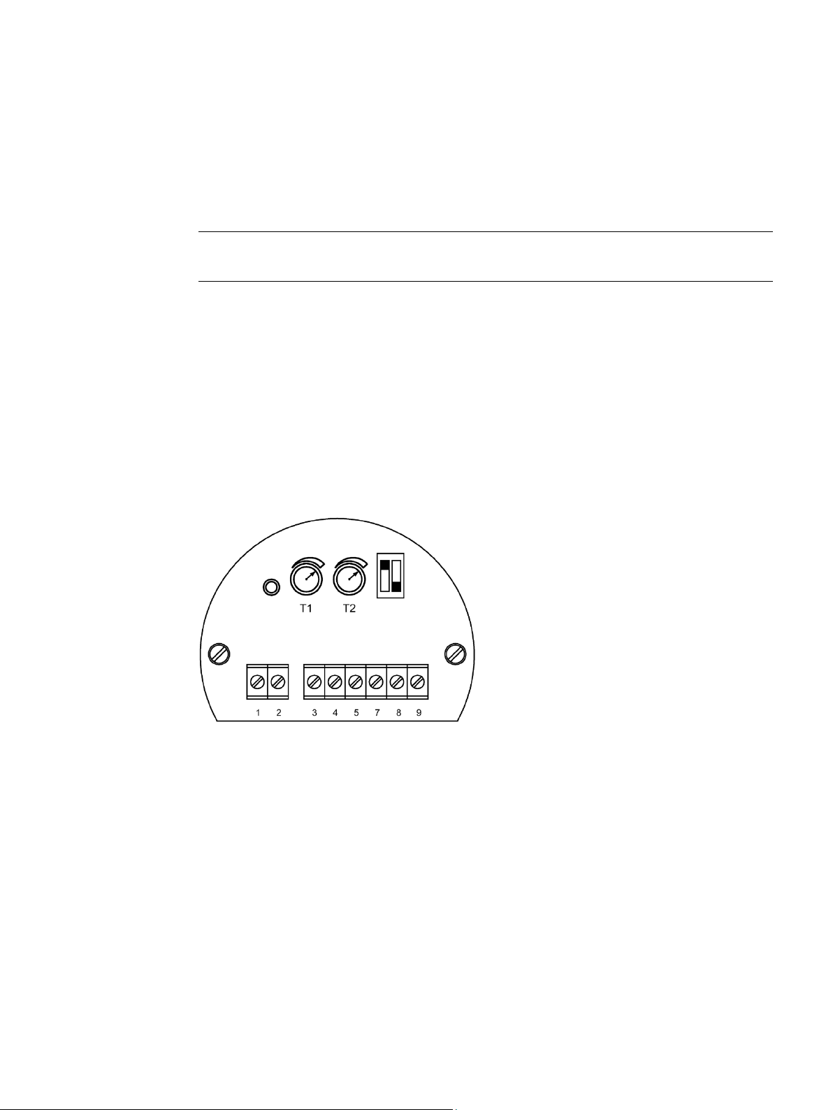
The signal output can be delayed and is adjustable from 0 to 30 seconds. Turn the
potentiometer clockwise to increase the delay time.
Potentiometer T1: Delay when output switches from fork covered to uncovered.
Potentiometer T2: Delay when output switches from fork uncovered to covered.
If the fork is uncovered, pressing this button will stop the vibration and the signal output will
switch to indicate a covered fork. You can test the vibration and the electronics without
removing the LVS200 from the vessel. If the fork is covered, pressing the button has no
effect.
SITRANS LVS100/200
Operating Instructions, 01/2019, A5E44839609-AA
9

Operating
NAMUR model
①
Test button
②
Electronic module
③
Diagnostic LED
④
A = decreased sensitivity
3.2 Test function
Sensitivity adjustment:
B = factory setting
SITRANS LVS100/200
10 Operating Instructions, 01/2019, A5E44839609-AA
Operating
8/16 or 4 to 20 mA model
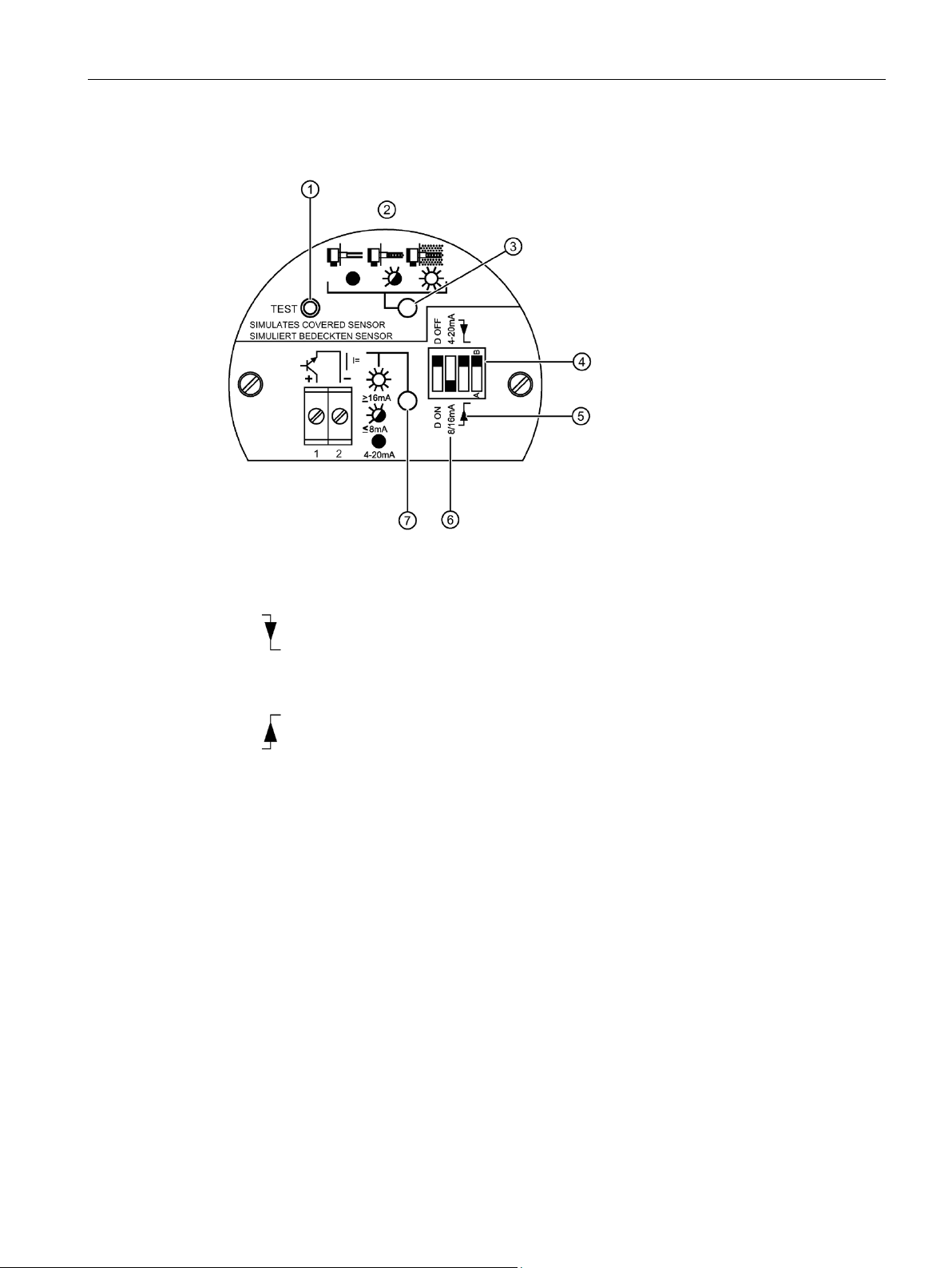
①
Test button
②
③
Diagnostic LED
④
A = decreased sensitivity
⑤
Filling or emptying
⑥
Output setting
⑦
Signal output LED
3.2 Test function
Sensor switches at high level
Fail-safe function will default to full signal
Sensor switches at low level
Fail-safe function will default to empty signal
Sensitivity adjustment:
B = factory setting
SITRANS LVS100/200
Operating Instructions, 01/2019, A5E44839609-AA
11
Operating
3.3
Vibration amplitude diagnosis
NAMUR module (IEC 60947-5-6) and 8/16 mA or 4 to 20 mA model
3.4
Current output setting
8/16 mA
ting
D Off
I = 16 mA
I = 8 mA
D ON.
D OFF
D ON
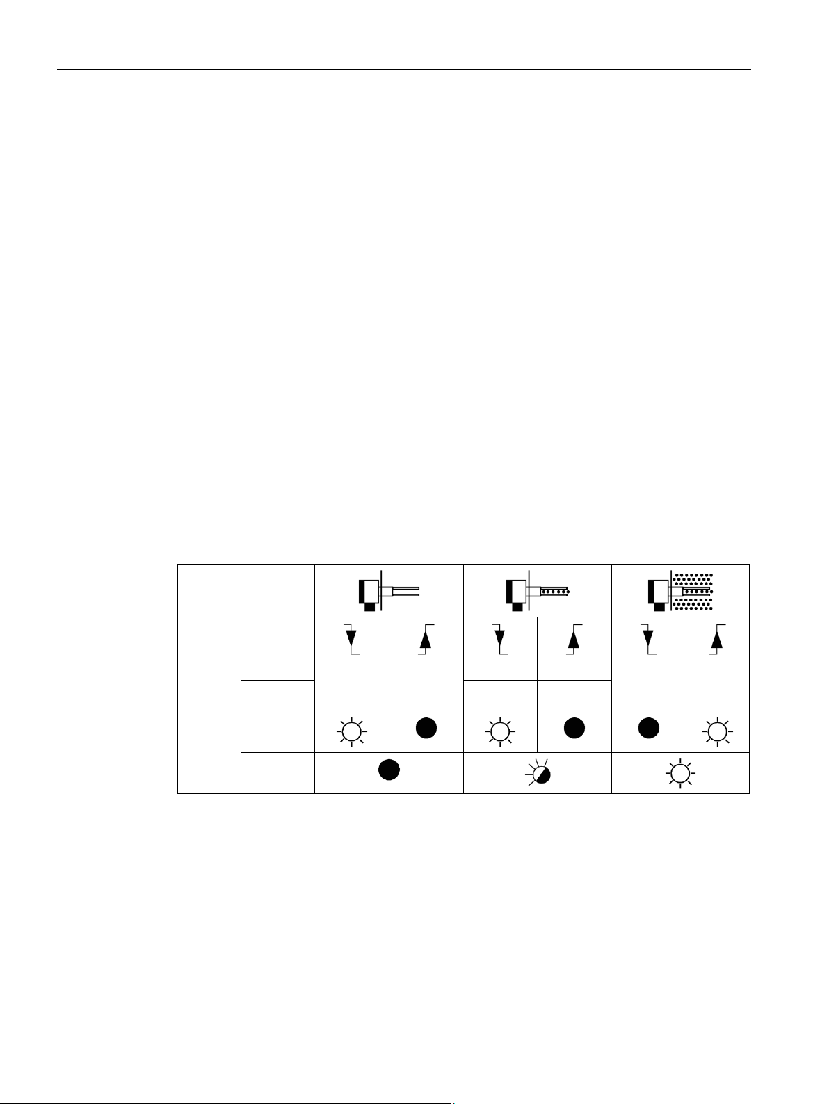
3.3 Vibration amplitude diagnosis
Measurement quality is related to the vibration amplitude of the fork. The diagnostic LED
indicates the quality of the vibration being sent to the LVS200 electronics.
● Diagnostic LED off: measurement quality is good. The vibration amplitude is strong.
● Diagnostic LED blinking: measurement quality is poor and vibration amplitude is
decreasing as fork becomes encrusted. When this happens, set the sensitivity switch to
decreased sensitivity.
● Diagnostic LED on: vibration has stopped and fork is fully encrusted with material.
The chart below illustrates the output current when:
● Fork is clean
● Fork is encrusted: weak vibration amplitude is shown
● Fork is fully encrusted and vibration has stopped.
Diagno-
sis Set-
Signal
D On I = 20 mA I = 6 mA
output LED
Diagnosis
LED
The output current can indicate weak vibration amplitude with the diagnosis setting
the diagnosis is set to
I = 16 mA I = 8 mA
, the output will be either 8 mA or 16 mA depending on high or
I = 8 mA I = 16
mA
If
low level settings.
If the diagnosis is set to
, the output will change from 16 to 20 mA and from 8 to 6 mA if
the vibration is weak. This output can be passed to an external 4 to 20 mA output. There is
an internal delay of 10 seconds before the change happens, so that the external output does
not indicate a weak vibration when the vibration is stopped and started during normal
measurement operation.
SITRANS LVS100/200
12 Operating Instructions, 01/2019, A5E44839609-AA
Operating
3.5
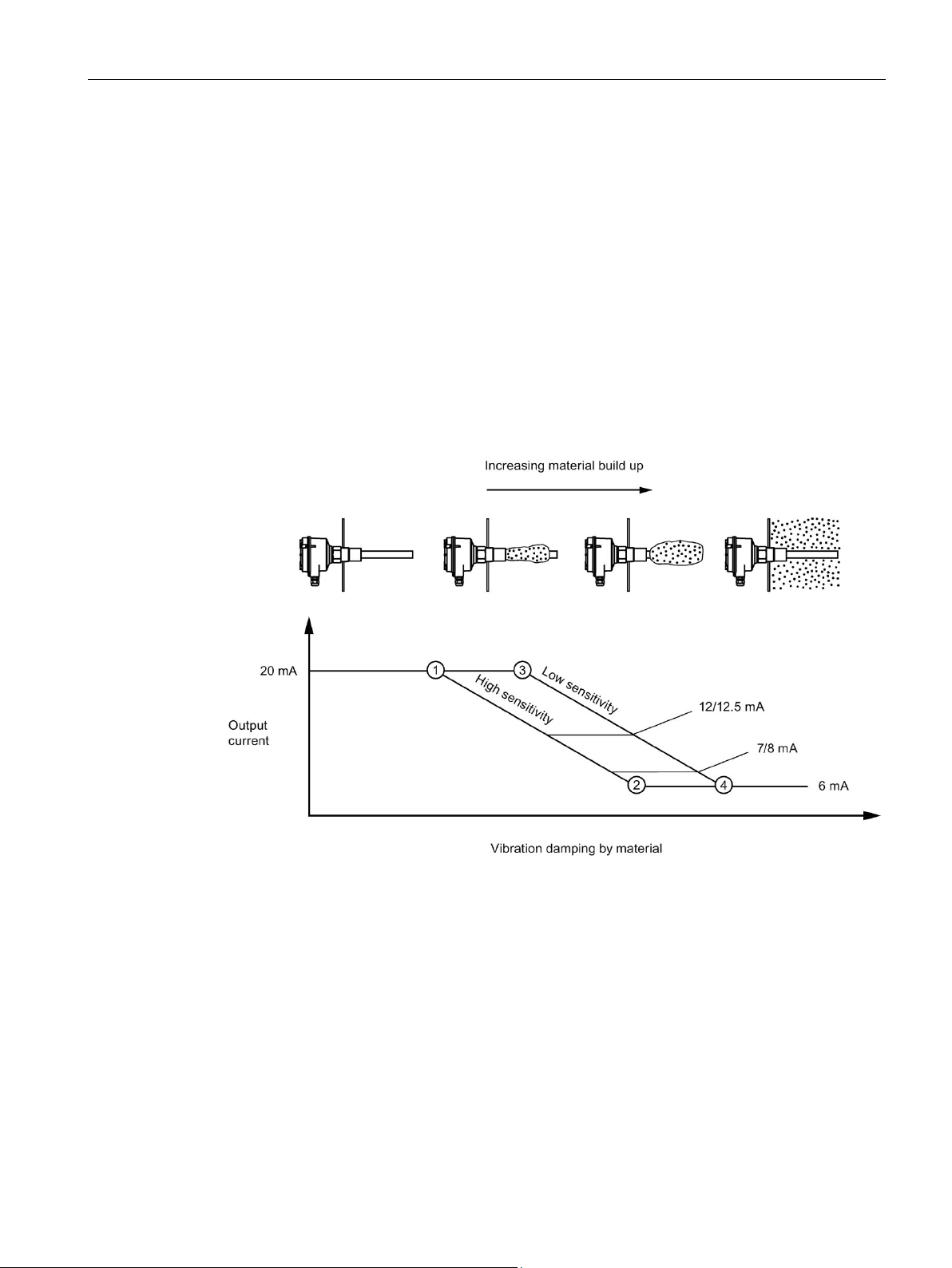
Buildup detection (8/16 mA or 4 to 20 mA version)
20 mA:
<20 mA and >12/12.5 mA:
<12/12.5 mA and >7/8 mA:
7/8 mA:
6 mA:
With setting "high sensitivity"
With setting "low sensitivity"
①
Amplitude is 100%
③
Amplitude is 100%
②
Amplitude is 0%
④
Amplitude is 0%
3.5 Buildup detection (8/16 mA or 4 to 20 mA version)
With the 4 to 20 mA setting, you can recognize material buildup on the fork using a PLC or
data logger. In this mode, the Diagnostic setting has no influence. The LED showing signal
output is off.
●
●
●
showing diagnosis begins blinking to indicate a weak signal. If you are using a PLC to
evaluate the echo, delay the response time to this indicator for approximately 10
seconds. A hysteresis of 0.5 mA (between 12 and 12.5 mA) is recommended.
●
●
The fork is clean.
The vibration amplitude is decreased by the material buildup.
This range indicates a weak vibration. The internal LED
This point indicates that the fork is mostly encrusted.
This point indicates that the fork is fully encrusted.
SITRANS LVS100/200
Operating Instructions, 01/2019, A5E44839609-AA
13
4
4.1
Mounting
WARNING
LVS100 and LVS200
This product is designated as a Pressure Accessory per Directive 2014/68/EU and is not
● Installation shall be performed by qualified personnel and in accordance with local
governing regulations.
● Do not bend, shorten or extend the tines.
● Position the tines using a 50 mm open-end wrench when installing the process
connection (do not turn the housing). When side mounting SITRANS LVS100/200,
position the tines vertically, with the tine orientation marking facing up or down.
● In pressure applications, use PTFE tape or other appropriate sealant to seal tapered
threaded connections.
● After mounting, ensure the cable entries point downward to prevent water entering the
housing.
● For the SITRANS LVS100/200 extended model, the torque due to material loading at the
mounting point may not exceed 250 Nm.
● Mounting torque for the 1½" thread connection may not exceed 80 Nm.
•
intended for use as a safety device.
• Improper installation may result in loss of process pressure.
• To install devices in hazardous locations, observe all valid installation regulations.
• For Dust Ex installations: Before opening the device lid, ensure there are no deposits
present.
• Do not remove lid while circuits are live.
• Install the SITRANS LVS100/200 so mechanical friction or impact does not cause
sparks between the aluminum enclosure and steel vessel.
SITRANS LVS100/200
14 Operating Instructions, 01/2019, A5E44839609-AA
 Loading...