

Siemens LVM Installation Instructions Manual
Installation Instruct ions
Model LVM
Live Voice Module
INTRODUCTION The Model LVM Live Voice Module from Siemens
Industry, Inc. provides firefighters with a means of
sending live voice messages to specified audio
zones. The LVM has a push-to-talk switch on the
microphone, as well as a retractable coiled cord.
Both the push-to talk switch and the microphone
are supervised. The LVM has a built-in speaker to
preview active tones and messages. Each DACNET in the system (with an LPB) supports up to
five LVMs. Additional LVMs may be
connected remotely using the RNI.
OPERATION
Controls and Indicators The front panel of the LVM contains
six switches and six pairs of LEDS.
Each pair contains one bi-color (red/
green) and one yellow LED. The
functions of the switches and LEDs
are programmed using the Zeus Tool
(Refer to the Zeus Quick Start Guide,
P/N 315-033875). All LEDs can be
programmed ON, OFF, or FLASHING.
These switches are used for manual
control of the voice system.
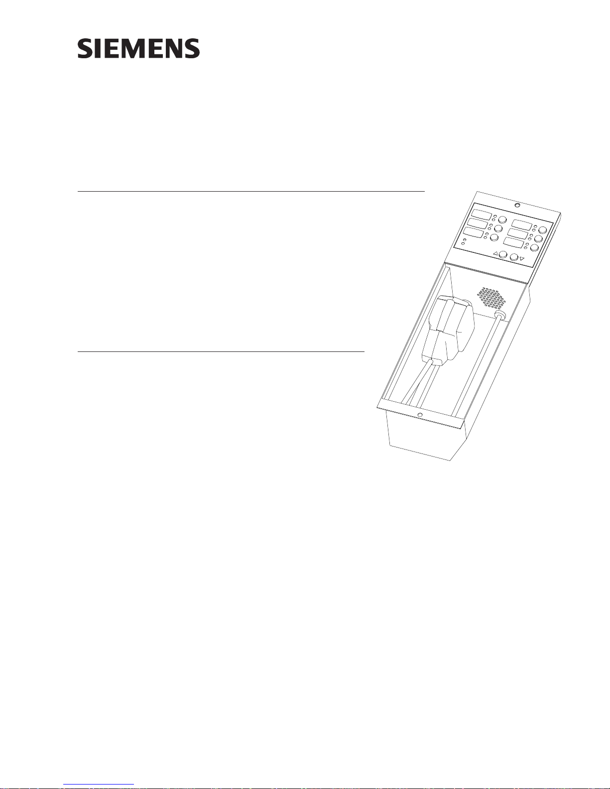
Figure 1
LVM Live Voice Module
The functions of the remaining LEDs and push buttons are defined as follows:
PREANNOUNCE TONE (Yellow) When illuminated, indicates that the
READY TO PAGE (Green) When illuminated, indicates that all
MONITOR VOLUME These two pushbuttons increase or
P/N 315-034090-11
preannounce tone is active at the
speakers.
selected zones are ready to be paged.
decrease the volume of the speaker on
the LVM.
Building Building
Building
Building Building
Siemens Siemens
Siemens
Siemens Siemens
TT
ecec
hnologies Dihnologies Di
T
ec
hnologies Di
TT
ecec
hnologies Dihnologies Di
IndustryIndustry
Industry
IndustryIndustry
visionvision
vision
visionvision
,,
Inc. Inc.
,
Inc.
,,
Inc. Inc.
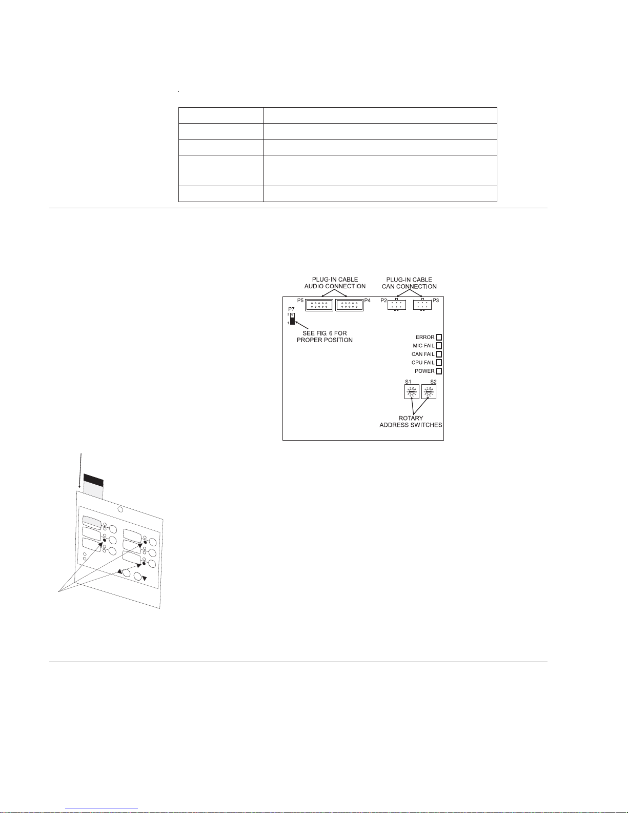
The back of the LVM contains 2 rotary address switches and five diagnostic LEDs,
two plug-in cable connectors for the CAN and two plug-in cable connectors for audio.
(See Figure 2). The function of the diagnostic LEDs are defined as follows:
SCITSONGAIDMVLFONOITPIRCSED
RORRE.ylnoesuyrotcaF
LIAFCIM .detcetedsienohporcimehtfoeruliafanehwydaetsswolgDEL
LIAFNAC .detcetedsikrowt
LIAFUPC.detcetedsiUPCehtfoeruliafanehwydaetsswolgDEL
.wolleythgil
REWOP.NOsiMVLehtrofrewopehtnehwydaetsswolgDEL
enNACehtnoeruliafanehwydaetsswolgDEL
acidnisDELesuacoslalliwnoitidnocliaFUPCehT*
ot3erugiFnidet
PRE-INSTALLATION Set the board address for the LVM using both of the ten-position rotary switches
located on the back of the board (See Figure 2). Each of these addresses must be a
sub-address of the DAC and must be the same as the addresses assigned in the
Zeus Programming Tool.
Figure 2
LVM Cable Connections, Diagnostics and Address Switches
After setting the address, label each switch or LED. When viewed from the front
panel of the LVM, the labels are on the left and the control switches and LEDs are on
the right.
• Refer to the Zeus configuration for the address of each module and its
assigned functions.
• Remove the label strip from its slot, and type or print a brief function
identifier for each switch.
*
• After completing the label strip, insert in back into its slot (See Figure 3).
Figure 3
Inserting A Label Into
The Back Of The LVM
INSTALLATION The LVM mounts to the rear of the inner door in the CAB-1, CAB-2, CAB-3, REMBOX2
or REMBOX4 enclosures. Select the location of the LVM. In CAB-1/-2/-3 it can be
mounted on either side of the PMI/PMI-2, over the two mounting studs in the
desired location. In the REMBOX2/4 the LVM may mount in any of the positions (as
viewed from the front). Secure the LVM to the inner door with the two nuts provided.
(Refer to Figure 4.)
Siemens Industry, Inc.
Building Technologies Division
P/N 315-034090-112
 Loading...