

Siemens LU-180, Sitrans LU-180 Operating Instructions Manual
Ultrasonic Transmitters
LU-180 (Sitrans LU-180)
Operating Instructions
Edition 06/2016

SITRANS LU180
___________________
___________________
___________________
___________________
___________________
___________________
___________________
___________________
___________________
Ultrasonic Transmitters
SITRANS LU180
Operating Instructions
06/2016
A5E37100674
-AA
Introduction
1
Description
2
Installing and mounting
3
Connecting
4
Commissioning
5
Operating
6
Troubleshooting
7
Technical data
8
Appendix
A
Siemens AG
Division Process Industries and Drives
Postfach 48 48
90026 NÜRNBERG
GERMANY
Document order number: A5E37100674
Ⓟ
03/2016 Subject to change
Copyright © Siemens AG 2016.
All rights reserved
Legal information
Warning notice system
This manual contains notices you have to observe in order to ensure your personal safety, as well as to prevent
damage to property. The notices ref er ring to your personal safety are highlighted in t he manual by a safety alert
symbol, notices referring only to property damage have no safety alert symbol. These notices shown below are
graded according to the degree of danger.
DANGER
indicates that death or severe pers onal injury will result if proper precautions are not t ak en.
WARNING
indicates that death or severe pers onal injury may result if proper precautions are not taken.
CAUTION
indicates that minor personal inj ur y can result if proper precautions are not tak en.
NOTICE
indicates that property damage can r es ult if proper precautions are not taken.
If more than one degree of danger is present, the warning notice representing the hig hes t degree of danger will be
used. A notice warning of injury to persons with a safety alert symbol may also include a warning relating to property
damage.
Qualified Personnel
The product/system described in this documentation may be operated only by
personnel qualified
for the specific task
in accordance with the relevant doc um entation, in particular its warning no tices and safety instructions. Qualified
personnel are those who, based on thei r training and experience, are capable of identifying risks and avoiding
potential hazards when working with these products/systems.
Proper use of Siemens products
Note the following:
WARNING
Siemens products may only be used for the applications described in the catal og and in the relevant technical
documentation. If products and components from other manufacturers are used, these must be recommended
or approved by Siemens. Proper tr ansport, storage, installation, assembly, commissioning, operation and
maintenance are required to ensure t hat the products operate safely and without any problems. The permissible
ambient conditions must be complied with. The information in the relevant documentation must be observed.
Trademarks
All names identified by ® are registered trademarks of Siemens AG. The remaining trademarks in this publication may
be trademarks whose use by third part i es for their own purposes could violate the rights of the owner.
Disclaimer of Liability
We have reviewed the contents of this publication to ensure consistency with the hardware and software described.
Since variance cannot be precluded entirely, we cannot guarantee full consistency. However, the information in this
publication is reviewed regula rly and any necessary corrections are include d i n s ubsequent editions.

SITRANS LU180
Operating Instructions, 06/2016, A5E37100674-AA
3
Table of contents
1 Introduction ................................................................................................................................................ 5
2 Description ................................................................................................................................................. 7
3 Installing and mounting .............................................................................................................................. 9
3.1 Environmental ........................................................................................................................... 9
3.2 Location .................................................................................................................................... 9
3.3 Threaded ................................................................................................................................. 10
3.4 Flange adapter (optional) ........................................................................................................ 11
3.5 4" Sanitary ............................................................................................................................... 12
3.6 LU180 with FMS200 mounting bracket................................................................................... 15
4 Connecting .............................................................................................................................................. 17
4.1 Connecting the LU180 ............................................................................................................ 17
4.1.1 Cable entry .............................................................................................................................. 17
4.1.2 System diagram ...................................................................................................................... 18
4.1.3 Wiring connection ................................................................................................................... 18
4.2 Instructions specific to hazardous area installations .............................................................. 19
4.3 Nameplates for hazardous area installations ......................................................................... 20
5 Commissioning ........................................................................................................................................ 23
5.1 Start up ................................................................................................................................... 23
5.2 Calibration ............................................................................................................................... 24
5.3 Calibration: reference method ................................................................................................ 24
5.4 4 mA calibration ...................................................................................................................... 25
5.5 20 mA calibration .................................................................................................................... 25
5.6 Operation status ...................................................................................................................... 26
6 Operating ................................................................................................................................................. 27
6.1 Adjustments ............................................................................................................................ 27
6.2 Calibration, scrolling method .................................................................................................. 28
6.3 4 mA calibration ...................................................................................................................... 28
6.4 20 mA calibration .................................................................................................................... 29
6.5 Blanking .................................................................................................................................. 29
6.6 Adjusting the blanking value ................................................................................................... 30
6.7 Speed of response .................................................................................................................. 30
6.8 Adjusting the speed of response ............................................................................................ 31

Table of contents
SITRANS LU180
4 Operating Instructions, 06/2016, A5E37100674-AA
6.9 Fail-safe ................................................................................................................................. 32
6.10 Adjusting the fail-safe setting ................................................................................................. 32
6.11 Fail-safe timer ........................................................................................................................ 33
6.12 Adjusting the fail-safe timer .................................................................................................... 33
6.13 Units ....................................................................................................................................... 33
6.14 Adjusting the units .................................................................................................................. 34
7 Troubleshooting ....................................................................................................................................... 35
8 Technical data ......................................................................................................................................... 37
8.1 Power ..................................................................................................................................... 37
8.2 Performance ........................................................................................................................... 37
8.3 Interface ................................................................................................................................. 37
8.4 Outputs ................................................................................................................................... 38
8.5 Construction ........................................................................................................................... 38
8.6 Operating conditions .............................................................................................................. 38
8.7 Approvals ............................................................................................................................... 39
A Appendix .................................................................................................................................................. 41
A.1 Measurement interval ............................................................................................................ 41

SITRANS LU180
Operating Instructions, 06/2016, A5E37100674-AA
5
1
Note
For industrial use only
This product is intended for use in industrial areas. Operation of this equipment in a
residential area may cause interference to several frequency based communications.
Note
Unit repair
All changes and repairs must be done by qualified per sonnel, and applicable safety
regulations must be followed. Please note the following:
•
The user is responsible for all changes and repairs made to the device.
•
All new components must be provided by Siemens.
•
Restrict repair to faulty components only.
•
Do not re-use faulty components.

Introduction
SITRANS LU180
6 Operating Instructions, 06/2016, A5E37100674-AA

SITRANS LU180
Operating Instructions, 06/2016, A5E37100674-AA
7
2
The SITRANS LU180 is an ultrasonic level monitor combining sensor and electronics in a single
package. It is designed to measure liquid levels in open or closed vessels. The process part
(sensor) is PVDF, allowing the SITRANS LU180 t o be used in a wide variety of industries,
especially food and chemical.
The sensor houses the ultrasonic transducer and temperature sensing element. The SITRANS
LU180 emits a series of ultrasonic pulses from the transducer. Each pulse is reflected as an
echo from the material and sensed by the transduce r. T he echo is processed by the SITRANS
LU180 using Siemens' proven ‘Sonic Intelligence’ techniques. Filtering is applied to help
discriminate between the true echo from the material, and false echoes from acoustical and
electrical noises and agitator blades in motion. The t i m e for the pulse to travel to the material
and back is temperature compensated and then converted into distance for the mA output.

Description
SITRANS LU180
8 Operating Instructions, 06/2016, A5E37100674-AA
SITRANS LU180
Operating Instructions, 06/2016, A5E37100674-AA
9
3
3.1
Environmental
The SITRANS LU180 should be mounted in an area that is wit hi n the temperature range
specified, and that is suitable to the housing rating and materials of construction.
It is advisable to keep the device away from high volta ge or current runs, contactors and SCR
control drives.
3.2
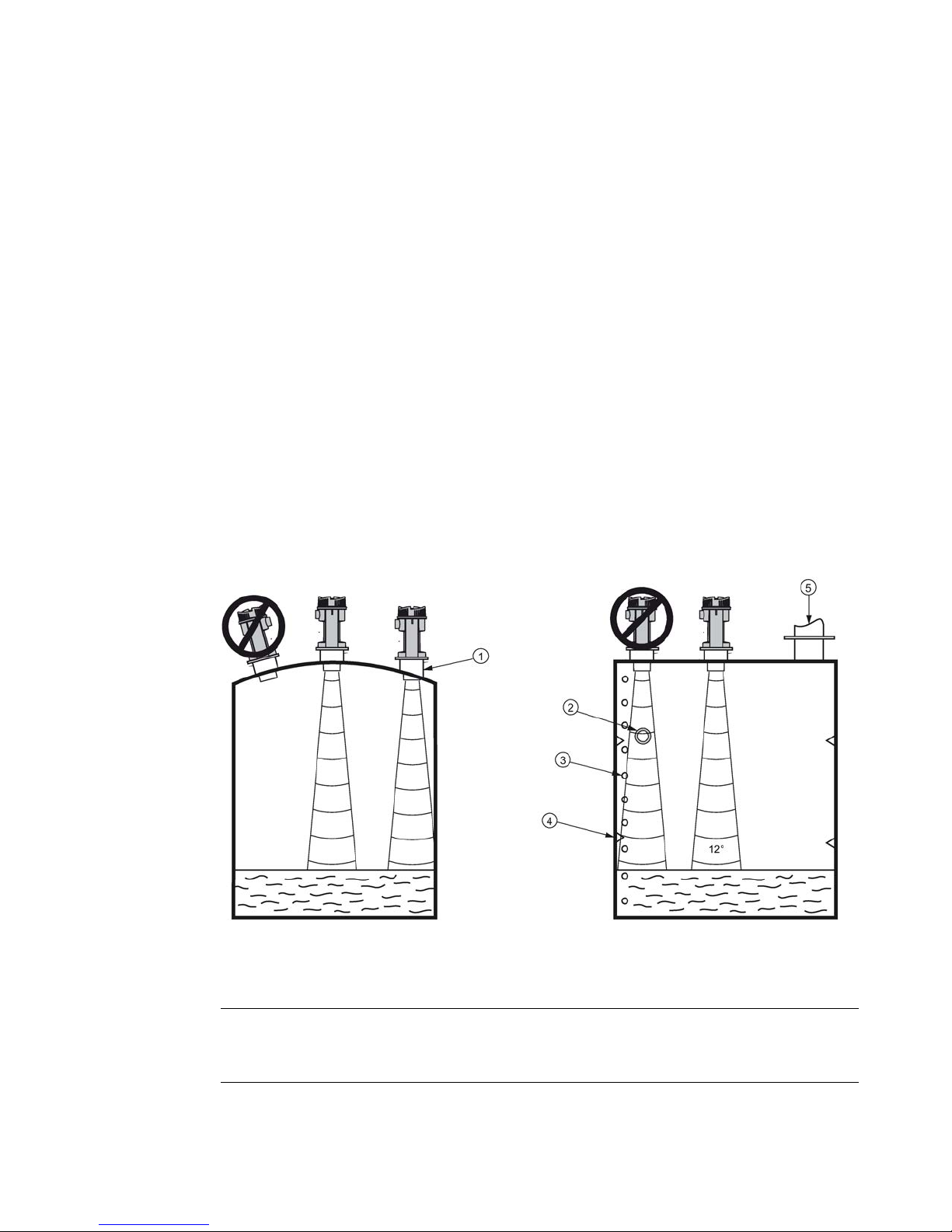
Location
Locate the SITRANS LU180 so that it
will have a clear sound path that is
perpendicular to the liquid surface.
The SITRANS LU180 sound path should
not intersect the fill path, rough walls,
seams, rungs, etc.
①
Sanitary ferrule
④
Seams
②
Pipe
⑤
Fill ③ Rungs
Note
Mount the SITRANS LU180 so that the face of the senso r i s at l east 25 cm above the
highest anticipated level.
Installing and mounting
3.3 Threaded
SITRANS LU180
10 Operating Instructions, 06/2016, A5E37100674-AA
3.3
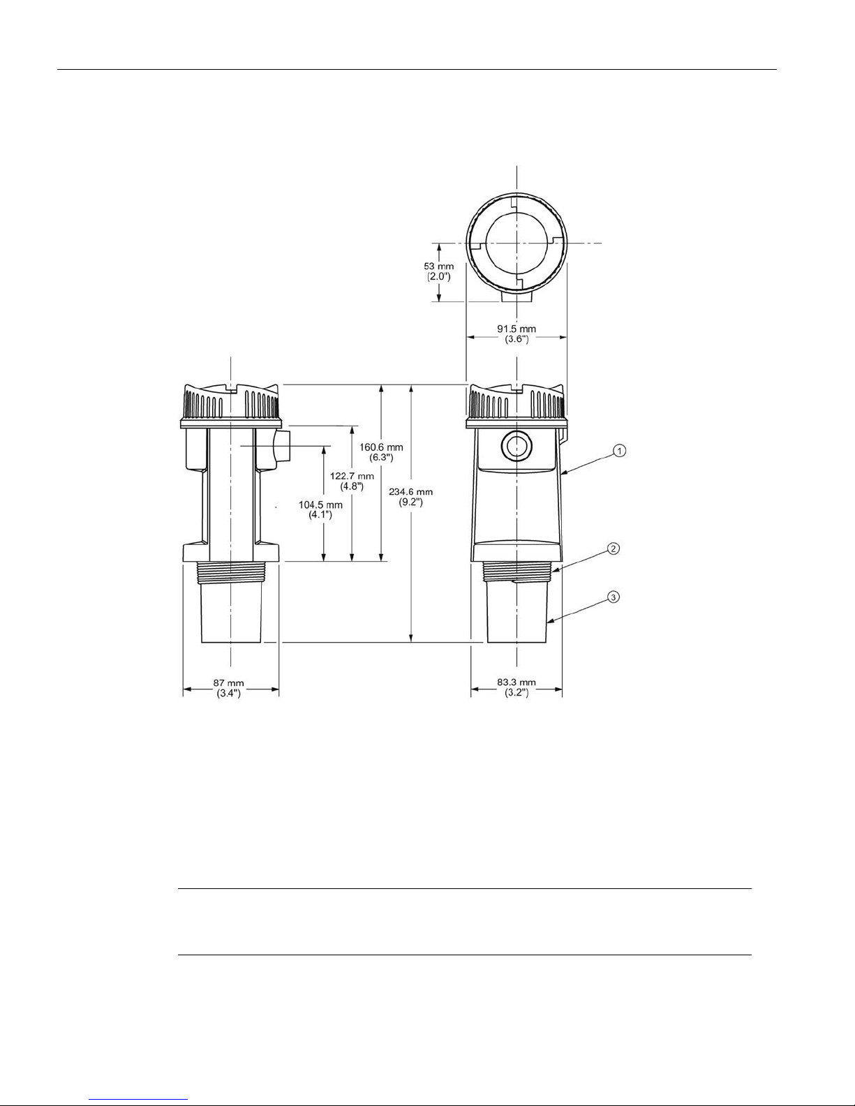
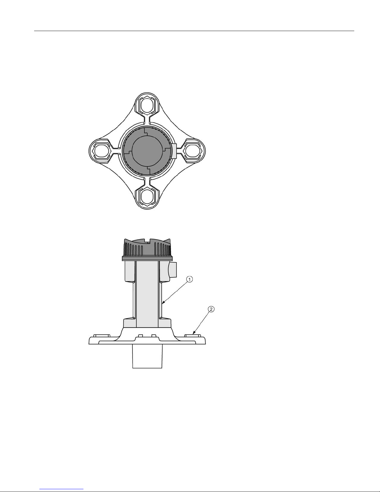
Threaded
①
Electronics
②
Mounting thread
③
Sensor
The SITRANS LU180 is available in three thread typ es:
1. 2" NPT ((Taper), ANSI/ASME B1.20.1)
2. R 2" ((BSPT), EN 10226)
3. G 2" ((BSPP), EN ISO 228-1
Note
Before inserting the SITRANS LU180 into its mounting hole, ensure that the threads are of
the same type to avoid damaging the device.
Installing and mounting
3.4 Flange adapter (optional)
SITRANS LU180
Operating Instructions, 06/2016, A5E37100674-AA
11
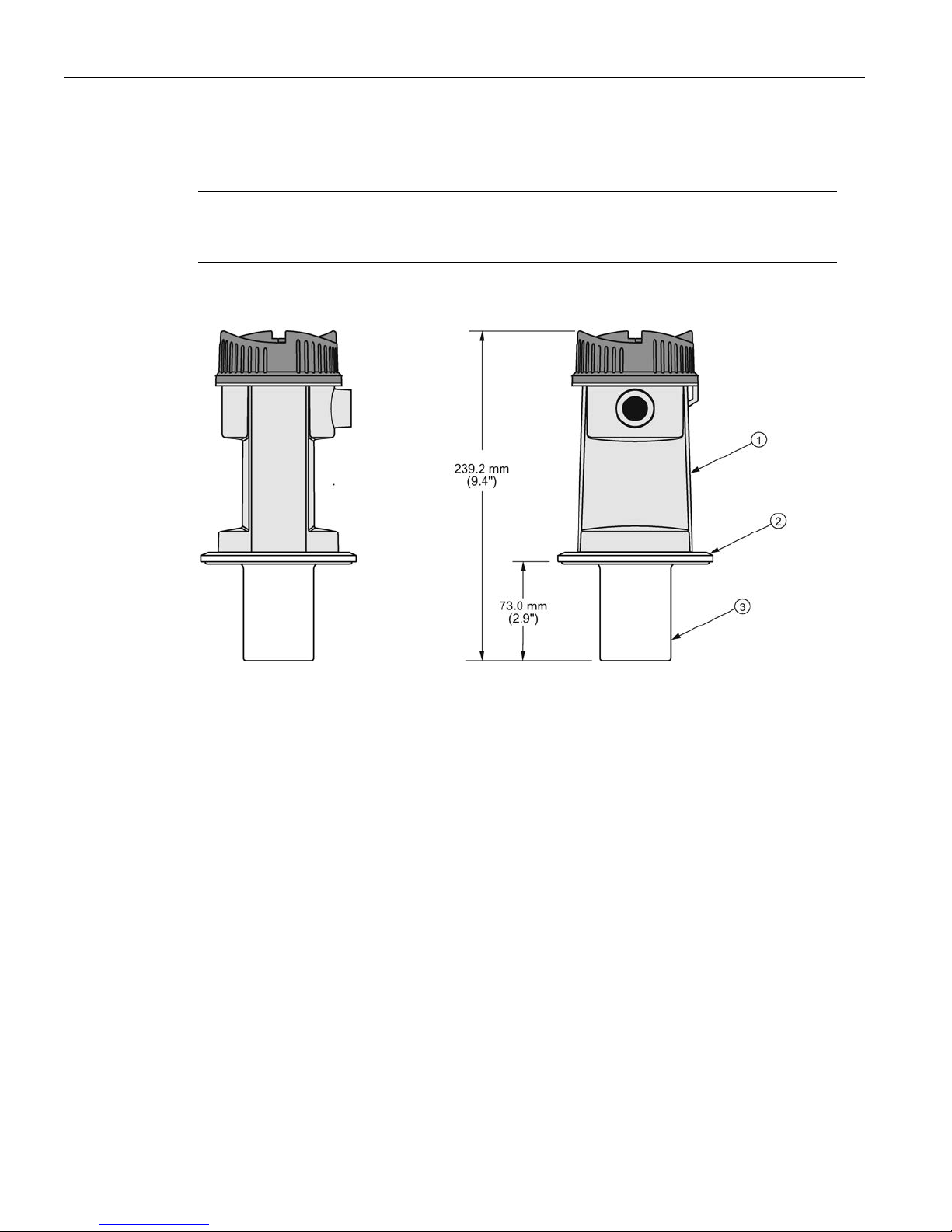
3.4
Flange adapter (optional)
The SITRANS LU180 can be fitted with the optional 75 mm (3" ) flange adapter for mating to 3"
ANSI, DIN 65PN10 and JIS 10K3B flanges.
①
SITRANS LU180
②
Optional flange adapter (2" NPT - 7ML1830-1BT, 2" BSPT - 7ML1830-1BU)
Installing and mounting
3.5 4" Sanitary
SITRANS LU180
12 Operating Instructions, 06/2016, A5E37100674-AA
3.5
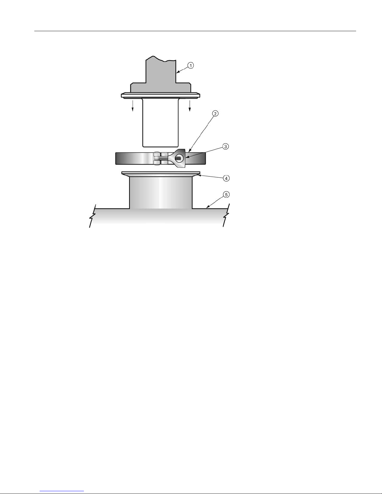
4" Sanitary
Note
•
The sanitary version is suitable for chemical clean-in-place applications to 60 °C (140 °F)
only. Ensure your cleaning chemicals are compatibl e with PVDF.
①
Electronics
②
Mounting flange
③
Sensor
Mounting the sanitary version
1. Mount the SITRANS LU180 onto the top of the tank’s sanita ry ferrul e.
2. Secure mating by surrounding the joint with the clamp.
3. Tighten adjusting wing nut.
Installing and mounting
3.5 4" Sanitary
SITRANS LU180
Operating Instructions, 06/2016, A5E37100674-AA
13
①
SITRANS LU180
④
Ferrule
②
Clamp
⑤
Tank
③
Adjusting wing nut
 Loading...