

Siemens LR200 Quick Start Manual
Quick Start Manual May 2008
sitrans
LR200 (HART)

SITRANS LR200 (HART) with Siemens LUI Interface: Quick Start Manual
This manual outlines the essential features and functions of the SITRANS LR200 (HART). We
strongly advise you to acquire the detailed version of the manual so you can use your device to
its fullest potential. The complete manual can be downloaded from the SITRANS LR200
product page of our web site at: www.siemens.com/LR200
from your local Siemens Milltronics representative.
Questions about the contents of this manual can be directed to:
Siemens Milltronics Process Instruments Inc.
1954 Technology Drive, P.O. Box 4225
Peterborough, Ontario, Canada, K9J 7B1
Email: techpubs.smpi@siemens.com
Copyright Siemens Milltronics
Process Instruments Inc. 2008.
Disclaimer of Liability
All Rights Reserved
We encourage users to purchase authorized bound manuals, or to view electronic versions as designed and
authored by Siemens Milltronics Process Instruments Inc. Siemens Milltronics Process Instruments Inc. will not be
responsible for the contents of partial or
whole reproductions of either bound or
electronic versions.
While we have verified the contents of this manual for agreement with the instrumentation
described, variations remain possible. Thus we
cannot guarantee full agreement. The contents of
this manual are regularly reviewed and corrections are included in subsequent editions. We
welcome all suggestions for improvement.
Technical data subject to change.
. The printed manual is available
English
MILLTRONICS is a registered trademark of Siemens Milltronics Process Instruments Inc.
Technical Support
Support is available 24 hours a day.
To find your local Siemens Automation Office address, phone number, and fax number, go to:
www.siemens.com/automation/partner:
• Click on the tab Contacts by Product then find your product group (+Process Automation
> +Process Instrumentation > +Level Measuring Instruments).
• Select the team Tech nica l Support. Click on Next.
• Click on a continent, then a country, followed by a city. Click on Next.
For on-line technical support go to: www.siemens.com/automation/support-request
• Enter the device name (SITRANS LR200) or order number, then click on Search, and
select the appropriate product type. Click on Next.
• Enter a keyword describing your issue. Then either browse the relevant documentation,
or click on Next to email a description of your issue to Siemens Technical Support staff.
Siemens A&D Technical Support Center: phone +49 180 50 50 222
fax +49 180 50 50 223
7ML19985XC81 SITRANS LR200 (HART) – QUICK START MANUAL Page EN-1
Safety Guidelines
Warning notices must be observed to ensure personal safety as well as that of others, and to
protect the product and the connected equipment. These warning notices are accompanied by
a clarification of the level of caution to be observed.
1)
English
WARNING: relates to a caution symbol on the product, and means that failure to
observe the necessary precautions can result in death, serious injury, and/or
considerable material damage.
WARNING
in death, serious injury, and/or considerable material damage.
1)
: means that failure to observe the necessary precautions can result
Note: means important information about the product or that part of the operating manual.
FCC Conformity
US Installations only: Federal Communications Commission (FCC) rules
WARNING: Changes or modifications not expressly approved by Siemens
Milltronics could void the user’s authority to operate the equipment.
Notes:
• This equipment has been tested and found to comply with the limits for a Class A digital
device, pursuant to Part 15 of the FCC Rules. These limits are designed to provide
reasonable protection against harmful interference when the equipment is operated in a
commercial environment.
• This equipment generates, uses, and can radiate radio frequency energy and, if not
installed and used in accordance with the instruction manual, may cause harmful
interference to radio communications. Operation of this equipment in a residential area is
likely to cause harmful interference to radio communications, in which case the user will
be required to correct the interference at his own expense.
SITRANS LR200
WARNING: SITRANS LR200 is to be used only in the manner outlined in this manual,
otherwise protection provided by the equipment may be impaired.
Note:
• This product is intended for use in industrial areas. Operation of this equipment in a
residential area may cause interference to several frequency based communications.
SITRANS LR200 is a 2-wire 6 GHz pulse radar level transmitter for continuous monitoring of
liquids and slurries in storage and process vessels including high temperature and pressure, to
a range of 20 m (66ft).
The device consists of an electronic circuit coupled to the antenna and either a threaded or
flange type process connection.
1)
This symbol is used when there is no corresponding caution symbol on the product.
Page EN-2 SITRANS LR200 (HART) – QUICK START MANUAL 7ML19985XC81
Communication is via HART1). Signals are processed using Process Intelligence.
Specifications
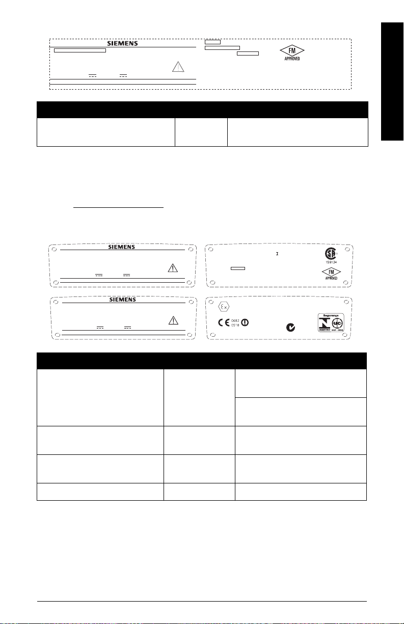
For a complete listing, see the SITRANS LR200 (HART) Instruction Manual. For Approvals
information, please refer to the device nameplate and the process device tag.
Ambient/Operating Temperature
Notes:
• Process temperature and pressure capabilities are dependent upon information on the
process device tag. The reference drawing listed on the tag can be downloaded from the
Siemens website at: www.siemens.com/LR200
• Maximum temperature is dependent on the process connection, antenna materials, and
vessel pressure. See
Maximum Process Temperature Chart
Process Pressure Temperature derating curves are available in the full manual.
ambient temperature (surrounding enclosure)
–40 °C to +80 °C (–40 °F to +176 °F)
process temperature
PP rod:
–40 °C to +80 °C (–40 °F to +176 °F)
PTFE rod or SS horn:
–40 °C to +200 °C (–40 °F to +392 °F)
Power
.
on page 22, for more details.
device
nameplate
process device
tag
English
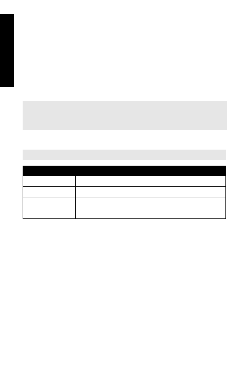
General Purpose:
Non-incendive (FM/US only):
Intrinsically Safe:
Flameproof:
Increased Safety:
Explosion-proof (FM/CSA US/Canada only):
Approvals
•General CSA
• Radio Europe (R&TTE), FCC, Industry Canada
1)
HART® is a registered trademark of HART Communication Foundation.
US/C
, FM, CE
Nominal 24 V DC at
max. 550 Ohm loop
resistance.
Nominal 24 V DC at
max. 250 Ohm loop
resistance.
(continued on next page)
7ML19985XC81 SITRANS LR200 (HART) – QUICK START MANUAL Page EN-3

• Hazardous Flameproof (Europe)
Increased Safety (Europe)
Explosion proof (US/Canada)
1)
2)
3)
English
Note: Use appropriate conduit seals to maintain IP or NEMA rating.
Approvals (continued)
• Hazardous
Non-incendive (US)
Intrinsically Safe
(Europe) ATEX II 1 G, EEx ia IIC T4
(US/Canada) FM/CSA: (barrier required)
Class I, Div. 1, Groups A, B, C, D
Class II, Div. 1, Groups E, F, G
Class III T4
(Australia) ANZEX Ex ia IIC T4
(Tamb = –40 to +80 °C) IP67
(International) IECEX TSA 04.0020X T4
• Marine Lloyd’s Register of Shipping
ABS Type Approval
4)
FM: (barrier not required)
Class I, Div. 2, Groups A, B, C, D T5
5)
ATEX II 1/2 G, EEx dm ia IIC T4
ATEX II 1/2 G, EEx em ia IIC T4
FM/CSA: (barrier not required)
Class I, Div. 1, Groups A, B, C, D
Class II, Div. 1, Groups E, F, G
Class III T4
Programmer (infrared keypad)
Siemens Milltronics Infrared IS (Intrinsically Safe) Hand Programmer for hazardous and all
other locations (battery is non-replaceable with a life expectancy of 10 years in normal use).
• approval ATEX II 1 G, EEx ia IIC T4, certificate SIRA 01ATEX2147
• FM/CSA: Class I, Div. 1, Groups A, B, C, D
• ambient temperature −20 to 40 °C (−5 to 104 °F)
• interface proprietary infrared pulse signal
• power 3 V lithium battery
• weight 150 g (0.3 lb)
• color black
• Part Number 7ML1930-1BK
1)
See
Flameproof wiring
2)
See
Increased safety wiring
3)
See
Explosion-proof wiring (FM/CSA US/Canada only)
4)
See
Non-incendive wiring (FM/US only)
5)
See
Intrinsically Safe wiring
Page EN-4 SITRANS LR200 (HART) – QUICK START MANUAL 7ML19985XC81
on page 9.
on page 10.
on page 10.
on page 11.
on page 11.

Pressure Application
WARNINGS:
• This product is designated as a Pressure Accessory per Directive 97 / 23 / EC, and
is not
intended for use as a safety device.
• Never attempt to loosen, remove, or disassemble process connection or
instrument housing while vessel contents are under pressure.
• Improper installation may result in loss of process pressure.
Installation
WARNINGS:
• Installation shall only be performed by qualified personnel and in
accordance with local governing regulations.
• Materials of construction are chosen based on their chemical compatibility (or
inertness) for general purposes. For exposure to specific environments, check
with chemical compatibility charts before installing.
Notes:
• The Process Device Tag shall remain with the process pressure boundary assembly1). In
the event the device package is replaced, the Process Device Tag shall be transferred to
the replacement unit.
• SITRANS LR200 units are hydrostatically tested, meeting or exceeding the requirements
of the ASME Boiler and Pressure Vessel Code and the European Pressure Equipment
Directive.
1)
English
Installation guidelines
• Provide easy access for viewing the display and programming via the hand programmer.
• Provide an environment suitable to the housing rating and materials of construction.
• Provide a sunshield if the device will be mounted in direct sunlight.
1)
The process pressure boundary assembly comprises the components that act as a barrier against
pressure loss from the process vessel: that is, the combination of process connection body and
emitter, but normally excluding the electrical enclosure.
7ML19985XC81 SITRANS LR200 (HART) – QUICK START MANUAL Page EN-5
Nozzle design
Notes:
• For nozzles 100 mm (4") in length or shorter use the 100 mm (4") shield.
• For nozzles 250 mm (10") in length or shorter use the 250 mm (10") shield.
• For details on other applications, please see the full manual.
English
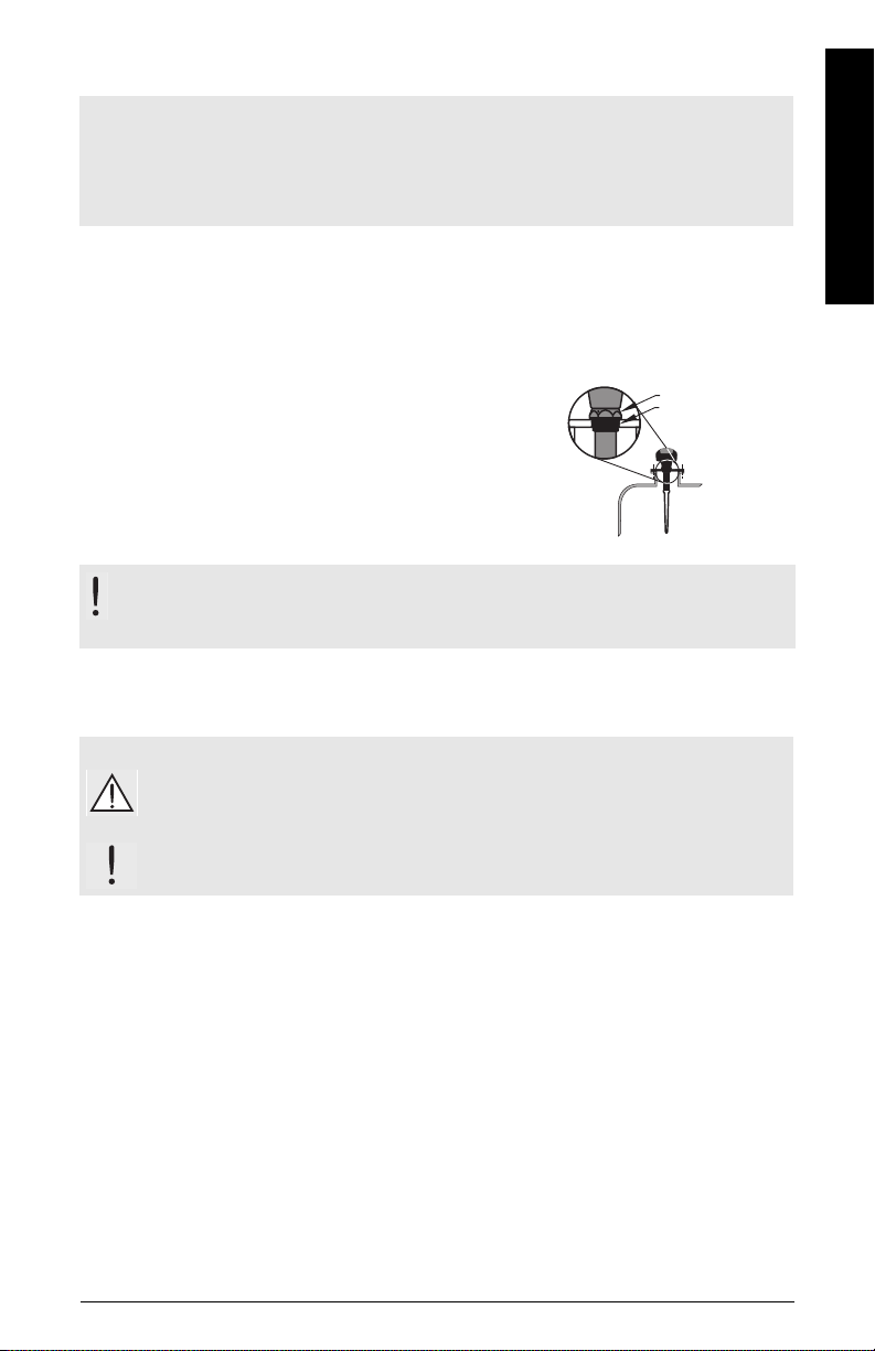
• The end of the shield section should protrude a minimum
of 10 mm (0.4”) to avoid false echoes being reflected from
the nozzle.
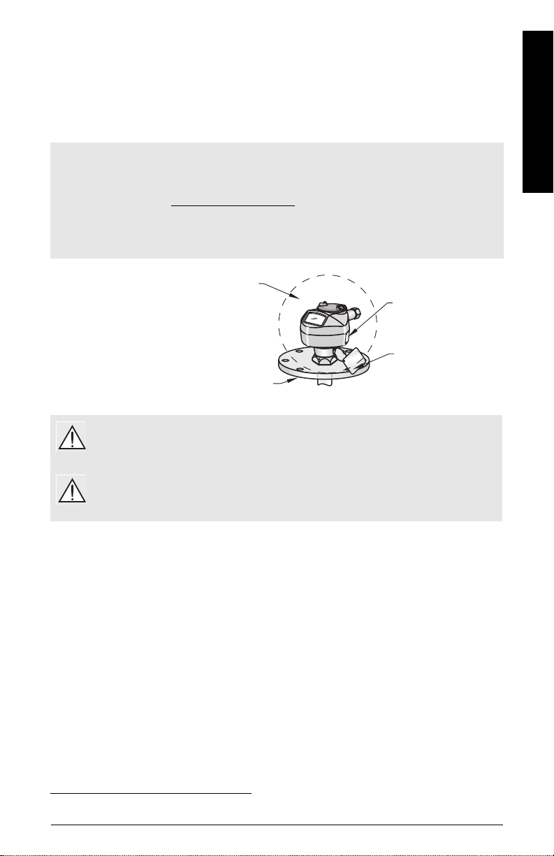
Location on a manhole cover
• A manhole cover is typically a covered nozzle with a
diameter 610 mm (24”) or greater.
• For optimum signal conditions, locate the antenna
off-center, typically 100 mm (4") from the side.
Nozzle location
WARNING: For vessels with conical or parabolic tops, avoid mounting the
instrument at the centre. (The concavity of the top can focus echoes into the centre,
giving false readings.)
shield
10 mm
(0.4")
100 mm (4")
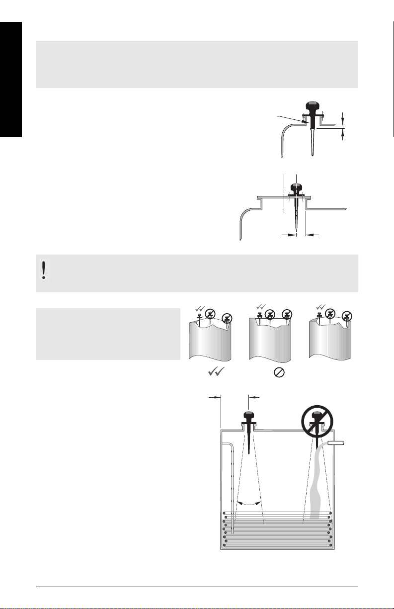
Note: Under certain circumstances, it
may be acceptable to mount the device
at the centre of a flat-topped tank.
Please discuss this with your local
Siemens representative.
• Keep emission cone free of interference
from ladders, pipes, I-beams or filling
streams.
• Locate the antenna away from the side
wall, to avoid interference from indirect
echoes.
• Make allowance for the emission cone
spreading, to avoid interference with
vessel walls or obstructions.
Coni
Conical
preferred
beam
angle
20
Fl at
Flat
undesirable
min. 300 mm (1ft)
per 3 m (10’) of vessel
height
emission
cone
o
Parabolic
Page EN-6 SITRANS LR200 (HART) – QUICK START MANUAL 7ML19985XC81
Installation instructions
Notes:
• There is no limit to the number of times the device can be rotated.
• Orient the front or back of the device towards the closest vessel wall.
• Do not rotate the enclosure after programming and device configuration (a polarity shift
of the transmit pulse may cause an error).
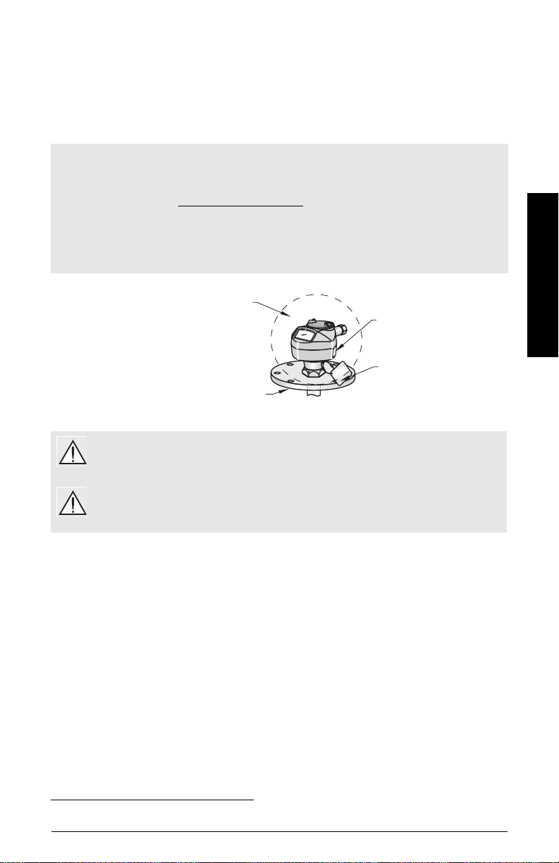
Threaded Version
1) Before inserting the device into its mounting connection, check to ensure the threads are
matching to avoid damaging them.
2) Screw the device into the process connection, and hand
tighten. For pressure applications, use PTFE tape or
other appropriate thread sealing compound, and tighten
the process connection beyond hand-tight (max. torque
40 N·m (30 ft.lbs).
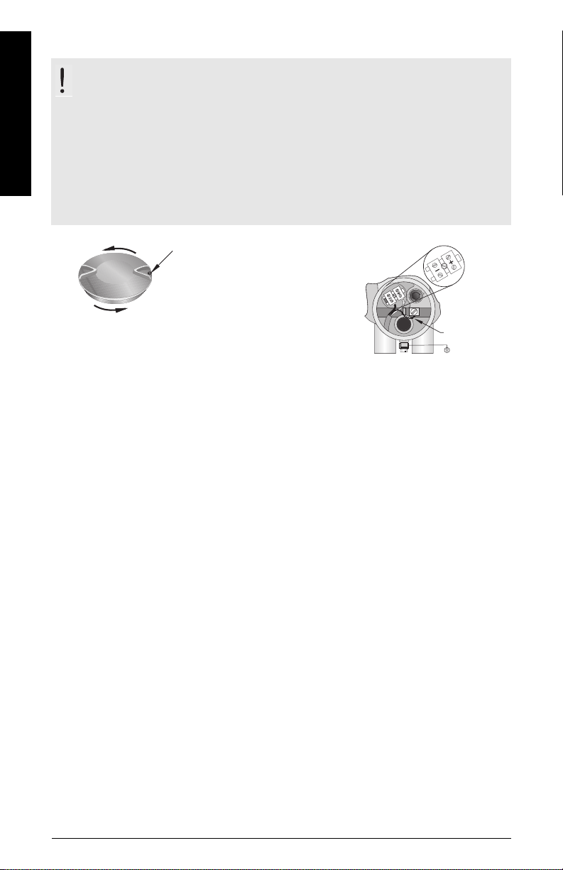
3) To rotate the enclosure, first loosen the three set-screws
securing the locking ring. After positioning the
enclosure, retighten the screws.
locking ring
secured by three
2 mm Allen setscrews
threaded
connection
Flanged Version
WARNING: The user is responsible for the selection of bolting and gasket materials
which will fall within the limits of the flange and its intended use, and which are
suitable for the service conditions.
Wiring
Power
English
WARNINGS:
The DC input terminals shall be supplied from a source providing electrical
isolation between the input and output, in order to meet the applicable safety
requirements of IEC 61010-1.
All field wiring must have insulation suitable for rated voltages.
7ML19985XC81 SITRANS LR200 (HART) – QUICK START MANUAL Page EN-7
Connecting SITRANS LR200
WARNINGS:
• Check the device nameplate and process device tag, to verify the approval rating.
• Use appropriate conduit seals to maintain IP or NEMA rating.
English
• Read
Notes:
• For detailed wiring instructions, please refer to the full Instruction Manual.
• Use twisted pair cable: AWG 22 to 14 (0.34 mm
• Separate cables and conduits
1) Use a 2 mm Allen key to loosen the lid-lock set screw
2) Strip the cable jacket for approximately 70 mm (2.75") from the end of the cable, and
3) Connect the wires to the terminal as shown: the polarity is identified on the terminal
4) Ground the device according to local regulations.
5) Tighten the gland to form a good seal.
6) Close the lid and secure the locking ring before programming and device configuration.
Instructions specific to hazardous area installations
2
may be required to conform to standard instrumentation
to 2.5 mm2).
on page 13.
wiring practices, or electrical codes.
2 mm lid-lock set screw.
then unscrew the cover.
thread the wires through the gland.
block.
Do not rotate the device after it has been configured, as this may cause an error.
cable shield
(if used)
Page EN-8 SITRANS LR200 (HART) – QUICK START MANUAL 7ML19985XC81
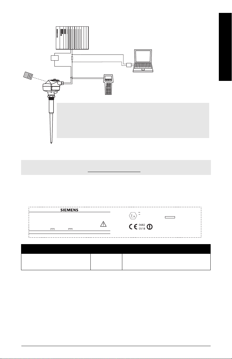
Connecting HART: typical PLC/mA configuration
active PLC
power
supply
SITRANS
LR200
R = 250 Ω
HART
modem
HART
communicator
Notes:
• Depending on the system design, the power supply may be separate
from the PLC, or integral to it.
• Loop resistance (total of cable resistance plus 250 Ohm [resistor]) must
be less than 550 Ohm for the device to function properly.
Wiring setups for hazardous area installations
Note: ATEX certificates and connection drawings listed below can be downloaded from the
product page of our website at: www.siemens.com/LR200.
There are five wiring options for hazardous area installations. In all cases, check the device
nameplate and process device tag to verify the approval rating.
1. Flameproof wiring
English
SITRANSLR 200
7ML1234-56789-0ABC-D
SerialNo: GYZ/S1034567
Encl.:NEMA /TYPE 4X,6, IP67,IP68
Amb.Temp.:–40°Cto80 °C
PowerRating: 24V
Nom.,30 V
SiemensMilltronics ProcessInstruments Inc.,Peterborough
Madein Canada
Max.,4 -20mA
SIRA
II 1/2G
EEx dmia IIC T4
05ATEX1001X
HART
Um= 250V
Approval Rating Valid for: Reference
ATEX II 1/2 G, EEx dm ia IIC T4 Europe
• For power demands see
Curve 2 (Flameproof, Increased Safety, Explosion-proof)
page 23.
• For wiring requirements follow local regulations.
•See also
Instructions specific to hazardous area installations
certificate listed above.
7ML19985XC81 SITRANS LR200 (HART) – QUICK START MANUAL Page EN-9
Flameproof/Increased Safety: ATEX Cer-
on page A-1.
tificate
on
on page 13 and the ATEX
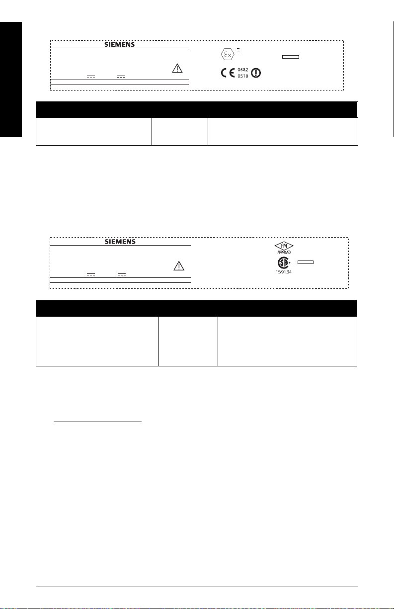
2. Increased safety wiring
SITRANSLR 200
7ML1234-56789-0ABC-D
English
SerialNo: GYZ/S1034567
Encl.:NEMA /TYPE 4X,6, IP67,IP68
Amb.Temp.:–40°Cto80 °C
PowerRating: 24V
Nom.,30 V
SiemensMilltronics ProcessInstruments Inc.,Peterborough
Madein Canada
Max.,4 -20mA
SIRA
Approval Rating Valid for: Reference
ATEX II 1/2 G, EEx em ia IIC T4 Europe
• For power demands see
Curve 2 (Flameproof, Increased Safety, Explosion-proof)
page 23.
• For wiring requirements follow local regulations.
•See also
Instructions specific to hazardous area installations
certificate listed above.
Flameproof/Increased Safety: ATEX Certificate
3. Explosion-proof wiring (FM/CSA US/Canada only)
SITRANSLR 200
7ML1234-56789-0ABC-D
SerialNo: GYZ/S1034567
Encl.:NEMA /TYPE 4X,6, IP67,IP68
Amb.Temp.:–40°Cto80 °C
PowerRating: 24V
Nom.,30 V
SiemensMilltronics ProcessInstruments Inc.,Peterborough
Max.,4 -20mA
Madein Canada
Approval Rating Valid for: Reference
FM/CSA:
Class I, Div. 1, Groups A, B, C, D
Class II, Div. 1, Groups E, F, G
Class III T4
US/Canada
ClassI ;Div1; Group A,B, C,D
ClassII ;Div1; GroupE,F,G
ClassIII
Temp.Code:T4
P
erdrawing: 23650597
WARNING: Do Not Remove Cover While Circuits Are Live
FM/CSA Explosion Proof Connection
Drawing number 23650597
II 1/2 G
EEx emia IIC T4
05ATEX1001X
HART
Um= 250V
on page A-1.
on page 13 and the ATEX
FCCID: NJA-LR200
CANADA:267P-LR 200
HART
on
• For power demands see
Curve 2 (Flameproof, Increased Safety, Explosion-proof)
on
page 23.
• For wiring requirements (North America only) see the connection drawing listed above,
which can be downloaded from the product page of our website at:
www.siemens.com/LR200
.
Page EN-10 SITRANS LR200 (HART) – QUICK START MANUAL 7ML19985XC81
4. Non-incendive wiring (FM/US only)
7ML1234-56789-0ABC-D
SerialNo: GYZ/S1034567
Encl.:NEMA /TYPE 4X,6, IP67
Amb.Temp.:–40°Cto80 °C
PowerRating: 24V
Nom.,30V
SiemensMilltronics ProcessInstruments Inc.,Peterborough
Madein Canada
Max.,4-20mA
CANADA:267PFCCID:NJA-LR200
This device complies with Part 15 of the FCC Rules.
Operation is subject to the following two conditions
1)This device may not cause harmful interference and
2)This device must accept any interference received,
including interference that may cause undesired operation
Class I, Div.2,
Group A,B,C,D
Temp.Code:T5
Approval Rating Valid for: Reference
FM:
Class I, Div. 2, Groups A, B, C, D T5
• For power demands, see
incendive)
on page 23.
US
Curve 1 (General Purpose, Intrinsically Safe, Non-
• For wiring requirements (North America only) see the connection drawing listed
above, which can be downloaded from the product page of our website at:
www.siemens.com/LR200
.
FM Non-Incendive Connection Drawing number 23650537
5. Intrinsically Safe wiring
SITRANS LR200
7ML1234-56789-0ABC-D
Serial No: GYZ / S1034567
Encl.: NEMA / TYPE 4X, 6, IP67, IP68
Amb.Temp.:– 40 °C to 80 °C
Power Rating: 24V
SITRANS LR200
7ML1234-56789-0ABC-D
Serial No: GYZ / S1034567
Encl.: NEMA / TYPE 4X, 6, IP67, IP68
Amb.Temp.:– 40 °C to 80 °C
Power Rating: 24V
Nom.,30 V
Siemens Milltronics Process Instruments Inc., Peterborough
Siemens Milltronics Process Instruments Inc., Peterborough
Made in Canada
Nom.,30 V
Made in Canada
Max.,4 -20mA
Max.,4 -20mA
Class I, Div 1, Group A, B, C, D
Class II, Div 1, Group E, F,G
Class III
Temp.Code: T4
HART
CSA per drawingA5E01003039
FM per drawing A5E01003040
WARNING: Possible Static Hazard, Do Not Rub Or Clean On Site
1GII
EEx ia IIC T4
SIRA 06ATEX2378X
HART 5.8 GHz
WARNING: PossibleStatic Hazard, Do Not Rub OrClean On Site.
Ui=30V
Ii = 120 mA
Pi = 0.8 W
Ci=15nF
Li = 0.1 mH
Vmax=30V
max = 120 mA
Pmax = 0.8 W
Ci=15nF
Li = 0.1 mH
IC: 267P-LR200
FCC ID: NJA-LR200
IECEx TSA 04.0020X
ANZEx 04.3016X
Ex ia IIC T4
N117
English
R
Approval Rating Valid for: Reference
FM/CSA:
Class I, Div. 1, Groups A, B, C, D
Class II, Div. 1, Groups E, F, G
US/Canada
Class III
ATEX II 1 G, EEx ia IIC T4 Europe
ANZEX Ex ia IIC T4
(Tamb = –40 to 80 °C) IP67
Australia
IECEX TSA 04.0020X International
• For power demands see
Curve 1 (General Purpose, Intrinsically Safe, Non-incendive)
page 23.
7ML19985XC81 SITRANS LR200 (HART) – QUICK START MANUAL Page EN-11
FM Intrinsically Safe Connection
Drawing number A5E01003040
CSA Intrinsically Safe Connection
Drawing number A5E01003039
Intrinsically Safe: ATEX Certificate
on page A-5
on
• For wiring requirements:
N. America: See the connection drawings listed above, which can be
downloaded from the product page of our website at:
www.siemens.com/LR200
Europe: Follow local regulations.
Australia: Follow local regulations.
English
International: Follow local regulations.
• Use appropriate conduit seals to maintain IP or NEMA rating.
• Recommended intrinsically safe barriers are listed under
on page 12.
• Refer to
Instructions specific to hazardous area installations
certificate listed above.
.
Passive Shunt Diode Barriers
on page 13 and the ATEX
Note: Selecting a suitable PLC input module, power supply, or barrier requires knowledge
about Intrinsic Safety and the application. It is the responsibility of the installer to ensure that
the intrinsically safe installation complies with both the apparatus approval requirements and
the relevant national code of practice.
Passive Shunt Diode Barriers
Note: A well regulated supply voltage is required.
Manufacturer Part Number
MTL 787SP+ (Dual Channel)
MTL 7787P+ (Dual Channel)
Stahl 9001/01-280-100-10 (Single Channel)
Stahl 9002/01-280-110-10 (Dual Channel)
How to select a passive barrier for SITRANS LR200
To make sure that the barrier safety description is suitable for the LR200 Intrinsically Safe (IS)
input parameters, carry out the following calculations:
Re-e = max. end-to-end resistance of the barrier
Rloop = loop resistance (total of cable resistance plus e.g. sense resistance,
displays, and/or PLC inputs)
Vbarrier = value of any non-linear voltage drops due to the barrier
1) Determine the value for Re-e from the data sheet.
2) Calculate the total value for Rloop: by adding, for example, sense resistance, displays,
and/or PLC inputs.
3) Calculate Rworking = Re-e + Rloop.
Page EN-12 SITRANS LR200 (HART) – QUICK START MANUAL 7ML19985XC81
4) Determine the value of Vbarrier from the barrier data sheet (for example, voltage drops
due to diodes).
5) Calculate Vworking = Vsupply – Vbarrier.
Use the values for Vworking and Rworking to confirm that operation is within the shaded area
of the graph
Curve 1 (General Purpose, Intrinsically Safe, Non-incendive)
on page 23.
Notes:
• The following list is not exhaustive: there are many IS power supplies and barriers on the
market, which will work with the LR200.
• The PLC input modules and barriers listed below have all been tested and are functionally
compatible with the LR200.
Active barriers (repeating barriers)
Manufacturer Part Number
MTL 706
MTL 7206
Stahl 9001/51-280-110-14
Pepperl+Fuchs KSD2-CI-S-Ex
Pepperl+Fuchs KFD2-STC3-Ex1
MTL E02009 - verify
MTL E02010
Instructions specific to hazardous area installations
(Reference European ATEX Directive 94/9/EC, Annex II, 1/0/6)
The following instructions apply to equipment covered by certificate numbers
SIRA 06ATEX2378X, SIRA 05ATEX1001X:
1) For use and assembly, refer to the main instructions.
2) The equipment is certified for use as Category 1G equipment.
3) The equipment may be used with flammable gases and vapors with apparatus group IIC,
IIB, and IIA, and temperature classes T1, T2, T3, and T4.
4) The equipment is certified for use in an ambient temperature range of –40 °C to +80 °C.
5) The equipment has not been assessed as a safety related device (as referred to by
Directive 94/9/EC Annex II, clause 1.5).
6) Installation and inspection of this equipment shall be carried out by suitably trained
personnel in accordance with the applicable code of practice (EN 60079-14 and EN 6007917 in Europe).
English
7ML19985XC81 SITRANS LR200 (HART) – QUICK START MANUAL Page EN-13
7) The equipment is non-repairable.
8) The certificate numbers have an ‘X’ suffix, which indicates that special conditions for safe
use apply. Those installing or inspecting this equipment must have access to the
certificates.
9) If the equipment is likely to come into contact with aggressive substances, then it is the
English
responsibility of the user to take suitable precautions that prevent it from being adversely
affected, thus ensuring that the type of protection is not compromised.
Aggressive substances: e.g. acidic liquids or gases that may attack metals, or
solvents that may affect polymeric materials.
Suitable precautions: e.g. establishing from the material’s data sheet that it
is resistant to specific chemicals.
Activating SITRANS LR200
Power up the device. SITRANS LR200 automatically starts up in Measurement mode. (To
change the language displayed see
language)
on page 17.)
Selecting a listed option (for example, selecting a
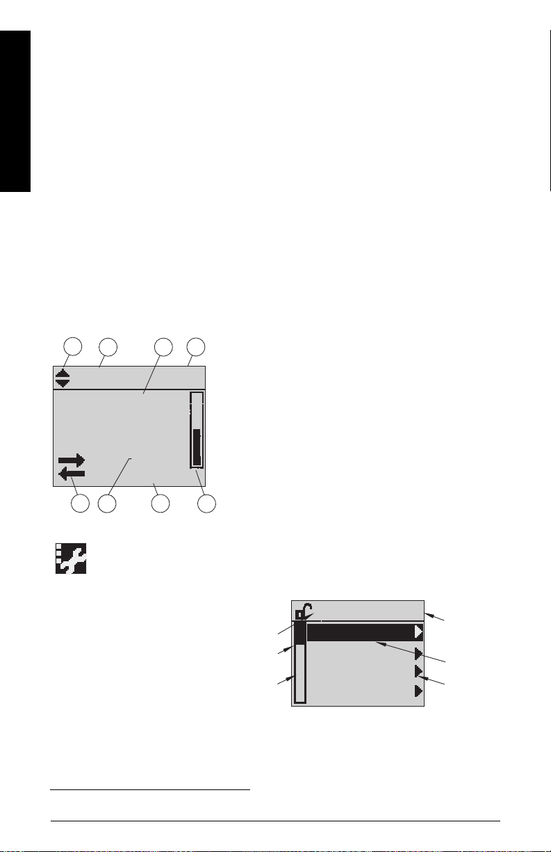
The LCD Display
Measurement mode
1342
LEVEL
1)
((((normal operation)
[]
M
18.91
21.40 °C
DATA EXCH.
678
Fault present
S: 0 LOE
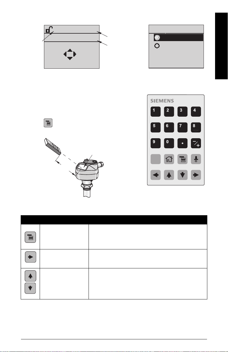
PROGRAM mode
Navigation view
• A visible menu bar indicates
the menu list is too long to
display all items.
• A deeper item band represents
a shorter menu list.
7 – text area displays a fault code and an error message
8 – service required icon appears
1 – toggle indicator for linear units or %
2 – selected operation: level, space, or distance
3 – measured value (level or volume, space, or distance)
4 – units
5 – bar graph indicates level
1)
6 – secondary region indicates on request
temperature, echo confidence, loop current, or distance
7 – text area displays status messages
8 – device status indicator
5
current
menu
item
band
menu
bar
LEVEL METER
QUICK START
SETUP
DIAGNOSTICS
SERVICE
electronics
1
current
item
number
current
item
pointer
1)
In response to a key press request: see
Page EN-14 SITRANS LR200 (HART) – QUICK START MANUAL 7ML19985XC81
Key functions in Measurement mode
on page 15.
Parameter view Edit view
parameter
number
parameter
value/
selection
parameter
name
MATERIAL
PREVIOUS
NEXT
1.1
LIQUID
EDITBACK
Handheld Programmer
(Part No. 7ML1930-1BK)
The programmer is ordered separately.
• Point the programmer at the display (from a maximum
distance of 300 mm [1 ft.]).
• Press Mode to toggle between Measurement
and PROGRAM mode.
handheld programmer
display
Max. 300 mm
(1 ft)
MATERIAL
LIQUID
LIQUID LOW DK
C
1.1
English
Key functions in Measurement mode
Key Function Result
Opens the menu level last displayed in this power cycle, or
Mode opens PROGRAM mode.
RIGHT arrow
opens PROGRAM
mode.
UP or DOWN arrow
toggles between linear
units and percent.
7ML19985XC81 SITRANS LR200 (HART) – QUICK START MANUAL Page EN-15
menu level 1 if power has been cycled since exiting PRO-
GRAM mode or more than 10 minutes have elapsed since
PROGRAM mode was used.
Opens menu level 1.
LCD displays measured value in either linear units or per-
cent.
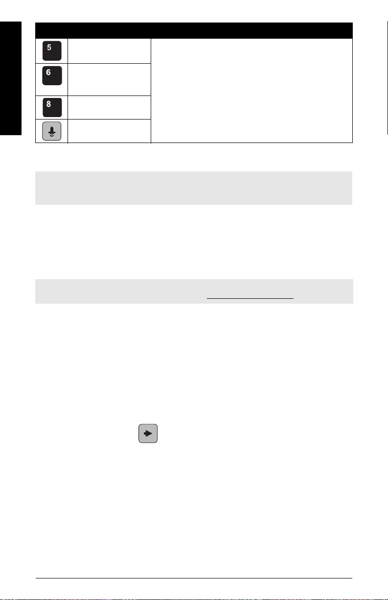
Key Function Result
Updates the loop current.
Updates internal
enclosure tempera-
English
ture reading.
Updates echo confi-
dence value.
Updates distance mea-
surement.
New value is displayed in LCD secondary region.
Programming SITRANS LR200
Note: SITRANS LR200 automatically returns to Measurement mode after a period of
inactivity in PROGRAM mode (between 15 seconds and 10 minutes, depending on the menu
level).
Settings can be modified locally via the Local User Interface or remotely via SIMATIC PDM.
The Local User Interface (LUI) consists of an LCD display and a handheld programmer.
•See
Quick Start Wizard via the handheld programmer
Quick Start Wizard via SIMATIC PDM
•See
on page 21.
Parameter menus
Note: For the complete list of parameters with instructions, see the full manual. It can be
downloaded from the product page of our website at: www.siemens.com/LR20 0.
on page 18.
Parameters are identified by name and organized into
function groups, then arranged in a 5-level menu
structure.
1. QUICK START
2. SETUP
3. DIAGNOSTICS
3.14. MEAS. VALUES
3.14.1. CURR. INTERN. TEMP.
Accessing parameters via the handheld programmer
1. Enter PROGRAM mode
a) Point the programmer at the display from a maximum distance of 300 mm (1 ft).
b) Press RIGHT arrow to open menu level 1.
Page EN-16 SITRANS LR200 (HART) – QUICK START MANUAL 7ML19985XC81
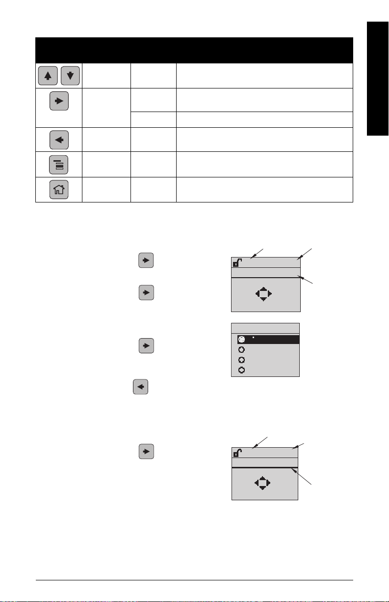
2. Navigating: key functions in Navigation mode
Key Name
UP or DOWN
arrow
RIGHT arrow
LEFT arrow
Mode
Home
Menu
level
menu or
parameter
menu
Function
• Scroll to previous or next menu or parameter.
• Go to first parameter in the selected menu
• or open next menu.
parameter • Open Edit mode.
menu or
parameter
menu or
parameter
menu or
parameter
• Open parent menu.
• Change to MEASUREMENT mode.
• Open menu level 1.
3. Editing in PROGRAM mode
Selecting a listed option (for example, selecting a language)
a) Navigate to Language (7).
b) Press RIGHT arrow to open parameter
view.
c) Press RIGHT arrow again to open Edit
mode. The current selection is highlighted.
parameter name
LANGUAGE
BACK
PREVIOUS
NEXT
ENGLISH
EDIT
7
parameter
number
current
selection
English
d) Scroll to a new selection.
LANGUAGE
7
ENGLISH
Press RIGHT arrow to accept it. The
LCD returns to parameter view and displays
the new selection.
GERMAN
FRENCH
SPANISH
e) Press LEFT arrow to return to the menu.
Changing a numeric value
a) Navigate to the desired parameter.
b) Press RIGHT arrow to open parameter
view. The current value is displayed.
7ML19985XC81 SITRANS LR200 (HART) – QUICK START MANUAL Page EN-17
parameter name
LOW CALIB. 1.5
20.00 M
PREVIOUS
EDITBACK
NEXT
parameter
number
current
value
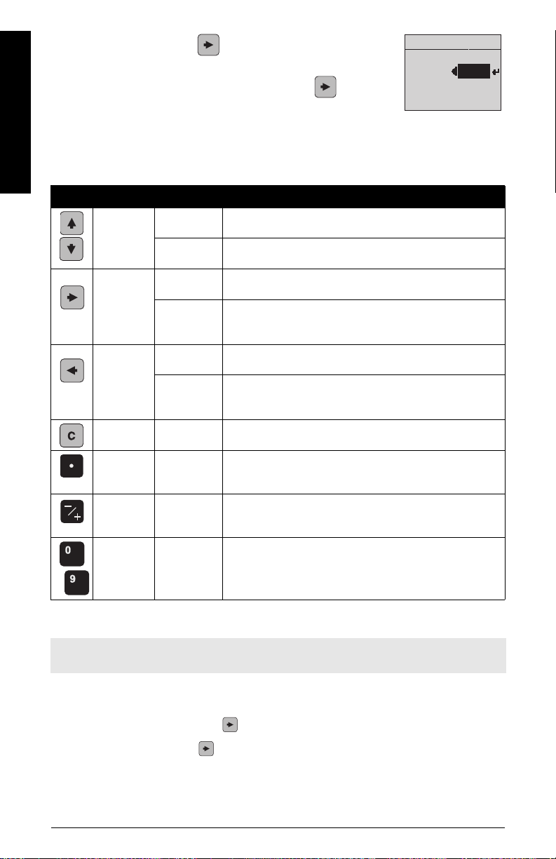
c) Press RIGHT arrow again to open Edit mode. The
current value is highlighted.
d) Key in a new value, and press RIGHT arrow to accept
it.
English
The LCD returns to parameter view and displays the new
selection.
Key functions in Edit mode
Key Name Function
UP or
DOWN
arrow
RIGHT arrow
LEFT arrow
Clear
Selecting
options
Numeric
editing
Selecting
options
Numeric
editing
Selecting
options
Numeric
editing
Numeric
editing
LOW CALIB.
1.5
+20.00
• Scrolls to item.
• Increments or decrements digits
• Toggles plus/minus sign
• Accepts the data (writes the parameter)
• Changes from Edit to Navigation mode
• Moves cursor one space to the right
• or with cursor on Enter sign, accepts the data and changes
from Edit to Navigation mode
•Cancels Edit mode without changing the parameter
•Moves cursor to plus/minus sign if this is the first key
pressed
• or moves cursor one space to the left.
• Erases the display.
M20.00
Decimal
point
Plus/minus
sign
Numeral
to
Numeric
editing
Numeric
editing
Numeric
editing
• Enters a decimal point.
• Changes the sign of the entered value.
• Enters the corresponding character.
Quick Start Wizard via the handheld programmer
Note: Each time the Quick Start Wizard is initiated, the start-up settings are factory defaults.
The Wizard will not recall previous user-defined settings.
1. Quick Start
a) Point the programmer at the display (from a maximum distance of 300 mm [1 ft.]),
then press RIGHT arrow to activate PROGRAM mode and open menu level 1.
b) Press RIGHT arrow twice to navigate to menu item 1.1 and open parameter
view.
Page EN-18 SITRANS LR200 (HART) – QUICK START MANUAL 7ML19985XC81
c) Press RIGHT arrow to open Edit mode or DOWN arrow to accept default
values and move directly to the next item.
d) To change a setting, scroll to the desired item or key in a new value.
e) After modifying a value, press RIGHT arrow to accept it and press DOWN arrow
to move to the next item.
f) Quick Start settings take effect only after you select Ye s to Apply changes in
step 1.7.
1.1. Material
Options
LIQUID
LIQUID LOW DK (low dielectric liquid)
1.2. Response Rate
Sets the reaction speed of the device to measurement changes in the target range.
SLOW 0.1 m/minute
Options
MED 1.0 m/minute
FAST 10.0 m/minute
Use a setting just faster than the maximum filling or emptying rate (whichever is greater).
1.3. Sensor Units
Selects the units for the Quick Start variables (high and
low calibration point, and level, distance, or space).
Options
M, CM, MM, FT, IN
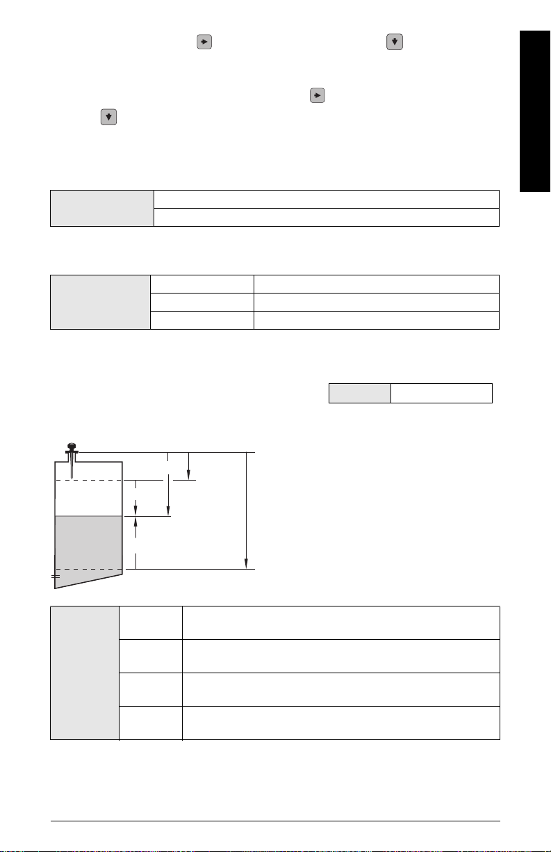
1.4. Operation
sensor
reference
point
space
distance
high cal.
point
English
level
low cal.
point
Operation
types
NO
SERVICE
LEVEL
SPACE
DISTANCE
The SITRANS LR200 stops updating measurements and associated loop current. Last valid measurement is displayed.
Distance to material surface referenced from Low Calibration
Point (process empty level).
Distance to material surface referenced from High Calibration
Point (process full level).
Distance to material surface referenced from Sensor Reference
Poi nt.
7ML19985XC81 SITRANS LR200 (HART) – QUICK START MANUAL Page EN-19
1.5. Low Calibration Point
Distance from Sensor Reference to Low Calibration Point: usually process empty level.
Values
Range: 0.0000 to 20.000 m
1.6. High Calibration Point
Distance from Sensor Reference to High Calibration Point: usually process full level.
English
Values
Range: 0.0000 to 20.000 m
1.7. Apply? (Apply changes)
In order to save the Quick Start settings it is necessary to select Yes to apply changes.
Options
YES, NO
Display shows DONE when Quick Start is successfully completed.
Press Mode to return to Measurement mode. SITRANS LR200 is now ready to operate.
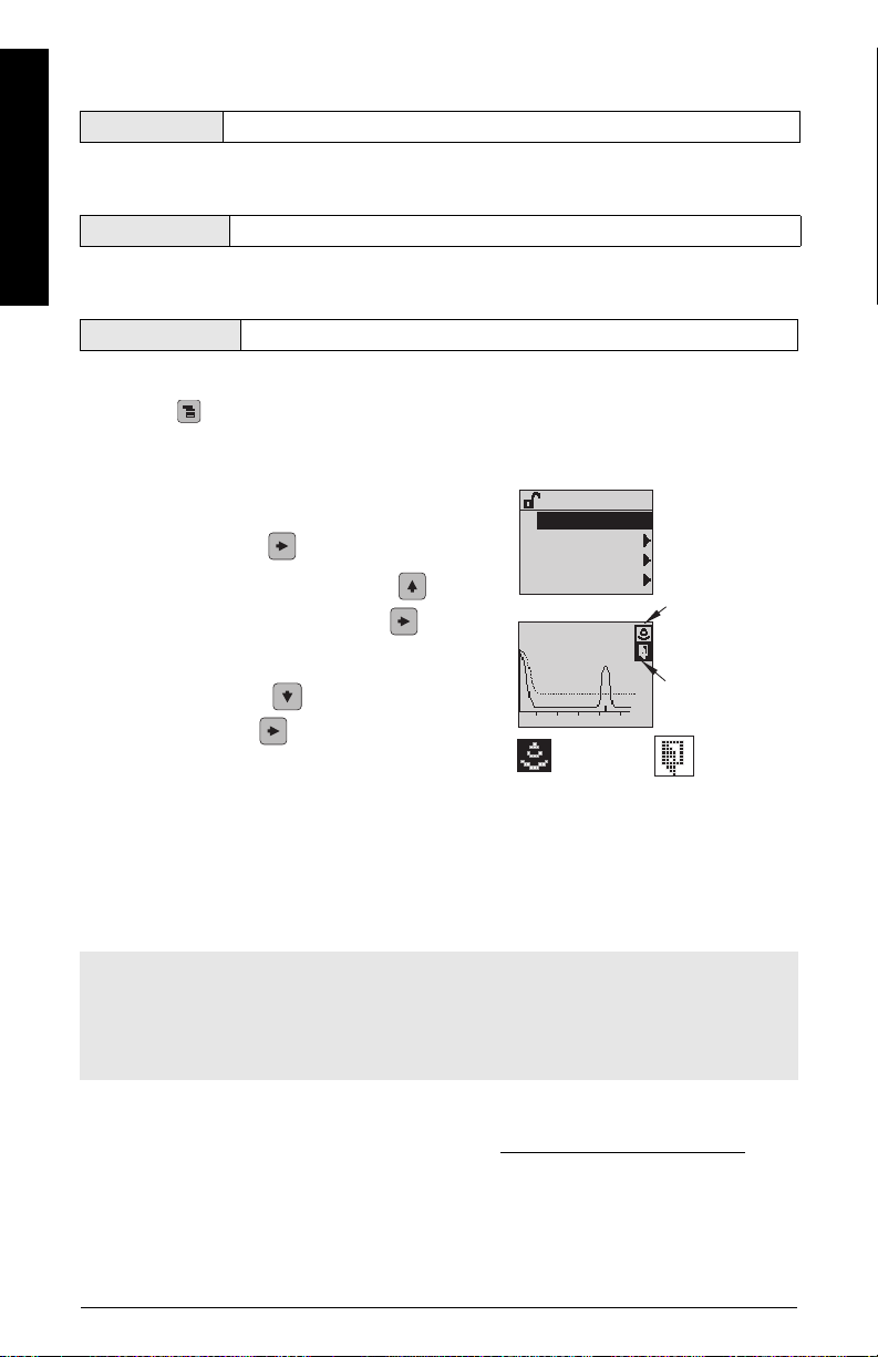
Requesting an Echo Profile
1) In PROGRAM mode, navigate to: Level Meter >
Diagnostics (3) > Echo Profile (3.1).
2) Press RIGHT arrow to request a profile.
3) In the Profile screen, press UP arrow to select
the Transmit icon, and RIGHT arrow to update
the profile.
4) Press DOWN arrow to select the Exit icon,
then RIGHT arrow to return to previous menu.
DIAGNOSTICS
ECHO PROFILE
MEAS. VALUES
REMAIN. DEV. LIFE
RE .MAIN SENS.LIFE
C:38 A:TF D:4.25
12345
transmit icon,
selected
3.1
transmit icon,
deselected
exit icon,
selected
exit icon,
deselected
SITRANS LR200 Communications: HART
• You will need the full manual to acquire the list of applicable parameters.
• We recommend that you use SIMATIC Process Device Manager (PDM) to program your
device.
SIMATIC PDM
Notes:
• SIMATIC PDM Rev. 6.0 SP3 or higher is recommended.
• SIMATIC PDM Rev. 5.2 SP1 is supported only for basic configuration and troubleshooting.
For advanced features such as the Quick Start wizard, Revision 6.0 SP3 or higher is
required.
SIMATIC PDM is a software package used to commission and maintain SITRANS LR200 and
other process devices. Please consult the operating instructions or online help for details on
using SIMATIC PDM. (You can find more information at: www.siemens.com/simatic-pdm
Products and Solutions > Products and Systems > Communications and Software > Process
Device Manager.)
Page EN-20 SITRANS LR200 (HART) – QUICK START MANUAL 7ML19985XC81
. Go to
Electronic Device Description (EDD)
• You can locate the EDD in Device Catalog, under Sensors/Level/Echo/Siemens
Milltronics/SITRANS LR200.
• Check the product page of our website at: www.siemens.com/LR200
to make sure you have the latest version of SIMATIC PDM, the most recent Service Pack
(SP) and the most recent hot fix (HF). If you need to install a new EDD see
new device
below.
, under Downloads,
Configuring a
Configuring a new device
Note: Clicking on Cancel during an upload from device to SIMATIC PDM will result in some
parameters being updated.
1. Check that you have the most recent EDD, and if necessary download it from the product
page listed above. Save the files to your computer, and extract the zipped file to an easily
accessed location. Launch SIMATIC PDM – Manager Device Catalog, browse to the
unzipped EDD file and select it.
2. Launch SIMATIC PDM and create a new project for LR200. Application Guides for setting
up HART devices with SIMATIC PDM can be downloaded from the product page of our
website at: www.siemens.com/LR200
3. Upload parameters to the PC/PG.
4. Configure the device via the Quick Start wizard (see below).
.
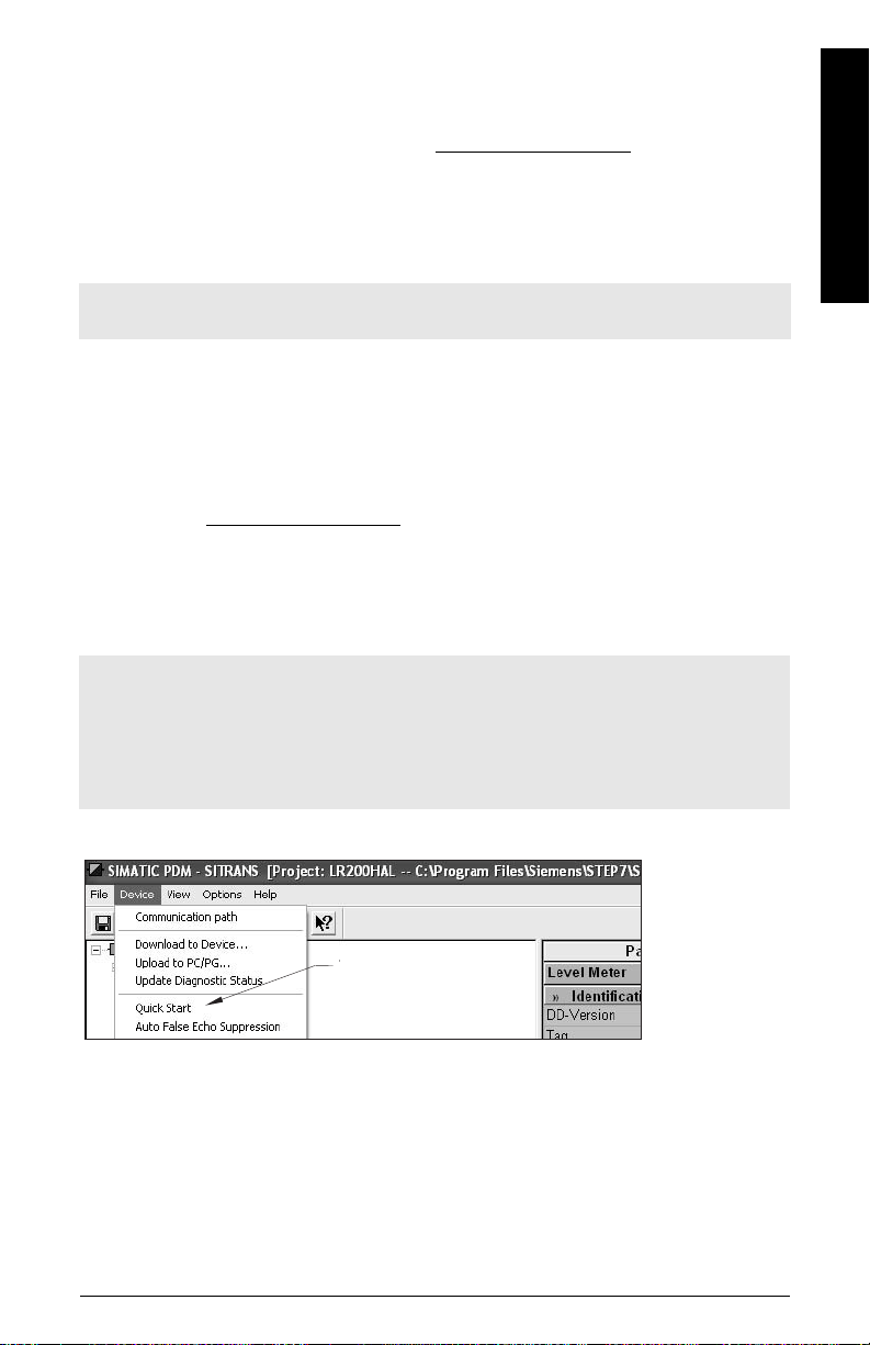
Quick Start Wizard via SIMATIC PDM
Notes:
• The Quick Start wizard settings are inter-related and changes apply only after you click on
Transfer at the end of step 5.
• Each time the Quick Start Wizard is initiated, the start-up settings are factory defaults.
The Wizard will not recall previous user-defined settings.
• Click on BACK to return and revise a setting or Cancel to exit the Quick Start.
English
Launch SIMATIC PDM, open the menu Device – Quick Start, and follow steps 1 to 5.
Quick
Start
7ML19985XC81 SITRANS LR200 (HART) – QUICK START MANUAL Page EN-21
Maintenance
SITRANS LR200 requires no maintenance or cleaning under normal operating conditions. If
cleaning becomes necessary under severe operating conditions:
1. Note the antenna material and the process medium, and select a cleaning solution that
will not react adversely with either.
2. Remove the device from service and wipe the antenna clean using a cloth and suitable
English
cleaning solution.
Unit Repair and Excluded Liability
For detailed information, please see the inside back cover.
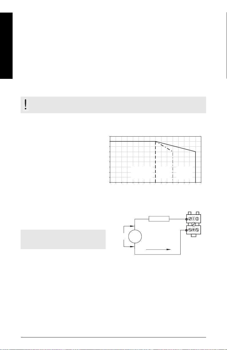
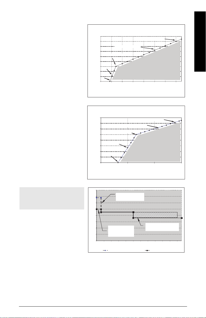
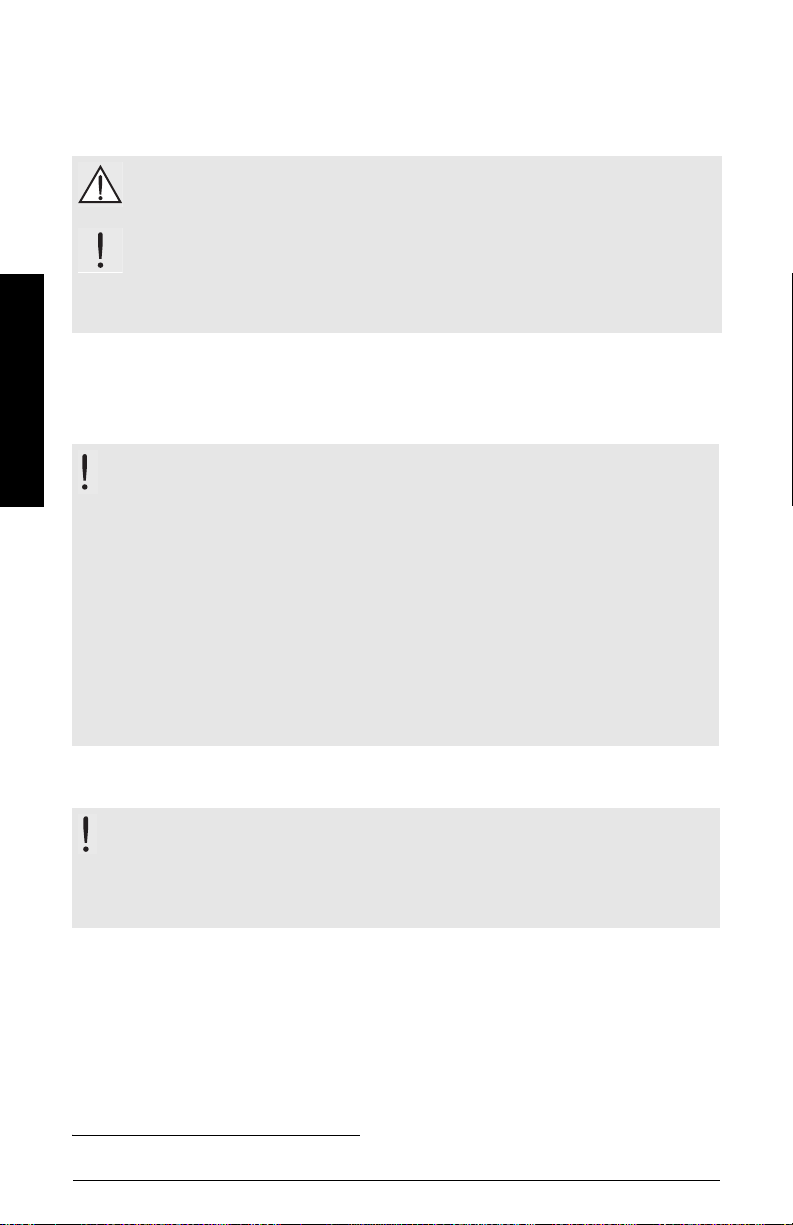
Maximum Process Temperature Chart
WARNING: Internal temperature must not exceed 80 °C (176 °F).
Maximum Flange and Process Temperatures versus allowable ambient
for flange adapter versions of SITRANS LR200
• The chart is for guidance only.
• It does not represent every
possible process connection
arrangement. For example, it will
NOT apply if SITRANS LR200 is
mounted directly on a metallic
vessel surface.
• It does not take into consideration
heating from direct sunshine
exposure.
• You can use parameter 3.14.1 to
monitor the current internal temperature.
90
80
C)
o
70
60
50
40
30
20
10
Ambient Temperature (
0
0 10 20 30 40 50 60 70 80 90 100 110 120 130 140 150 160
Process Flange Surface Temperature (oC)
PP rod
temperature
(no flange)
flange
tempera-
ture
process
tempera-
ture
Loop power
Typical connection drawing
Note: Loop voltage is the voltage at the
terminals of the power supply (not the
voltage at the terminals of the device).
Page EN-22 SITRANS LR200 (HART) – QUICK START MANUAL 7ML19985XC81
loop
voltage
VL
power
supply
-
+
loop resistance
RL
loop current IL
LR200
Allowable operating area
Curve 1 (General Purpose,
Intrinsically Safe, Non-
incendive)
Loop Voltage versus Loop
Resistance
Curve 2
(Flameproof,
Increased Safety, Explosionproof)
Loop Voltage versus Loop Resistance
Startup Curve
Note: At startup, it can take
anywhere from 25 to 55 seconds
for the device to report the actual
material level.
Power Supply Requirements
Curve 1: Power Supply Requirements
900
800
L
700
600
500
400
300
Loop Resistance - R
200
Loop Resistance – RL
100
0
RL=44.6*VL – 493.4
(17.8v, 300 ohms)
RL=272.7*VL – 4554.1
(16.7v, 0 ohms)
15 17 19 21 23 25 27 29
Loop Voltage – VL
Power Supply Requirements
Curve 2: Power Supply Requirements
400
350
L
300
RL=272.7*VL – 4554.1
250
200
(30.0v,845 ohms)
150
100
Loop Resistance - R
(16.7v, 0 ohms)
50
Loop Resistance – RL
0
15 20 25 30
(17.8v, 300 ohms)
Loop Voltage – VL
40
35
30
25
20
Current(mA)
15
Current (mA)
10
5
0
0 5 10 15 20 25 30 35 40 45 50 55
Loop Power Supply
(no Current Limit)
Loop Power
Supply with 25 mA
Current Limit
No Current Limit Current LimitedPower Supply
No current limit
(30.0v,845 ohms)
ALLOWABLE
OPERATING AREA
Loop Voltage- V
(Source Voltage)
RL=44.6*VL – 493.4
ALLOWABLE
OPERATING AREA
Loop Voltage - V
(Source Voltage)
actual material level
(example value 18 mA)
Time (secs)
Time (seconds)
L
L
Current-limited power
English
7ML19985XC81 SITRANS LR200 (HART) – QUICK START MANUAL Page EN-23

English
Notes
Page EN-24 SITRANS LR200 (HART) – QUICK START MANUAL 7ML19985XC81

SITRANS LR200 (HART) med Siemens LBI Interface: Quick Start manual
Denne manual opridser de væsentligste karakteristika og funktioner af SITRANS LR200
(HART). Vi anbefaler Dem kraftigt at anskaffe den detaljerede version af denne manual, så De
kan anvende apparatet fuldt ud. Den komplette manual kan downloades fra produktsiden for
SITRANS LR200 på vores website: www.siemens.com/LR200
Deres lokale Siemens Milltronics repræsentant.
Spørgsmål vedrørende indholdet af denne manual kan rettes til:
Siemens Milltronics Process Instruments Inc.
1954 Technology Drive, P.O. Box 4225
Peterborough, Ontario, Canada, K9J 7B1
E-mail: techpubs.smpi@siemens.com
Copyright Siemens Milltronics
Process Instruments Inc. 2008.
Ansvarsfragåelse
Alle rettigheder forbeholdes
Vi opfordrer brugerne til at anskaffe de
autoriserede, indbundne manualer eller
læse de elektroniske versioner, der er
udarbejdet og skrevet af Siemens
Milltronics Process Instruments Inc.
Siemens Milltronics Process Instruments
Inc. påtager sig intet ansvar for indholdet af
delvise eller fuldstændige gengivelser af
indbundne eller elektroniske versioner.
Skønt vi har kontrolleret, at indholdet af denne
manual stemmer overens med de beskrevne
instrumenter, kan der stadig forekomme variationer.
Vi kan derfor ikke garantere en fuldstændig
overensstemmelse. Indholdet af denne manual
revideres jævnligt, og eventuelle rettelser inkluderes i
de efterfølgende udgaver. Vi modtager gerne forslag
til forbedringer.
Retten til ændringer af de tekniske data forbeholdes.
. Den trykte manual kan fås hos
Dansk
MILLTRONICS er et registreret varemærke, der tilhører Siemens Milltronics Process Instruments Inc.
Teknisk Support
Support er tilgængelig 24 timer i døgnet.
Adresse, telefon- og faxnummer på Siemens Automations lokale kontor kan findes på:
www.siemens.com/automation/partner:
• Klik på fanebladet Contacts by Product
produktgruppe (+Process Automation
Instrumentation
(Niveaumålingsinstrumenter)
• Vælg teamet Technical Sup port
• Klik på et kontinent, derefter et land og til slut en by. Klik på Next.
For on-line teknisk support, gå til: www.siemens.com/automation/support-request
• Indtast apparatets navn (SITRANS LR200) eller ordrenummeret, klik på Search
vælg den relevante produkttype. Klik på Next.
• Indtast et nøgleord, der beskriver problemet. Gennemløb derefter den relevante
dokumentation eller klik på Next for at e-maile en beskrivelse af problemet til personalet i
Siemens Tekniske Support.
Siemens A&D Technical Support Center: telefon +49 180 50 50 222
7ML19985XC81 SITRANS LR200 (HART) – QUICK START MANUAL Side DK-1
(Procesinstrumentering)
).
(Kontakter pr. produkt)
(Procesautomatisering)
> +Level Measuring Instruments
(Teknisk assistance)
fax +49 180 50 50 223
og find den relevante
> +Process
. Klik på Next
(Næste)
.
(Søg)
og
Sikkerhedsvejledning
De anførte advarsler skal overholdes for at sikre egen og andres sikkerhed samt for at
beskytte produktet og det tilknyttede udstyr. Advarslerne ledsages af en tydeliggørelse af
graden af forsigtighed, der bør overholdes.
ADVARSEL: vedrører et advarselssymbol på produktet og betyder, at en
manglende overholdelse af de nødvendige forholdsregler kan føre til død, alvorlig
personskade og/eller omfattende materielle skader.
ADVARSEL
forholdsregler kan føre til død, alvorlig personskade og/eller omfattende
materielle skader.
1)
: betyder, at en manglende overholdelse af de nødvendige
1)
Bemærk: betyder vigtige oplysninger om produktet eller denne del af brugsvejledningen.
FCC-overensstemmelse
Kun for installationer i USA: Regler fra Federal Communications
Dansk
Commission (FCC)
ADVARSEL: Ændringer eller modifikationer, der ikke er udtrykkeligt godkendt af
Siemens Milltronics, kan ophæve brugerens ret til at benytte udstyret.
Bemærkninger:
• Dette udstyr er blevet testet og fundet at overholde grænserne for et klasse A digitalt
udstyr i henhold til Afsnit 15 i FCC-reglerne. Disse grænser er beregnet til at yde en
rimelig beskyttelse mod skadelige interferenser, når udstyret anvendes i kommercielle
omgivelser.
• Dette udstyr frembringer, bruger og kan udstråle radiofrekvent energi, og kan, såfremt det
ikke installeres og bruges i overensstemmelse med instruktionsbogen, forårsage
interferens, der kan virke forstyrrende for radiokommunikationen. Brugen af dette udstyr i
et beboelsesområde vil sandsynligvis forårsage skadelig interferens med
radiokommunikationer, som brugeren i givet fald vil være nødsaget til at udbedre for egen
regning.
SITRANS LR200
ADVARSEL: SITRANS LR200 bør kun anvendes som beskrevet i denne manual, da
den beskyttelse, udstyret yder, ellers kan forringes.
Bemærk: Dette produkt er beregnet til anvendelse i industriområder. Brugen af dette udstyr i
et beboelsesområde kan forårsage interferens med forskellige frekvensbaserede
kommunikationer.
SITRANS LR200 er en totråds 6 GHz pulsradarniveautransmitter til kontinuert overvågning af
væsker og opslæmninger i lager- og procestanke, inklusive ved højt tryk og høj temperatur, i en
afstand af op til 20 m (66 ft).
Dette apparat består af et elektronisk kredsløb, der er koblet til antennen, og en
procestilslutning af enten gevind- eller flangetypen.
1)
Dette symbol anvendes, når der ikke er noget tilsvarende advarselssymbol på produktet.
Side DK-2 SITRANS LR200 (HART) – QUICK START MANUAL 7ML19985XC81
Kommunikationen foregår via HART.1) Signaler behandles ved hjælp af Process Intelligence.
Tekniske data
For en fuldstændig liste, se SITRANS LR200 (HART) Instruktionsbogen. For oplysninger om
godkendelser henvises der til apparatets typeskilt og procesudstyrskilt.
Omgivende temperatur/Driftstemperatur
Bemærkninger:
• De tilladelige procestemperaturer og –tryk afhænger af oplysningerne på
procesudstyrskiltet. Referencetegningen, der er angivet på dette skilt, kan downloades fra
Siemens' website på: www.siemens.com/LR200
• Den maksimale temperatur afhænger af procestilslutningen, antennematerialerne og
trykket i beholderen. Se
Diagram over maksimale procestemperaturer
yderligere detaljer. Kurver over procestryk- og temperaturreduktionen findes i den
komplette manual.
omgivende temperatur (omkring huset)
–40 °C til +80 °C (–40 °F til +176 °F)
procestemperatur
PP-stav:
–40 °C til +80 °C (–40 °F til +176 °F)
PTFE-stav eller SS-horn:
–40 °C til +200 °C (–40 °F til +392 °F)
Strømforsyning
.
på side 22 for
apparatets
typeskilt
procesudstyrskilt
Dansk
Almen brug:
Ikke-antændingsfarlig (kun FM/US):
Egensikker:
Flammesikker:
Forhøjet sikkerhed:
Eksplosionssikker (kun FM/CSA US/Canada):
Nominel 24 V dc med
max. 550 Ohm
sløjfemodstand.
Nominel 24 V dc med
max. 250 Ohm
sløjfemodstand.
Godkendelser
• Almen brug CSA
• Radio Europa (R&TTE), FCC, Industry Canada
1)
HART® er et registreret varemærke, der tilhører HART Communication Foundation.
7ML19985XC81 SITRANS LR200 (HART) – QUICK START MANUAL Side DK-3
US/C
, FM, CE
(fortsættes på næste side)

• Risikoområder Flammesikker (Europa)
Forhøjet sikkerhed (Europa)
Eksplosionssikker (USA/Canada)
1)
ATEX II 1/2 G, EEx dm ia IIC T4
2)
ATEX II 1/2 G, EEx em ia IIC T4
3)
FM/CSA: (barriere ikke påkrævet)
Klasse I, Div. 1, Gruppe A, B, C, D
Klasse II, Div. 1, Gruppe E, F, G
Klasse III T4
Bemærk: Brug passende kabelrørstætninger for at bevare IP- eller NEMA-klassificeringen.
Godkendelser (fortsat)
Dansk
• Risikoområder
Ikke-antændingsfarlig (USA)
Egensikker
5)
(Europa) ATEX II 1 G, EEx ia IIC T4
(USA/Canada) FM/CSA: (barriere påkrævet)
Klasse I, Div. 1, Gruppe A, B, C, D
Klasse II, Div. 1, Gruppe E, F, G
Klasse III T4
(Australien) ANZEX Ex ia IIC T4
(Tomg = –40 til +80 °C) IP67
(Internationalt) IECEX TSA 04.0020X T4
• Maritimt Lloyd’s Skibsregister
ABS Typegodkendelse
4)
FM: (barriere ikke påkrævet)
Klasse I, Div. 2, Gruppe A, B, C, D T5
Programmeringsenhed (infrarødt tastatur)
Siemens Milltronics infrarøde IS (Intrinsically Safe - Egensikre) håndholdte
programmeringsenhed til risikoområder og alle andre steder (batteriet kan ikke udskiftes men
har en forventet levetid på 10 år ved normal brug).
• godkendelse ATEX II 1 G, EEx ia IIC T4, certifikat SIRA 01ATEX2147
FM/CSA: Klasse I, Div. 1, Gruppe A, B, C, D
• omgivende temperatur −20 til 40 °C (−5 til 104 °F)
• interface proprietært infrarødt pulssignal
• strømforsyning 3 V lithiumbatteri
• vægt 150 g (0,3 lb)
•farve sort
• Del nummer 7ML1930-1BK
1)
Se
Flammesikker elinstallation
2)
Se
Elinstallation med forhøjet sikkerhed
3)
Se
Eksplosionssikker elinstallation (kun FM/CSA US/Canada)
4)
Se
Ikke-antændingsfarlig elinstallation (kun FM/US)
5)
Se
Egensikker elinstallation
Side DK-4 SITRANS LR200 (HART) – QUICK START MANUAL 7ML19985XC81
på side 9.
på side 10.
på side 10.
på side 11.
på side 11.

Anvendelser under tryk
ADVARSLER:
• Dette produkt betegnes som trykbærende udstyr i henhold til direktivet 97 / 23 / EF
og er ikke
beregnet til brug som sikkerhedsanordning.
• Forsøg aldrig at løsne, afmontere eller adskille procestilslutningen eller
instrumenthuset, mens indholdet er under tryk.
• Ukorrekt installation kan medføre tab af procestryk.
Installation
ADVARSLER:
• Installationen må kun foretages af kvalificeret personale og under
overholdelse af de lokalt gældende regler.
• Konstruktionsmaterialerne er valgt på basis af deres kemiske kompatibilitet (eller
inerti) ved almindelig brug. Hvis de skal udsættes for særlige omgivelser, bør
foreneligheden kontrolleres i tabeller over kemisk kompatibilitet inden
installationen.
Bemærkninger:
• Procesudstyrskiltet skal forblive sammen med grænsefladen til procestrykket1). Såfremt
apparatpakken udskiftes, skal procesudstyrskiltet overføres til erstatningsenheden.
• SITRANS LR200 enhederne er hydrostatisk testet og opfylder eller er bedre end kravene i
ASME Boiler and Pressure Vessel Code samt det europæiske Trykudstyrsdirektiv.
1)
Installationsvejledning
• Sørg for en lettilgængelig adgang for aflæsning af displayet og programmering ved hjælp
af den håndholdte programmeringsenhed.
• Sørg for, at omgivelserne svarer til instrumenthusets klassificering og
konstruktionsmaterialer.
• Hvis apparatet skal monteres i direkte sollys, bør det forsynes med en solafskærmning.
Dansk
1)
Grænsefladen til procestrykket omfatter de komponenter, der fungerer som en barriere mod tryktab
fra procestanken: det vil sige kombinationen af procestilslutningsdelen og emitteren, men normalt
eksklusive den elektriske indkapsling.
7ML19985XC81 SITRANS LR200 (HART) – QUICK START MANUAL Side DK-5
 Loading...