

Siemens LMV 5 Series User Manual
User manual
Siemens LMV 5x
M12914CA Rev.0 03/2008

3
SIEMENS LMV CONTROLLED BURNERS
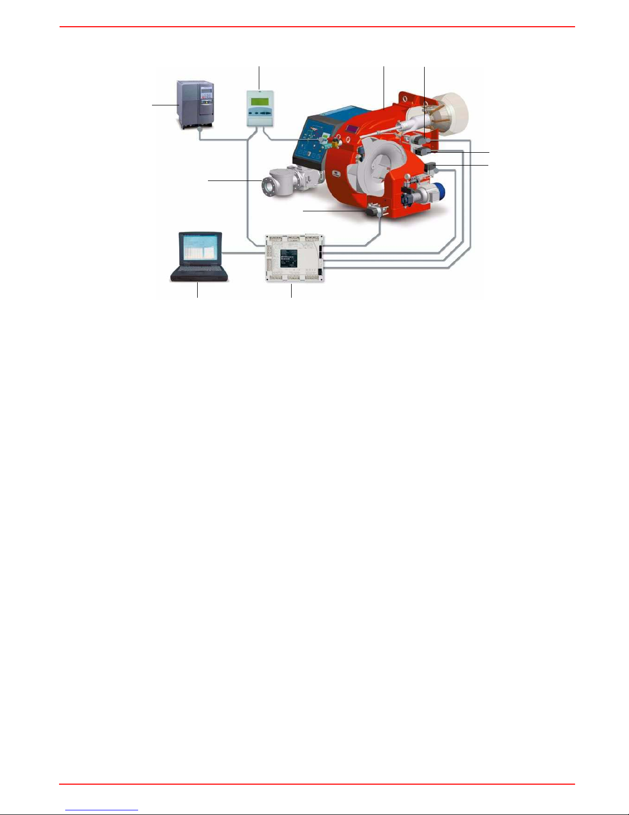
Keys
1 Burner
2 Combustion head actuator
3 Gas butterfly valve actuator
4 Oil pressure governor actuator
5 Air damper actuator
6 Siemens LMV burner control
7 Personal Computer
8Gas train
9Inverter
10 Siemens AZL User interface
The control system is made of the Siemens LMV central unit (6) that performs all the burner control functions and of the Siemens AZL
local programming unit (10) that interfaces the system with the user.
Main features:
z no mechanical linkages
z built-in burner control box
z built-in gas proving system
z more flame checking devices available for several applications
z PID load controller
z up to six actuators can be controlled. Each of them is independent for the best burner setup
z best air/fuel ratio. Repeatability and precision of set adjustments
z Modbus communication
z multilevel password
z settings via PC
z adjustable prepurging time (according to the relevant Standards)
z continuous ventilation
z post purging (adjustable time)
z proving system settable to on and off
z adjustable proving system time for all the valve volumes
z load controller settable to on and off
z thermal shock protection function settable to on and off (for cold starts)
z continuous operation and flame detection probe
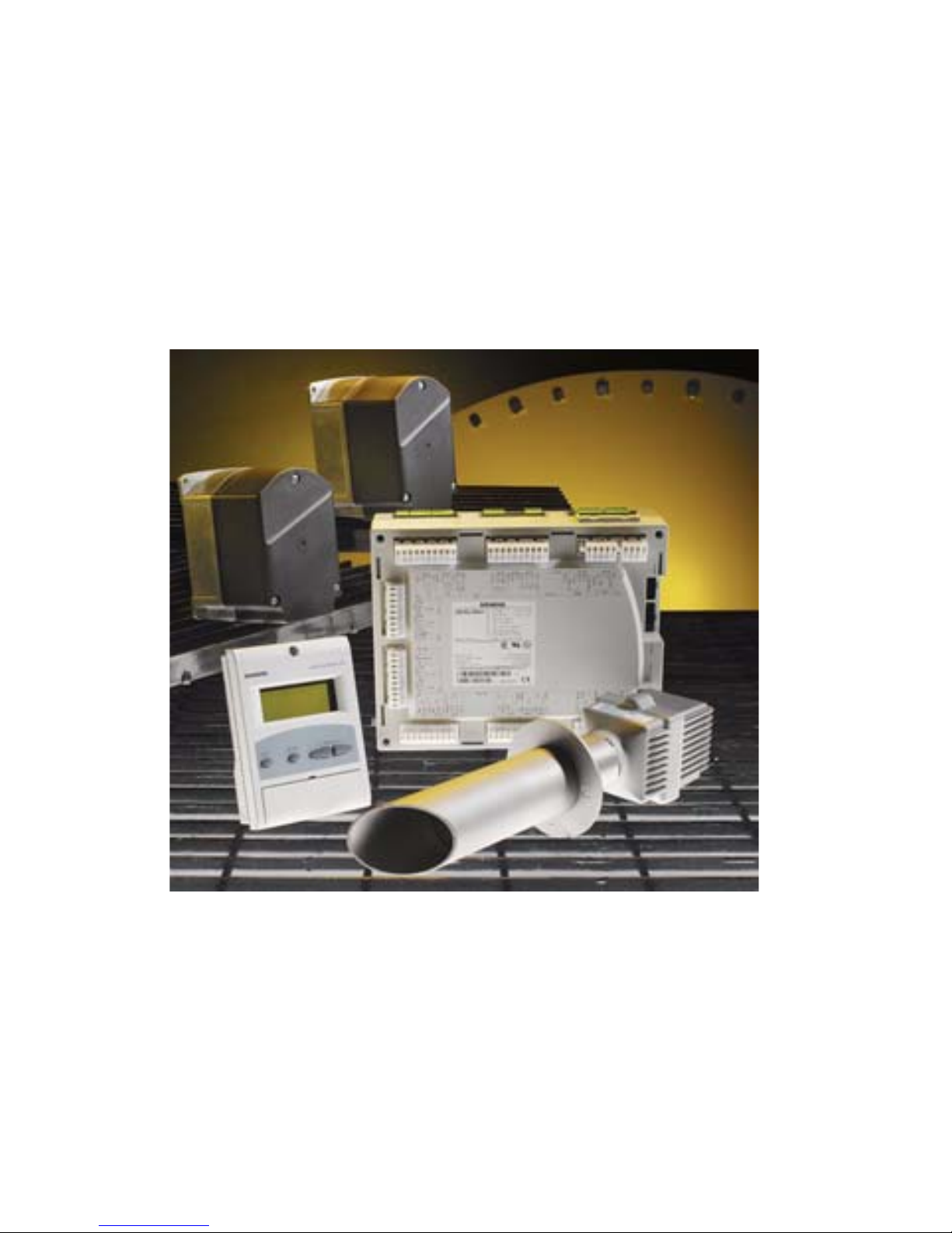
Note: the picture above shows a complete control system.
1
2
3
5
4
6
7
8
9
10
4
USER SETTINGS
Go on adjusting the burner.
Users can set only the LMV parameters that can be accessed without password: (see “Adjusting the temperature set-point”).
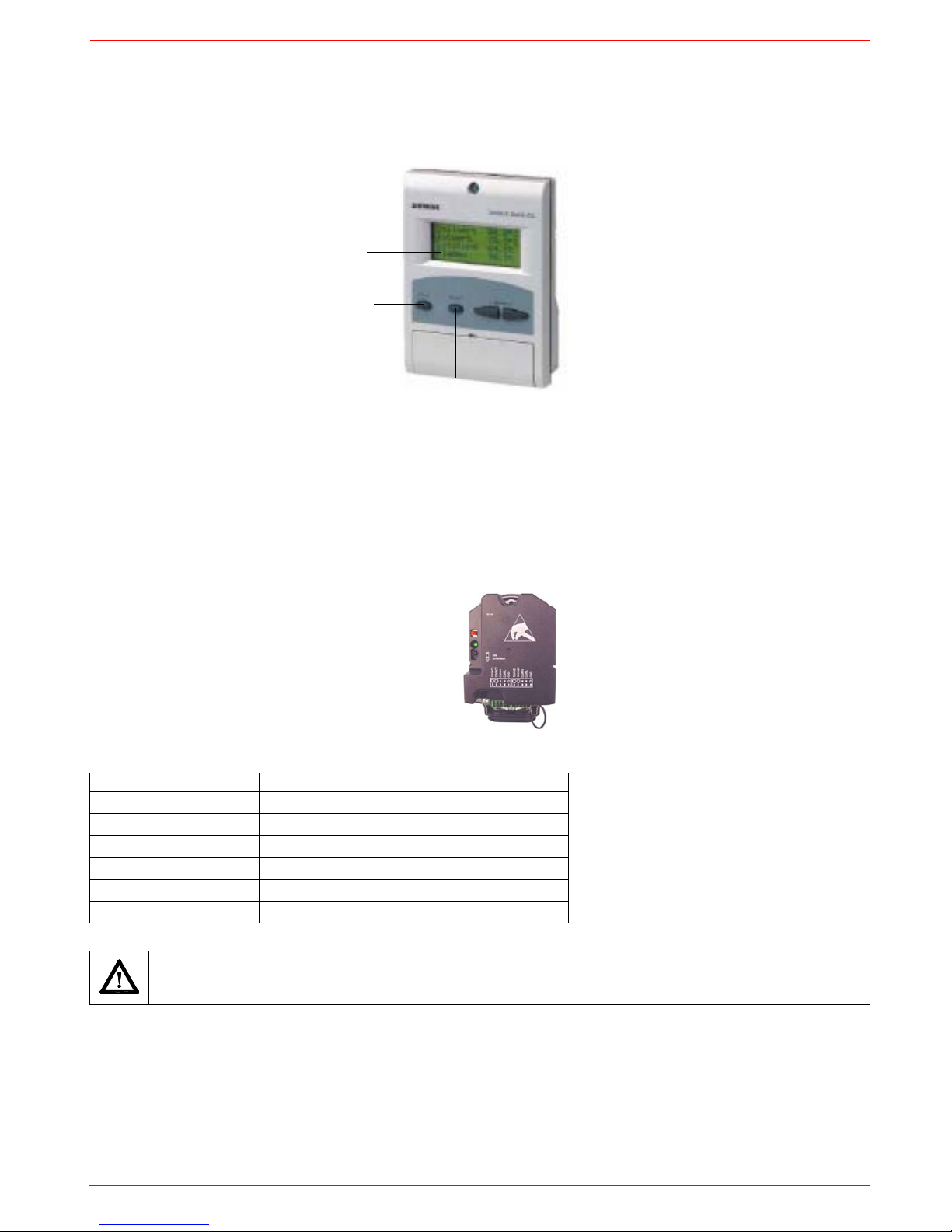
The Siemens AZL User Interface allows programming the Siemens LMV control box and monitoring the system data.
The user interface is made of:
1. display: it showes menus and parameters
2. ESC key (previous level): it goes back to the prevoius level menu or exits the programming mode without changing data.
3. ENTER key (next level): it confirms the data changing and jumps to the next menu/parameter.
4. SELECT keys: they select a menu item and change the parameter values.
To know the actuator functions, proceed as follows:
1 remove the actuator covers
2 check the number of the LV green LED blinks for each actuator:
Blinks Actuator function
1 blink air damper actuator
2 blinks gas butterfly valve actuator
3 blinks oil pressure governor actuator
4 blinks auxiliary actuator
5 blinks auxiliary actuator
6 blinks auxiliary actuator
CAUTION: it is recommended not to adjust the actuators. Anyway, never press the actuator red button, otherwise the fundamental parameters, necessary for the burner operation, will be cancelled. The burner will therefore continuously lock out.
1
2
3
4
LV
5
Start-up procedure
1 Turn the burner on according to the following:
z ual fuel burners: choose the requested fuel by means of the related control panel switch
z one fuel burners: turn the burner on by means of the burner main switch (placed on the burner control panel)
2 the LMV controller starts the system test cycle: the AZL display shows the System Test message; at the end of the test, it shows
the main page and the system stops (the safety chain is open) waiting for the startup enabling signal (standby - Program phase no.
12)
3 check the fan motor rotation;
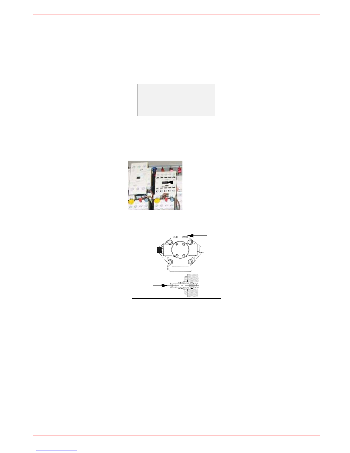
4 (light/heavy oil burners) with the electrical panel open, prime the oil pump acting directly on the related CP contactor (see next pic-
ture): check the pump motor rotation and keep pressing for some seconds until the oil circuit is charged;
5 bleed the air from the M pressure gauge port (see next picture) by loosing the cap without removing it, then release the contactor.
6 make the safety chain enabling the system to start up
7 the combustion cycle starts:
- Prepurging (program phase no.30)
- Driving to ignition position (program phase no.36)
- Ignition position (program phase no.38)
- Fuel (the fuel solenoid valves open)
- Flame (the flame lights up)
- Driving to low flame (the actuator drives to low flame).
NOTE: the C and A, on the .
Once the ignition cycle ends, the main page is shown:
Suntec T..
Main page
Setpoint 80°C
Act value
78°C
Fuel GAS
CP
M
VR
 Loading...