

Siemens LMV52 Series, LMV51.040C2, LMV51.100C1, LMV51.100C2, LMV51.000C1 Series Manual
...
550
7
Burner Management
LMV5...
System
LMV51...
LMV52...
Burner control with integrated fuel / air ratio contro l and load control for us e with
forced draft burners.
Burner control with integrated fuel / air ratio control and load control fo r use with
forced draft burners including oxygen trim control.
The LMV5... and this Data Sheet are intended for use by OEMs which integrate
the burner management systems in their products!
Use
CC1N7550en
24.05.2011
LMV5... is a microprocessor-based burner management system with matching system
components for the control and supervision of forced draft burners of medium to high
capacity.
- For gas burners with and without fan to EN 298: 2003
- For oil burners to EN 230: 2005
Building Technologies Division
Industry Sector

Warning notes
For additional safety notes, refer to the Basic Documentation of the LMV5... system (P7550)!
To avoid injury to persons, damage to property or the environment, the following
warning notes must be observed!
The LMV5... is a safety device! Do not open, interfere with or modify the unit.
Siemens will not assume responsibility for any damage resulting f rom unauthorized interference!
• All activities (mounting, installation and service work, etc.) must be performed by
qualified staff
• Before making any wiring changes in the connection area of the LMV5..., com-
pletely isolate the plant from mains supply (all-polar disconnection). Ensure that the
plant cannot be inadvertently switched on again and that it is indeed dead. If not
observed, there is a risk of electric shock hazard
• Ensure protection against electric shock hazard by providing adequate protection
for the connection terminals and by securing the housing cover
• Each time work has been carried out (mounting, installation, service work, etc.),
check to ensure that wiring and parameterization is in an orderly state and make
the safety checks as described in «Commissioning notes»
• Fall or shock can adversely affect the safety functions. Such units must not be put
into operation, even if they do not exhibit any damage
2/39
Building Technologies Division CC1N7550en
Industry Sector 24.05.2011
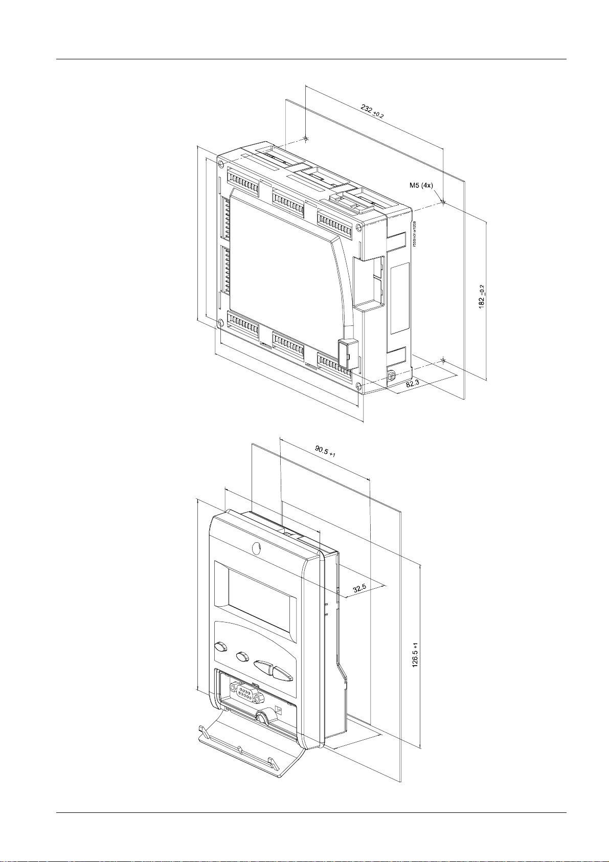
Mounting notes
Notes for mounting LMV5...
• Ensure that the relevant national safety regulations are complied with
M
o
u
n
t
S
i
n
i
z
g
e
p
>
l
a
2
t
e
m
m
200
182
Notes for mounting AZL5...
2
3
2
2
5
0
M
o
u
n
S
t
i
n
i
z
g
e
p
1
l
a
.
5
t
e
.
.
.
4
m
m
132
9
6
9
3
7550m02e/1208
3/39
Building Technologies Division CC1N7550en
Industry Sector 24.05.2011
Installation notes
• Always run high-voltage ignition cables separately while observing the greatest
possible distance to the unit and to other cables
• Do not mix up live and neutral conductors
Electrical connection of the flame detectors
It is important to achieve practically disturbance- and loss-free signal transmission:
• Never run the detector cable together with other cables
– Line capacitance reduces the magnitude of the flame signal
– Use a separate cable
• Observe the maximum permissible detector cable lengths
• The ionization probe is not protected against electric shock hazard. It is mains-
powered and must be protected against accidental contact
• Locate the ignition electrode and the ionization probe such that the ignition spark
cannot arc over to the ionization probe (risk of electrical overloads)
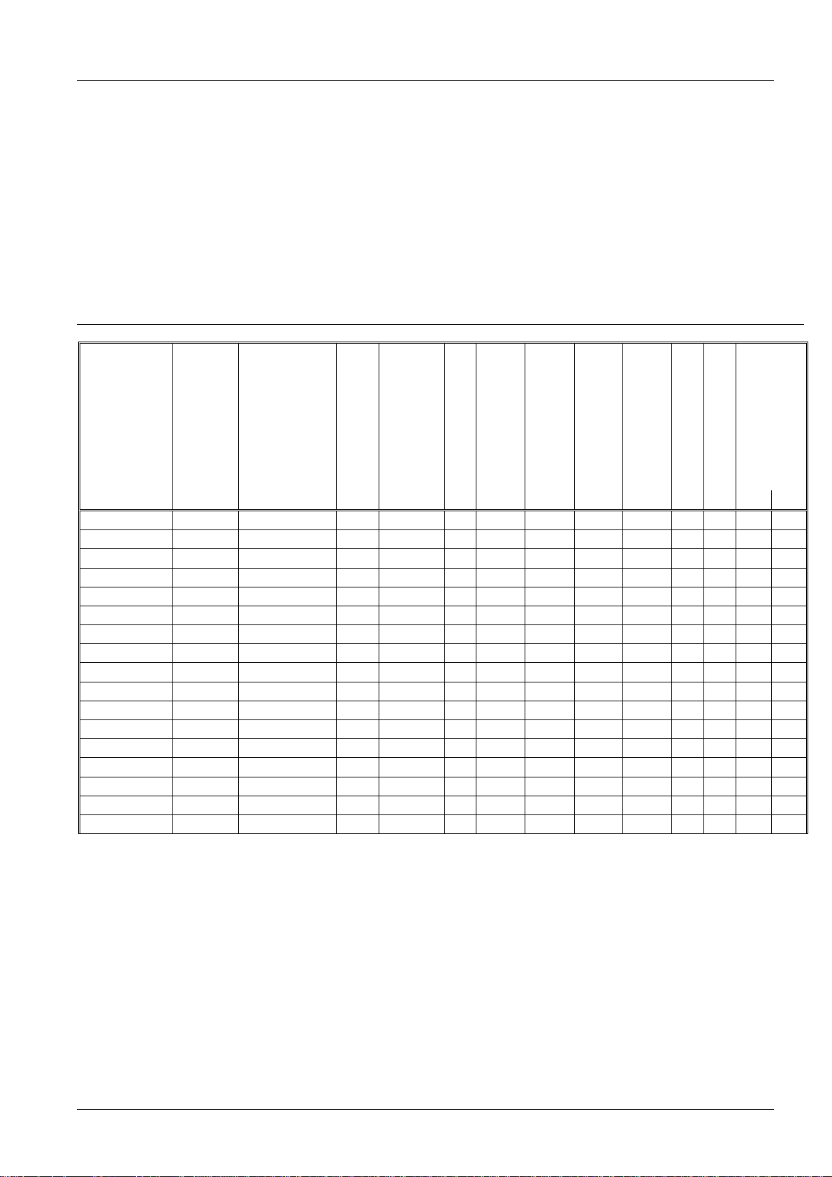
Standards and certificates
Type
LMV51.000C1
LMV51.000C2
z z z
z z z
LMV51.040C1 --LMV51.040C2 --LMV51.100C1
LMV51.100C2
z z z
z z z
LMV51.140C1 --LMV51.140C2 --LMV51.300B1
LMV51.300B2
z z z
z z z
LMV51.340B1 --LMV52.200B1
LMV52.200B2
z z z
z z z
LMV52.240B1 --LMV52.240B2 --LMV52.400B2
z z z
LMV52.440B1 ---
Conformity to EEC directives
- Electromagnetic compatibility EMC (immunity)
- Directive for gas-fired appliances
- Low-voltage directive
- Directive for pressure devices
- Safety limit thermostats
2004/108/EC
2009/142/EC
2006/95/EC
97/23/EEC
to EN 14597
Safety and control devices for gas and/or oil burners and gas and/or
oil appliances - Particular requirements -
Part 1: Fuel/air ratio controls, electronic type ISO 23552-1:2007
ISO 9001: 2010
Cert. 00739
ISO 14001: 2010
Cert. 38233
z
z
z
z
---
--- --- --- ---
---
--- --- --- ---
CSA
--- --- ---
--- --- ---
z z z
z z z
z z z z z z
z z z
--- --- ---
--- --- ---
z z z
z z z
z z z z z z
z z z
--- --- --- --- ---
--- --- --- --- ---
z
z
z
---
z z z
--- --- --- ---
--- --- --- ---
---
z z z
--- --- --- --- ---
--- ---
z z
z z
---
z z
z z
--- --- --- --- ---
z
--- --- --- --- --- ---
z
z
z
z
z
4/39
Building Technologies Division CC1N7550en
Industry Sector 24.05.2011
Supplementary documentation
User documentation AZL5… Modbus......................................................................A7550
User Documentation, basic diagram for LMV5...
with 2 types of gas................................................................................................A7550.1
User Documentation, basic diagram for LMV5...
with 2 types of liquefied fuel..................................................................................A7550.3
Operating Instructions ACS450 PC Software for LMV5... ....................................... J7550
Setting Lists .............................................................................................................. I7550
Fundamentals on Installation LMV5….................................................................. J7550.1
Basic Documentation LMV5….................................................................................P7550
Range Overview LMV5… ....................................................................................... Q7550
Operating Instructions AZL5… (U7550.2) for heating engineer level ......... 74 319 0306 0
Operating Instructions AZL5… (U7550.3) for user level............................. 74 319 0307 0
Service notes
• If fuses are blown, the unit must be returned to Siemens
Life cycle
Burner controls has a designed lifetime* of 250,000 burner startup cycles which, under
normal operating conditions in heating mode, correspond to approx. 10 years of usage
(starting from the production date given on the type field). This lifetime is based on the
endurance tests specified in standard EN 230/EN 298 and the table containing the relevant test documentation as published by the European Association of Component
Manufacturers (Afecor) (www.afecor.org).
The designed lifetime is based on use of the burner controls according to the manufacturer’s Data Sheet and Basic Documentation.
After reaching the designed lifetime in terms of the number of burner startup cycles, or
the respective time of usage, the burner control is to be replaced by authorized personnel.
* The designed lifetime is not the warranty time specified in the Terms of Delivery
Disposal notes
The unit contains electrical and electronic components and must not be disposed of together with domestic waste.
Local and currently valid legislation must be observed.
5/39
Building Technologies Division CC1N7550en
Industry Sector 24.05.2011
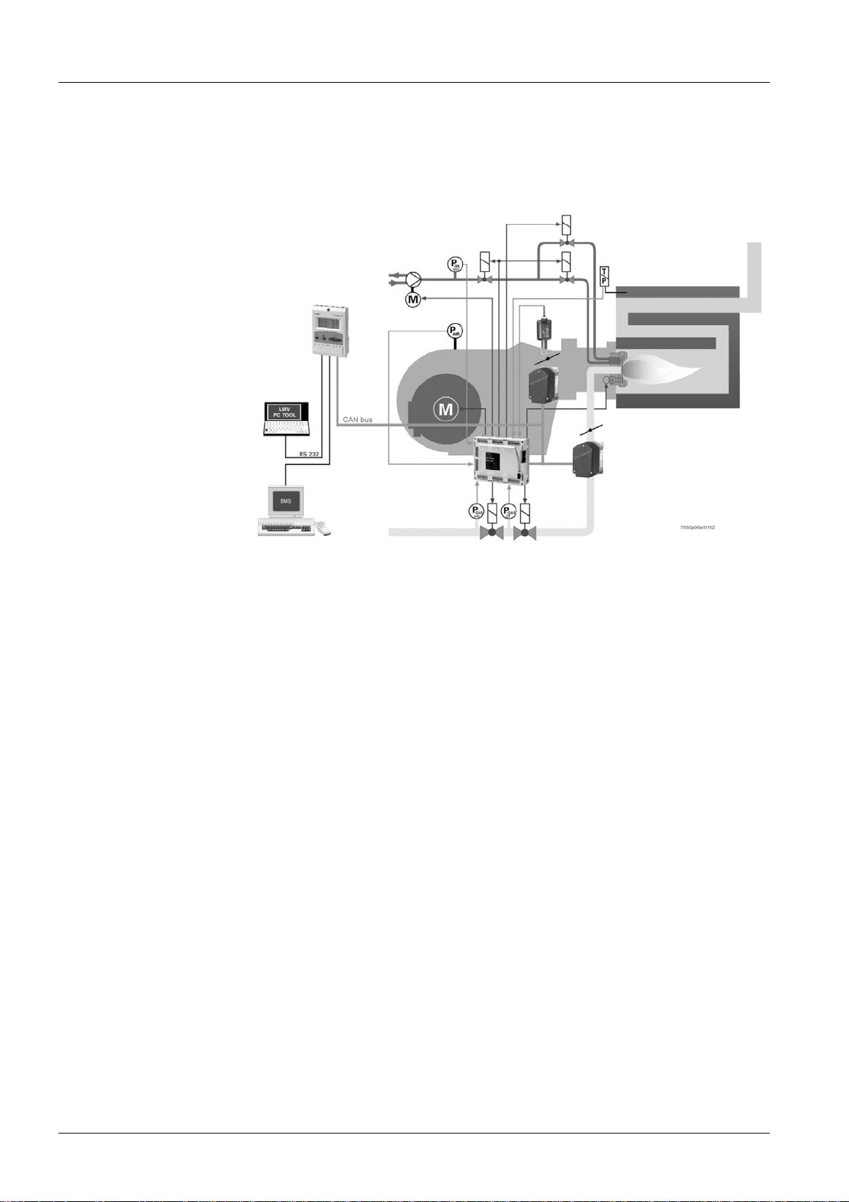
Mechanical design
The following system components are integrated in the basic unit of the LMV5…:
• Burner control with gas valve proving system
• Electronic fuel / air ratio control for use with a maximum of 4 (LMV51…) or 6
(LMV52…) actuators
• Optional PID temperature / pressure controller (load controller)
• Optional variable speed drive module (VSD module)
Example:
Dual-fuel burner
- Gas: Modulating
- Oil: 2-stage
The system components (display and operating unit, actuators and O2 module) are interconnected via a CAN bus system. Communication between the bus users is ensured
via a reliable, system-based data bus. For safety reasons, integration of the bus into
external CAN bus systems is not allowed. All safety-related digital inputs and outputs of
the system are constantly monitored by a contact feedback network (CFN). For flame
supervision in connection with the LMV5... and continuous operation, the QRI... infrared
flame detector, the QRA7... UV flame detector or an ionization probe can be used and,
for intermittent operation, the optical flame detectors type QRB... or QRA2…, QRA4.U,
QRA10… with AGQ1… (AC 230 V).
The burner management system is operated and programmed with the help of the display and operating unit (AZL5...) or a PC tool. The AZL5... features clear-text display
and menu-driven operation, thus offering straightforward operation and targeted diagnostics. To simplify diagnostics, the display shows the operating states, the type of fault
and the point in time the fault occurred. The different parameter setting levels for the
burner / boiler manufacturer and the heating engineer are protected by passwords. Basic settings that the plant operator can make on site do not demand a password. Further, the display and operating unit serves as an interface to higher level systems such
as building automation and control systems (BACS) or a PC which has the ACS450
software installed. Among other features, the unit affords convenient readout of settings
and operating states, parameterization of the LMV5..., and trend logging.
6/39
Building Technologies Division CC1N7550en
Industry Sector 24.05.2011
Mechanical design (cont´d)
2
Type summary
When replacing the LMV5... basic unit (BU), all parameters can be saved in a backup
memory of the AZL5… to be downloaded again when the new unit is installed. Hence,
manual reprogramming is not required.
To design specific fuel trains, the burner / boiler manufacturer can choose from a total
of 7 valve families and – by making use of the large number of parameter setting
choices (programming times, configuration of inputs and outputs, etc.) – fuel trains can
be matched to individual needs.
The SQM4.../SQM9... actuators are driven by stepper motors and offer high-resolution
positioning. The characteristics and settings of the actuators are defined by the LMV5...
basic unit.
Type reference
LMV51.000C1 AC 120 V Europe 4 --- --- ---
LMV51.000C2 AC 230 V Europe 4 --- --- ---
LMV51.040C1 AC 120 V US / Canada 4 --- --- ---
LMV51.040C2 AC 230 V US / Canada 4 --- --- ---
LMV51.100C1 AC 120 V Europe 4
LMV51.100C2 AC 230 V Europe 4
LMV51.140C1 AC 120 V US / Canada 4
LMV51.140C2 AC 230 V US / Canada 4
LMV51.300B1 AC 120 V Europe 5 *)
LMV51.300B2 AC 230 V Europe 5 *)
LMV51.340B1 AC 120 V US / Canada 5 *)
LMV52.200B1 AC 120 V Europe 6
LMV52.200B2 AC 230 V Europe 6
LMV52.240B1 AC 120 V US / Canada 6
LMV52.240B2 AC 230 V US / Canada 6
LMV52.400B
LMV52.440B1 AC 120 V US / Canada
Mains voltage
AC 230 V Europe
Parameter set
Max. num ber of
actuators
Automatic adaptation
of controller’s
characteristics
Limit thermostat
z z
z z
z z
z z
---
---
---
---
z z z z z z z
z z z z z z z
z z z z z z z
z z z z z z z z
z z z z z z z z
z z z z z z z z
z z z z z z z z
6
z z z z z z z z
6
z z z z z z z z
*) When the VSD module is activated, only 4 SQM4.../SQM9... actuators can be
controlled!
Fuel meter input
Integr ated gas valve
proving
Integrated PID load
z
z
z
z
z z
z z
z z
z z
Safety time
TSAmax.
controller
Control of VSD
Analog output
O2 trim control
Gas Oil
--- --- --- --- 3 s 5 s
--- --- --- --- 3 s 5 s
--- --- --- --- 10 s 15 s
--- --- --- --- 10 s 15 s
---
---
---
---
--- 3 s 5 s
z
--- 3 s 5 s
z
--- 10 s 15 s
z
--- 10 s 15 s
z
--- 3 s 5 s
--- 3 s 5 s
--- 10 s 15 s
3 s 5 s
3 s 5 s
10 s 15 s
10 s 15 s
3 s 5 s
10 s 15 s
7/39
Building Technologies Division CC1N7550en
Industry Sector 24.05.2011
Technical data
LMV5... basic unit
Mains voltage AC 120 V
-15% / +10%
Transformer
- Primary side
- Secondary side 1
- Secondary side 2
AGG5.210
AC 120 V
AC 12 V
2 x AC 12 V
AC 230 V
-15% / +10%
AGG5.220
AC 230 V
AC 12 V
2 x AC 12 V
Mains frequency 50 / 60 Hz ±6% 50 / 60 Hz ±6%
Power consumption <30 W (typically) <30 W (typically)
Safety class I, with parts according to II and III to
DIN EN 60730-1
Terminal loading «Inputs»
• Perm. mains primary fuse
Max. 16 AT Max. 16 AT
(externally)
• Unit fuse F1 (internally) 6.3 AT to
DIN EN 60127 2/5
6.3 AT to
DIN EN 60127 2/5
• Mains supply: Input current depending on operating state of the unit
Undervoltage
• Safety shutdown from operating
<AC 96 V <AC 186 V
position at mains voltage
• Restart on rise in mains voltage >AC 100 V >AC 188 V
Oil pump / magnetic clutch
(nominal voltage)
• Nominal c urrent 1,6 A 2 A
• Power factor Cosϕ >0.4 Cosϕ >0.4
LP test valve (nominal voltage)
• Nominal c urrent 0.5 A 0.5 A
• Power factor Cosϕ >0.4 Cosϕ >0.4
Status inputs (KRN): Status inputs (with the exception of the safety loop) of the contact feedback network (CFN) are used for system supervision and require mainsrelated input voltage
• Input safety loop Refer to «Terminal loading outputs»
• Input currents and input voltages
- UeMax
- UeMin
- IeMax
- IeMin
• Contact material recommendation
UN +10%
UN -15%
1.5 mA peak
0.7 mA peak
UN +10%
UN -15%
1.5 mA peak
0.7 mA peak
Gold-plated silver contacts
for external signal sources (LP,
DWmin, DWmax, etc.)
• Transition / settling behavior /
bounce
- Perm. bounce time of contacts
when switching on / off
Max. 50 ms
(after the bounce time, the contact must
stay closed or open)
• UN AC 120 V AC 230 V
• Voltage detection
- On
- Off
AC 90...132 V
<AC 40 V
AC 180...253 V
<AC 80 V
Terminal loading «Outputs»
Total contact loading:
(nominal voltage)
• Unit input current (safety loop) total
Max. 5 A Max. 5 A
contact current from:
- Fan motor contactor
- Ignition transformer
- Valves
- Oil pump / magnetic clutch
8/39
Building Technologies Division CC1N7550en
Industry Sector 24.05.2011
Technical data (cont’d)
&
Cross-sectional areas
Individual contact loading:
Fan motor contactor
• Nominal voltage AC 120 V AC 230 V
• Nominal c urrent 1 A 1 A
• Power factor Cosϕ >0.4 Cosϕ >0.4
Alarm output (nominal voltage)
• Nominal c urrent 1 A 1 A
• Power factor Cosϕ >0.4 Cosϕ >0.4
Ignition transformer (nominal voltage)
• Nominal c urrent 1.6 A 2 A
• Power factor Cosϕ >0.2 Cosϕ >0.2
Fuel valves-gas (nominal voltage)
• Nominal c urrent 1.6 A 2 A
• Power factor Cosϕ >0.4 Cosϕ >0.4
Fuel valves-oil (nominal voltage)
• Nominal c urrent 1.6 A 1 A
• Power factor Cosϕ >0.4 Cosϕ >0.4
Cable lengths
• Mains line Max. 100 m
(100 pF/m)
• HCFN line Max. 100 m
(100 pF/m) ¹)
• Analog line Max. 100 m
(100 pF/m)
• Flame detector Refer to chapter «Technical Data / Flame
supervision»
• CAN bus Total lengths max. 100 m
Note!
¹)
If the cable length exceeds 50 m, additional loads must not be connected to the
status inputs (refer to «Power supply for the LMV5… system»)!
Above a certain cable length, the actuators must be powered by a separate transformer
installed near the actuators.
The cross-sectional areas of the mains power lines (L, N, PE) and, if required, the
safety loop (safety limit thermostat, water shortage, etc.) must be sized for nominal currents according to the selected external primary fuse. The cross-sectional areas of the
other cables must be sized in accordance with the internal unit fuse (max. 6.3 AT).
Min. cross-sectional area
Cable insulation must meet the relevant temperature requirements and conform to the
environmental conditions. The CAN (bus) cables have been specified by Siemens and
can be ordered as accessory items. Other cables must not be used. If t his is not
observed, t he EMC c har act er isti cs of the LMV5... s ystem wi l l b e unpr ed ic t able!
Fuses used in the LMV5... basic unit
- F1 6.3 AT
- F2 4 AT
- F3 4 AT
0.75 mm²
(single- or multi-core to VDE 0100)
DIN EN 60127 2/5
GMD-4A
GMD-4A
Max. 100 m
(100 pF/m)
Max. 100 m
(100 pF/m) ¹)
Max. 100 m
(100 pF/m)
6.3 AT
DIN EN 60127 2/5
4 AT
DIN EN 60127 2/5
4 AT
DIN EN 60127 2/5
9/39
Building Technologies Division CC1N7550en
Industry Sector 24.05.2011
Technical data (cont’d)
AZL5... operating
and display unit
PLL52...
Operating voltage AC 24 V -15% / +10%
Power consumption <5 W (typically)
Degree of protection of housing
- Rear
- Front
IP00 to IEC 529
IP54 to IEC 529 when installed
Safety class I, with parts according to II and III to
DIN EN 60730-1
Battery:
Supplier Type reference
VARTA CR 2430 (LF-1/2 W)
DURACELL DL 2430
SANYO ELECTRIC, Osaka / Japan CR 2430 (LF-1/2 W)
RENATA AG, Itingen / CH CR 2430
Mains voltage «X89-01» AC 120 V
–15% / +10%
Safety class
I, with parts according to II
AC 230 V
–15% / +10%
to DIN EN 60730-1
Mains frequency 50 / 60 Hz ±6% 50 / 60 Hz ±6%
Power consumption Approx. 4 VA Approx. 4 VA
Degree of protection IP54, housing closed
Cable lengths / cross-sectional areas:
• Electrical connection «X89» Screw terminals up to 2.5 mm²
• Cable lengths ≤10 m to QGO20...
AGG5.2…
CAN bus cable
• Cross-sectional areas Refer to QGO... description, twisted pairs
Analog inputs:
• Supply air temperature sensor Pt1000 / LG-Ni1000
• Flue gas temperature sensor Pt1000 / LG-Ni1000
• QGO20... Refer to Data Sheet N7842
• Interface Communication bus for LMV52...
Transformer AGG5.220
- Primary side
- Secondary side
Transformer AGG5.210
- Primary side
- Secondary side
AC 230 V
AC 12 V (3x)
AC 120 V
AC 12 V (3x)
Cable types:
AGG5.641 8 mm dia. ±0.2 mm
Bending radius ≥120 mm
Ambient temperature -30...+70°C
(no movements of cable)
Cable is resistant to almost all types of
mineral oil
AGG5.631 7.5 mm dia. ±0.2 mm
Bending radius ≥113 mm
Ambient temperature -30...+70°C
(no movements of cable)
Cable is resistant to almost all types of
mineral oil
10/39
Building Technologies Division CC1N7550en
Industry Sector 24.05.2011
Technical data (cont’d)
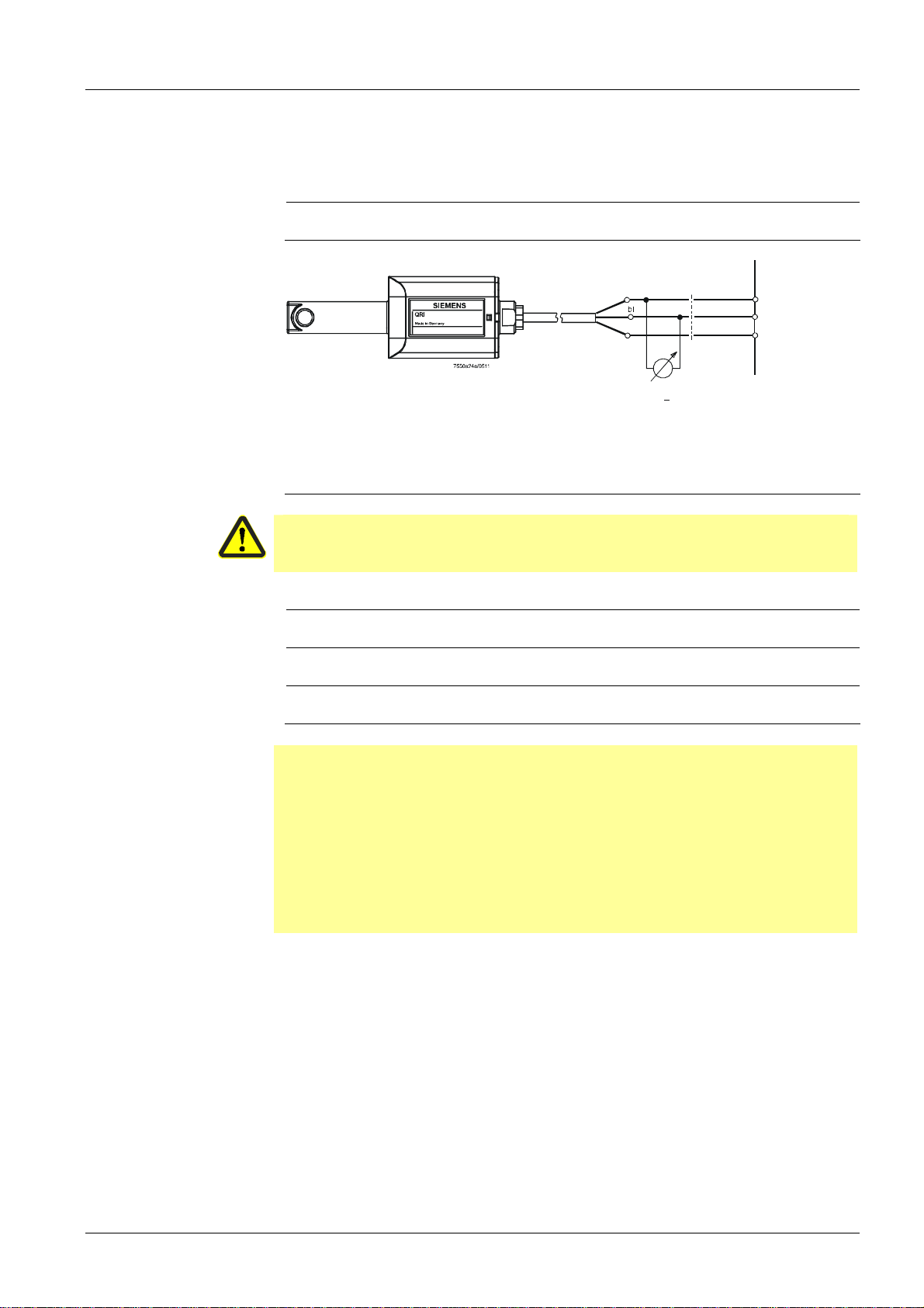
Flame supervision
QRI (suited for
continuous operation)
Connection diagram
IONIZATION (suited for
continuous operation)
&
Note:
All measured voltages refer to connection terminal N (X10–02, terminal 4).
Supply voltage operation / test at termi-
Approx. DC 14 / 21 V
nal POWER QRI... (X10–02, terminal 2)
Minimum signal voltage required at terminal FSV / QRI... (X10–02, terminal 6)
Min. DC 3,5 V
Display flame approx. 50 %
LMV...
sw
br
+
0...10 V
Ri 10 M>
For detailed information, refer to Data Sheet N7719.
No-load voltage at terminal ION (X10–
Approx. UMains
03, terminal 1)
Caution!
The ionization probe must be installed such that protection against electrical
shock hazard is ensured!
Short-circuit current Max. AC 0,5 mA
Required detector current Min. DC 6 µA
Display flame approx. 50 %
Possible detector current Max. DC 85 µA
Display flame approx. 100 %
Permissible length of detector cable
(lay separately)
100 m
(wire-earth 100 pF/m)
Note!
The greater the detector cable capacitance (cable length), the lower the voltage at the
ionizations probe and, therefore, the lower the detector current. In the case of extensive cable lengths and high-resistance flames, it may be necessary to use lowcapacitance cables (e.g. ignition cable). The electronic circuit is designed such that
impacts of the ignition spark on the ionization current will be largely eliminated. Nevertheless, it must be ensured that the minimum detector current required will already be
reached during the ignition phase. If that is not the case, the connections of the ignition
transformer on the primary side must be changed and / or the location of the electrodes also.
X10-02 / 6 Signa l
X10-02 / 4 N
X10-02 / 2 Power supply
and test
11/39
Building Technologies Division CC1N7550en
Industry Sector 24.05.2011
Technical data (cont’d)
Flame supervision
QRA2… / QRA4.U /
QRA10… with
AGQ1…A27
&
QRA…
LMV5…
AGQ1…A27
Connection diagram
For intermittent operation only.
Note!
AGQ1… is only available for AC 230 V mains voltage.
Power supply in operation DC 280…325 V
Power supply in test mode DC 390…750 V
For more detailed information about QRA2… / QRA10…, refer to Data Sheet N7712.
For more detailed information about QRA4.U, refer to Data Sheet N7711.
Caution!
QRA2… (QRA4.U / QRA10... must not be used when extraneous light supp ression is activated since detector tests will not be made in that case!
Possible ionization current Max. 10 µA
Ionization current required Min. 6 µA
In connection with the LMV5…, ancillary unit AGQ1…A27 must be used.
Power supply AC 230 V
Possible current Max. 500 µA
Current required Min. 200 µA
LMV5...
X10-02 / 3
7550a 20/03 08
X10-02 / 4
X3-01 / 1
X10-03 / 1
Assignment of LMV5…terminals:
X10-02 / 3 L
X10-02 / 4 N
X10-03 / 1 Ionization
X3-01 / 1 Fan
bl
br
QRA
When laid together with other cables (e.g. in a cable duct), the length of the 2-core cable between QRA… and AGQ… must not exceed 20 m. A maximum cable length of
100 m is permitted if the 2-core cable is run at a distance of at least 5 cm from other
live cables. The length of the 4-core cable between AGQ… and LMV5… is limited to
20 m. A maximum cable length of 100 m is permitted if the signal line (ionization /
black) is not run in the same cable but separately at a distance of at least 5 cm from
other live cables.
12/39
Building Technologies Division CC1N7550en
Industry Sector 24.05.2011
rt
sw
sw
AGQ1...A27
bl
 Loading...