

Page 1
HVAC Products
LMU54... / LMU64...
Boiler Management Unit (BMU)
Basic Documentation
Software version 2. 08
CC1P7494en
07.11.2002
Siemens Building Technologies
Page 2

Safety notes
Caution: The present Basic Documentation describes the broad range of applications and functions
offered by the LMU... and shall serve as a guideline. The correct functioning of the unit must
be checked and confirmed by functional tests on the boiler and / or on the relevant plant!
• Degree of protection IP 40 to EN 60 529 for burner controls must be ensured by the burner or boiler
manufacturer by adequately mounting the LMU...
• In the geographical areas where DIN standards apply, mounting and installation must be in compliance
with the relevant VDE requirements, especially DIN / VDE 0100, 0550 and DIN / VDE 0722!
• The electrical wiring inside the boiler must conform to country-specific and local regulations!
• Where (S)LTs are required, refer to the safety-related notes given in section «Electronic (S)LT»!
• It must be ensured that spliced individual wires cannot get in contact with adjacent terminals.
Use adequate ferrules!
• Prior to commissioning, check wiring and parameterization carefully!
The boiler manufacturer is responsible for the correct parameterization of the LMU..., which must be in
compliance with the relevant standards and regulations!
• When commissioning the plant, check all safety functions!
• Before performing any wiring changes or other work in the connection area of the LMU…, completely
isolate the unit from the mains supply!
• Lay high-voltage ignition cable completely separate from all other cables!
• Ensure protection against electric shock hazard on the LMU… and on all electrical connections
through appropriate mounting!
• There is no absolute protection against incorrect use of the RAST5 connectors.
For this reason, check the correct connector assignments prior to commissioning the plant!
• The burner manufacturer must ensure protection against electric shock hazard on all AC 230 V terminals
by fitting dummy plugs!
• When wiring the unit, AC 230 V mains voltage and extra low-voltage must always be run strictly
separate to warrant protection against electric shock hazard!
− DIN EN 60335
− DIN EN 60730-2-5
• Protect the mains-powered ionization probe against electric shock hazard!
The LMU… is a safety device!
• Do not open, interfere with or modify the unit!
• Siemens is not liable for damage resulting from unauthorized interference!
• In the event of blown fuses inside the LMU..., return the unit to Siemens!
(Customer may replace mains fuse F1 only once)
• Electromagnetic emissions must be checked on an application-specific basis!
To ensure the safety and reliability of the LMU..., the following points must also be observed:
− Condensation, formation of ice and ingress of water are not permitted!
If such conditions have occurred, make certain the unit is completely dry before switching on!
− Static charges must be avoided as they can damage the unit’s electronic components when touching them
Recommendation: Use ESD equipment !
2/171
Siemens Building Technologies Basic Documentation LMU54... / LMU64... CC1P7494en
HVAC Products 07.11.2002
Page 3

Contents
1 Overview ..........................................................................................10
− Brief description..........................................................................10
1.1 System concept ..................................................................................10
1.2 Features............................................................................................11
− Safety functions ..........................................................................11
− Supervision / protective functions for the plant .................................11
− Auxiliary modules (clip-in) .............................................................11
− DHW .........................................................................................12
− Heating circuit.............................................................................12
− System application ......................................................................12
− Operation / service......................................................................12
− Parameterization.........................................................................13
− Mains transformer........................................................................13
− Other features .............................................................................13
1.3 Product range.....................................................................................13
1.4 Field of use ........................................................................................13
− Target market .............................................................................13
− Heating plants .............................................................................13
− Heat generating equipment ...........................................................13
1.5 Notes on product liability......................................................................14
1.6 Notes on environmental protection........................................................14
− Disposal notes ............................................................................14
2 Product range overview ....................................................................15
3 Functions ..........................................................................................17
3.1 Burner control ....................................................................................17
− Program selection .......................................................................17
− EEPROM...................................................................................17
− Forced intermittent operation ........................................................17
− Burner control program ................................................................17
− Sequence diagram ......................................................................18
− Capacity range < 70 kW ............................................................18
− Capacity range 70...120 kW.......................................................18
− Capacity range > 120 kW..........................................................19
− Description of sequence diagrams..............................................19
− Sequence times.......................................................................20
− Standby..................................................................................20
− Startup ...................................................................................20
− Shutdown................................................................................22
− Home run ................................................................................22
− Special cases (deviations).........................................................22
− LMU... plausibility checks of the speed parameters .......................24
− Parameterization of speed feedback signal..................................24
− Fan parameters accessible via QAA ...........................................25
− The different capacity ranges .....................................................26
− Setting the fan parameters during startup and shutdown................27
− Speed readjustment .................................................................28
3.2 Selection of the compensation variants..................................................30
3/171
Siemens Building Technologies Basic Documentation LMU54... / LMU64... CC1P7494en
HVAC Products Contents 07.11.2002
Page 4

− Heating circuits ...........................................................................30
− Room setpoint ............................................................................ 32
− Configuration of the heating circuits ...............................................34
− DHW circuit................................................................................ 35
3.3 Acquisition of actual values .................................................................. 37
− Assignment of analog sensors ...................................................... 37
− Temperatures ............................................................................. 37
− Display of ionization current ..........................................................38
3.4 Supervisory functions .......................................................................... 39
− Temperature limiter function......................................................... 39
− Flue gas temperature supervision.................................................. 39
− Plausibility check of sensor ....................................................... 39
− Function................................................................................. 39
− Electronic (S)LT ..........................................................................40
− Handling faults ........................................................................ 40
− Flow switch / water pressure supervision ........................................42
− Function of flow switch.............................................................. 42
− Function of pressure switch....................................................... 42
− Pressure sensor.......................................................................... 42
− Static supervision..................................................................... 43
− Dynamic supervision ................................................................ 44
− Load limitation............................................................................ 45
− Speed limitation.......................................................................... 48
− Limitation of ionization current....................................................... 48
3.5 Boiler control...................................................................................... 49
− Frost protection for the boiler........................................................ 49
− Controller delay .......................................................................... 49
− Controller delay due to parameterization..................................... 49
− Controller delay due to SLT criterion........................................... 50
− Controller configuration ................................................................50
− Transfer of setpoint / actual value ...............................................50
− Determining the controller coefficients ........................................ 50
− Heat output limits..................................................................... 51
− Boiler temperature control............................................................ 52
− 2-position control ..................................................................... 52
− Minimum boiler pause time........................................................ 52
− Boiler cycling protection............................................................... 52
− Dynamic switch-off differential.................................................... 53
− Modulating control, conventional................................................ 54
3.6 Hydraulic system management (HSM)................................................... 55
− Frost protection for the plant ......................................................... 55
3.7 Consumer management (CM) .............................................................. 56
− Determining the demands for heat .................................................56
− Priorization of demands for heat ................................................ 56
− Determining the temperature demand............................................ 57
− Temperature limitation ..............................................................58
− Summer / winter (S / W) changeover.............................................. 59
3.8 Electronically controlled PWM heating circuit pump .................................61
− General...................................................................................... 61
− Introduction................................................................................ 61
− Notes ..................................................................................... 61
4/171
Siemens Building Technologies Basic Documentation LMU54... / LMU64... CC1P7494en
HVAC Products Contents 07.11.2002
Page 5

− Task of ∆T control with PWM pump ...............................................61
− First stage Maximum limitation of the flow temperature..................62
− Second stage ∆T limitation........................................................62
− Third stage ∆T supervision ........................................................63
− PWM pump control......................................................................63
− H-Q chart (example) .................................................................63
− Adaption of modulating pump to the heating plant.........................64
− Parametes of the PWM pump (OEM).............................................64
− Preset parameters .......................................................................64
− Activation of PWM pump via a configuration byte.............................65
− Parameters of the PWM pump (installer) ........................................66
− Parameters for temperatures ........................................................66
− PID controller coefficients of delta-T supervision ..............................67
− Summary of all ∆T parameters ......................................................67
− Behavior in different operating modes ............................................68
− Pump overrun..........................................................................68
− Normal operation (heating operation) ..........................................68
− Reduced (setback) operation .....................................................68
− Shutdown mode.......................................................................68
− Heating up phase.....................................................................68
− DHW operation ........................................................................69
3.9 Heating circuit control..........................................................................70
− Attenuated outside temperature .................................................70
− Composite outside temperature ...................................................71
− Type of building construction .....................................................71
− Heating curves .........................................................................72
− Generating the demands for heat ..................................................73
− Time switch.............................................................................74
− Room thermostat .....................................................................75
− RU .........................................................................................75
− Combinations of RU and room thermostat / time switch.................76
− ECO functions ............................................................................77
− S / W changeover.....................................................................77
− Automatic 24-hour heating limit ..................................................77
− Quick setback constant (KON) ......................................................78
− Generating the temperature demands .............................................78
− With fixed value control or emergency operation...........................78
− With weather compensation.......................................................78
4 Clip-in AGU2.500... for additional heating circuit.................................79
− Functions ...................................................................................79
− General...................................................................................79
− Hydraulic diagrams......................................................................79
− Sensor inputs (analog inputs)........................................................79
− Inputs / outputs...........................................................................79
− Interfaces for the LMU... ...............................................................80
− Sensor.......................................................................................80
− Frost protection ...........................................................................80
− Overtemperature protection..........................................................80
− Mixing circuits..........................................................................80
− Determining the flow temperature setpoint ......................................80
− Handling the locking signal........................................................80
5/171
Siemens Building Technologies Basic Documentation LMU54... / LMU64... CC1P7494en
HVAC Products Contents 07.11.2002
Page 6

− Handling the forced signal......................................................... 80
− Flow temperature control.............................................................. 80
− Pump control.............................................................................. 81
− Pump control with pump circuits .................................................81
− Pump control with mixing circuits ............................................... 81
− Pump overrun ..........................................................................81
− Pump kick............................................................................... 81
− Mixing valve control .....................................................................81
− Position of mixing valve in the idle state...................................... 81
− Functional test ............................................................................ 81
5 Clip-in module OCI420... for communication via LPB.......................... 82
− Functions ................................................................................... 82
− General .................................................................................. 82
− Inputs / outputs ...........................................................................82
− Interfaces to LMU... .....................................................................82
5.1 Connection of LMU... to ALBATROS via OCI420 (LPB clip-in) .................. 82
5.1.1 Additional heating circuit extensions via ALBATROS controllers................ 82
− Automatic changeover of operating mode .......................................83
− Giving consideration to heat demand from the RVA… ......................83
− Locking and forced signals when connecting to the LPB................... 83
5.1.2 External DHW heating by ALBATROS controllers ................................... 83
− Type of priority of DHW heating .................................................... 84
5.1.3 Multiboiler plants with LMU (cascade applications).................................. 84
− Separate DHW circuit in cascade applications................................. 85
− Operation with the RVA65... ......................................................... 85
5.1.4 System functions ................................................................................ 86
− Uniform system time.................................................................... 86
− Error / diagnostic messages from the LMU...................................... 86
− Outside sensor, outside temperature sensor................................... 88
− Assignment of address numbers................................................ 88
− Setting the LPB device and segment address................................. 88
6 Clip-in function module AGU2.51x ..................................................... 89
− Functions ................................................................................... 89
− General .................................................................................. 89
− Outputs...................................................................................... 89
− Number of available outputs ......................................................89
− Inputs........................................................................................ 90
− Digital input ............................................................................. 90
− Analog input ............................................................................ 90
− Predefined setpoint (temperature demand) ..................................90
− Predefined output .................................................................... 91
− Sensor input “Pressureless header”............................................ 91
7 DHW control (BWR) .......................................................................... 93
− Boiler temperature setpoint during DHW heating with storage tank
systems ..................................................................................... 93
− DHW temperature control............................................................. 94
− Compensation variants............................................................. 94
− Position of diverting valve.......................................................... 95
− Storage tank systems............................................................... 95
− Stratification storage tank.......................................................... 96
6/171
Siemens Building Technologies Basic Documentation LMU54... / LMU64... CC1P7494en
HVAC Products Contents 07.11.2002
Page 7

− Instantaneous DHW system ........................................................ 100
− Notes ................................................................................... 100
− Hydraulic diagram.................................................................. 100
− Operating mode........................................................................ 100
− Outlet temperature control (FS-DHW is closed).......................... 100
− Comfort control (after FS-DHW opening)................................... 100
− Aqua-booster system.................................................................. 103
− Hydraulic diagram.................................................................. 103
− Operating mode........................................................................ 103
− Outlet temperature control .......................................................103
− Comfort control ......................................................................103
− Legionella function .................................................................... 104
7.1 Special functions .............................................................................. 105
− Forced signals .......................................................................... 105
− Parameterization....................................................................... 105
− Via PC tool ACS420 and OCI490... .......................................... 105
− Via QAA73... / AGU2.310........................................................ 105
− Via AGU2.361 / AGU2.303...................................................... 106
− Programmable input of the LMU... ............................................... 106
− Modem function..................................................................... 106
− Warm air curtain function ........................................................ 106
− Programmable output of the LMU... ............................................. 107
− Status output......................................................................... 107
− Alarm output ..........................................................................107
− Operational status signal......................................................... 107
− Switching off the external transformer ....................................... 108
− Pump output second heating circuit.......................................... 108
− DHW circulating pump............................................................ 108
− Actuating device with warm air curtain function activated............. 108
− Pump of pressureless header .................................................. 108
− Basic function of controller clip-in module.................................. 108
− Actuating device with full DHW charging activated...................... 108
− Actuating device when analog signal exceeds threshold ..............109
− Power concept.......................................................................... 109
8 Basic diagram................................................................................. 110
8.1 LMU... ............................................................................................. 110
9 Connection diagrams...................................................................... 111
9.1 LMU... ............................................................................................. 111
9.2 DHW stepper motor (bipolar).............................................................. 112
9.3 AGU2.104A109................................................................................ 112
9.4 AGU2.500A109................................................................................ 113
9.5 AGU2.500A209................................................................................ 114
9.6 OCI420A109 .................................................................................... 115
9.7 OCI420A209 .................................................................................... 116
9.8 AGU2.51x ........................................................................................ 117
9.9 Connecting cable between OCI490... and PC .......................................118
9.10 Mounting, electrical installation and service.......................................... 119
− Mounting (general) .................................................................... 119
− Mounting the LMU5x............................................................... 119
7/171
Siemens Building Technologies Basic Documentation LMU54... / LMU64... CC1P7494en
HVAC Products Contents 07.11.2002
Page 8

− Ignition device...........................................................................119
− Terminals and wiring .................................................................119
− Testing by the customer.............................................................120
10 Technical data ................................................................................121
10.1 LMU................................................................................................121
− General....................................................................................121
− Electrical connection data ........................................................... 122
− Cable lengths (LMU... Ö HMI and LMU... Ö Clip-in).................126
− Connectors ..............................................................................126
10.2 Clip-in .............................................................................................127
10.2.1 AGU2.500........................................................................................127
− Outputs....................................................................................127
− Electrical connections................................................................127
− Input........................................................................................127
10.2.2 AGU2.51x........................................................................................127
− Outputs....................................................................................127
− Electrical connections................................................................127
− Input........................................................................................127
10.3 External components ........................................................................128
− RAST5 connectors ....................................................................128
− Mains transformer .....................................................................128
− Fan with DC 24 V motor.............................................................128
− Fan with DC motor operating on mains voltage..............................128
11 Dimensions....................................................................................129
11.1 LMU5x... .........................................................................................129
11.2 LMU6x... .........................................................................................130
11.3 AGU2.500A109 / AGU2.51xA109 .......................................................131
11.4 AGU2.500A209................................................................................132
11.5 OCI420A109....................................................................................133
11.6 OCI420A209....................................................................................134
11.7 Mounting plate for clip-in module ........................................................135
12 Parameter list / legend of parameter bit fields LMU... ........................ 136
12.1 Parameter list...................................................................................136
− Parameter list LMU....................................................................136
− Temperatures........................................................................136
− Switching differentials.............................................................137
− Controller functions ................................................................137
− Controller times .....................................................................138
− Controller coefficients.............................................................138
− Pressures .............................................................................138
− Burner control fan ..................................................................139
− Burner control sequence.........................................................139
− Burner control identification.....................................................140
− Operating data......................................................................140
− MCI......................................................................................140
− LPB .....................................................................................140
12.2 Lockout position storage....................................................................141
− Phase designations / numbers ....................................................141
8/171
Siemens Building Technologies Basic Documentation LMU54... / LMU64... CC1P7494en
HVAC Products Contents 07.11.2002
Page 9

12.3 Legend of parameter bit fields LMU..................................................... 142
− Controller functions ................................................................ 142
− Burner control program........................................................... 145
− Operating modes ................................................................... 147
− LPB...................................................................................... 147
13 Glossary of abbreviations ................................................................148
− Constants................................................................................. 148
− Variables.................................................................................. 148
14 Addendum: Hydraulic diagrams BMU............................................... 149
14.1 Hydraulic diagrams ........................................................................... 149
− Basic diagrams......................................................................... 149
− Pump circuit extensions via AGU2.500......................................... 151
− Mixing circuit extensions via AGU2.500... ..................................... 153
− Zone extensions........................................................................ 156
− Heat generation manager........................................................... 162
14.2 Assignment of hydraulic diagrams to the outputs of the LMU…............... 166
9/171
Siemens Building Technologies Basic Documentation LMU54... / LMU64... CC1P7494en
HVAC Products Contents 07.11.2002
Page 10
1 Overview
Brief description
QAA73...
LMU... are Boiler Management Units (BMUs) of digital design for use with gas-fired
appliances equipped with premix burners.
They are used for the startup, control and supervision of premix burners having the
capacity ranges < 70 kW, 70 - 120 kW or > 120 kW in intermittent operation and with
direct ignition of the main flame.
The LMU... provide all supervisory and control functions required for burner, heating and
DHW operation and make possible modular system extensions via integrated
communication interfaces.
Output modulation is accomplished via a PWM-controlled fan, and pneumatic fuel / air
ratio control with the help of a gas valve.
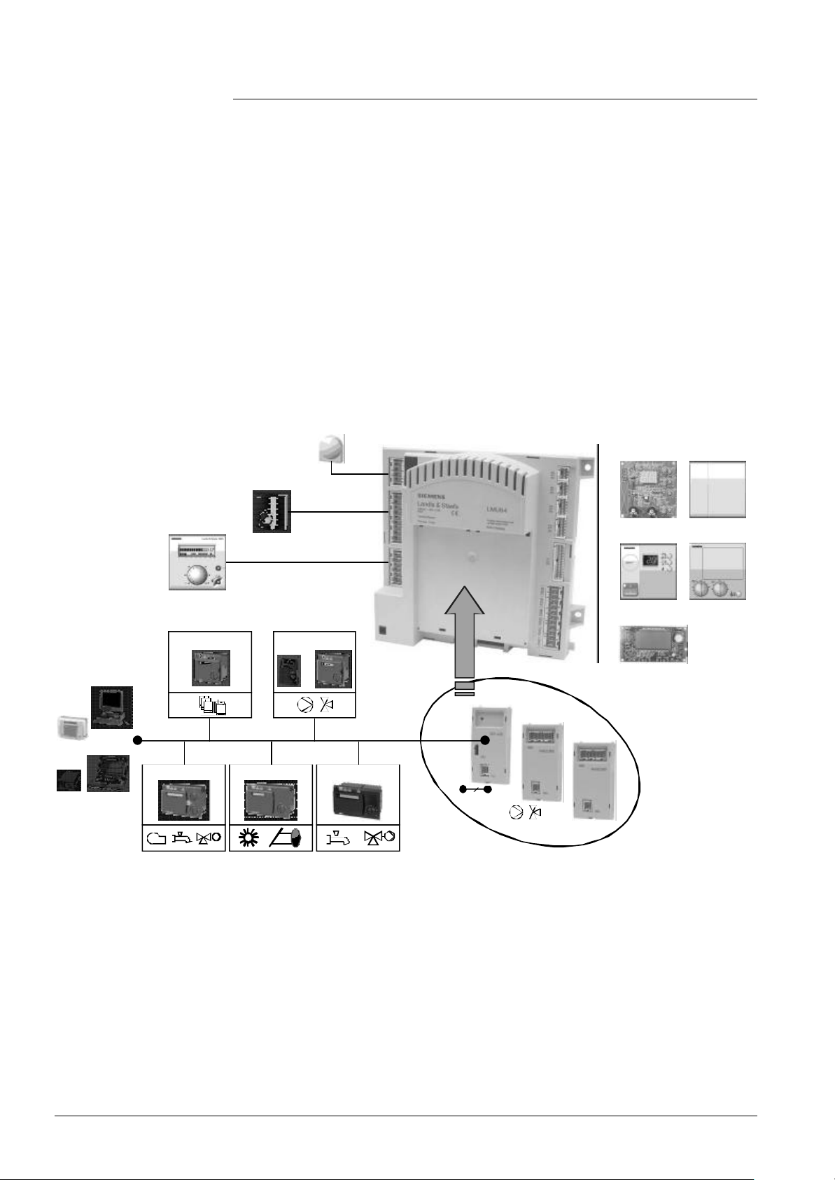
1.1 System concept
LMU...
QAC34...
Room thermostat /
time switch
Human Machine Interface
AGU2.303...
(HMI)
AGU2.350...
Building automation /
remote management
OCI / ACS
Service tool
Modulating room unit
RVA47... RVA46...
LPB
RVA65...RVA63... RVA66...
LPB
Clip-in
Auxiliary modules
OCI420
AGU2.500
AGU2.51x
0...10 V
4...20 mA
AGU2.361...
AGU2.310...
AGU2.362...
7494b01E/0702
10/171
Siemens Building Technologies Basic Documentation LMU54... / LMU64... CC1P7494en
HVAC Products 1 Overview 07.11.2002
Page 11

1.2 Features
Below, the full functionality of the LMU... is described. For information on the scope of
functions of a specific unit, refer to the relevant version / configuration.
Safety functions
Supervision / protective
functions for the plant
• Gas burner control conforming to EN 298 for intermittent operation
• Integrated boiler / burner control for space heating and DHW operation
• Sequence control depending on the boiler’s capacity: < 70 kW, 70 - 120 kW, or > 120 kW.
Boiler capacities up to about 600 kW can be handled (depending on the type of fan /
gas valve used)
• Integrated electronic (safety) limit thermostat
• Integrated limit thermostat function
• Direct ignition of the main flame by means of
− integrated single-pole high-voltage ignition (with the choice of single-electrode
operation)
− external AC 230 V ignition control (optional)
• Continuous (analog) ionization current supervision with optional indication of flame
intensity
• Gas valve control AC 230 V (RAC optional)
• Number of start repetitions can be programmed
• Quick startup (especially in connection with instantaneous DHW systems)
• Fan supervision
• Optimization of combustion (optional)
• Control of an AC 230 V fan (DC 24 V fan optional)
• Ignition load precontrol via speed readjustment
• Adaptive postpurge level of fan speed
• Load limitation (fan limitation by minimum / maximum speed and / or flame signal)
• Number of fan feedback pulses can be selected
• Flame stabilization time
• Boiler cycling protection via minimum boiler off time
• Dynamic switch-off differentials for space heating (Hz) and DHW (Bw) operation
• Pump and diverting valve kick
• Frost protection functions for the plant, the boiler, DHW and the room
• Water pressure supervision (pressure sensor with static and / or dynamic supervision,
contact for pressure switch, flow switch)
• Flue gas temperature supervision
Auxiliary modules
(clip-in)
• OCI420 clip-in for communication, LPB interface for ALBATROS system world
• AGU2.500 clip-in for additional heating circuit
• AGU2.51x clip-in function module
- inputs: NTC, 10 kΩ
digital input
0(4)...20 mA
DC 0...10 V
- outputs: max. 3 relays AC 230 V
11/171
Siemens Building Technologies Basic Documentation LMU54... / LMU64... CC1P7494en
HVAC Products 1 Overview 07.11.2002
Page 12

DHW
• Integrated DHW systems with specific algorithms for storage tank, stratification
storage tank, instantaneous and aquabooster systems
• Instantaneous DHW heating systems with optional comfort function
• DHW heating with charging pump / diverting valve
• Diverting valve control via stepper motor control, N.O. contact with continuous phase
or changeover contact
• DHW control with sensor or thermostat
• Control of DHW circulating pump with QAA73...-V1.4
Heating circuit
System application
• Integrated weather-compensated pump heating circuit
• PWM-controlled heating circuit pump with specific algorithms to ensure most effective
condensation, improved overall efficiency and enhanced room comfort (optional)
• Additional weather-compensated heating circuit for single-user applications via
modular clip-in add-on module AGU2.500 (pump or mixing heating circuit) with
independent minimum / maximum limitation and heating curve.
Independent time switch program in connection with the QAA73...
• Automatic summer / winter changeover
• Automatic 24-hour heating limit (with no RU connected)
• Quick setback (with no RU connected)
• Compensation variants with room thermostat / time switch (single- or dual-channel
time switch)
• Compensation variants with room controls via integrated interface based on
OpenTherm (QAA73... / QAA53...)
• Integrated interface on OpenTherm basis
• Communication capability via the Local Process Bus (LPB) by means of clip-in
module
• Consistent system architecture of RVA… controllers
• Optional remote supervision
• Connection via LPB clip-in module to
− RVA46... zone controllers
− RVA47... cascade controllers
− RVA63... boiler and heating circuit controllers
− RVA65... energy managers for solar, wood, etc.
− RVA66... boiler and heating circuit controllers
− OCI6... communication interface for remote supervision (in connection with
appropriate ACS… software)
1)
Operation / service
• Modular and flexible concept of operating units AGU2.3...; optionally with housings for
flush panel mounting, degree of protection IPX4D (splash-proof) and LCD model with
clock function and backlit display
• Chimney sweep function
• Controller stop function for output adjustment
• Error messages with lockout storage and fault history
• Display and interrogation of all relevant process parameters via operating units,
QAA73... and PC tool
• Counter for the number of startups and the number of operating hours
• Maintenance functions with service message
1)
• Automatic plant configuration (identification of RU, connected HMI, sensors, etc.)
1) Planned; on request
12/171
Siemens Building Technologies Basic Documentation LMU54... / LMU64... CC1P7494en
HVAC Products 1 Overview 07.11.2002
Page 13

Parameterization
• Via PC tool ACS420
• Via room unit QAA73...
• Via operating units AGU2.3...
• Via specific final production test tool ACS421
Mains transformer
Other features
• Mains transformer integrated in the unit
An additional external transformer is not absolutely required (only when using a fan
operating on DC 24 V, or in the case of stepper motor control).
• Multifunctional housing with mechanical attachment facility for maximum 2 clip-in
modules
− Integrated exchangeable main fuse AC 230 V
− Integrated installer interface via RAST5 connector
• Optional extensions with up to 2 flexible clip-in modules that can be matched to
individual customer needs
• Programmable relay output (AC 230 V) for specific functions
• Programmable digital input for specific functions
• Housing / clip-in modules of advanced design made of recyclable plastic
1.3 Product range
Target market
Heating plants
Heat generating
equipment
Refer to chapter 2, «Product range overview».
1.4 Field of use
The LMU... are designed for use by OEMs. They are supplied directly to the boiler
manufacturer and enhance both the functionality and the level of outfit of gas-fired
boilers.
Suited for all types of standard heating systems such as radiator or underfloor heating
systems in the residential sector (one-family houses or blocks of flats).
Primarily for use with:
• Premixing or condensing gas-fired appliances with modulating burners using PWM
DC fans and pneumatic fuel / air ratio control, in intermittent operation and with direct
ignition of the main flame
• Capacity ranges < 70 kW, 70...120 kW, or > 120 kW
• Heating boilers or combi boilers with DHW storage tanks or instantaneous DHW
heaters
13/171
Siemens Building Technologies Basic Documentation LMU54... / LMU64... CC1P7494en
HVAC Products 1 Overview 07.11.2002
Page 14

1.5 Notes on product liability
• The units may only be used in building services plant in accordance with the
applications and features described above
• When using the products, all requirements specified in chapter «Technical data» must
be observed
• The local safety regulations must be complied with
1.6 Notes on environmental protection
Disposal notes
The LMU... contains electrical and electronic components and may not be disposed of
together with household waste. Local and currently valid legislation must be
observed!
14/171
Siemens Building Technologies Basic Documentation LMU54... / LMU64... CC1P7494en
HVAC Products 1 Overview 07.11.2002
Page 15
2 Product range overview
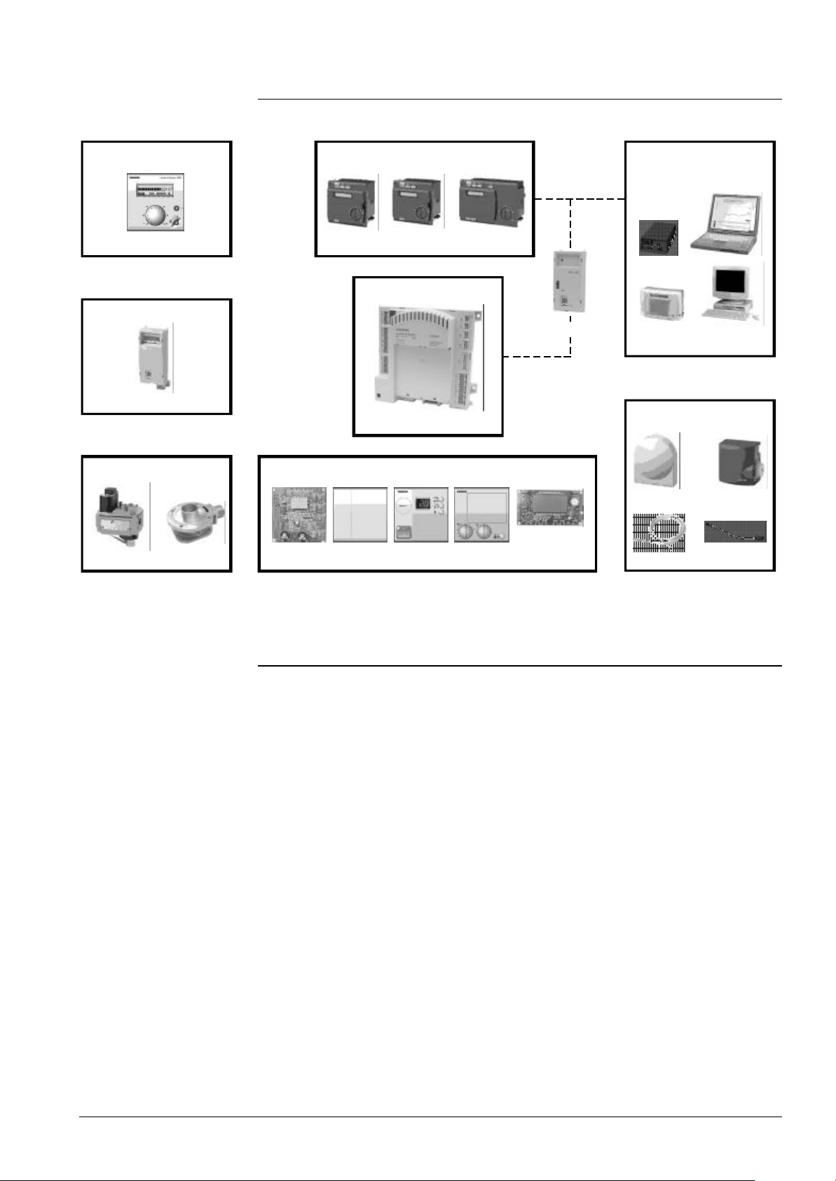
7494b02E/0802
Room units
QAA73...
Clip-in modules
AGU2.5xx
Gas valves / Mixer
AGU3.6...
Controllers
RVA46... RVA47... RVA...
BMU
OCI420...
LMU...
HMI
AGU2.350 AGU2.361 AGU2.362AGU2.303 AGU2.310
Service remote
management
ACS6... / OCI6...
Temp. sensors
QAC34...
QAZ36...
QAL36...VDU...
QAD36...
BMU
Controller
Service tool
The following units and accessories are designed for use with the ALBATROS range:
Type of unit Description Documentation no.
LMU54... BMU (without housing, without combustion optimization) CC1P7494
LMU64... BMU (with housing, without combustion optimization) CC1P7494
1)
1)
REA02... Room thermostat (RAA20) CE1N3002
REA11... Room temperature controller CE1P2274
RVA46... Heating controller CE1P2372
RVA47... Cascade controller for modulating gas-fired CE1P2379
heating boilers
RVA63... Heating circuit controller CE1P2373
RVA65... Heat energy manager CE1P2392
RVA66... Heating circuit or primary controller with DHW control CE1P2378
2)
2)
2)
OCI490A109 PC interface for ACS42X... -ACS420 Software for OCI490A109
ACS421 Final production test software
Remote supervision
ACS... Operating software CE1B2530
OCI6... Central communication unit CE1N2530 / 2531
15/171
Siemens Building Technologies Basic Documentation LMU54... / LMU64... CC1P7494en
HVAC Products 2 Product range overview 07.11.2002
2)
2)
Page 16

Room units
QAA73... RU for boiler control with OpenTherm interface CE1P2284
QAA53... RU for boiler control with OpenTherm interface CE1Q2282
Clip-in modules
Gas valve
Sensor
AGU2.500A109 Clip-in for additional heating circuit
AGU2.500A209 Clip-in for additional heating circuit (printed circuit board version)
AGU2.511A109 Clip-in function module, voltage relay
AGU2.513A109 Clip-in function module, current relay
AGU2.514A109 Clip-in function module, sensor relay
AGU2.515A109 Clip-in function module, digital input relay
OCI420A109 Clip-in for communication LPB interface
OCI420A209 Clip-in for communication LPB interface (printed circuit board version)
VDUxxx Compact gas control loop with pneumatic fuel / air CC1N7662
ratio control
AGU3.6... Gas / air mixing device (pressure side) --
QAC34/101 Outside sensor NTC 1kΩ CE1Q1811
QAD36/101 Strap-on temperature sensor NTC 10 kΩ -QAK36... Screwed immersion temperature sensor NTC 10 kΩ --
QAL36.225 Universal temperature sensor NTC 10 kΩ CE1Q1842
QAZ36.522/109 Cable temperature sensor NTC 10 kΩ, cable length 2 m CE1Q1843
QAZ36.526/109 Cable temperature sensor NTC 10 kΩ, cable length 6 m CE1Q1843
2)
2)
Operating section
Cable
AQL21.30 Holding spring for QAL36.225, 30 mm -AQL21.42 Holding spring for QAL36.225, 42 mm --
AGU2.350A109 Dummy cover, housing for flush panel mounting,
degree of protection IPx4D
AGU2.361A109 Operating section for boiler, housing for flush panel mounting,
degree of protection IPx4D
AGU2.362A109 Operating section for heating circuit, housing for flush panel mounting,
degree of protection IPx4D
AGU2.303B109 Operating section, type of printed circuit board
AGU2.310A109 Operating unit with LCD (printed circuit board version)
AGU2.100A109 Connecting cable LMU... Ö AGU2.303 / AGU2.361 / AGU2.310
AGU2.101A109 Connecting cable AGU2.361 Ö AGU2.362
AGU2.102A109 Connecting cable AGU2.361 Ö control panel mounting QAA73...
AGU2.103A109 Connecting cable service interface AGU2.361 Ö QAA73...
1) 2)
1) 2)
1) 2)
1) 2)
AGU2.104A109 Connecting cable LMU... Ö Clip-in module AGU2.500 / OCI420
1)
1)
1)
1)
1)
2)
1)
Refer to Operating Instructions CC1B7494
2)
On request
16/171
Siemens Building Technologies Basic Documentation LMU54... / LMU64... CC1P7494en
HVAC Products 2 Product range overview 07.11.2002
Page 17

3 Functions
3.1 Burner control
Program selection
EEPROM
Forced intermittent
operation
Parameterization enables certain parts of the burner control program to be changed,
thus permitting a number of different burner control sequences.
The burner control sequences are distinguished by their capacity ranges in which the
boilers shall operate.
In accordance with the standards, there are 3 different capacity ranges:
• < 70 kW
• 70...120 kW
• > 120 kW
For all capacity ranges, there are additional parameterization choices available,
enabling the burner control’s sequence and times to be matched to specific
requirements.
The EEPROM of the LMU... is used to store the burner control’s program sequence and
lockout positions.
Also, control parameters and other setting values are filed in EEPROM.
Forced intermittent operation ensures that the burner control initiates shutdown after no
more than 24 hours of continuous operation.
This enables the burner control to perform the internal self-tests included in the startup
and shutdown sequence.
Burner control program
The burner control’s program ensures orderly operation of the unit including startup and
shutdown as well as flame supervision.
The sequence can be altered by changing certain parameters.
If there are deviations from the defined sequence, or in the case of a reset, the program
initiates safety shutdown (home run) and then - depending on the setting made lockout, restart or start prevention.
The program sequence is controlled in accordance with the program’s phases. The
individual phases are grouped and include startup, operation, shutdown and home run.
After a reset (power on), the burner starts its home run. Depending on the available
(parameterized) input / output signals or program times (e.g. prepurging), the individual
program phases will be either executed or skipped.
The burner control’s program is designed for intermittent operation. To verify orderly
functioning (detection of faults), a complete program cycle is required.
In the «Standby» position, the burner control is ready to operate and waits for a heat
demand signal from the controller, or it demands start prevention (no release).
The burner control maintains the «Operation» position until no more heat is demanded
by the controller - but for no more than 24 hours. On completion of that period of time,
the burner control will automatically enforce intermittent operation.
17/171
Siemens Building Technologies Basic Documentation LMU54... / LMU64... CC1P7494en
HVAC Products 3 Functions 07.11.2002
Page 18
Sequence diagram
Capacity range < 70 kW
HMI
display:
Phase
Heat demand
Flame
Ignition
BV
LP (2)
LP (3)
LP (4)
NoG_Max
N_Vor
-N_Vor_Delta
+N_VL_Delta
N_VL
+N_ZL_Delta
N_ZL
-N_ZL_Delta
N_TL
-N_TL_Delta
NoG_Null
7494f01e/0801
22 0 1 2 3 654
PH_TNB
Home run
TLOTNB
PH_TLO PH_TNN
Standby
TNN tsa1 tsa2
PH_
STANDBY
PH_
STARTVER
PH_
STANDBY
THL1
PH_
THL1_1
dependent on
10 Hz
11 Bw
12 Hz+Bw
tsa
Operation
tv TBRE TW1 TW2 tvz tsa1 tsa2 tn
PH_TV PH_TBRE PH_TW1 PH_TW2 PH_TVZ
PH_
TSA1_1
PH_
THL2
PH_
TSA2_1
PH_
Z
THL2
PH_
ti
MODULATION
PH_
THL2
PH_
THL2
PH_
THL2_1
PH_TI
PH_
Z
THL2
PH_
THL2
ZZ
ZZ
parameter
setting
dependent on
parameter
setting
dependent on
20 2 4 7 21 99
tsa
PH_TN_1
THL1 (TW1)
PH_
PH_TW1
THL1_2
PH_
TSA1_2
PH_
THL2
Z Z
PH_
THL2
PH_
TSA2_2
PH_
TSA1_2
THL2 tn
PH_
PH_TN_2
THL2_2
Z
Z
ZZ
parameter
setting
ZZZZ
dependent on
parameter
setting
dependent on
parameter
setting
dependent on
parameter
setting
ZZZZ
PH_
STOER
Capacity range 70...120 kW
HMI
display:
Phase
Heat demand
Flame
Ignition
BV
LP (2)
LP (3)
LP (4)
NoG_Max
N_Vor
-N_Vor_Delta
+N_VL_Delta
N_VL
+N_ZL_Delta
N_ZL
-N_ZL_Delta
N_TL
-N_TL_Delta
NoG_Null
7494f02e/0201
PH_TNB
22
Home run
TLOTNB
PH_TLO PH_TNN
0 1
Standby
TNN tsa1 tsa2
PH_
STANDBY
PH_
STARTVER
PH_
STANDBY
3
2
tv TBRE
THL1
PH_
PH_TV PH_TBRE PH_TW1 PH_TW2 PH_TVZ
THL1_1
TW1
Z
R
dependent on
parameter
setting
10 Hz
11 Bw
654
12 Hz+Bw
tsa
Operation
TW2 tvz tsa1 tsa2 tn
PH_
TSA1_1
PH_
THL2
Z
PH_
TSA2_1
PH_
THL2
ti
PH_TI
PH_
THL2
Z
Z
PH_
PH_
THL2
THL2
R
PH_
MODULATION
PH_
THL2
20 2 4 7 21 99
PH_
PH_TN_1
THL2_1
Z
R
ZZ
RR
dependent on
parameter
setting
ZZ
ZZ
R
ZZ
RR
dependent on
parameter
setting
ZZ
THL1 (TW1)
PH_
PH_TW1
THL1_2
dependent on
parameter
setting
tsa
PH_
TSA1_2
PH_
THL2
Z Z
TSA2_2
PH_
THL2
PH_
TSA1_2
PH_
THL2_2
PH_TN_2
PH_
STOER
THL2 tn
PH_
Z
Z
ZZ
R
dependent on
parameter
setting
ZZ
dependent on
parameter
setting
ZZ
R
Z
RR
Logic on
Logic off
On deviation
transition to home run
Deviation leads to lockout
On deviation transition to
specified or following
phase
Control
Permitted range
Prohibited range
-> Home run
Prohibited range
-> Lockout
Control signal
Ideal signal
Transition criterion
Triggering forced prepurging
Z
Repetition can be parameterized,
R
then lockout
18/171
Siemens Building Technologies Basic Documentation LMU54... / LMU64... CC1P7494en
HVAC Products 3 Functions 07.11.2002
Page 19
Repetition can be parameterized,
Sequence diagram
Capacity range > 120 kW
HMI
display:
Phase
Heat demand
Flame
Ignition
BV
LP (2)
LP (3)
LP (4)
NoG_Max
N_Vor
-N_Vor_Delta
+N_VL_Delta
N_VL
+N_ZL_Delta
N_ZL
-N_ZL_Delta
N_TL
-N_TL_Delta
NoG_Null
7494f03e/0201
PH_TNB
Logic on
Logic off
On deviation
transition to home run
PH_
THL2
PH_
TSA2_1
ZZ
Z
10 Hz
11 Bw
12 Hz+Bw
Operation
PH_
ti
MODU-
PH_TI
LATION
PH_
THL2
20 2 4 7 21 99
PH_
THL2
PH_
THL2_1
dependent on
parameter
setting
PH_TN_1
ZZ
THL1 (TW1)
PH_
THL1_2
dependent on
parameter
setting
Permitted range
Prohibited range
-> Home run
Prohibited range
-> Lockout
22
Home run
TLOTNB
PH_TLO PH_TNN
0 1
Standby
TNN tsa1 tsa2
PH_
PH_
STANDBY
STARTVER
PH_
STANDBY
3
2
tv TBRE
THL1
PH_
PH_TV PH_TBRE PH_TW1 PH_TW2 PH_TVZ
THL1_1
dependent on
parameter
setting
TW1
654
tsa
TW2 tvz tsa1 tsa2 tn
PH_
TSA1_1
PH_
Z
THL2
dependent on
parameter
setting
Deviation leads to lockout
On deviation transition to
specified or following
phase
Control
PH_TW1
tsa
PH_
TSA1_2
PH_
Z Z
THL2
dependent on
parameter
setting
Z
R
THL2 tn
PH_
PH_
TSA2_2
THL2_2
PH_
THL2
PH_
TSA1_2
ZZ
dependent on
parameter
setting
Control signal
Ideal signal
Transition criterion
Triggering forced prepurging
then lockout
PH_TN_2
PH_
STOER
Z
Z
ZZ
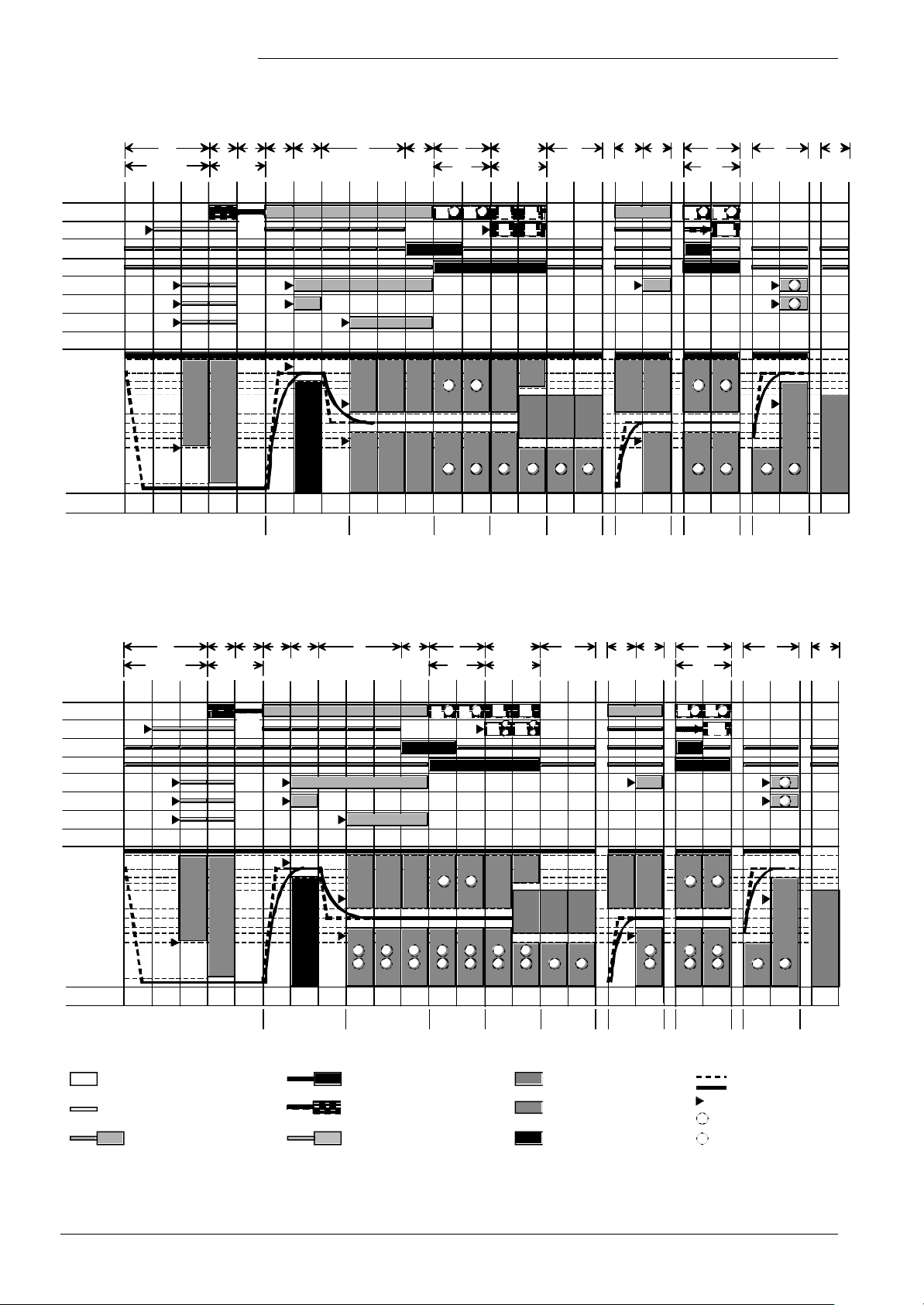
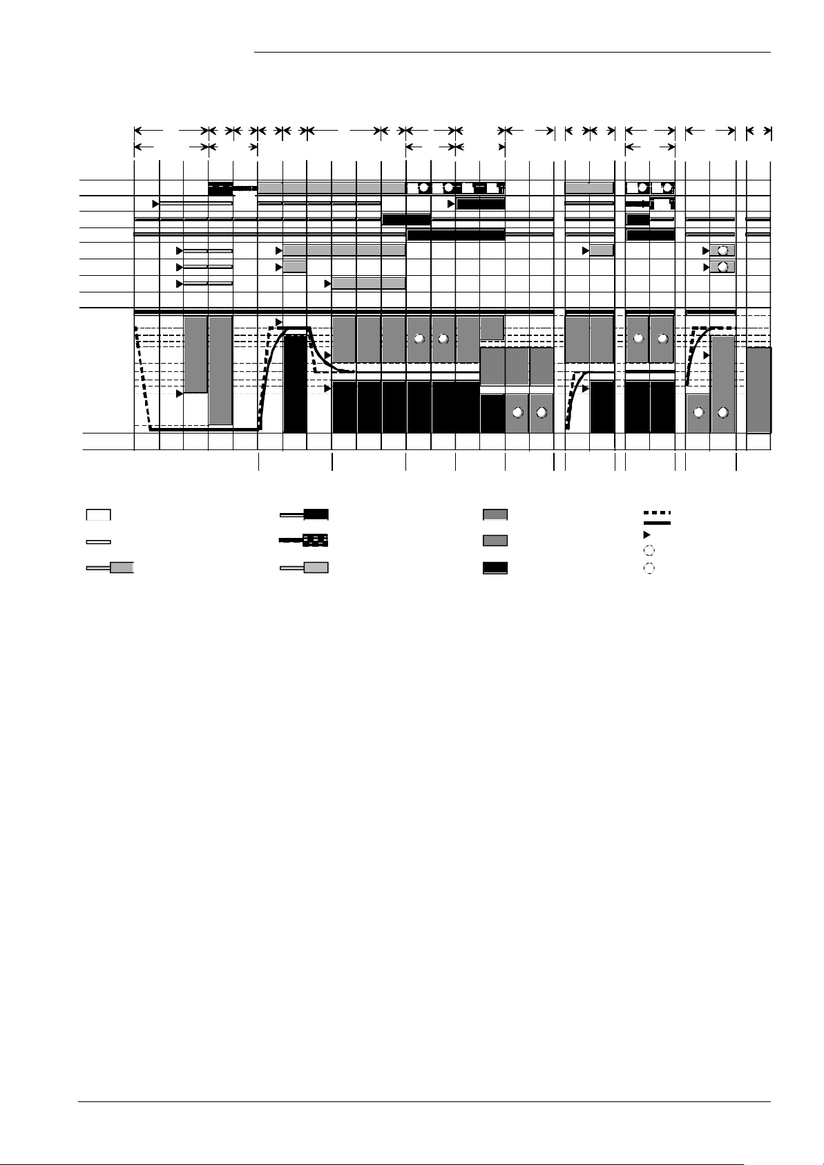
Description of sequence
diagrams
The burner control’s program is subdivided into different phases. Each phase is
identified by a certain output and input configuration of the burner control.
For the precise sequence of signals, refer to the sequence diagrams.
Signal sequences not shown in the sequence diagrams are summarized under «Special
cases».
The times given in the sequence diagrams are distinguished as follows:
UPPERCASE LETTERS (e.g. «THL1») constants stored in ROM
Lowercase letters (e.g. «tsa») parameters stored in EEPROM
With regard to the speed feedback signal, the following nominal levels are used:
N_Vor, N_VL, N_ZL, N_TL
Prepurging Nominal load
1)
Previously «Full load» (VL)
1)
Ignition load Partial load
Siemens Building Technologies Basic Documentation LMU54... / LMU64... CC1P7494en
HVAC Products 3 Functions 07.11.2002
19/171
Page 20
According to the sequence diagram, there is a permitted tolerance band with an upper
and a lower limit for each level (e.g. «N_ZL»), which is defined via parameter
«N_XX_Delta».
The relevant sequence phases (refer to the sequence diagrams) are queried for these
limits.
Example: Ignition load upper limit = «N_ZL» + «N_ZL_Delta»
lower limit = «N_ZL» - «N_ZL_Delta»
These limit values are complemented by «NoG_Null» and «NoG_Max» (refer to the
sequence diagrams).
«NoG_Max» is the maximum speed that must never be reached. «NoG_Null» is the low
speed that must be crossed when changing to standby.
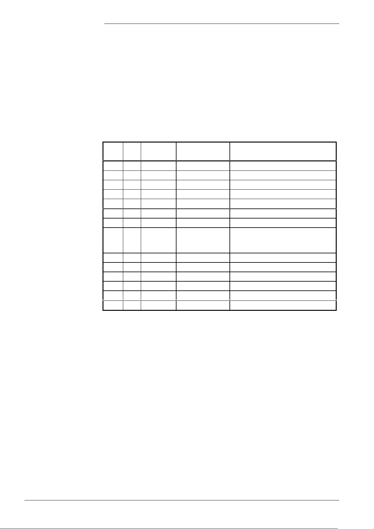
Sequence times
Time
Min.
(s)
TNB 0.2 21.0 Lockout position Afterburn time
TLO 0.2 51.0 Lockout position Open LP
TNN 0.2 51.0 Lockout position Down to speed = 0
THL1 0.2 51.0 Lockout position First fan runup time
THL2 0.2 51.0 Lockout position Second fan runup time
tv 0 51.0 Switching Prepurging
TBRE 0.2 51.0 Lockout position Brake time until ignition load is reached
TW1 0.2 51.0 Lockout position
tvz 0.2 5.0 Switching Preignition time
TSA 1.8 9.8
tsa1 0.2 9.6
tsa2 0.2 TSA-tsa1
ti 0.2 10 Switching Interval operation
tn 0 51.0 Switching Postpurging
1)
Lockout position or start repetition, depending on the flame signal and the parameter;
various parameterization choices (refer to relevant description)
2)
With parameterization with abortion of safety time in the case of flame detection, the times
of «tsa1» and «tsa2» are derived from the time of establishment of flame. It should be
noted, however, that «TSA» can never be exceeded
Max.
(s)
Response
Description
at end of
Waiting for internal sequence, speed
readjustment and optimization of
combustion
1)
2)
1)
2)
1)
Ignition safety time
Ignition safety time with ignition
Ignition safety time without ignition
The following phases (with associated times in parentheses) are relevant with one
startup / shutdown cycle:
Standby
• PH_STANDBY (unlimited): Burner control waits for a heat demand signal from the
controller
• PH_STARTVER: No external or internal release, relevant diagnostic code is delivered
Startup
The change from «Standby» to «Operation» is the startup triggered by a heat demand
signal from the controller.
If startup takes place with prepurging, startup will commence with the «PH_THL1_1»
phase; if no prepurging is used, with the «PH_THL1_2» phase.
20/171
Siemens Building Technologies Basic Documentation LMU54... / LMU64... CC1P7494en
HVAC Products 3 Functions 07.11.2002
Page 21

• PH_THL1_1 (THL1): Maximum fan runup time to prepurging level. With «tv» > 0 or in
case of demanded forced prepurging
• PH_THL1_2 (THL1): Maximum fan runup time to ignition level. With «tv» = 0 and no
demanded forced prepurging
• PH_TV (tv): Prepurging phase
• PH_TBRE (TBRE): Maximum period of time for reaching the ignition level after
prepurging (reaching the speed band for the ignition load)
• PH_TW1 (TW1): Maximum waiting time until the following functions are performed:
− Internal safety tests: These tests are started the moment the startup phase
commences and already run in the background during the preceding phases
− Combustion optimization: Optimization of combustion deactivated or stepper motor
in start position
− Speed readjustment: Checkback signal delivered when the required speed for the
ignition load is reached for the first time
• PH_TVZ (tvz): Preignition time (can be parameterized, but minimum is 0.2 seconds)
• PH_TSA1_1; PH_TSA2_1; PH_TSA1_2; PH_TSA2_2; (TSA): Ignition safety time. If,
on completion of this period of time, there is no flame (also after several reignition
attempts), the burner control will initiate lockout or make a restart, depending on the
parameter settings made.
With parameterization with abortion of the safety time in the case of flame detection,
«TSA» can be shortened via flame establishment (refer to «PH_TSA1_2»,
«PH_TSA2_2»).
Parameterization choice 1:
• PH_TSA1_1 (tsa1, max. TSA): First part of the safety time with ignition switched on.
The fuel valve is open
• PH_TSA2_1 (TSA - tsa1, max. TSA): Second part of the safety time with ignition
switched off. The fuel valve is open
Parameterization choice 2:
• PH_TSA1_2 (max. TSA): First part of the safety time with ignition switched on.
Once a flame signal is detected, the change to the «PH_TSA2_2» phase (switching
ignition off) takes place. If there is no establishment of flame, the burner control stays
in the «PH_TSA1_2» phase until the end of «TSA» is reached
• PH_TSA2_2 (0.2 seconds, can be run through several times during «TSA»):
Second part of the safety time with ignition switched off. The fuel valve is open. 0.2
seconds after the change to the «PH_TSA2_2» phase, the flame signal is checked. If,
in that case, the flame has been lost, an immediate reignition attempt is made by
returning to the «PH_TSA1_2» phase.
This procedure can repeat itself until the end of «TSA» is reached.
If the flame is still present, the change to the «PH_TI» phase takes place.
Operation:
Start of the operating position is the «PH_TI» phase. If interval «ti» is not required, it
cannot be parameterized to 0 but only to a minimum of 0.2 seconds.
• PH_TI; (ti), interval required for stabilization of the flame
• PH_MODULATION; (unlimited), controller operation. In this phase, the controller
result is output
21/171
Siemens Building Technologies Basic Documentation LMU54... / LMU64... CC1P7494en
HVAC Products 3 Functions 07.11.2002
Page 22

Shutdown
The change from the operating position to «Standby» is made when there is no more
demand for heat and is divided into «Shutdown» and «Home run».
«Shutdown» consists of postpurging, which can be deactivated.
With postpurging, there is a choice of 2 operating modes the difference being the way
the fan is controlled.
Parameterization choice 1:
• PH_THL2_1 (0.2 s): Change during postpurging, to the level of the last operating
command
• PH_TN1 (tn): Postpurging to the level of the last operating command
Parameterization choice 2:
• PH_THL2_2 (THL2): Change during postpurging, to the level of prepurging
• PH_TN2 (tn): Postpurging to the level of prepurging
Home run
Special cases (deviations)
The home run is used to bring about the change to the «Standby» position.
Normally, the home run is made on completion of «Shutdown».
After extraordinary events (refer to the sequence diagram), or in the case of a reset, the
home run brings the unit back to its basic position («Standby»).
In the case of a new demand for heat, the home run triggers a faster startup sequence.
This is accomplished by a shorter «TNN» followed by a direct change from the
«PH_TNN» phase to the «PH_THL1_1/2» phase. This means that the «Standby» state
will be skipped.
• PH_TNB (TNB): Permitted afterburn time
• PH_TLO (TLO): Permitted period of time with «LP» closed (if present) or speed >
«N_TL-N_TL_Delta»
• PH_TNN (TNN): Permitted period of time at speed > «NoG_Null»
• Forced prepurging: In the case of a reset after lockout and after power ON, forced
prepurging with the «LmodVOr» parameter is initiated, which takes place in the
«PH_TV» phase and which lasts 21 seconds, or «tv», if «tv» > 21 seconds.
The deviations marked with «Z» in the sequence diagram cause the burner control to
perform forced prepurging in the next startup phase.
• Repetition at the end of «TSA»: In the event no flame is established at the end of
«TSA», there is a choice of lockout or repetition can be triggered by changing to the
home run. The number of repetitions is limited and can be selected via the
«RepZaehler» parameter.
However, the general conditions of the different adjustable capacity ranges must be
observed (refer to the table further below).
• In the event of loss of flame during operation, the burner control initiates lockout or
changes to home run with restart, depending on the capacity range (refer to the table
further below)
• Prepurging: Can be deactivated by using the setting 0 seconds. In that case - as
shown on the sequence diagram - a change from the «PH_THL1_1» phase to the
«PH_TW1» phase will take place
• Preignition time: If parameter «tvz» is set to 0 (no ignition prior to «TSA»), the
«PH_TVZ» phase takes no more than 0.2 seconds (minimum time)
• Forced intermittent operation: After 24 hours of continuous operation at the latest,
forced intermittent operation is triggered, which ensures a regular shutdown to the
«PH_STANDBY» phase.
The timer for forced intermittent operation is reset in the «PH_STANDBY» phase.
Quick startup with forced intermittent operation is not possible.
22/171
Siemens Building Technologies Basic Documentation LMU54... / LMU64... CC1P7494en
HVAC Products 3 Functions 07.11.2002
Page 23
• Safety time (TSA): As described above, the behavior of the burner control in the 2
1 SW run
different modes can be parameterized: Abortion of the safety time with flame
detection, and evaluation of the flame at the end of the safety time.
It must be noted that in the case of single-electrode operation, it is always «Evaluation of
the flame at the end of the safety time» that must be parameterized.
• Postpurging: Can be parameterized in 2 different ways, namely as postpurging on
the prepurging level, or as postpurging with the control used last. The duration of
postpurging is adjusted via «tn» (also see above)
• Start prevention: Certain internal or external events can trigger start prevention. In
that case, the burner control changes to the «PH_STARTVER» phase. The reason for
start prevention is given via the diagnostic code
The reason can be one of the following (examples):
− Open-circuit or short-circuit of flame detector
− No «GP» signal (depending on the parameterization)
− Open «LP» input (depending on the parameterization)
− Temperature limiter has cut out
Some of the functions that give rise to start prevention can be deactivated via
parameterization.
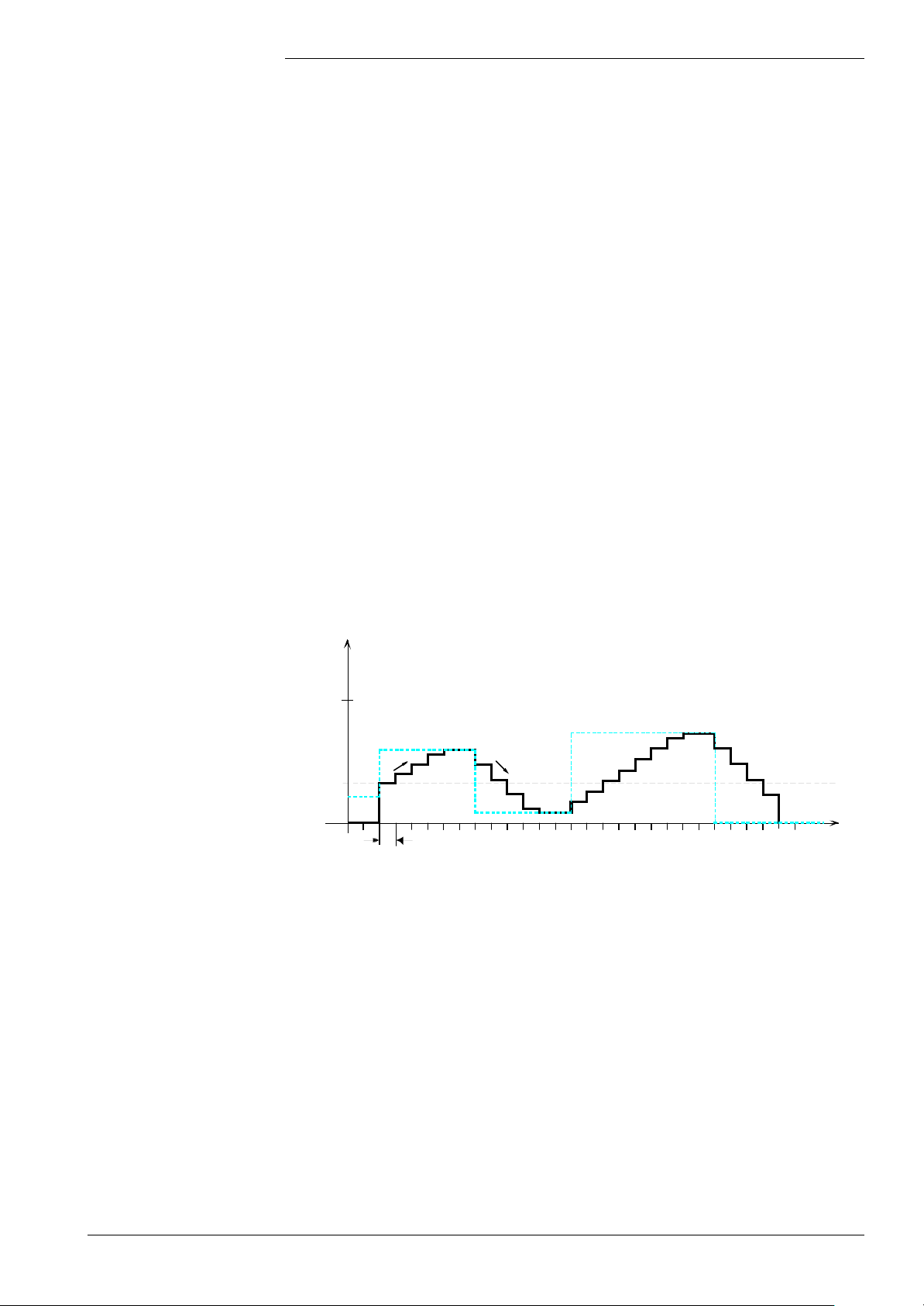
• Ramps: Fan control can be limited by a ramp. To do this, a number of
parameterization choices are available.
The rate of signal change towards a higher or lower speed is limited via parameter
(VmLauf, VmLaufBetr, VmLab, VmLabBetr).
In all phases - with the exception of «PH_MODULATION» - parameters «VmLauf»
and «VmLab» apply to the rate of change of fan control up or down.
PWM
100 %
Setpoint
Ramp (DOWN)
Threshold
value
Control value following the setpoint while considering the threshold value and the ramps
Ramp (UP)
7494d21E
In the «PH_MODULATION» phase, the increase of fan control is limited by the smaller
of the 2 parameters «VmLaufBetr» and «VmLauf».
The decrease is limited by the smaller of the 2 parameters «VmLab» and «VmLabBetr».
Also, when controlling the fan, a threshold value is to be considered. It is predefined by
the «LmodStart» parameter.
As long as the setpoint is lower than the threshold value, the fan will not be controlled. It is
controlled only - using the threshold value - when the setpoint is at least equal to the
threshold value.
23/171
Siemens Building Technologies Basic Documentation LMU54... / LMU64... CC1P7494en
HVAC Products 3 Functions 07.11.2002
Page 24
If the setpoint lies above the threshold value, starting from the threshold value, the
control value will approach the setpoint in accordance with the maximum slope (ramp)
defined by parameters «VmLauf» and «VmLaufBetr».
If the setpoint lies below the current control value, the control value will approach the
setpoint in accordance with the ramp (VmLab, VmLabBetr). This also applies in the case
the setpoint is lower than the threshold value.
If the setpoint equals zero, which means that the fan shall be switched off, first the
control value will be reduced in accordance with the ramp until it is smaller than or equal
to the threshold value. Only then will the control value be reduced to zero.
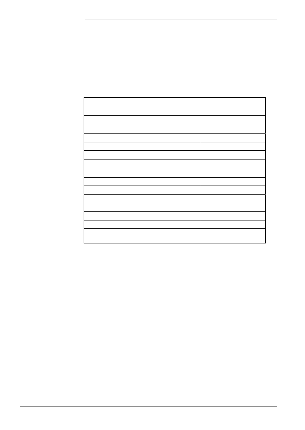
LMU... plausibility checks
of the speed parameters
Fault Display of fault on the
PC tool
Check PWM control values of the fan for plausibility in relation to other parameters:
LmodZL > LmodVL 218
LmodTL > LmodZL 219
LmodNull > LmodTL 220
Check speed parameters of the fan for plausibility in relation to other parameters:
N_TL > N_VL 221
N_VOr > NoG_Max 222
N_VL + N_VL_Delta > NoG_Max 223
N_ZL + N_ZL_Delta > N_VL + N_VL_Delta 224
N_VOr - N_VOr_Delta < NoG_Null 225
N_ZL - N_ZL_Delta < N_TL - N_TL_Delta 226
N_TL - N_TL_Delta < NoG_Null 227
N_Nachstell_Delta ≥ N_ZL_Delta
or N_Nachstell_Delta ≥ N_Vor_Delta
503
Parameterization of
speed feedback signal
24/171
The fan’s speed feedback signal can be parameterized.
Parameter: Fan pulses (in «FaEinstellFlags3»)
Available choices : 2, 3 or 4 pulses per revolution
Siemens Building Technologies Basic Documentation LMU54... / LMU64... CC1P7494en
HVAC Products 3 Functions 07.11.2002
Page 25
Fan parameters
accessible via QAA
Under certain conditions, the fan parameters for ignition load, partial load and full load
can also be set via the QAA73... (parameter «FaEinstellFlags3»).
Since these fan parameters are safety-related and – as a general rule – safety-related
values cannot be readjusted via the QAA73..., following applies:
• The relevant parameters will be copied and the new parameters filed in the nonsafety-related range
• Changeover between the 2 parameter groups can be parameterized via a safetyrelated flag (FaEinstellFlags3)
Changeover to the QAA fan parameters is only permitted under certain preconditions:
1. Capacity range < 70 kW.
2. Changeover only possible on the OEM level or higher.
For the new parameters, the usual fan parameter checks are made (same as with the
previous parameter group).
Listing of both parameter groups:
Parameters on QAA Safety-related parameters
LmodZL_QAA LmodZL
LmodTL_QAA LmodTL
LmodVL_QAA LmodVL
Note
N_ZL_QAA N_ZL
N_TL_QAA N_TL
N_VL_QAA N_VL
When setting these parameters, the following general conditions must be observed:
QAA parameters : CRC-protected parameter:
LmodZL_QAA ≤ LmodZL
LmodVL_QAA ≤ LmodVL
LmodTL_QAA ≥ LmodTL
N_ZL_QAA ≤ N_ZL
N_VL_QAA ≤ N_VL
N_TL_QAA ≥ N_TL
When, in the following, reference is made to one of the safety-related parameters, it is
also possible that the corresponding QAA parameter is meant (depending on the
parameterization).
25/171
Siemens Building Technologies Basic Documentation LMU54... / LMU64... CC1P7494en
HVAC Products 3 Functions 07.11.2002
Page 26

The different capacity
ranges
In compliance with the standards, a differentiation must be made with regard to the
responses in the sequence diagram for the different boiler capacity ranges.
Parameter «FaProgFlags1» can be used to select the 3 following ranges:
FaProgFlags1 (Bit7) FaProgFlags1 (Bit6) Capacity range
0 0 < 70 kW
0 1 70...120 kW
1 0 > 120 kW
From these 3 capacity ranges, the following differences emerge:
Capacity range
Subject < 70 kW 70 - 120 kW > 120 kW
Air supply failure during
prepurging, ignition or in
operation:
1)
Failure during
establishment of flame:
2)
Response:
Home run; during the safety time and
in operation also forced prepurging.
During prepurging, immediate lockout.
Response:
Shutdown on first occurrence, restart
permitted (number of restarts can be
parameterized). Then lockout; also
forced prepurging.
Repetition counter is reset in phase
Response:
Home run on first occurrence, one restart permitted
(number 0 / 1 can be parameterized). Then lockout;
also forced prepurging.
During prepurging, immediate lockout.
Repetition counter is reset in the «PH_TI » phase.
Response:
Shutdown on first occurrence, one restart permitted
(number 0 / 1 can be parameterized). Then lockout;
also forced prepurging.
Repetition counter is reset in the «PH_TI » phase.
Response:
Lockout
position
4)
Response:
Lockout
position
4)
«PH_TI ».
Loss of flame during
operation:
3)
Response:
Shutdown
Response:
Shutdown on first occurrence, one restart permitted
(number 0 / 1 can be parameterized). Then lockout;
also forced prepurging.
Repetition counter is reset in the «PH_TI » phase.
Response:
Lockout
position
4)
1)
With the LMU...: Failure of speed supervision or speed feedback signal below the valid
range.
Relevant phases: PH_TV, PH_TW1, PH_TW2, PH_TVZ, PH_TSA1_1, PH_TSA2_1,
PH_TSA1_2, PH_TSA2_2, PH_TI, PH_MODULATION
2)
With the LMU...: No flame at the end of the safety time. Relevant phases: PH_TSA1_1,
PH_TSA2_1, PH_TSA1_2, PH_TSA2_2
3)
With the LMU...: Loss of flame during phases «PH_TI» and «PH_MODULATION»
4)
Accomplished by parameterizing the specified value for the start repetitions to 0
26/171
Siemens Building Technologies Basic Documentation LMU54... / LMU64... CC1P7494en
HVAC Products 3 Functions 07.11.2002
Page 27
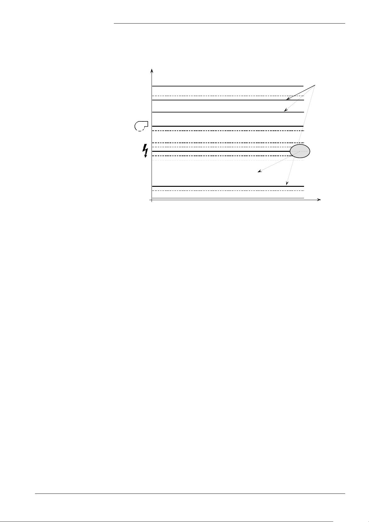
Setting the fan parameters
during startup and shutdown
Parameter LMU...
Speed
[min-1]
NoG_MAX
Signal
PWM [%]
To visualize the following description, also refer to the sequence diagram of the LMU…
and the following graph.
Speed limitation
KonfigRg5)
N_VL*
(N_VL_Delta)
N_VL_QAA*
NhzMax
N_Vor
(N_Vor_Delta)
(N_ZL_Delta)
N_Nachstell_Delta
N_ZL* LmodZL*
N_Nachstell_Delta
(N_ZL_Delta)
N_ZL_QAA*
N_TL*
(N_TL_Delta)
N_TL_QAA*
NoG_Null
* Depending on parameter «FaEinstellFlags3»
LmodVL*
LmodVL_QAA*
PhzMax
LmodVor
LmodZL_QAA*
LmodTL*
LmodTL_QAA*
LmodNull
Fan control and speed parameters
First, set the speed limits while speed readjustment is switched off.
For that purpose, set the fan control parameters («LmodZL», «LmodVor», etc.) to the
values required from the combustion point of view (with the medium flueway and at
mains voltage).
Then, also determine the associated fan speeds from the fan characteristic and
parameterize them accordingly («N_ZL», «N_Vor», etc.).
In a first approach, set the limit values for the permitted bands very wide
(«N_ZL_Delta», «N_Vor_Delta», etc.).
The values of fan control and fan speed can now be optimized.
MAX
MAX
MIN
Boiler
Boiler
Heating
OFF
Extra function «Speed readjustment»
(optional)
N_Nachstell Kon1
N_Nachstell_Lern
7494d31E
Speed limits
First, the speed readjustment should be set to the required or parameterized speed
readjustment.
When the optimization or setting is completed, proceed to the next step and determine
and set the speed limits.
For that purpose, use the PC tool and record the speed (Gebl_F_Drehz) in a startup and
shutdown cycle under the following boundary conditions:
1. With the minimum flueway and undervoltage (AC 195 V)
2. With the maximum flueway and overvoltage (AC 253 V)
Now, set the speed bands (speed limits about the selected speeds, that is, «N_ZLV +/N_ZL_Delta», etc.) such that in all possible worst cases, the measured speed lies within
the valid band (see above).
Faults outside these worst cases give rise to a violation of the speed limits and lead to
appropriate reactions (refer to sequence diagram).
27/171
Siemens Building Technologies Basic Documentation LMU54... / LMU64... CC1P7494en
HVAC Products 3 Functions 07.11.2002
Page 28

Speed readjustment
Speed readjustment is active during startup and shutdown (not during controller
operation where speed limitation can be activated).
The basic task of speed readjustment is to act on the fan control in such a way that the
resultant speed (after a certain settling time) will lie within an accepted speed band.
Hence, external effects (over- or undervoltage, minimum or maximum flueway, etc.) can
largely be offset.
The following parameters must be considered:
• N_NachstellKon1 (in «FaEinstellFlags2»)
This parameter is used to activate or deactivate the function during startup.
• N_NachstellKon2 (in «FaEinstellFlags2»)
This parameter is used to activate or deactivate the function during shutdown.
• N_Nachstell_lern (in «FaEinstellFlags2»)
This parameter is used to activate or deactivate the learning function of fan control.
• N_Nachstell_Delta
This parameter predefines the band (+/-) to which the speed will be readjusted (neutral
band).
• Nachstell_Zaehler
This parameter is used to define the time when ignition shall be started (depending on
the fan speed settling time à more or less overshoot on ignition permitted).
Description
Learning function
If the function is activated (N_NachstellKon1 + N_NachstellKon2), the fan output signal
will be readjusted in order to get the speed back into the predefined band (e.g. N_ZL +/N_Nachstell_Delta).
If speed readjustment is used, the actual speed will be readjusted to nearly the required
speed until ignition takes place.
Since with this readjustment, the fan speed requires a certain settling time, it is very
advisable to parameterize prepurging and ignition at the same level, so that the
prepurging time can be used for settling process.
If, for example, prepurging > ignition, a second settling process will take place, that is,
the deviation at the time of ignition will be greater.
In that case, the prepurging time should be changed and the level of prepurging and
ignition should be the same.
During startup, the fan output will be changed in order to readjust the resulting actual
speed.
To ensure that this practically fixed offset does not need to be readjusted on each
startup, the fan output signal will be acquired at the end of startup, and the value
learned will be used next time the burner is started up.
This means that the settling process will be accelerated.
The learning function can be deactivated with flag «N_Nachstell_lern» (in
«FaEinstellFlags2»).
28/171
Siemens Building Technologies Basic Documentation LMU54... / LMU64... CC1P7494en
HVAC Products 3 Functions 07.11.2002
Page 29

Reinitialization
In the following cases, a reinitialization will be made or the parameterized control values
learned:
• In the event of a fault in connection with the fan
• In the event of a reset
• After power ON
Tolerance of settling
process during startup
Especially in cases where the prepurge level deviates from the ignition level, the fan
speed needs a certain time to settle out just prior to ignition. Depending on the
application, this speed variation can give rise to more or less disturbance.
Parameter «Nachstell_Zaehler» can be used to adjust the permitted degree of fan
speed settling, or from when the change to ignition shall take place.
If a small value is parameterized (e.g. 1), ignition is effected immediately. The greater
the value, the less overshoot is permitted on ignition.
It should be noted that greater values extend the startup phase.
29/171
Siemens Building Technologies Basic Documentation LMU54... / LMU64... CC1P7494en
HVAC Products 3 Functions 07.11.2002
Page 30
3.2 Selection of the compensation variants
Legend
Different types of compensation are used for the heating and the DHW circuit, depending
on the types of plant components. On completion of a certain startup time, during which
the connected components are queried, the relevant compensation variant is selected.
If plant components are connected or removed during operation, the compensation variant
changes after the new plant state is identified.
Heating circuits
The plant components decisive for the compensation variant of heating circuits 1 and 2
or the following:
• The RU
• The outside sensor
• The HMI (none / cannot be parameterized / can be parameterized)
External heat demand signals (via the RVA...) are received directly and are not included
in the following table.
Without HMI
RU
QAA53 /
QAA73
Not present – – Not present
Not present – – Present TvSollWf1 TvSollWf2
Present No No Not present
Present No No Present TvSollWf1 TvSollWf2
Present Yes No Not present Tset / Tset2
Present Yes No Present Tset / Tset2 TvSollWf2
Present Yes Yes Not present Tset / Tset2 Tset / Tset2
Present Yes Yes Present Tset / Tset2 Tset / Tset2
Present No Yes Not present
Present No Yes Present TvSollWf1 Tset / Tset2
RU for Hk1
active
RU for Hk2
active
Outside
sensor
Setpoint Hk1
TkSoll
TvSollWf1 at
TaGem = 0 °C
TvSollWf1 at
TaGem = 0 °C
TvSollWf1 at
TaGem = 0 °C
Setpoint Hk2
TvSoll
TvSollWf2 at
TaGem = 0 °C
TvSollWf2 at
TaGem = 0 °C
TvSollWf2 at
TaGem = 0 °C
Tset / Tset2
Compensation
variant heating
circuit 1
Emergency
operation
Weather compensation LMU
Emergency
operation
Weather compensation LMU
Room compensation RU
Weather compensation RU
Room compensation RU
Weather compensation RU
Emergency
operation
Weather compensation LMU
Compensation
variant heating
circuit 2
Emergency
operation
Weather compensation LMU
Emergency
operation
Weather compensation LMU
Emergency
operation
Weather compensation LMU
Room compensation RU
Weather compensation RU
Room compensation RU
Weather compensation RU
TvSollWf1 Flow temperature setpoint resulting from weather compensation for heating circuit 1
TvSollWf2 Flow temperature setpoint resulting from weather compensation for heating circuit 2
TsRaumMmi Room temperature setpoint of HMI
TSet Flow temperature setpoint of RU for heating circuit 1
Tset2 Flow temperature setpoint of RU for heating circuit 2
TrSet Room temperature setpoint of RU for heating circuit 1
RT / SU Room thermostat / time switch
SU program Hz1 Time switch program on the AGU2.310 for heating circuit 1
RU1 / V Heat demand from RU for heating circuit 1/ heating circuit 2
– Will not be evaluated
30/171
Siemens Building Technologies Basic Documentation LMU54... / LMU64... CC1P7494en
HVAC Products 3 Functions 07.11.2002
Page 31
With HMI AGU2.362 /
AGU2.362, AGU2.303
RU
QAA53 /
RU for Hk1
active
RU for Hk2
active
Outside
sensor
Setpoint Hk1
TkSoll
Setpoint Hk2
TvSoll
QAA73
Not present – – Not present
Not present – – Present TvSollWf1 TvSollWf2
Present No No Not present
Present No No Present TvSollWf1 TvSollWf2
Present Yes No Not present Tset / Tset2
Present Yes No Present Tset / Tset2 TvSollWf2
Present Yes Yes Not present Tset / Tset2 Tset / Tset2
Present Yes Yes Present Tset / Tset2 Tset / Tset2
Present No Yes Not present
Present No Yes Present TvSollWf1 Tset / Tset2
TvSollMmi
(setting pot)
TvSollMmi
(setting pot)
TvSollMmi
(setting pot)
TvSollMmi
(setting pot)
TvSollMmi
(setting pot)
TvSollMmi
(setting pot)
Tset / Tset2
Compensation
variant heating
circuit 1
Fixed value
control
Weather compensation LMU
Fixed value
control
Weather compensation LMU
Room compensation RU
Weather compensation RU
Room compensation RU
Weather compensation RU
Fixed value
control
Weather compensation LMU
Compensation
variant heating
circuit 2
Fixed value
control
Weather compensation LMU
Fixed value
control
Weather compensation LMU
Fixed value
control
Weather compensation LMU
Room compensation RU
Weather compensation RU
Room compensation RU
Weather compensation RU
With HMI AGU2.310
RU
QAA53 /
QAA73
Not present – –
Not present – – Present TvSollWf1 TvSollWf2
Present No No
Present No No Present TvSollWf1 TvSollWf2
Present Yes No
Present Yes No Present Tset / Tset2 TvSollWf2
Present Yes Yes
Present Yes Yes Present Tset / Tset2 Tset / Tset2
Present No Yes
Present No Yes Present TvSollWf1 Tset / Tset2
RU for
Hk1
active
RU for
Hk2
active
Outside
sensor
Not
present
Not
present
Not
present
Not
present
Not
present
Setpoint Hk1
TkSoll
TvSollMmi acc. to
SU prog. HMI Hz1
TvSollMmi acc. to
SU prog. HMI Hz1
Tset / Tset2 TvSollMmi
Tset / Tset2 Tset / Tset2
TvSollMmi acc. to
SU prog. HMI Hz1
Setpoint Hk2
TvSoll
TvSollMmi
TvSollMmi
Tset / Tset2
Compensation
variant heating
circuit 1
Fixed value
control
Weather compensation LMU
Fixed value
control
Weather compensation LMU
Room compensation RU
Weather compensation RU
Room compensation RU
Weather compensation RU
Fixed value
control
Weather compensation LMU
Compensation
variant heating
circuit 2
Fixed value
control
Weather compensation LMU
Fixed value
control
Weather compensation LMU
Fixed value
control
Weather compensation LMU
Room compensation RU
Weather compensation RU
Room compensation RU
Weather compensation RU
31/171
Siemens Building Technologies Basic Documentation LMU54... / LMU64... CC1P7494en
HVAC Products 3 Functions 07.11.2002
Page 32
Room setpoint
Note
Without HMI
The room setpoint is obtained from the following tables:
HzA: Heating circuit of the LMU... (1 or 2) which is controlled by the main heating
circuit of the RU (RU1)
HzB: Heating circuit of the LMU... (1 or 2) which is controlled by the secondary heating
circuit of the RU (RU2)
Refer to «Configuration of the heating circuits».
Hz1 and Hz2 can also be simultaneously assigned to the RU1 or RU2 program.
Without the RU , HzA = Hz1 and HzB = Hz2
RU
QAA53 /
QAA73
Beliebig No – – Don’t care (TrSmin+TrSmax) / 2 (TrSmin+TrSmax) / 2
Present Yes No No
Present Yes No Yes
Present Yes Yes No
Present Yes Yes Yes
Room
setpoint RU
active
RU1 active
for heating
circuit
RU2 active
for heating
circuit
Outside
sensor
Don’t care
Don’t care
Don’t care
Don’t care
Room setpoint HzA Room setpoint HzB
(TrSmin+TrSmax) / 2 (TrSmin+TrSmax) / 2
(TrSmin+TrSmax) / 2 (TrSmin+TrSmax) / 2
TrSet (TrSmin+TrSmax) / 2
TrSet (TrSmin+TrSmax) / 2
With HMI AGU2.361 /
AGU2.362, AGU2.303
RU
QAA53 /
QAA73
Don’t care No – –
Don’t care No – – Present TrSollMmi TrSollMmi
Present Yes No No
Present Yes No Nein Present TrSollMmi TrSollMmi
Present Yes No Yes
Present Yes No Yes Present TrSollMmi (TrSmin+TrSmax) / 2
Present Yes Yes No
Present Yes Yes No Present TrSet TrSollMmi
Present Yes Yes Yes Don’t care TrSet (TrSmin+TrSmax) / 2
Room
setpoint RU
active
RU1 active
for heating
circuit
RU2 active
for heating
circuit
Outside
sensor
Not
present
Not
present
Not
present
Not
present
Room setpoint HzA Room setpoint HzB
(TrSmin+TrSmax) / 2 (TrSmin+TrSmax) / 2
(TrSmin+TrSmax) / 2 (TrSmin+TrSmax) / 2
(TrSmin+TrSmax) / 2 (TrSmin+TrSmax) / 2
TrSet (TrSmin+TrSmax) / 2
32/171
Siemens Building Technologies Basic Documentation LMU54... / LMU64... CC1P7494en
HVAC Products 3 Functions 07.11.2002
Page 33
With HMI AGU2.310
RU
QAA53 /
QAA73
Don’t care
Don’t care
Present Yes No No
Present Yes No No Present
Present Yes No Yes
Present Yes No Yes Present
Present Yes Yes No
Present Yes Yes No Present TrSet TrSollMmi
Present Yes Yes Yes Don’t care TrSet (TrSmin+TrSmax) / 2
Room
setpoint RU
active
No – –
No – – Present
RU1 active
for heating
circuit
RU2 active
for heating
circuit
Outside
sensor
Not
present
Not
present
Not
present
Not
present
Room setpoint HzA Room setpoint HzB
(TrSmin+TrSmax) / 2 (TrSmin+TrSmax) / 2
TrSollMmi, reduced acc. to
SU program Hz1
(TrSmin+TrSmax) / 2 (TrSmin+TrSmax) / 2
TrSollMmi, reduced acc. to
SU program Hz1
(TrSmin+TrSmax) / 2 (TrSmin+TrSmax) / 2
TrSollMmi, reduced acc. to
SU program Hz1
TrSet (TrSmin+TrSmax) / 2
TrSollMmi
TrSollMmi
(TrSmin+TrSmax) / 2
33/171
Siemens Building Technologies Basic Documentation LMU54... / LMU64... CC1P7494en
HVAC Products 3 Functions 07.11.2002
Page 34
Configuration of the
heating circuits
The RU is a multifunctional unit for 1 or 2 heating circuits. For that purpose, it has a
main heating circuit (heating circuit 1) and - only with the QAA73... - a secondary
heating circuit (heating circuit 2).
The choice which of the RU’s heating circuits acts on which of the LMU’s heating circuits
is made with the « KonfigHks» parameter. This parameter is conceived such that it
allows the RU’s influence on heating circuits 1 and 2 of the LMU... to be defined
separately.
For both heating circuits of the LMU..., the following choices exist:
• No RU influence (0)
• Controlled by the main heating circuit of the RU (1)
• Controlled by the secondary heating circuit of the RU (2)
When no RU is used, this parameter is of no importance.
Control of an LMU’s heating circuit by the RU presupposes that the controlling heating
circuit in the RU is not deactivated (the heating circuits of the RU can be deactivated by
changing the slope).
If, in the RU , the heating circuit selected for the control is deactivated, the action is the
same as with setting «No RU influence» using the «KonfigHks» parameter.
The following assignments can be made:
Parameter
KonfigHks
RU influence on
heating circuit 2
of the LMU6x
0 0 0
1 0 1
2 0 2
10 1 0
11 1 1
12 1 2
20 2 0
21 2 1
22 2 2
RU influence on
heating circuit 1
of the LMU6x
Impact
Both heating circuits of the LMU... are without RU
influence
Hz2 without RU influence, Hz1 is controlled by the
main heating circuit of the RU, if RU is present
Hz2 without RU influence, Hz1 is controlled by the
secondary heating circuit of the RU, if RU is present
Hz1 without RU influence, Hz2 is controlled by the
main heating circuit of the RU, if RU is present
Both heating circuits of the LMU mare controlled by
the main heating circuit of the RU, if RU is present
Hz1 is controlled by the secondary heating circuit of
the RU, Hz2 by the main heating circuit of the RU, if
RU is present
Hz1 without RU influence, Hz2 is controlled by the
secondary heating circuit of the RU, if RU is present
Hz1 is controlled by the main heating circuit of the
RU, Hz2 by the secondary heating circuit of the RU,
if RU is present
Hz1 and Hz2 are controlled by the secondary
heating circuit of the RU, if RU is present
34/171
Siemens Building Technologies Basic Documentation LMU54... / LMU64... CC1P7494en
HVAC Products 3 Functions 07.11.2002
Page 35
DHW circuit
Without HMI
The plant components decisive for the DHW circuit’s compensation variant are the
following:
• LPB clip-in OCI420...
• The RU
• The HMI
• DHW sensor 1
LPB clip-in DHW sensor 1
TbwIst1
Not present or
DHW locked
Not present or
DHW locked
Not present or
DHW locked
Present and DHW
released
Present and DHW
released
Present and DHW
released
1)
1)
1)
Not present Don’t care TbwSmin Locked Locked
Present Not present
Present Present TdhwSet RU-DHW RU-compensated
Not present Don’t care
Present Not present TbwSollRva RVA-DHW RVA-compensated
Present Present TbwSollRva RVA-DHW RVA-compensated
With HMI AGU2.361 /
AGU2.362, AGU2.303
LPB clip-in DHW sensor 1
TbwIst1
Not present or
DHW locked
Not present or
DHW locked
Not present or
DHW locked
Not present or
DHW locked
Present and DHW
released
Present and DHW
released
Present and DHW
released
1)
1)
1)
Not present Don’t care TbwSmin Locked Locked
Present Not present TbwSollMmi
Present Present TdhwSet
Present Present
Not present Don’t care
Present Not present TbwSollRva RVA-DHW RVA-compensated
Present Present TbwSollRva RVA-DHW RVA-compensated
RU
QAA73...
RU
QAA73...
DHW setpoint
TempAnfoVeBw
(TbwSmin+
TbwSmax) / 2
TbwSmin
(DHW heated by RVA)
DHW setpoint
TempAnfoVeBw
3)
TbwSollMmi
TbwSmin
(DHW heated by RVA)
3)
DHW demand Compensation
variant
DHW circuit
Continuously or via
time switch
LMU-internal DHW
heating locked
2)
Emergency operation
Locked
DHW demand Compensation
variant DHW circuit
Continuously or via
time switch
RU-DHW RU-compensated
RU-DHW
LMU-internal DHW
heating locked
2)
Fixed value control
RU- / HMIcompensated
Locked
35/171
Siemens Building Technologies Basic Documentation LMU54... / LMU64... CC1P7494en
HVAC Products 3 Functions 07.11.2002
Page 36
With HMI AGU2.310
If the DHW operating mode of the AGU2.310 is on standby, the compensation variant in
the DHW circuit is generally locked, with DHW setpoint «TbwSmin» and DHW demand
locked.
If the operating mode is not on standby, the following table applies:
LPB clip-in DHW sensor 1
TbwIst1
Not present or
DHW locked
Not present or
DHW locked
Not present or
DHW locked
Not present or
DHW locked
Present and DHW
released
Present and DHW
released
Present and DHW
released
1)
1)
1)
Legend
Not present Don’t care TbwSmin Locked Locked
Present Not present TbwSollMmi Always Fixed value control
Present Present
Present Present TbwSollMmi
Not present Don’t care
Present Not present TbwSollRva RVA-DHW RVA-compensated
Present Present TbwSollRva RVA-DHW RVA-compensated
TbwSmin Minimum DHW temperature setpoint
TbwSmax Maximum flow temperature setpoint
TbwSollMmi DHW temperature setpoint of the HMI
TbwSollRva DHW setpoint of the RVA...
TdhwSet DHW temperature setpoint of the RU
TempAnfoVeBw Resulting DHW temperature setpoint
RU-Bw DHW demand from the RU
RVA-Bw DHW demand from the RVA...
RU
QAA73...
DHW setpoint
TempAnfoVeBw
TdhwSet
TbwSmin
(DHW heated by RVA)
3)
3)
DHW demand Compensation
variant
DHW circuit
RU-DHW RU-compensated
RU-DHW
LMU-internal DHW
heating locked
RU- / HMIcompensated
Locked
36/171
1) The information «Present and DHW released» results from the following:
• LPB clip-in is contained in the user list of the internal bus
• The connected RVA... controller delivers a DHW setpoint
2) A time switch for the DHW demand must be released via prameterization
(KonfigRg1.Schaltuhr2Bw =1 and KonfigRg1.Schaltuhr2 =1).
It is to be connected to the RU input. This function cannot be used in connection with
a RU
3) Can be selected via parameterization «KonfigRg6.2»
Siemens Building Technologies Basic Documentation LMU54... / LMU64... CC1P7494en
HVAC Products 3 Functions 07.11.2002
Page 37
3.3 Acquisition of actual values
All actual values are read in via AD conversion. A description of the individual channels
is given below.
Assignment of
analog sensors
The LMU… has 6 analog read-in channels that can be configured in different ways.
Configura-
tion
1 TkIst TkRuec TbwIst1 Tabgas * TiAussen Ph2o
2 TkIst TkRuec TbwIst1 Tabgas * TbwIst2 Ph2o
3 TkIst TbwIst2 TbwIst1 Tabgas * TiAussen Ph2o
4 TkIst TkRuec TbwIst1 TbwIst2 * TiAussen Ph2o
Analog 1
(tested)
Analog 2
(tested)
Analog 3 Analog 4 Analog 5 Analog 6
* Variant (in parameterization and hardware version)
The selection of AD configuration is made via parameterization (KonfigRg3.0-4).
Each sensor can be checked for open-circuit or short-circuit.
With all sensors that activate functions automatically, open-circuit error messages
cannot be generated.
In the event of an open-circuit, it is therefore possible to select whether the sensor shall
generate an error message or whether it shall be used for automatic changeover.
The selection is made via parameter «KonfigRg0.0-4». For assignment, refer to
«Legend of parameters, bit fields LMU...».
Temperatures
Measuring range: Temperature range that is internally presented and evaluated
Read-in range: Temperature range in which neither short-circuits nor open-
circuits may be detected
Temperature Measuring range Read-in range
Boiler flow temperature 0...125 °C -5...125 °C
Boiler return temperature 0...125 °C -5...125 °C
DHW temperature 1 / 2 0...100 °C -5...125 °C
Outside temperature -35...+35 °C -50...+50 °C
Flue gas temperature type A and B 0...125 °C -5...150 °C
37/171
Siemens Building Technologies Basic Documentation LMU54... / LMU64... CC1P7494en
HVAC Products 3 Functions 07.11.2002
Page 38

Read-in tolerance (worst case device accuracy excluding sensor error).
Temperature Range Tolerance Resolution
DHW temperature 1 / 2
Boiler flow / return temperature
25...75 °C
0...100 °C
± 2.3 K
± 3.4 K
0.14 K
0.3 K
Display of ionization
current
Outside temperature
Flue gas temperature type A and B
-25...+25 °C
-35...+35 °C
50...125 °C
50...150 °C
± 1.6 K
± 2.0 K
± 3.2 K
± 4.9 K
0.12 K
0.16 K
0.2 K
0.32 K
The flue gas sensor is used in 2 types of applications:
Type A: Flue gas systems up to 80 °C, sensor can withstand 150 °C
Type B: Flue gas systems up to 120 °C, sensor can withstand 150 °C
Sensors type A and B use the same NTC sensing element as the boiler temperature
sensors, the only difference being the measuring range.
The LMU... measures the ionization current passing through the probe. It can be
displayed directly in µA:
1. Via the QAA73...:
This value can be displayed on the LMU’s parameterization level. It is a data point
that the QAA73... can only read. The time required for updating is about 3 seconds.
2. Via the PC tool.
3. Via the HMI (AGU2.303..., AGU2.310... or AGU2.361...)
38/171
Siemens Building Technologies Basic Documentation LMU54... / LMU64... CC1P7494en
HVAC Products 3 Functions 07.11.2002
Page 39
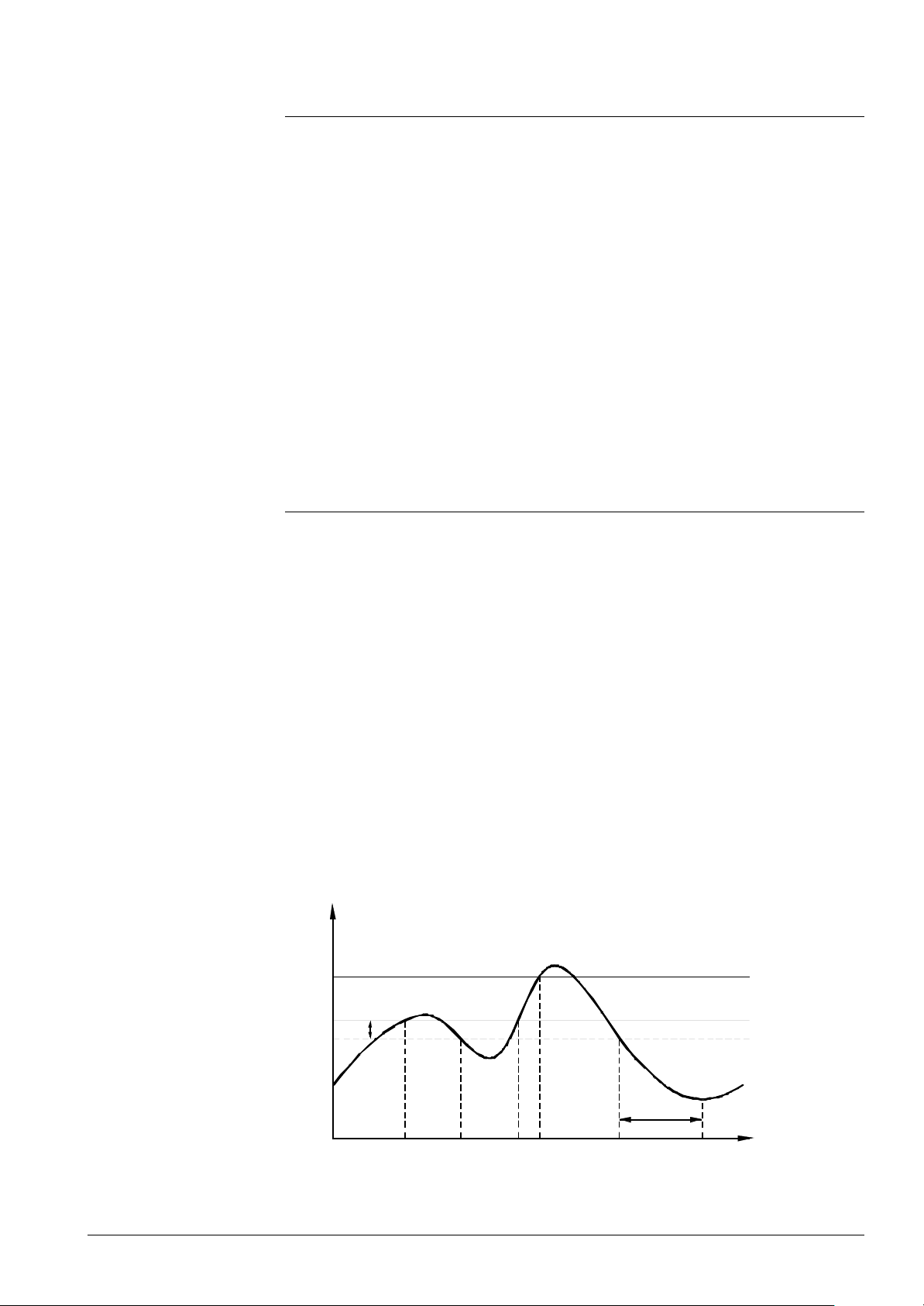
3.4 Supervisory functions
Temperature limiter
function
Flue gas temperature
supervision
Plausibility check of sensor
The temperature limiter overrides boiler control.
When a maximum boiler temperature is reached, the temperature limiter causes the
boiler to shut down and delivers a forced signal to carry the heat away from the boiler.
After the boiler has cooled down, the temperature limiter will again enable startup
commands.
Switch-off criterion: TkIst ≥ TkMax
Effects: Triggering shutdown
Triggering the forced signal to carry heat away from the
boiler
Switch-on criterion: TkIst < TkMax – SdHzEin
Effects: Enabling new startup commands
Disabling the force d signal (starting pump overrun if there is
no demand for heat)
The temperature limiter overrides the 2-position control. The maximum boiler temperature setpoint, the switching differentials and the cutout temperature of the temperature
limiter should match (also refer to section «2-position control»).
If a configuration with flue gas sensor was selected (KonfigRg3) and flue gas
temperature supervision was released (KonfigRg5), the LMU… must read in a valid
value for the flue gas temperature.
Otherwise, there will be either start prevention with error code or the unit will initiate
lockout (KonfigRg5).
Function
Flue gas temperature supervision is classified as non-safety-related and overrides boiler
control. If the first flue gas temperature threshold (TaBegr) is exceeded, the boiler’s
output will be reduced to its minimum.
If the second flue gas temperature threshold (TaAbschalt) is reached, the boiler will be
shut down. In that case, in accordance with parameterization (KonfigRg5), either start
prevention of at least 10 minutes (ZAueRuec) will be triggered or the unit will initiate
lockout.
The boiler will be released again only after the flue gas temperature has dropped below
a certain level.
The following graph shows the different phases of flue gas temperature supervision:
Tabgas
TaAbschalt
TaBegr
SdHzEin
Boiler output =
Pmin...Pmax Pmin Pmin...Pmax Pmin Pmin...PmaxP = 0 P = 0
7494d32E
T0
T1 T2 T3 T4 T5 T6
ZAueRuec
Time
Flue gas temperature supervision with the LMU...
39/171
Siemens Building Technologies Basic Documentation LMU54... / LMU64... CC1P7494en
HVAC Products 3 Functions 07.11.2002
Page 40
• Boiler output limitation will be triggered when: Tabgas ≥ TaBegr
• Boiler shutdown will be triggered when: Tabgas ≥ TaAbsch
• Boiler output limitation or shutdown
will be canceled when: Tabgas < TaBegr – SdHzEin
If flue gas temperature supervision responds, an error code or lockout code will be
displayed. In addition, a forced signal will be triggered.
In the case of boiler shutdown, the fan will overrun (ZGebNach).
To ensure that short-time crossings of the flue gas temperature threshold do not
immediately give rise to a response, the acquired flue gas temperature will be filtered
(τ ≈ 2 seconds).
Electronic (S)LT
The electronic (S)LT used with the LMU... consists of the following function blocks:
• Switching off in the case of overtemperature
• Conduction of a number of plausibility tests in order to be able to interfere in the
process in due time to avoid overtemperatures
• Conduction of tests in order to detect fault conditions, thus enabling the (S)LT to
initiate adequate actions
Note!
The 2 (S)LT sensors (flow and return) are safety-related sensors!
They must be located and fixed in a way that constant and even heat transfer is ensured
(during the entire occupancy time and also after replacement).
• The flow sensor must be fitted at a location that is representative of the maximum
boiler temperature!
• The return sensor must be fitted at a location that is representative of the return
temperature!
Following must be observed in connection with the flow and return sensors:
• Do not use clamping bands for fixing!
• When using a holding spring, cable strain relief must be provided!
• Screwed immersion sensors can be used without taking any extra measures
Note
Measures may be necessary to check proper heat transfer inside the boiler.
Make certain that parameterization is matched to the specific requirements of
the boiler(s) and plant!
The relevant boiler and plant regulations must be complied with!
We recommend the use of an external safety limit thermostat (connection to LMU-X3-01)
in the following cases:
− Boiler outputs > 120 kW
− Applications involving pressure class 3
Handling faults
The table below contains the faults that can occur. It also shows the related measures,
that is, whether start prevention or immediate lockout shall be triggered.
40/171
Siemens Building Technologies Basic Documentation LMU54... / LMU64... CC1P7494en
HVAC Products 3 Functions 07.11.2002
Page 41
Fault list and actions
Actions
Description of fault Function Operating state Lockout
Unfa-
Faulty
Short-circuit flow X X X 10
Open-circuit flow X X X 10
Measured value of flow not
plausible
Measured value of flow not
plausible
Short-circuit return X X X 10
Open-circuit return X X X 10
Measured value of return not
plausible
Maximum return temperature
exceeded
(S)LT cutout temperature
reached
Maximum temperature
gradient exceeded
Excessive ∆T
Return temperature above
flow temperature
TkIst < 0 °C X X X 10
TkIst > 124 °C X X X 10
TkRuec < 0 °C X X X 10
TkRuec > TSTB X X X 10
TkIst > TSTB
Burner is switched off
∆TkIst > TempGradMax
Switch burner off
∆ϑ > dTkTrSTB
Reduce output by 20 %
∆ϑ > dTkTrSTB + 8K
Reduce output to min.
∆ϑ > dTkTrSTB + 16K
Burner off
TkRuec > TkIst +
Sd_RL groesser _VL
(X) X X X
vora-
ble
X X X
X
X
X
X
Diagnosis /
fault display
Over-
temperature
Small heat
consumption
Start
prevention
Already
activated
by TW
Immedi-
ately
X
After
(min.)
After number
of faults
(in 24 h)
Parameter:
GrenzeNach
erwaermung
Parameter:
GrenzeGradi
ent
Parameter:
GrenzeDelta
T
Parameter:
GrenzeRL_gr
oesserVL
Legend
Fault handling routines
∆ϑ TkIst - TkRuec
∆TkIst Gradient of actual boiler temperature
If a fault occurs and the limit thermostat’s (TW) cutout temperature is reached, the
accumulated heat must be carried away from the boiler by activating the fan or the
heating circuit pump (if not yet running).
Response if the cutout temperature is reached:
• Pump and fan overrun
In the event the above faults occur, following applies:
If the TW cutout temperature «TkMax» (parameter) is reached, the heating circuit pump
will be activated to accelerate the dissipation of heat and optional heating circuits will be
forced to draw off heat .
If the (S)LT’s cutout temperature is reached, the fan will also be activated.
Both are active until the relevant trigger criterion is no longer present, the maximum time
being «ZGebNach» (parameter).
41/171
Siemens Building Technologies Basic Documentation LMU54... / LMU64... CC1P7494en
HVAC Products 3 Functions 07.11.2002
Page 42

Flow switch / water
pressure supervision
Input «Heating circuit monitor» permits the use of a flow switch or of water pressure
supervision through connection of the relevant switch. The following functions can be
parameterized:
KonfigRg5.1 KonfigRg5.0 Impact
0 0 Flow switch triggering lockout
0 1 Flow switch triggering start prevention
1 0 Pressure switch triggering lockout
1 1 Pressure switch triggering start prevention
Function of flow switch
Function of pressure switch
With this function, the switch closes when adequate amounts of water pass through the
boiler’s heat exchanger. Hence, the heating circuit flow switch may be evaluated only if,
in the case of demand for heat, water passes through the primary heat exchanger.
In the case of DHW heating, the heating circuit flow switch will not be evaluated with the
following systems:
System 4
36
52
68
The heating circuit flow switch test is always started when demand for heat is triggered
(internally or externally).
When the switch is closed, startup can immediately be initiated. When open, the LMU…
will lock startup after a waiting time of 12 seconds. Then, a change to start prevention or
lockout with the relevant diagnosis is made (status or error code).
If the switch closes after that period of time and start prevention was triggered, it will be
canceled again and delivery of the status code is suppressed.
If there is no demand for heat, there will be no evaluation of the heating circuit flow
switch during pump overrun or during a kick function.
In that case, input «Heating circuit monitor» watches the water pressure (water shortage
switch).
A closed pressure switch immediately enables the startup commands to the burner
control and control of the pumps. If the pressure switch is open, start prevention or
lockout will only be triggered after 12 seconds.
To ensure protection against water shortage, pump control will also be locked.
For the diagnosis, a status or error code is generated in that case.
If the water pressure rises again and there is start prevention, it will automatically be
canceled again and pump control enabled.
Pressure sensor
Plausibility check of pressure sensor:
If a configuration with water pressure sensor was selected (KonfigRg3) and water
pressure supervision was released (KonfigRg5), the LMU… must read in a valid value
for the water pressure.
Otherwise, there will be either start prevention with error code or the unit will initiate
lockout (KonfigRg5). In any case, the pump will be deactivated to prevent dry run.
Note
Only one of the 3 devices (flow switch, pressure switch or pressure sensor) can be used
for supervision. Combinations are not possible.
42/171
Siemens Building Technologies Basic Documentation LMU54... / LMU64... CC1P7494en
HVAC Products 3 Functions 07.11.2002
Page 43
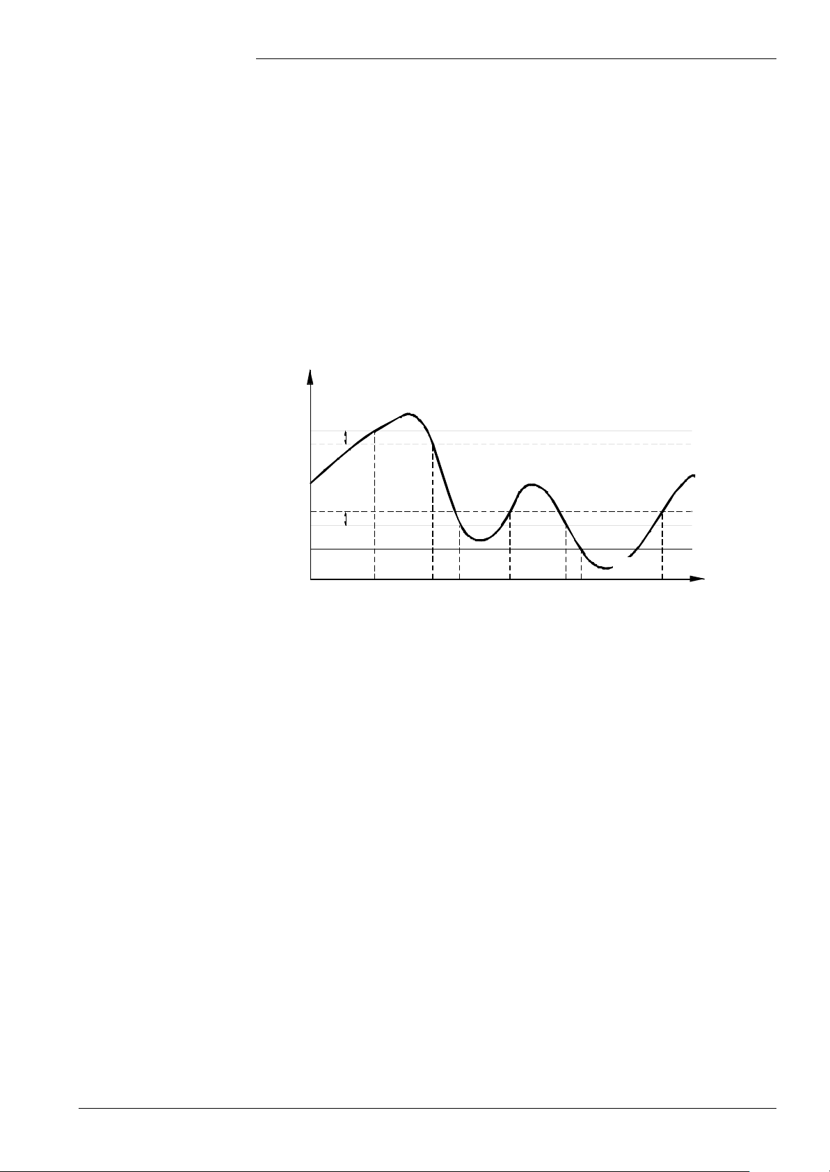
Static supervision
Function
If the pressure sensor is configured, the pressure switch or flow switch will no longer be
checked because water pressure supervision has the higher priority.
Water pressure supervision is overriding boiler temperature control.
When certain threshold values are crossed, the LMU… responds in one of the following
ways:
• Shutdown (PH2Omax), or
• Output reduction (PH2Omin), or
• Shutting down of boiler and pump (PH2OAbschalt)
If water pressure is too high or too low, there will either be start prevention or the unit
will initiate lockout, depending on the parameterization (KonfigRg5).
When water pressure returns to the permitted pressure range, the boiler will be released
with no delay. The following graph shows the various phases of water pressure
supervision:
Ph2o
PH2Omax
PH2OAbschalt
SdPH2O
SdPH2O
PH2Omin
Response =
None Shutdown None
7494d33E
T0 T1 T2 T3 T4 T5 T7
* Boiler
output - 20 % None * None
T6
Shutdown
and pump off
Time
Static water pressure supervision with the LMU...
• Boiler shutdown will be triggered when: Ph2o ≥ PH2Omax
• Boiler output limitation will be triggered when: Ph2o ≤ PH2Omin
• Boiler and pump shutdown will be triggered when: Ph2o ≤ PH2OAbschalt
• Boiler output limitation or shutdown will be canceled when: Ph2o < PH2Omax – SdPH2O
Ph2o > PH2Omin + SdPH2O
If water pressure supervision responds, an error code or lockout code will be displayed.
To ensure that short-time crossings of the water pressure thresholds do not immediately
give rise to a response, the acquired water pressure will be filtered (τ ≈ 2 seconds).
43/171
Siemens Building Technologies Basic Documentation LMU54... / LMU64... CC1P7494en
HVAC Products 3 Functions 07.11.2002
Page 44
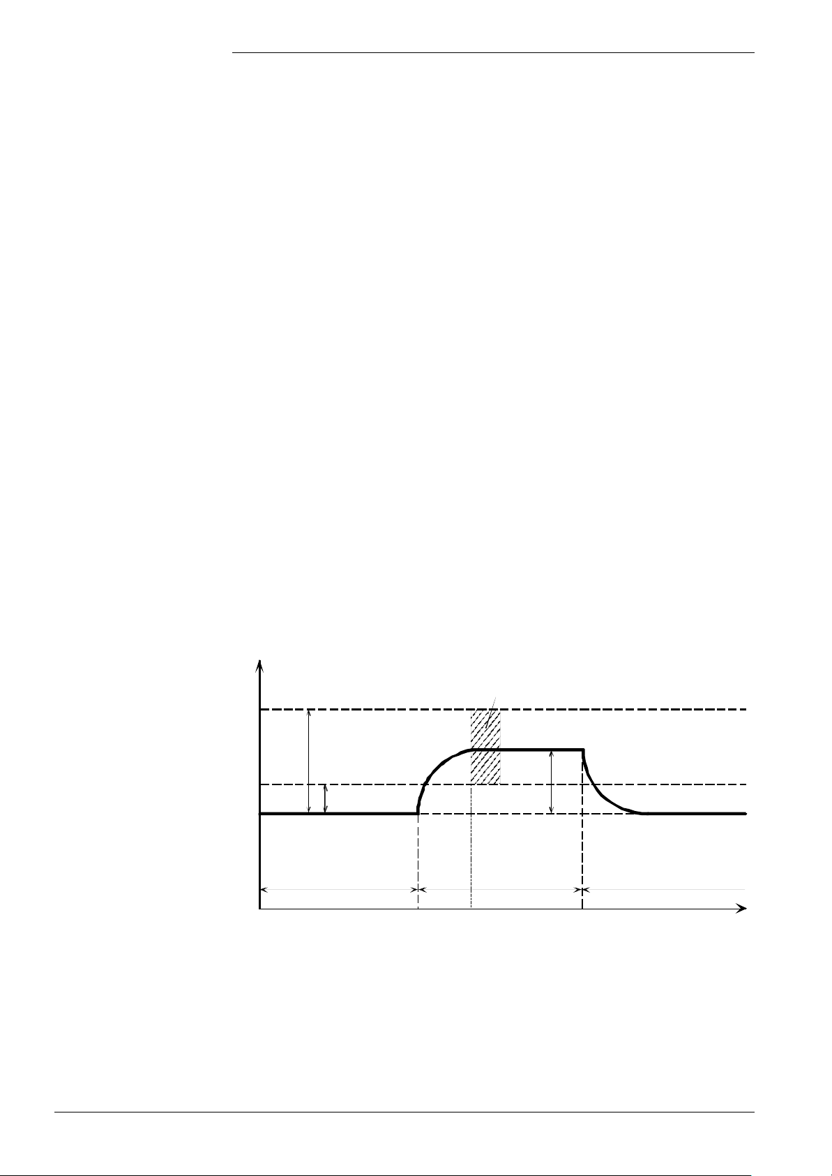
Time
Dynamic supervision
When a heating circuit pump is activated, the pressure downstream from the pump will
increase and the pressure upstream will decrease. These changes in pressure depend
on the pumping power and the pump’s capacity.
Function
Note
The pressure sensor acquires the pressure before and after the pump is switched on.
The pressure differential must exceed a minimum threshold (dpH2OminPuOn) to ensure
proper functioning of the pump.
At the same time, the same pressure differential may not exceed a maximum threshold
(dpH2OmaxPuOn) , which could lead to the indication of too little circulation or no
circulation at all .
If this criterion is not met, start of the pump will be prevented for 10 minutes, with
indication of the relevant signal code. If start prevention takes place 6 times in
successive order, lockout will be triggered if activated via parameter «KonfigRg5.7=1».
If the pump continues to run during start prevention, it will be locked for the last 10
seconds of start prevention, to be able to again acquire the pressure change caused by
the reactivation of the pump, after the boiler has been released again.
The pressure thresholds can be parameterized in the range from 0 to 5 bar, the
resolution being 0.02 bar. Checking of the pressure thresholds is individually switched
off by selecting 0 bar as the minimum value and 5 bar as the maximum value.
Parameter bit «KonfigRg4.3» can be used to define whether a pressure increase or
decrease will be expected after the pump is switched on.
If a diagram was configured without a pump Q1, the function must be deactivated.
The differential pressure is checked 8 seconds after the pump was switched on. Then,
during normal pump operation, the differential pressure will no longer be checked.
If a configuration with water pressure sensor was selected (KonfigRg3) and supervision
of water circulation has been released (dpH2Omin/maxPuOn), the LMU... must read a
valid value for the water pressure. Otherwise, there will be start prevention with the
relevant signal code or lockout will be triggered (KonfigRg5.7).
Valid pressure range
after pumpe on
dpH2OmaxPuOn
∆
dpH2OminPuOn
P
(e.g. 0.4 bar)
Ph2o filtered
Pump off Pump on Pump off
7494d40E/0702
T0 T1 T1+8 s T2
Dynamic water pressure supervision of the LMU...
44/171
Siemens Building Technologies Basic Documentation LMU54... / LMU64... CC1P7494en
HVAC Products 3 Functions 07.11.2002
Page 45
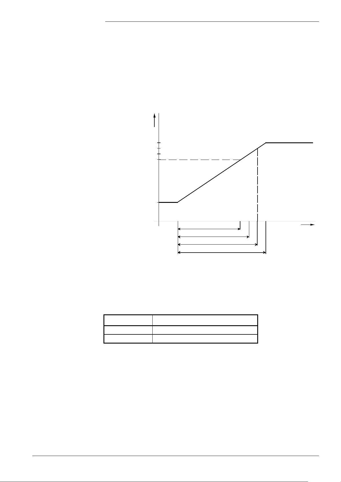
Load limitation
When defining the minimum and maximum heat output, the «Speed limitation» function
is of importance. This function is selected via parameterization:
KonfigRg5.2 = 0: Without speed limitation
KonfigRg5.2 = 1: With speed limitation
• Without speed limitation
In that case, the limit values selected for the setting range of heat output are the PWM
control values of the fan.
Supply voltage variations have an impact on the heat output and the fan will not catch
up. The maximum heat output or the modulating range can be determined with the help
of the following graph, depending on the type of plant components connected:
Heat output
(control of fan)
100 %
LmodVL
Max. heat output without RU
Max. heat output with RU
LmodTL
7494d01E
Modulating range of the LMU... without speed limitation
Modulating range with RU
Modulating range without RU
Modulating range d.h.w.
Max. modulating range
Output signal of
temperature controller
The output limits in the case of heat demand are dependent on the connection of a RU.
The following table shows the assignment:
RU Maximum heat output PhzMaxAkt
Present See calculations below
Not present PhzMax
Formula to be used for weather compensation without room influence via the RU:
PhzMaxAkt = • (PhzMax – LmodTL) + LmodTL
RelModLevSet
100 %
RelModLevSet: The relative modulation level setting specifies the maximum degree
of modulation of the RU in % of the modulating range.
45/171
Siemens Building Technologies Basic Documentation LMU54... / LMU64... CC1P7494en
HVAC Products 3 Functions 07.11.2002
Page 46

If there is demand for DHW, the maximum output is always predetermined by «LmodVL».
With regard to heat demand, the following thus applies to the modulating range:
Demand for space
heating
Minimum output LmodTL LmodTL
Maximum output PhzMaxAkt LmodVL
Demand for DHW heating
The maximum heat output can be adjusted on the HMI, QAA73... or PC tool using the
controller stop function.
The setting range is 0...100 %, whereby the following assignment applies:
0 % → LmodTL
100 % → LmodVL
When setting the maximum heat output, the following must be observed:
Maximum output in DHW mode: LmodTL ≤ LmodVL ≤ 100 %
Maximum output in heating mode: LmodTL ≤ PhzMax ≤ LmodVL
Maximum output in heating mode
and RU connected: LmodTL ≤ PhzMaxAkt ≤ PhzMax
46/171
Siemens Building Technologies Basic Documentation LMU54... / LMU64... CC1P7494en
HVAC Products 3 Functions 07.11.2002
Page 47
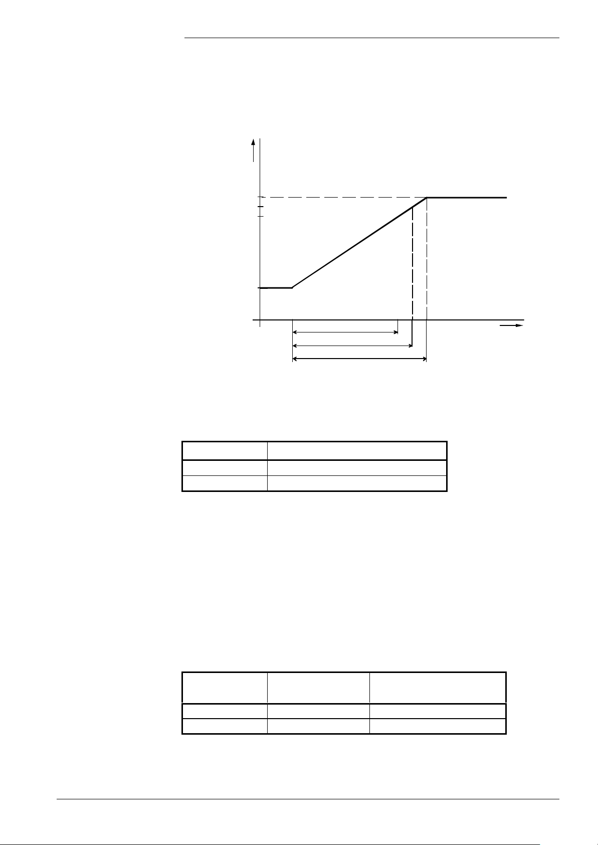
• With speed limitation
When speed limitation is active, disturbing effects on the fan’s speed (voltage variations,
changes in resistance on the flue gas side) will be offset with regard to output limits.
For that purpose, the associated speeds must be matched to the heat output measured
at the boiler. Like without speed limitation, the modulating range or the maximum heat
output can be specified in the form of fan speed.
Heat output
(fan speed)
Max. speed without RU
Max. speed with RU
Modulating range of the LMU... with speed limitation
N_VL
N_TL
7494d02E
Modulating range with RU
Modulating range without RU
Modulating range DHW
Output signal of
temperature controller
The output limits in the case of heat demand are dependent on the connection of an RU.
The following table shows the assignment:
RU Maximum heat output «NhzMaxAkt»
Present See calculations below
Not present NhzMax
Formula to be used for weather compensation without room influence via the RU:
RelModLevSet
NhzMaxAkt = • (NhzMax – N_TL) + N_TL
100 %
RelModLevSet: The relative modulation level setting specifies the maximum degree
of modulation of the RU in % of the modulating range.
If there is demand for DHW, the maximum output is always predetermined by «N_VL ».
With regard to heat demand, the following thus applies to the output or speed range:
Demand for space
heating
Minimum output N_TL N_TL
Maximum output NhzMaxAkt N_VL
Demand for DHW heating
47/171
Siemens Building Technologies Basic Documentation LMU54... / LMU64... CC1P7494en
HVAC Products 3 Functions 07.11.2002
Page 48

«NhzMax» can be readjusted during operation via the HMI. Using the controller stop
function, a setting range of 0...100 % is possible on the HMI, QAA73... or PC tool,
whereby the following assignment applies:
0 % → N_TL
100 % → N_VL
When setting the maximum heat output, the following must be observed:
Maximum output in DHW mode: N_TL ≤ N_VL
Maximum output in heating mode: N_TL ≤ NhzMax ≤ N_VL
Maximum output in heating mode
and RU connected: N_TL ≤ NhzMaxAkt ≤ NhzMax
Speed limitation
Note
Speed limitation maintains the preselected speeds when the maximum or minimum heat
output is reached. Disturbance variables with regard to fan speed are voltage variations
and changes in flueway resistance (length of flueways).
In the case of crossings of the maximum or minimum speed thresholds, speed limitation
acts like a one-sided speed control loop.
Depending on the demand for heat, the heat output range is thus as follows:
• With all types of heat demand: N_TL ≤ Nist ≤ NhzMaxAkt
The associated PWM setting range is: LmodTL...PhzMaxAkt
• With DHW demand: N_TL ≤ Nist ≤ N_VL
The associated PWM setting range is: LmodTL...LmodVL
LmodTL: Minimum modulation value at which the flame is not yet lost and
combustion performance is still satisfactory
LmodVL: Maximum permissible PWM value (parameter)
Speed limitation has 2 parameters («KpBegr» and « KpUnbegr»), which make it possible
to set the dynamics of speed limitation .
The parameter value of 10 represents the default setting.
Limitation of ionization
current
An additional limit is introduced for the ionization current (parameter «IonLimit»).
This limit is used to determine the minimum speed such that an ionization current fault
cannot cause the burner to shut down.
For that function, speed limitation must be active.
If parameter «IonLimit» is set to 0, the function is deactivated.
If the ionization current drops below «IonLimit», the minimum speed will be set to the
current speed.
When the function is activated, this speed will then define the lower limit for the speed
limitation. If the ionization current drops below that limit, the lower speed limit will be
raised by 100 min-1 every 10 seconds.
Speed limitation thus raises the PWM signal and the modulation, which leads to a higher
ionization current.
When the lower speed limit reaches the maximum speed («NhzMax» or «N_VL»), the
integrator will be stopped.
If the ionization current exceeds the limit, the speed limit is reduced again by 100 min
-1
every 10 seconds until the speed limit has reached the minimum speed (N_TL).
48/171
Siemens Building Technologies Basic Documentation LMU54... / LMU64... CC1P7494en
HVAC Products 3 Functions 07.11.2002
Page 49

3.5 Boiler control
fuel valves)
delay time
Boiler control comprises all functions that convert the demand signal (boiler temperature
setpoint) to the output signal (PWM fan control).
These functions include:
• The chimney sweep function ( → CC1B7494)
• The controller stop function ( → CC1B7494)
• Frost protection for the boiler
• 2-position control
• Modulating control
• Limitation and output of the manipulated variable
Frost protection
for the boiler
Controller delay
Controller delay due to
parameterization
Frost protection for the boiler is ensured independently of the demand for heat or the
connected plant components. It is therefore checked autonomously in the boiler control
and, if required, triggers startup with a forced signal to carry the heat away from the boiler.
• Activating frost protection for the boiler: TkIst < TkSfrostEin
When frost protection for the boiler is activated, the forced signal is delivered, thus
ensuring that the necessary amounts of heat are carried away from the boiler. The boiler
temperature setpoint for the PID controller used during frost protection for the boiler is
the maximum boiler temperature setpoint «TkSmax»:
TkSoll = TkSmax
This gives rise to a higher heat output, which means that the switch-off criterion will be
reached safely within a short period of time.
• Terminating frost protection for the boiler: TkIst > TkSfrostAus
If there is no other or no greater demand for heat, shutdown will be initiated when the
switch-off criterion is reached and the forced signal canceled so that pump overrun
starts.
When there is additional demand for heat, there will be no shutdown when frost
protection for the boiler is terminated.
The controller delay serves for stabilizing the combustion conditions, especially after a
cold start.
After release of the controller by the burner control, the latter maintains the
parameterized heat output (parameter «LmodRgVerz») for the period of time predefined
by parameter «ZReglVerz». The modulating controller and thus modulation are released
only when this period of time has elapsed.
The following graph shows an example:
Output
ZReglVerz
Ignition
LmodRgVerz
7494d06aE
t
Beginning
of startup
Siemens Building Technologies Basic Documentation LMU54... / LMU64... CC1P7494en
HVAC Products 3 Functions 07.11.2002
Ignition
(release of
Start of
controller
Start of modulation
by the load controller
49/171
Page 50
During the controller delay, the heat output in heating mode is limited to the heating
circuit’s correcting span («LmodTL...PhzMax» or «N_TL...NhzMax»).
The controller delay can also be activated via a flag (parameter «KonfigRg7» flag
«BetrArtRgVerz») in the case of
• DHW demand (with the exception of instantaneous DHW heaters)
whereby the parameterized output is limited to the possible correcting span of the
respective operating mode.
Controller delay due
to SLT criterion
Controller configuration
Transfer of setpoint /
actual value
If shutdown takes place due to a criterion of the electronic SLT - caused for example by
residual heat or a too rapid rise of the boiler temperature - a controller delay will be
activated with the next startup.
That controller delay lasts 30 seconds and is active only in heating mode or in the DHW
modes. During the time the controller delay is active, the following heat output is
delivered, depending on the parameterization.
KonfigRg7 - BetrArtRgVerz = 0: Minimum heat output
KonfigRg7 - BetrArtRgVerz = 1: Heat output «LmodRgVerz», which can be
parameterized
In operating modes «Chimney sweep», «Controller stop», or with the test function, the
controller delay due to an SLT criterion does not exist. But these operating modes can
activate the SLT criterion for the next startup.
Depending on the operating mode, the boiler controller must be loaded with the relevant
setpoints / actual values:
Heating mode DHW storage tank
charging
Setpoint Tsoll TkSoll TkSoll TempAnfoUfBw
Actual value Tist TkIst TkIst TbwIst1/ TkRuec or TkIst
Instantaneous DHW
heating
Determining the controller
coefficients
Parameter selection
In heating and DHW storage tank charging mode, the ascertained boiler temperature
setpoint is passed on. In the case of an instantaneous DHW heater, the DHW setpoint is
used. The actual values will be loaded.
With instantaneous DHW heaters, this is dependent on the type of hydraulic system,
water draw or comfort mode and the parameterization (KonfigRg2, DlhKomfReglF).
With fixed controller parameterization, only the relevant controller coefficients and the
respective sampling times are selected here.
Heating mode DHW storage tank
charging
Controller parameters
Kp, Tn, Tv
Sampling time ZabtastK ZabtastK ZabtastDlh
KpHz1, TnHz1, TvHz1 KpBw, TnBw, TvBw KpBw, TnBw, TvBw
Instantaneous DHW
heating
50/171
Siemens Building Technologies Basic Documentation LMU54... / LMU64... CC1P7494en
HVAC Products 3 Functions 07.11.2002
Page 51
Heat output limits
The PWM setting range of the temperature controller depends on the speed limitation
and the heat demand.
• With inactive speed limitation:
The modulating range must be parameterized while giving consideration to voltage
variations.
LmodTL:
This limit must be set such that the heat output will not fall below the minimum
permissible output while taking into account voltage variations (undervoltage).
PhzMax, LmodVL:
This limit must be set such that the heat output will not exceed the maximum
permissible output while taking into account voltage variations (overvoltage).
Heating mode DHW mode
Output limits with speed
limitation inactive
LmodTL, PhzMax LmodTL, LmodVL
In addition, the following requirement must be met: PhzMax ≤ LmodVL
• When speed limitation is active:
The modulating range of the temperature controller remains as wide as possible and
speed limitation limits the heat output to the required value.
- Upper limitation: «NhzMaxAkt» in the case of heating demand, «N_VL» in the
case of DHW demand
- Lower limitation: «N_TL» in the case of heating and DHW demand
To ensure a maximum modulating range will be reached and voltage variations in the
fan’s power supply can be offset, it is recommended to set the setting parameters of
output adjustment as follows:
LmodTL:
Minimum PWM value at which the flame is not yet lost (while giving consideration to
voltage variations).
PhzMax, LmodVL:
100 % (makes possible the maximum fan setting range).
If the associated speeds «NhzMax» and «N_VL» deviate too much from these PWM
values, there will be more and more overshoot when the fan speed attempts to adjust
itself on reaching the maximum heat output.
If such overshoot is not desired, the values can be reduced.
With the following operating modes, the heat output is statically predefined, that is, the
boiler controller’s results will be ignored and a value in accordance with the function is
delivered to the burner control.
Function Required heat output
Chimney sweep function PhzMaxAkt
Controller stop function Set on the HMI or QAA73...
Controller delay LmodRgVerz
51/171
Siemens Building Technologies Basic Documentation LMU54... / LMU64... CC1P7494en
HVAC Products 3 Functions 07.11.2002
Page 52

Boiler temperature control
2-position control
The 2-position controller generates the signal for startup or shutdown by the burner
control:
Startup = «On» at TkIst < TkSoll - SdEin
Shutdown = «Off» at TkIst > TkSoll + SdAus
The switching differentials will be loaded depending on the compensation variant. Also,
the dynamic switch-off differential has an impact on the value of «SdAus» .
Minimum boiler
pause time
The minimum boiler pause time locks the boiler for an adjustable period of time
«ZBreMinP».
This time commences after normal shutdowns or when the temperature limiter responds
in the case of heat demand, but the 2-position controller initiates a new startup only
when this period of time has elapsed.
• Release of minimum pause time:
After the flame signal is safely detected, the minimum pause time will be released, that
is, the pause time can be started by the 2-position controller with the next shutdown.
• Start of minimum pause time:
After release of the minimum pause time on shutdown by the 2-position controller or
temperature limiter, the timer will be loaded with the time «ZBreMinP» and then started.
• Interruption of minimum pause time:
If, during the minimum pause time, one of the following functions is called for, it will
immediately be started. In the background, the minimum pause time for the heating
circuit continues to run.
− DHW demand
− Frost protection for the boiler
− Controller stop function
− Chimney sweep function
If the demand is terminated during that period of time, the demand for heating will
continue to be locked until the minimum pause time has elapsed.
Boiler cycling protection
• Termination of minimum pause time:
− On completion of the minimum pause time
− When there is no more demand for heating (Hz1, Hz2 or HzZone)
− When a maximum control differential ∆T = «TkSoll – TkIst» is exceeded
If, during the boiler’s minimum pause time, the boiler temperature drops excessively, the
pause time will be terminated when a maximum control differential is reached and
startup will be released again.
∆T ≥ dTbreMinP
The minimum pause time will be restarted with the next shutdown.
Boiler cycling protection is accomplished with different methods, depending on the
operating mode.
Heating
mode
Dynamic switch-off differential X X X
Minimum boiler pause X
1)
= outlet temperature control
DHW storage tank Instantaneous
DHW heater
1)
52/171
Siemens Building Technologies Basic Documentation LMU54... / LMU64... CC1P7494en
HVAC Products 3 Functions 07.11.2002
Page 53
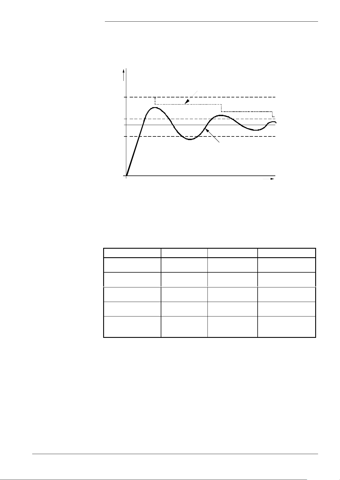
t
Dynamic switch-off
differential
To prevent unnecessary boiler shutdowns during the settling phase, the switch-off
differential is dynamically adapted depending on the temperature progression.
In principle, the switch-off differential is reduced depending on the extent of overshoot
in the settling phase. With aperiodic processes, the reduction takes place via a time
criterion. The following graph shows a typical settling process:
Tist
SdAus = f(Tist, SdAusMin, SdAusMax)
SdAusMax
SdAusMin
Tsoll
SdEin
Tist
7494d20/0201
Dynamic switch-off differential
The switch-off differential is thus a function of the maximum temperatures «Tist
SdAus» = f (Tist, SdAusMax, SdAusMin)
The switch-on differential is ready parameterized. Depending on the operating mode, the
following assignments apply:
Heating mode DHW storage tank Instantaneous DHW
Min. switch-off differential
(parameter)
Max. switch-off differential
(parameter)
Switch-off differential
SdAus
Switch-on differential
SdEin (parameter)
Time to reduction to min.
switch-off differential
(parameter)
SdHzAusMin SdHzAusMin SdBwAus1Min
SdHzAusMax SdHzAusMax SdBwAus1Max
=f(SdHzAusMin,
SdHzAusMax, TkIst)
=SdHzEin =SdHzEin =SdBwEin1
ZsdHzEnde ZsdBwEnde ZsdBwEnde
=f(SdHzAusMin,
SdHzAusMax, TkIst)
=f(SdBwAus1Min,
SdBwAus1Max, TbwIst1)
By setting the switching differential « SdHzAusMin» equal to «SdHzAusMax», or
«SdBwAus1Min» equal to «SdBwAus1Max», the dynamic switch-off differential can be
deactivated. The switching differentials are then adopted as ready parameterized.
Notes
A minimum switching differential of +2 K (SdAusMin, SdEin) must be observed.
The dynamic switch-off differential only works with positive values of SdAusMin and
SdAusMax!
53/171
Siemens Building Technologies Basic Documentation LMU54... / LMU64... CC1P7494en
HVAC Products 3 Functions 07.11.2002
Page 54
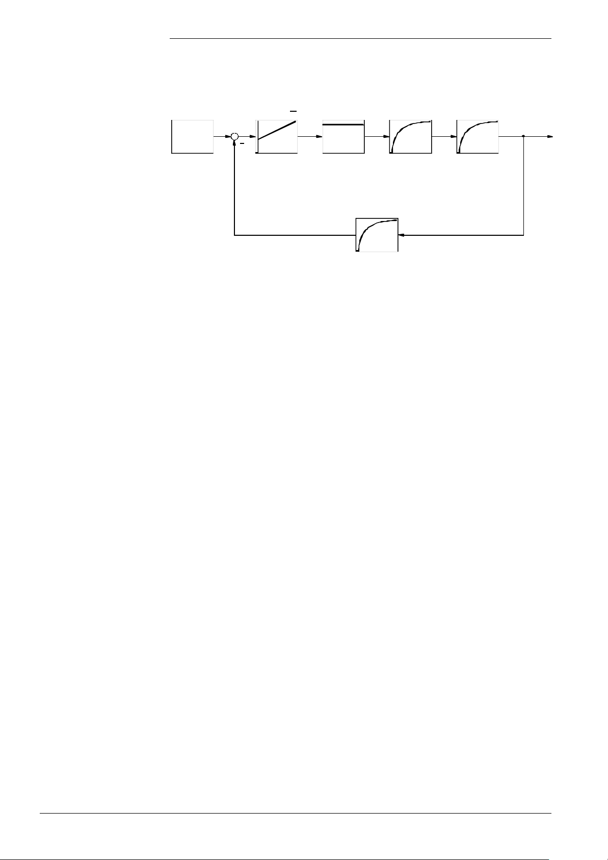
Modulating control,
conventional
The boiler circuit is a single temperature control loop:
Preset setpoint Controller
P
K
T∆
+
Boiler
setpoint
Tsoll
Adaption of
manipulated
variable
N
T
V
T
PWM
Fühler Fühler
Pneum. / el.
ratio control
Stell
K TStrecke
PWM
Sensor
TK
Burner and
heat exchanger
KK
Strecke
P
TIst
7494b06e/0201
Basic structure of boiler controller
In the boiler circuit, the boiler temperature is maintained at the predefined setpoint. The
controller can be used for the heating circuit or the DHW circuit.
The overriding 2-position controller releases the above mentioned control loop and
ensures that the predefined setpoint will be maintained.
The result of the temperature controller is matched to the PWM signal of the controlling
element. The output is adjusted via the fan and via pneumatic or electronic ratio control.
In all cases, the temperature limiter overrides the temperature control loop. This means
that the temperature limiter switches off the boiler when «TkMax» is reached (triggering
safety shutdown).
Based on the control differential (∆T = Tsoll - Tist) and the selected controller
parameterization, the PID control algorithm calculates the required manipulated
variable. Using the controller parameters, the relevant controller part can be activated /
hidden or adapted to the controlled system.
It is also possible to set the sampling time for the boiler circuit and the DHW circuit.
The heat output determined by the PID controller is limited to the permissible output
range.
54/171
Siemens Building Technologies Basic Documentation LMU54... / LMU64... CC1P7494en
HVAC Products 3 Functions 07.11.2002
Page 55
3.6 Hydraulic system management (HSM)
The HSM controls the controlling elements of the gas boiler and passes the demand
signal in a suitable form to the boiler control while giving consideration to boiler-specific
functions.
Frost protection
for the plant
Frost protection for the plant ensures protection when the outside temperature drops
below a certain level. When activated, the heating circuit pumps (Q1, Q2 and Q8, if
present) are directly activated so that the water in the heating circuit starts circulating.
Frost protection for the plant acts locally, that is, not on other heating zones of the
RVA46… These have their own frost protection.
In the case of DHW demand with absolute priority, that demand is given priority. If there
is no DHW priority, frost protection for the plant can be executed at the same time as
DHW heating.
Frost protection for the plant can be parameterized:
KonfigRg1.AnlagenFrost = 0: Frost protection for the plant deactivated
KonfigRg1.AnlagenFrost = 1: Frost protection for the plant activated
Frost protection for the plant uses the actual outside temperature. The type of response
depends on the outside temperature level.
If there is no outside temperature signal (LMU...-internal or external), frost protection for
the plant will be locked.
Outside temperature Impact on the heating circuits
TiAussen ≤ -5 °C Pumps on
-4 °C ≤ TiAussen ≤ 1.5 °C Pumps on for 10 minutes at 6-hour intervals
TiAussen > 1.5 °C Pumps off (if there is no other demand for heat)
In the temperature range -4...-5 °C, there can be different responses.
Decisive is the previous outside temperature level:
• If, before, the outside temperature was higher, the pumps will cycle in that range
• If, before, the outside temperature was lower, the pumps will remain activated in that
range
55/171
Siemens Building Technologies Basic Documentation LMU54... / LMU64... CC1P7494en
HVAC Products 3 Functions 07.11.2002
Page 56
Determining the
demands for heat
Priorization of demands
for heat
3.7 Consumer management (CM)
Consumer management includes the functions that relate to the interplay between the
consumer groups, also including external demands.
Examples are demands for heat resulting from space heating, DHW heating, or
demands resulting from operating actions.
Consumer management collects the various demands for heat from the consumer
circuits and ensures priorization. If required, several demands for heat are passed on:
• BwSpL DHW storage tank charging
• BwSpFs Frost protection for the DHW storage tank
• BwDlhA Instantaneous DHW heater, demand for outlet temperature
• BwDlhB Instantaneous DHW heater, standby demand
• BwDlhFs Instantaneous DHW heater, demand for frost protection
• BwSchS DHW stratification storage tank, quick charging
• BwSchL DHW stra tification storage tank, slow charging
• BwSchFs DHW stratification storage tank, frost protection
• Hz1 Demand for heat pump circuit / boiler circuit
• HzFs1 Demand for frost protection pumps / boiler circuit
• Hz2 Demand for heat mixing circuit / pump circuit 2
• HzFs2 Demand for frost protection mixing circuit / pump circuit 2
• HzZone Demand for heat from the zone (heating circuits via LPB)
• Aus No demand for heat
Priorization of demands for heat:
Priority Demand for heat with
absolute priority
1 BwDlhA BwDlhA
BwSpL BwSpL
BwSchS BwSchS
2 BwDlhB BwDlhB
BwSchL BwSchL
3 BwSpFs BwSpFs
BwDlhFs BwDlhFs
BwSchFs BwSchFs
4 Hz1
Hz2
HzZone
5 HzFs1
HzFs2
Demand for heat with
no priority
Hz1
Hz2
HzZone
HzFs1
HzFs2
Demands for heat of the same priority can be satisfied at the same time (if not excluded
by the hydraulic system). Subordinate priorities will be locked and must wait until the
higher priority is satisfied.
56/171
Siemens Building Technologies Basic Documentation LMU54... / LMU64... CC1P7494en
HVAC Products 3 Functions 07.11.2002
Page 57
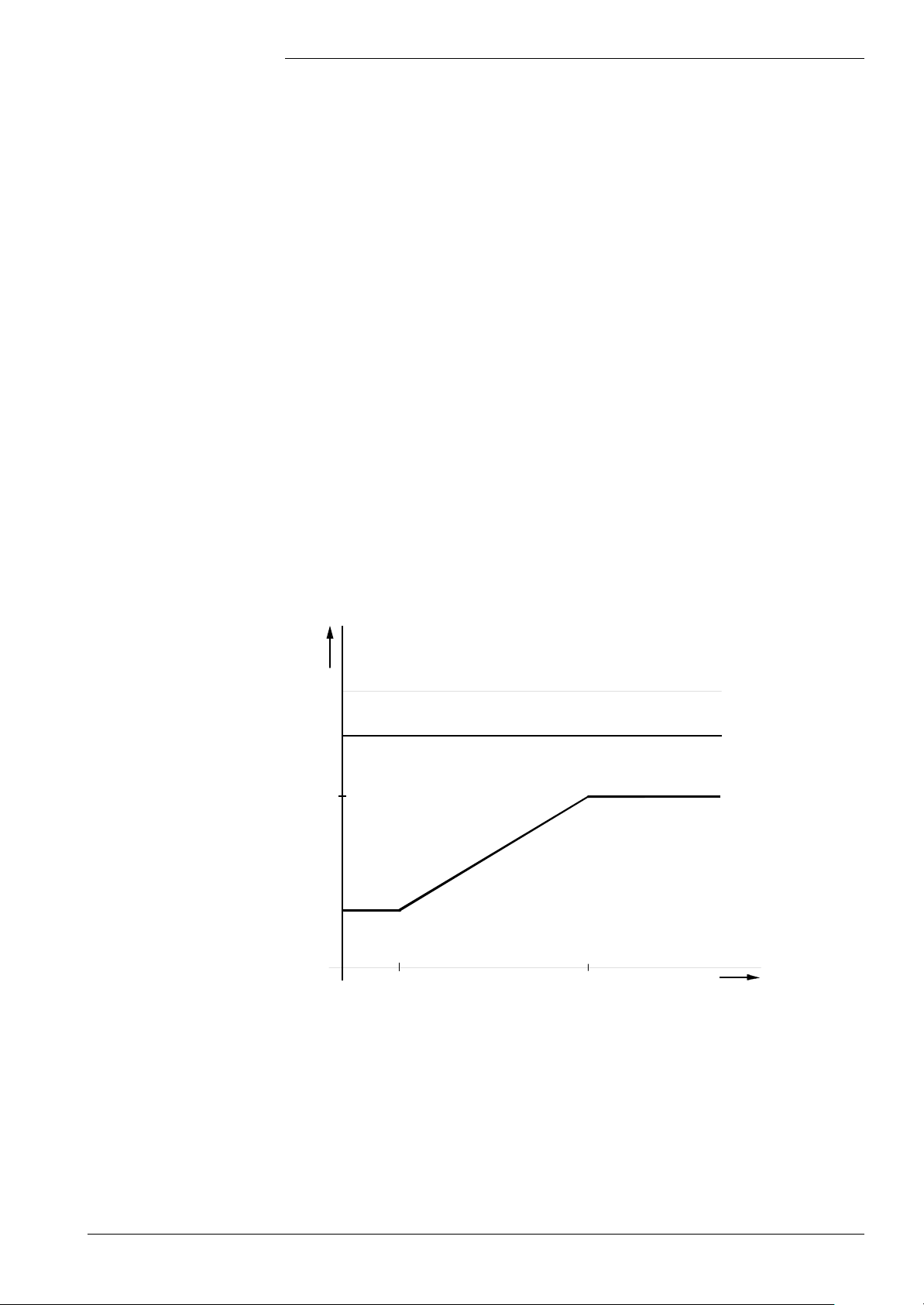
Determining the
temperature demand
Based on the temperature demands of the connected pieces of equipment, the CM
determines the resultant boiler temperature setpoint or, in the case of instantaneous
DHW heating systems, the DHW temperature setpoint.
The resulting temperature demand is produced from the maximum generation of all
available and released temperature demands, depending on the selected priority:
• No priority: Resulting temperature demand = max. (temperature
demand «HC1», temperature demand «HC2»,
temperature demand «ext. HC», temperature demand
«Bwk»)
• Absolute priority or all systems with instantaneous DHW heaters
- With heating demand: Resulting temperature demand = max. (temperature
demand «HC1», temperature demand «HC2»,
temperature demand «ext. HC»)
- With DHW demand: Resulting temperature demand = temperature demand
«Bwk»
The result obtained from the maximum generation must be restricted to the boiler’s
permissible temperature range. Depending on the parameterization, this may have an
impact on the temperature demand from the individual circuits.
If parameterization is correct, the permissible boiler setpoint range and setting of the
temperature limiter look as follows:
TkIst
Tstb
TkMax
TkSmax
TkSmin
TkSmin TkSmax
7494d12/0201
TkSoll
Correlation between 2-position control and temperature limiter
As the graph shows, the following conditions must be satisfied:
TkMax < Tstb
TkSmax < TkMax
57/171
Siemens Building Technologies Basic Documentation LMU54... / LMU64... CC1P7494en
HVAC Products 3 Functions 07.11.2002
Page 58
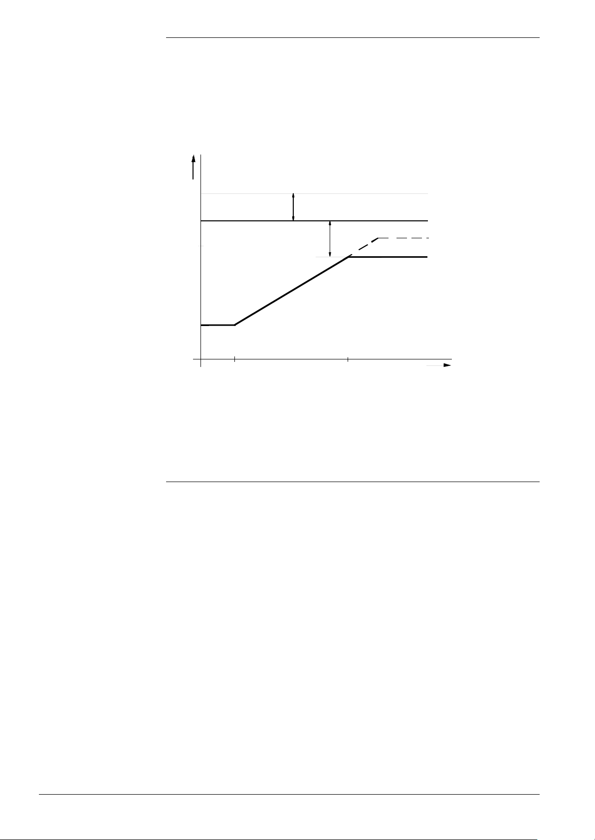
If the selected limiter cutout temperature is too high, internal limitation will be as follows:
TkMax = Tstb – 3K
If the maximum boiler temperature setpoint is selected too high and the switch-off
differential too wide (temperature limiter level reached), a minimum differential between
boiler setpoint and limiter cutout temperature must be observed:
TkSmax = TkMax – 3K
TkIst
Tstb
Min. difference to STB (3K)
TkMax
TkSmin
Min. difference to
temperature limiter (3K)
TkSmax
TkSmaxAktuell
Temperature limitation
TkSmin TkSmax
Limitation of the maximum boiler temperature setpoint by the temperature limiter
7494d13e/0102
TkSoll
In this case, the maximum boiler temperture setpoint is «TkSmaxAktuell». The greater
demand from the consumer circuits cannot be satisfied. If, after use of the CM, the
current switch-off differential «SdAus» is changed, the limitation is made one more time.
Heating circuit 1 can only be operated as a pump circuit. For this reason, limitation is
made for the range permitted for the pump circuit.
Limitation HC1: TkSmin ≤ temperature demand HC1 ≤ TkSnorm
Exception: → Warm air curtain function
58/171
Siemens Building Technologies Basic Documentation LMU54... / LMU64... CC1P7494en
HVAC Products 3 Functions 07.11.2002
Page 59

Summer / winter
(S / W) changeover
S / W changeover can be accomplished in 2 different ways:
1. With the manual switch on the HMI.
2. Through automatic S / W changeover via the outside sensor.
Notes on 1.: S / W switch
Depending on the type of HMI, a S / W switch is integrated. That switch causes central
locking of the heat demands of all heating circuits and a change to automatic S / W
changeover. The following states are possible:
1)
• Summer operation: All heating circuits locked
• Winter operation: All heating circuits released
• Automatic operation: The heating circuits are controlled via automatic S / W
changeover
1)
Also refer to CC1B7494 / Operation / HMI
Notes on 2.: Automatic S / W changeover (can be accomplished in several ways):
a) Via the RU (refer to Basic Documentation QAA73):
When an RU is used, that RU ensures automatic S / W changeover with regard to the
heating circuits connected to it (HC1 / HC2).
The LMU… has no information about the the RU’s S / W changeover state. In other
words, if the RU locks the heating circuits based on automatic S / W changeover, the
LMU… cannot release them again.
(If this is not desired, automatic S / W changeover of the RU must be deactivated by
setting a higher changeover temperature).
b) Via the LMU...:
The LMU… performs automatic S / W changeover of its active heating circuits
(heating circuits not controlled via the RU).
If the system uses an outside sensor (connected to the LMU… or to the RVA...), and
if a valid S / W changeover temperature was parameterized, automatic S / W
changeover becomes active.
Locking the demand for heat S / Wauto = 0 at TaGed > THG + 1K
(from winter to summer)
Releasing the demand for heat S / Wauto = 1 at TaGed < THG - 1K
(from summer to winter)
Automatic S / W changeover of the LMU… can be locked via parameterization:
At THG = 30 °C, automatic changeover is inactive and releases the demand for heat
in that case.
The current state of automatic LMU... S / W changeover is indicated on the HMI by an
LED.
The following table shows the correlation between the 2 automatic S / W changeover
facilities in the «Automatic» position of the HMI:
Automatic S / W
changeover RU
Summer Summer Locked Locked Locked
Winter Summer Locked Locked Locked
Summer Winter Locked Released Released
Winter Winter Released Released Released
Siemens Building Technologies Basic Documentation LMU54... / LMU64... CC1P7494en
HVAC Products 3 Functions 07.11.2002
Automatic S / W
changeover LMU
Impact on RU
HC(s)
Impact on LMU
HC(s)
Impact on the
zone
59/171
Page 60
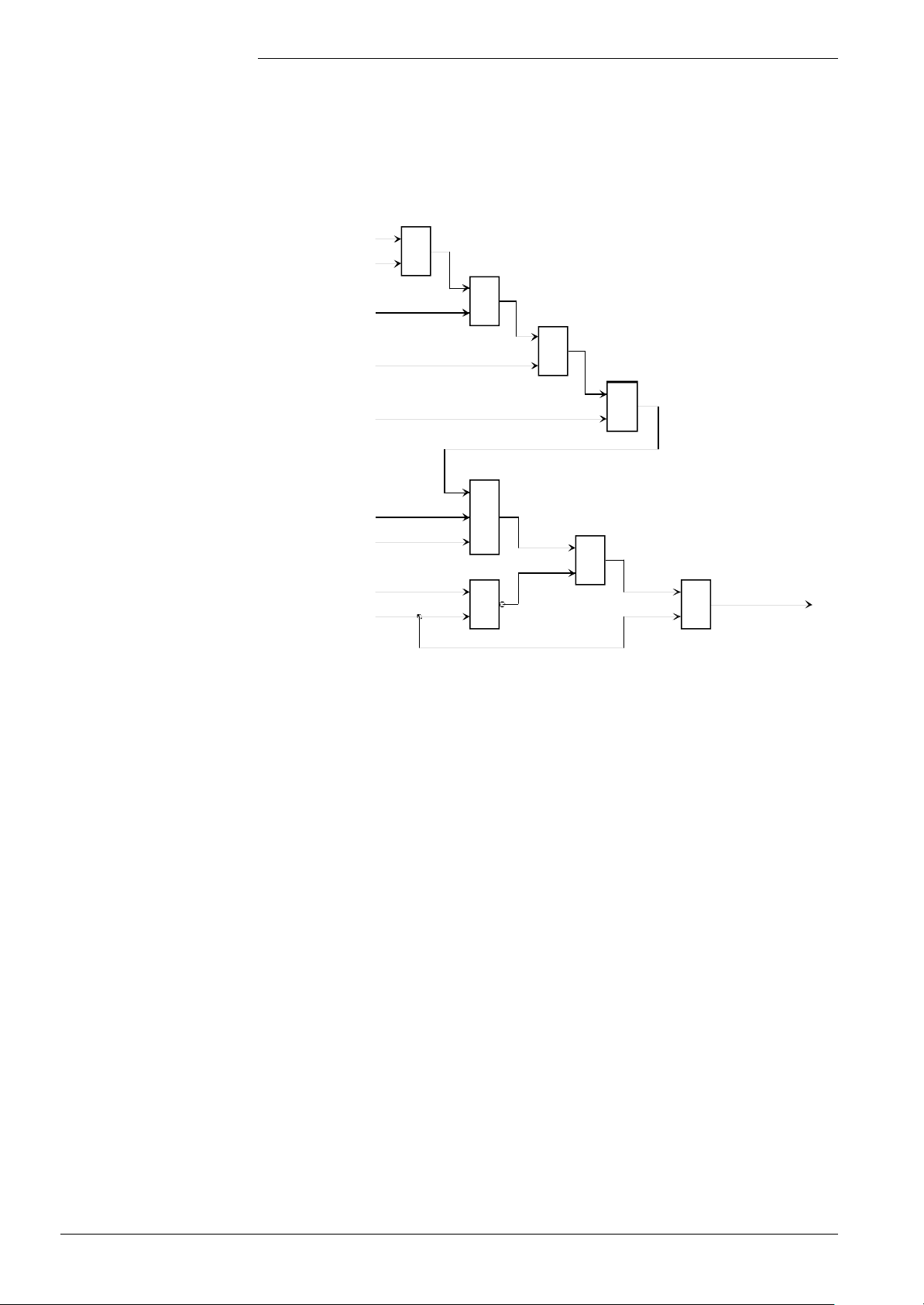
If no HMI is connected or if the HMI has no S / W switch, the decision on locking /
releasing is made exclusively via automatic S / W changeover.
If the system does not use an outside sensor either, all heating circuits will be released.
The following illustration shows the CM’s demand for heat in connection with automatic
S / W changeover:
S / W auto
S / W switch =
Auto
S / W switch =
winter (1)
Heat demand zone
Heat demand zone
per parameter
Heat demand HC1
Heat demand HC2
Absolute priority
DHW demand
&
≥
1
&
1≥
≥
1
7494b07E/0702
&
Resulting
heat demand
&
≥
1
Note
Resulting heat demand of CM
A description of summer / winter changeover with the AGU2.310... is given in
CC1B7494.
60/171
Siemens Building Technologies Basic Documentation LMU54... / LMU64... CC1P7494en
HVAC Products 3 Functions 07.11.2002
Page 61

3.8 Electronically controlled PWM heating circuit
pump
General
Introduction
Notes
In heating systems, the return temperature is the result of the
• amount of heat currently consumed,
• adjusted pump speed (multispeed pump), and
• current piping network characteristics
In the case of condensing boilers, well defined low return temperatures are required in
order to improve the efficiency of condensation.
However, the temperature differential between flow and return (∆T) should not be too
great since the heat exchangers should keep the differential within given limits.
Also, the maximum pump speed is hardly ever required (saving electrical energy and
reduction of noise in connection with thermostatic radiator valves).
∆T control acts on the PWM heating circuit pump and on the flow temperature setpoint:
1st stage: Maximum limitation of the flow temperature
2nd stage: ∆T limitation
3rd stage: ∆T supervision
A description of the control functions of stages 1, 2 and 3 is given in the following.
• A heating circuit pump with PWM is only supported in those hydraulic systems that
have a PWM pump included (refer to chapter 10).
If the selected hydraulic system that does not permit the use of a PWM pump, the
connected and parameterized pump will be controlled in a correspondingly stepwise
fashion via the PWM line
Task of ∆T control
with PWM pump
• Control of the PWM pump is based on weather-compensated flow temperature
control according to the heating curve.
If no weather compensation is active (no outside sensor connected), the default value
used is an outside temperature Ta of 0 °C on which the calculations will be based
If a modulating pump is used, adjustment of the pump speed alone does not suffice.
A different pump speed changes the volumetric flow through the heating plant and thus
the amount of heat delivered by the heating system .
This means that when the volumetric flow changes, the flow temperature must be
adjusted to the new situation.
In other words, it must be ensured that, at a given operating point, the amount of heat
delivered by the heating system must be the same although the volumetric flow
changes.
Since in the case of weather compensation, the heating curve defines the flow
temperature for a maximum volumetric flow, ∆T control should be based on that setting.
61/171
Siemens Building Technologies Basic Documentation LMU54... / LMU64... CC1P7494en
HVAC Products 3 Functions 07.11.2002
Page 62
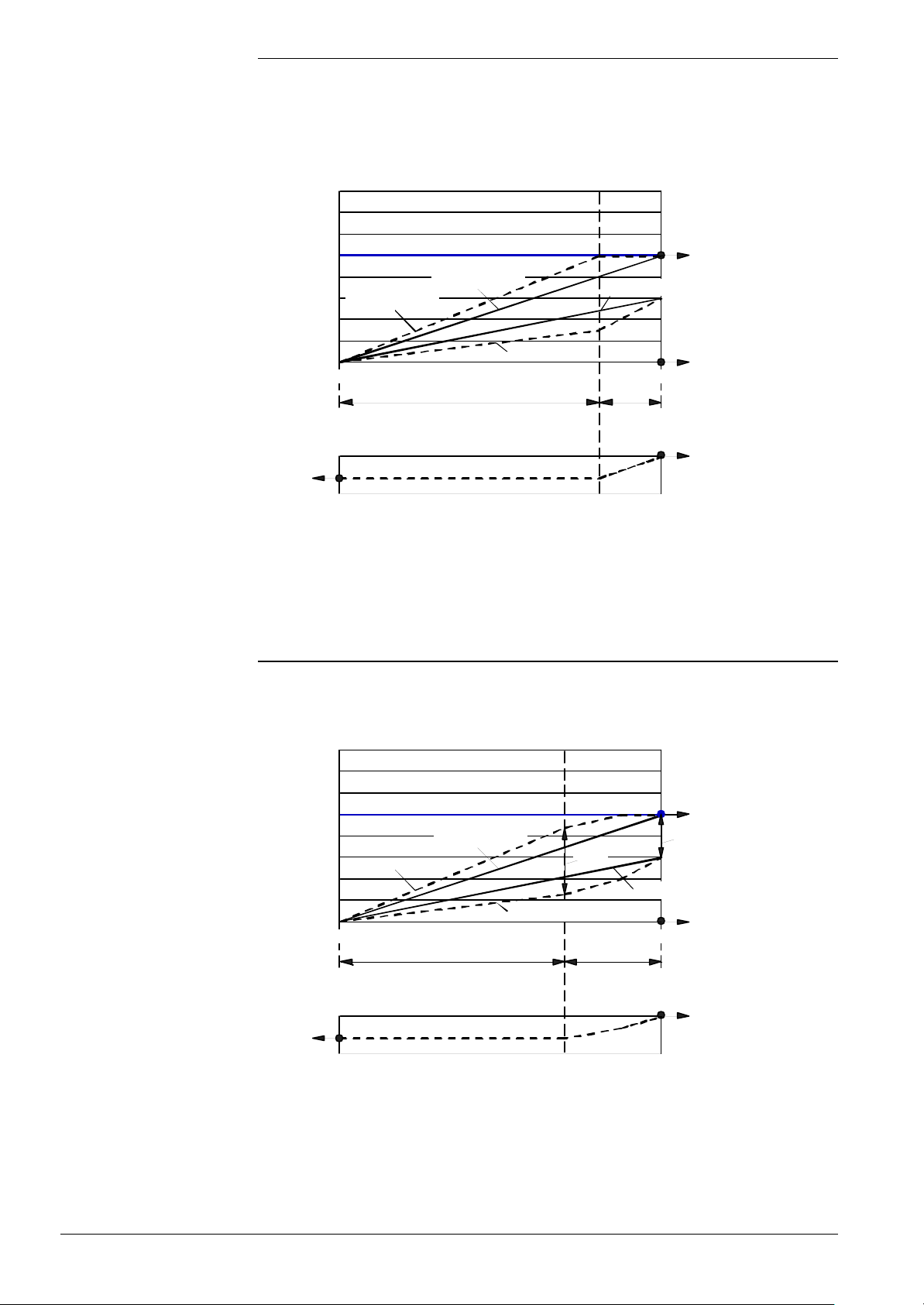
First stage
Maximum limitation of the
flow temperature
Operation with the minimum volumetric flow (NqmodMin) and calculation of the
associated flow tempeature boost to keep the amount of heat delivered by the heating
system at a constant level.
Limitation ot the maximum flow temperature (TkSnorm) by a stepwise increase of the
volumetric flow until the maximum volumetric flow is reached (NqmodNenn).
100
Modgrad [%]
NqmodMin
(= 40)
90
80
70
60
Required flow temperature
50
Temperature [°C]
40
30
20
at NqmodMin
20 15 10 5 0 -5 -10 -15 -20
Required flow temperature
at NqmodNenn
Theoretical return
temperature at NqmodMin
Outside temperature [°C]
Range of reduced volumetric flow
(= NqmodMin)
100
0
20 10 0 -10 -20
Outside temperature [°C]
Theoretical return
temperature at NqmodNenn
Range in which the
volumetric flow
must be increased
from NqmodMin
to 100 %
7494d34E/0102
TkSNorm
(= 70)
TiAussenNorm
(= -20)
NqmodNenn
(= 18)
corresponding to 100 %
Application
Second stage
∆T limitation
Maximum limitation of the flow temperature
Condensing boilers with no return temperature sensor to increase the efficiency of
condensation and when there are no limitations with regard to the heat exchanger’s
maximum ∆T. There should be no bypass, if possible.
Like the first stage plus limitation of the minimum volumetric flow to ensure the
expected ∆T will not exceed the adjusted ∆T (dTkTrMax)
→ Control of ∆Tmax via the volumetric flow.
100
Modgrad [%]
NqmodMin
(= 40)
90
80
70
60
50
Required flow temperature
Temperature [°C]
40
30
20
20 15 10 5 0 -5 -10 -15 -20
Required flow temperature
at NqmodNenn
Theoretical return
temperature at NqmodMin
dTkTrMax
(= 30)
Outside temperature [°C]
Range of reduced volumetric flow
(= NqmodMin)
100
0
20 10 0 -10 -20
Range in which the
volumetric flow
must be increased
from NqmodMin
to 100 %
Outside temperature [°C]
temperature at NqmodNenn
7494d35E/0102
TkSNorm
(= 70)
dTkTrNenn
(= 20)
Theoretical return
TiAussenNorm
NqmodNenn
corresponding to 100 %
(= -20)
(= 18)
∆T limitation
Application
Condensing boilers with no return temperature sensor to increase the efficiency of
condensation and when there are limitations with regard to the heat exchanger’s
maximum ∆T. There should be no bypass, if possible.
62/171
Siemens Building Technologies Basic Documentation LMU54... / LMU64... CC1P7494en
HVAC Products 3 Functions 07.11.2002
Page 63
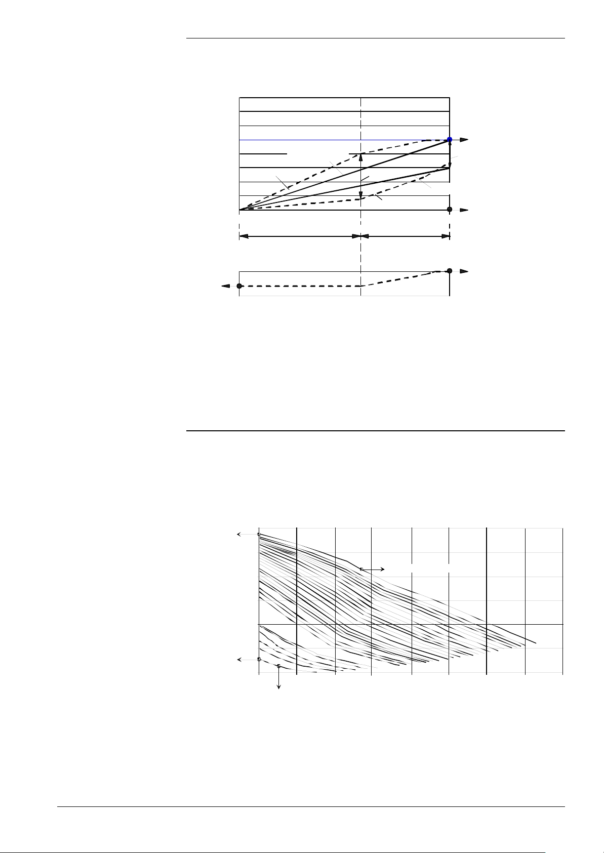
7494d37E/0102
Q [m3 / H]
Third stage
∆T supervision
Like the first stage plus limitation of the minimum volumetric flow to ensure the
measured ∆T will not exceed the adjusted ∆Tmax (dTkTrMax)
→ Control of ∆Tmax via the volumetric flow.
100
90
80
70
60
50
Temperature [°C]
40
30
20
Modgrad [%]
100
NqmodMin
(= 40)
∆T supervision
Required flow temperature
at NqmodNenn
Required flow temperature
20 15 10 5 0 -5 -10 -15 -20
Range of reduced volumetric flow
0
20 10 0 -10 -20
Outside temperature [°C]
(= NqmodMin)
Outside temperature [°C]
dTkTrMax
(= 30)
Acquired return
temperature
Range in which the delta-T controller
adjusts the volumetric flow
temperature at NqmodNenn
7494d36E/0102
TkSNorm
(= 70)
dTkTrNenn
(= 20)
Theoretical return
TiAussenNorm
NqmodNenn
corresponding to 100 %
(= -20)
(= 18)
Application
PWM pump control
H-Q chart
(example)
Condensing boilers with return temperature sensor to increase the efficiency of
condensation and when there are limitations with regard to the heat exchanger’s
maximum ∆T.
No bypass allowed.
• As before, the pump is activated and deactivated via the AC 230 V line. The pump’s
speed is adjusted via a separate control line
• The pump is controlled by means of a pulse width-modulated DC signal (PWM =
Pulse Width Modulation)
• Automatic maximum operation should the control line become faulty
FoerderMax
(= 5.9)
FoerderMin
(= 0.6)
6
5
4
Speed = QmodDrehzStufen
3
2
Pump head [m]
1
0
0.0 0.5 1.0 1.5 2.0 2.5 3.0 3.5 4.0
Speed = 1
H-Q chart of PWM pump
63/171
Siemens Building Technologies Basic Documentation LMU54... / LMU64... CC1P7494en
HVAC Products 3 Functions 07.11.2002
Page 64
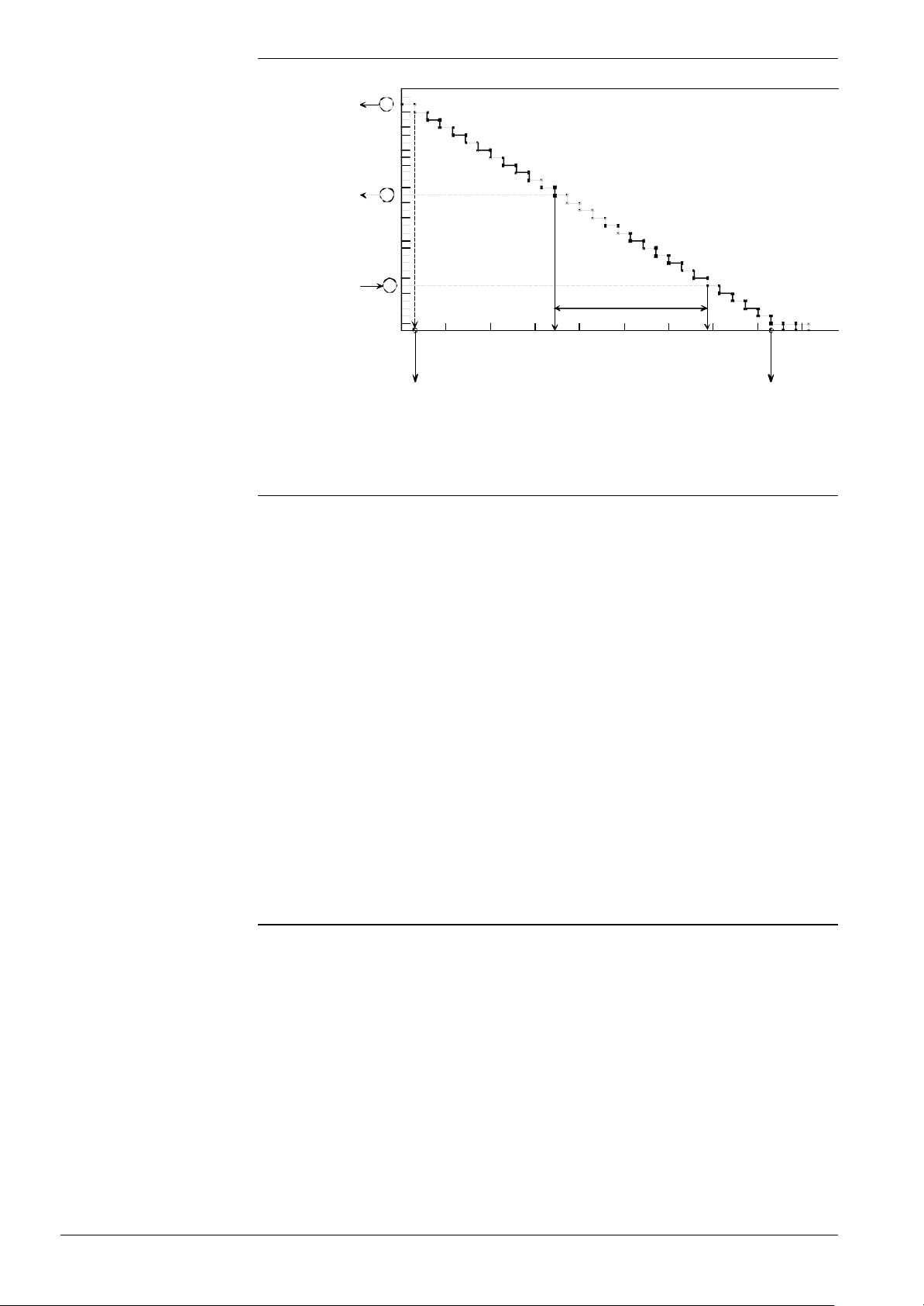
Adaption of modulating
pump to the heating plant
QmodDrehzStufen
(= 30 )
NqmodNenn
(= 18)
Speed [-]
Caculated
speed
for NqmodMin
(= 6)
32
30
28
26
24
22
20
18
16
14
12
10
8
6
4
2
0
0 10 20 30 40 50 60 70 80 90
100 %
Modulating range
of pump
NqmodMin (= 40)
7494d38E/0102
Parametes of the
PWM pump (OEM)
QmodDrehzStufen
QmodMin
QmodMax
FoerderMin
QmodMin
(= 3 %)
Degree of modulation (PWM) [%]
QmodMax
(= 82 %)
Adaption of modulating pump to the heating plant
Mandatory settings. Parameterization to be made by the OEM!
Number of speeds supported by the PWM pump. A minimum of 2 speeds need to be
set. This value can be obtained from the speed characteristic = f (PWM) or from the
pump supplier’s specifications.
Minimum degree of modulation of the PWM pump at maximum speed «QmodDrehzStufen» .
This value can be obtained from the speed characteristic = f (PWM) or from the pump
supplier’s specifications.
Maximum degree of modulation of the PWM pump at speed = 1.
This value can be obtained from the speed characteristic = f (PWM) or from the pump
supplier’s specifications.
Minimum pump head of the PWM pump (zero pump head at Q = 0) at minimum speed
(speed = 1) according to the supplier’s specifications. This value can be obtained from
the H-Q chart or from the pump supplier’s specifications.
FoerderMax
Maximum pump head of the PWM pump (zero pump head at Q = 0) at maximum speed
(speed = QmodDrehzStufen) according to the supplier’s specifications. This value can
be obtained from the H-Q chart or from the pump supplier’s specifications.
Preset parameters
Klambda1
To be readjusted only if required or in the event of problems!
Filter time constant of the digital filter used for filtering the actual values of the flow and
return temperatures for the ∆T supervision. This filter has a diminishing memory.
The default value of «Klambda1» is set to 0.99 ( τ ≈ 20 seconds).
KtAbtastDt
Factor for calculating the sampling time of ∆T control. The sampling time of ∆T control is
a multiple of the sampling time of boiler control (ZAbtastK).
The default value of «KtAbtastDt » is 10. If this parameter is changed, the controller
parameters must be adapted also.
64/171
Siemens Building Technologies Basic Documentation LMU54... / LMU64... CC1P7494en
HVAC Products 3 Functions 07.11.2002
Page 65

Activation of PWM pump
via a configuration byte
Parameterization to be made by the installer
Configuration byte for setting the control strategy of the modulating pump. For the ∆T
supervision, only Bits 0 through 5 are relevant.
Bit 0
Bit 1
Bit 2
Bit 5
Heating circuit pump or maximum limitation of the flow temperature (first stage).
XXXX XXX0: Multispeed pump is activated; the following Bits 1 through 5 have no
meaning
XXXX XXX1: Modulating pump is activated and thus maximum limitation of the flow
temperature also
∆T limitation (second stage)
XXXX XX0X: ∆T limitation is inactive
XXXX XX1X: ∆T limitation is active; maximum limitation of the flow temperature
remains active also
∆T supervision (third stage)
XXXX X0XX: ∆T supervision is inactive
XXXX X1XX: ∆T supervision is active; maximum limitation of the flow temperature
remains active also
∆T supervision in reduced operation
XX0X XXXX : The activated stage of ∆T supervision is inactive in reduced operation
In reduced operation, the pump will then generally operate at the minimum speed
«NqmodMin». When running at minimum speed in reduced operation, the house might
cool down excessively if poorly insulated.
Bit 6 and Bit 7
In the case of better insulated houses, this function is an additional savings function in
terms of electric pumping power, since the pump runs at a lower speed, thus saving
electrical energy.
XX1X XXXX : In reduced operation (night setback), the selected ∆T supervision is
active, depending on the activated stage
Not relevant for ∆T supervision.
Siemens Building Technologies Basic Documentation LMU54... / LMU64... CC1P7494en
HVAC Products 3 Functions 07.11.2002
65/171
Page 66

Parameters of the
PWM pump (installer)
NqmodNenn
Mandatory settings! Parameterization to be made by the installer.
Speed at the design point of the heating plant. This value must be set at the time the
plant is hydraulically balanced.
It corresponds to the speed of the circulating pump at the design point for reaching the
nominal volumetric flow.
This parameter corresponds to the analog speed selector of the circulating pump, so to
say.
For the control, setting of the «NqmodNenn» speed corresponds to the volumetric flow
of 100 % (= nominal flow at the design point).
The settings for the reduced volumetric flow («NqmodMin» and «NqmodMinBw») refer
to this 100 % value.
Parameters of the
PWM pump
NqmodMin
NqmodMinBw
Parameters for
temperatures
TkSnorm
Settings to be made if required.
Minimum speed of the PWM pump in heating operation that may be used so that a
sufficient supply of heat to the rooms is still ensured.
The adjusted percentage value is converted to a minimum characteristic depending on
the selected speed characteristic or the «NqmodNenn» speed.
This means that if «NqmodNenn» is changed, «NqmodMin» will automatically produce
another minimum speed for heating operation.
Minimum speed of the PWM pump in the case of stratification torage tank applications.
This pump speed is used when the stratification storage tank is fully charged.
The adjusted percentage value is converted to a minimum characteristic depending on
the selected speed characteristic or the «NqmodNenn» speed.
This means that if «NqmodNenn» is changed, «NqmodMinBw » will automatically
produce another minimum speed for DHW heating.
Mandatory settings! Parameterization to be made by the installer.
Maximum boiler temperature setpoint for the heating circuit. The maximum boiler
temperature setpoint or the nominal design temperature of the radiator heating system
refers to the design point at the design outside temperature «TiAussenNorm».
At the design outside temperature (lowest outside temperature), a 70 / 50 system is
designed based on a maximum boiler temperature of 70 °C.
This means that the «TkSnorm» setting to be made for a 70 / 50 system is 70.
TiAussenNorm
Design outside temperature at the design point of a heating plant.
The design outside temperature (lowest outside temperature) for the respective
geographical region can be obtained from appropriate tables (e.g. VDI-Wärmeatlas, DIN
standard).
The maximum boiler temperature setpoint «TkSnorm» will then be set according to the
design outside temperature.
dTkTrNenn
Mandatory setting!
Design differential (= temperature differential between flow and return) at the design
point at the design outside temperature. In the case of a 70 / 50 system, the setting to
be made is thus 20.
dTkTrMax
Setting to be made if required.
Maximum differential or ∆T between flow and return that shall be maintained by the ∆T
supervision.
66/171
Siemens Building Technologies Basic Documentation LMU54... / LMU64... CC1P7494en
HVAC Products 3 Functions 07.11.2002
Page 67
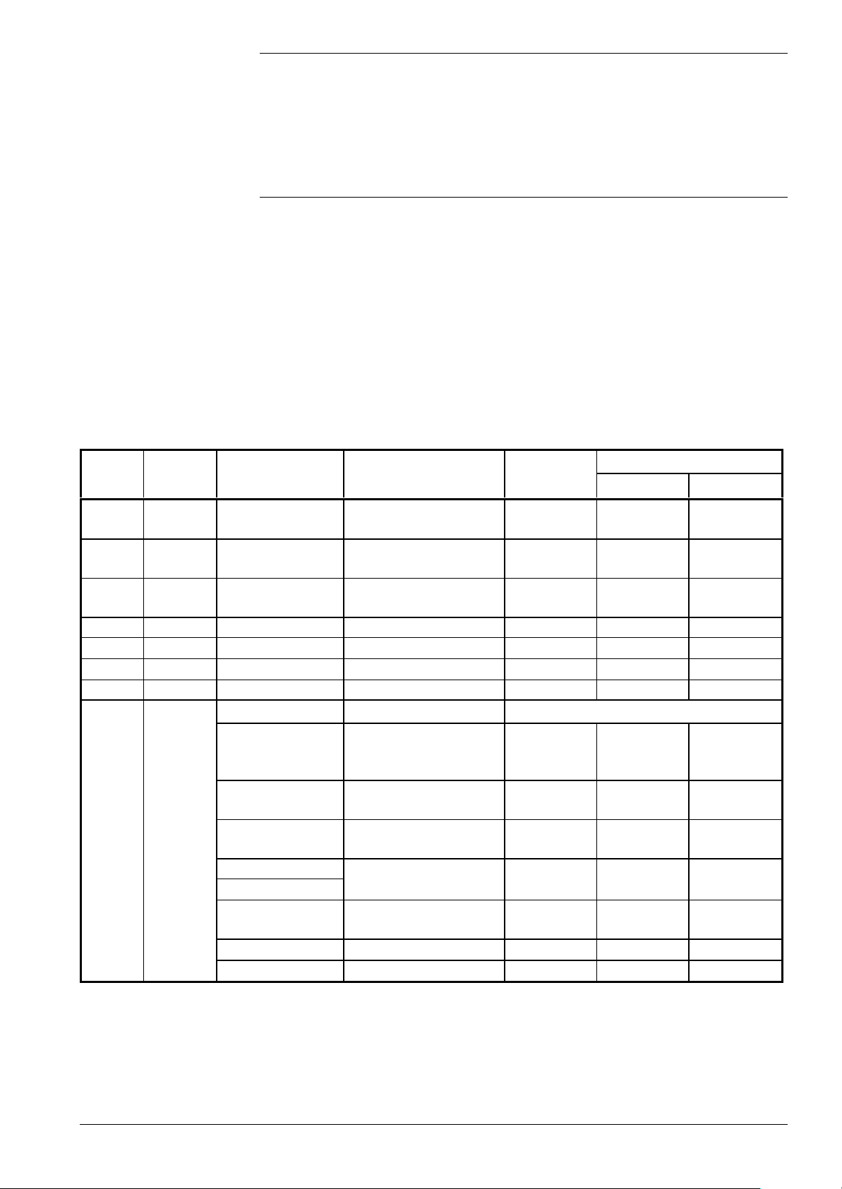
This value is used in connection with the ∆T limitation for controlling the pump’s degree
of modulation. With the ∆T supervision, «dTkTrMax» is the setpoint for the control of the
measured temperature differential between flow and return.
«dTkTrMax» can be set independently of «dTkTrNenn» and can even be greater than
«dTkTrNenn». When setting «dTkTrMax», the permissible temperature differential of the
associated heat exchanger must be observed.
PID controller coefficients
If required.
of delta-T supervision
KpDt
TvDt
TnDt
Proportional coefficient of ∆T supervision
Derivative action time of ∆T supervision
Integral action time of ∆T supervision
Summary of all ∆T
parameters
Mandatory settings
No. DPA no. Parameter name Function Setting level
OEM Installer
1 180 QmodDrehzStufen
2 146 QmodMin
3 147 QmodMax
4 177 FoerderMin Minimum pump head OEM Yes If required
5 176 FoerderMax Maximum pump head OEM Yes If required
6 435 Klambda1 Filter time constant OEM If required No
7 179 KtAbtastDt Factor for sampling time OEM If required No
KonfigRg7 Configuration byte
Bit 0
Bit 1
8 182
Bit 2
Bit 3
Bit 4
Bit 5
Bit 6 Not relevant Installer No No
Bit 7 Not relevant Installer No No
Number of speeds of the
modulating pump
Minimum degree of
modulation
Maximum degree of
modulation
Heating circuit pump
0: Multispeed;
1: Modulating
∆T limitation
0: Inactive; 1: Active
∆T supervision
0: inactive; 1: active
Plant volume
1,0: medium
∆T in reduced operation.
0: inactive; 1: active
OEM Yes If required
OEM Yes If required
OEM Yes If required
Installer Yes No
Installer Yes No
Installer Yes No
Installer No Yes
Installer Yes No
67/171
Siemens Building Technologies Basic Documentation LMU54... / LMU64... CC1P7494en
HVAC Products 3 Functions 07.11.2002
Page 68
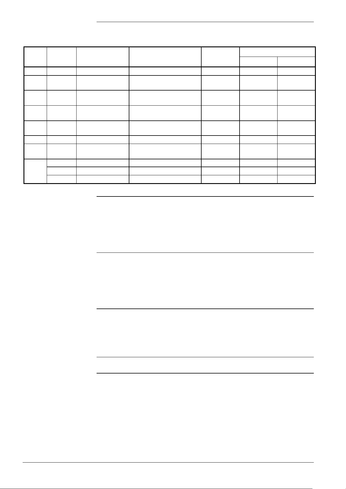
Summary of all ∆T
parameters (cont’d)
No. DPA no. Parameter name Function Setting level
Mandatory settings
OEM Installer
9 174 NqmodNenn Speed at the design point Installer No Yes
10 175 NqmodMin
11 188 NqmodMinBw
12 181 TkSnorm
13 173 TiAussenNorm
14 172 dTkTrNenn Design differential Installer No Yes
15 116 dTkTrMax
167 KpDt Proportional coefficient OEM No If required
168 TvDt Derivative action time OEM No If required16
169 TnDt Integral action time OEM – If required
Minimum speed in heating
operation
Minimum speed in DHW
operation
Maximum boiler temperature
setpoint
Design outside temperature
at the design point
Maximum temperature
differential of ∆T control
Installer No If required
Installer No If required
Installer No Yes
Installer No Yes
OEM Yes If required
Behavior in different
operating modes
Pump overrun
To ensure safe startup of the modulating pump, a start kick with the maximum pump
speed (QmodMin) is given for 10 seconds each time the pump is activated.
On completion of the start kick, the value calculated from the heat demand will be
adopted.
Normal operation
(heating operation)
Reduced (setback)
operation
Shutdown mode
Heating up phase
In normal heating operation, the pump runs at reduced speed (reduced volumetric flow)
for the greatest part of the operating time and the flow temperature will be appropriately
raised.
On the software side, both ∆T limitation and ∆T supervision can be switched on or off.
When the modulating pump is running, maximum limitation of the flow temperature
according to the adjusted value is always active.
In reduced operation, it is always the reduced (minimum) volumetric flow that is used, or
the ∆T supervison is active.
If the ∆T limitation and / or the ∆T supervision are active, they also acts in this operating
mode. It then works the same way as in normal operation, the only difference being the
lower flow temperature level.
The modulation function of the pump is deactivated since the heating is shut down.
In order not to extend the heating up phase due to the reduced volumetric flow, the plant
is always heated up with the full volumetric flow «NqmodNenn» within the first 30
minutes after reduced operation (night setback) or after plant shutdown (night
shutdown).
Then, a change to the volumetric flow is made that was calculated according to the
current outside temperature.
68/171
Siemens Building Technologies Basic Documentation LMU54... / LMU64... CC1P7494en
HVAC Products 3 Functions 07.11.2002
Page 69

DHW operation
temperature in connection
The maximum pump speed (QmodMin) will be used (with the exception of full charging
of stratification storage tank systems).
Behavior with night setback
or quick setback
If the LMU... knows about the states of the switching program, it is possible to run the
heating circuit pump at minimum speed during night setback or quick setback.
Decisive for this function is the compensation variant used.
In that case, it is accepted that the room temperature drops below the nominal level.
Energy savings are given priority.
Parameterization offers the following choices:
KonfigRg7.DtRedBetrieb =
XX0X XXXX : ∆T control is inactive in reduced mode, which means that the pump’s
speed is «NqmodMin»
XX1X XXXX : ∆T control is also active in reduced mode
Information about night setback is dependent on the compensation variant of heating
circuit 1. Depending on the variant, the function is either locked or released:
Compensation variant HC1 Criterion for night setback
Time switch is used and has made setback:
Emergency operation, fixed value control or
weather compensation LMU...
Room influence RU or weather compensation RU
«KonfigRg1.Schaltuhr1» = 1
and
RT = 0
Switching program of HC1 is in night setback
mode:
«BetrNiveauRh1»= 0 er 1*
Behavior with boostheating
Maximum limitation of the flow
with ∆T control
* BetrNiveauRh1 = 0 means frost protection
BetrNiveauRh1 = 1 means reduced mode (this means that the minimum pump speed
is also used in frost protection mode)
If the criteria for night setback are not met, ∆T control will be calculated and the
calculated pump speed delivered.
If the LMU... knows about active boost heating, it is possible to deliver the maximum
pump speed during boost heating (thus ensuring the shortest heating up time).
Information about boost heating is only possible in connection with the QAA73...:
Condition for evaluating boost heating:
Compensation variant Hz = (room influence RU or weather compensation RU) and
QAA73... present.
On completion of boost heating, the degree of modulation from the calculation of ∆T
control will be delivered again.
Depending on the connected plant components, the maximum flow temperature setpoint
«teta_vl_max» is generated based on the input from several sources:
Compensation variant HC1
Emergency operation, fixed
value control, weather
compensation LMU...
TkSnorm
(setting parameter of LMU…)
Room influence RU,
weather compensation RU
MaxTSet
(setting of RU)
Siemens Building Technologies Basic Documentation LMU54... / LMU64... CC1P7494en
HVAC Products 3 Functions 07.11.2002
69/171
Page 70
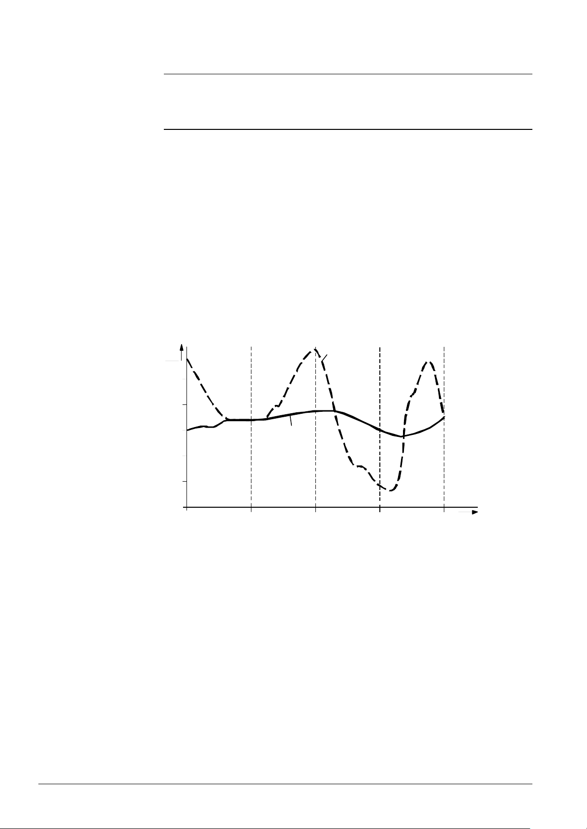
Attenuated outside
temperature
3.9 Heating circuit control
From the entries made by the endusers, room control determines the demand signal
delivered by the associated heating system. This takes place based on the results
obtained from weather compensation, switching programs, ECO functions, etc.
Benefit
Description
Setting
Process
Effect
Example
• Consideration is given to the building’s thermal storage capacity
The attenuated outside temperature is the simulated room temperature of a fictive
building that has no heat source and that is solely influenced by the prevailing outside
temperature.
No direct setting is possible. Generation of the attenuated outside temperature cannot
be influenced in any way.
The attenuated outside temperature is generated by the controller itself. It is calculated
at 10-minute intervals based on the actual outside temperature.
The attenuated outside temperature has a direct impact only on S / W changeover.
It acts indirectly on the flow temperature control via the composite outside temperature.
Ta
°C
17
16
15
14
TaGed
TiAussen
13
18:00 06:00 06:00 18:0018:00 t
TiAussen Actual outside temperature
TaGed Attenuated outside temperature
7494d22/0201
70/171
Siemens Building Technologies Basic Documentation LMU54... / LMU64... CC1P7494en
HVAC Products 3 Functions 07.11.2002
Page 71
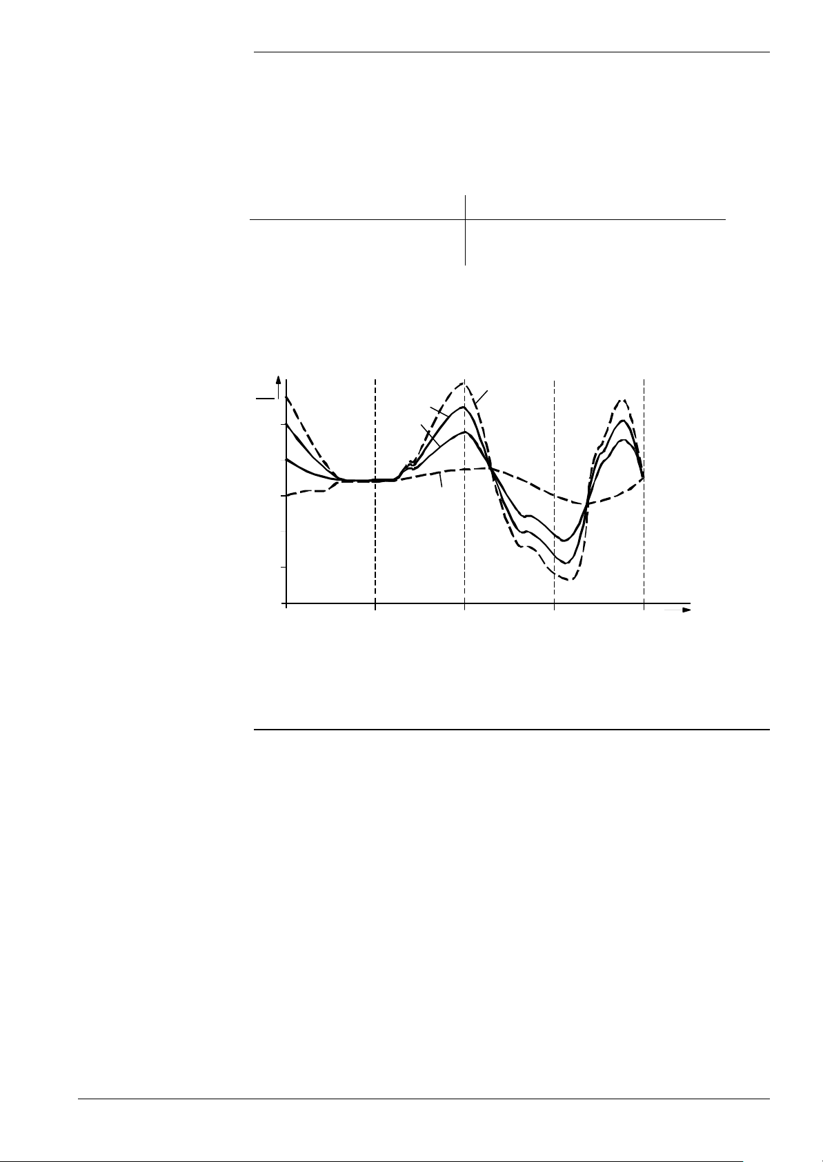
t
Composite outside temperature
Benefit
Description
Process
Impact
Example
• Compensating variable for flow temperature control
The composite outside temperature is a mixture of actual outside temperature and
attenuated outside temperature as calculated by the controller.
The mixture of actual and attenuated outside temperature is dependent on the type of
building construction and is generated as follows:
Selected type of building construction Composite outside temperature
Heavy TaGem = ½ TiAussen + ½ TaGed
Light TaGem = ¾ TiAussen + ¼ TaGed
The composite outside temperature acts on the flow temperature control as the
compensating variable, enabling the flow temperature to adapt to the prevailing weather
conditions.
Also, it acts on the automatic 24-hour heating limit to switch off the heating.
Ta
°C
17
16
TaGem1
TaGem0
TiAussen
Type of building construction
Benefit
Description
Impact
15
14
13
18:00 06:00 06:00 18:0018:00
TaGed
7494d23/0201
TiAussen Actual outside temperature
TaGed Attenuated outside temperature
TaGem1 Composite outside temperature of light buildings
TaGem0 Composite outside temperature of heavy buildings
• The building’s thermal storage capacity is taken into account
Allows the rate of control to be adapted to the type of building construction.
Depending on the thermal storage capacity of a building (type of building construction),
the room temperature changes at different rates as the outside temperature varies. This
setting adapts the generation of the composite outside temperature to the type of
building construction (also refer to «Attenuated outside temperature»).
Entry («KonfigRg4»):
XXXX XX1X: Heavy building construction. The room temperature responds more slowly
to outside temperature variations
XXXX XX0X: Light building construction. The room temperature responds more quickly
to outside temperature variations
Type of building construction
• Heavy building construction: Houses or buildings with thick walls or walls with
outside insulation
• Light building construction: Houses or buildings with thinner walls or light
brickwork
71/171
Siemens Building Technologies Basic Documentation LMU54... / LMU64... CC1P7494en
HVAC Products 3 Functions 07.11.2002
Page 72
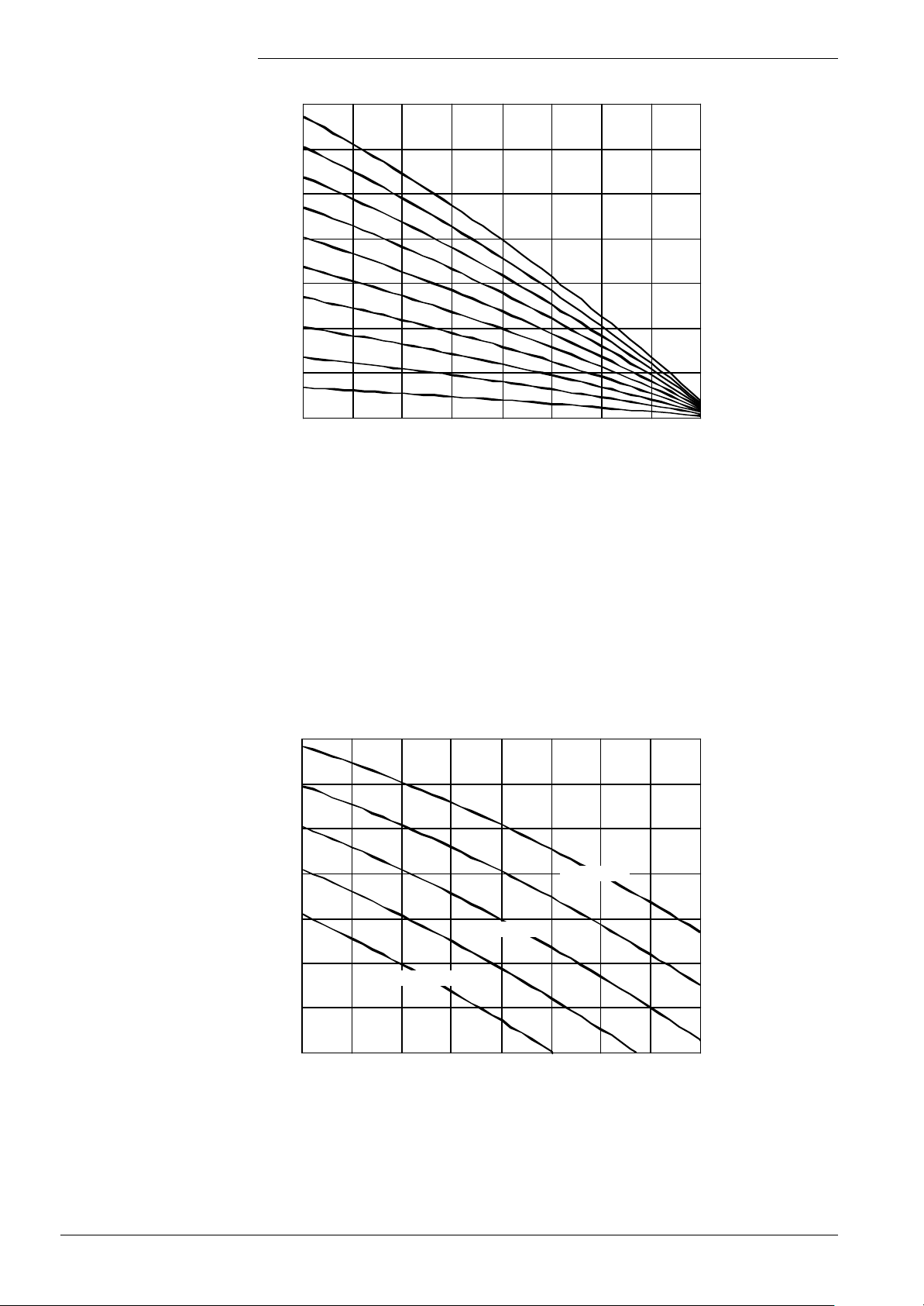
Composite outside temperature TaGem
Composite outside temperature TaGem
Heating curves
90
Heating curves (standard Siemens), TrSoll = 20 °C
80
Sth=20
70
60
Legend
50
40
Flow temperature setpoint TvSoll
30
20
-20 -15 -10 -5 0 5 10 15 20
Heating curves of LMU...-internal weather compensation (impact of slope)
Sth=10
Sth=2
7494d14e/0201
TvSoll: Flow temperature
TaGem: Composite outside temperature
Sth: Heating curve slope (parameter)
The heating curve describes radiator systems with a radiator exponent of n =1.3 at a
room temperature setpoint of 20 °C. For other systems with n = 1.1, for example, or
different nominal flow / return temperatures, the slope can be appropriately adjusted.
In the case of room temperature setpoint changes, the heating curve is shifted on a 45 °
axis in relation to TvSoll = f (TaGem) graph.
90
Heating curves (standard Siemens), Sth = 15
72/171
80
70
60
50
40
Flow temperature setpoint TvSoll
30
20
-20 -15 -10 -5 0 5 10 15 20
Heating curves of LMU...-internal weather compensation (impact of room temperature setpoint)
TrSoll = 10 °C
TrSoll = 20 °C
TrSoll = 30 °C
7494d15e/0201
Siemens Building Technologies Basic Documentation LMU54... / LMU64... CC1P7494en
HVAC Products 3 Functions 07.11.2002
Page 73
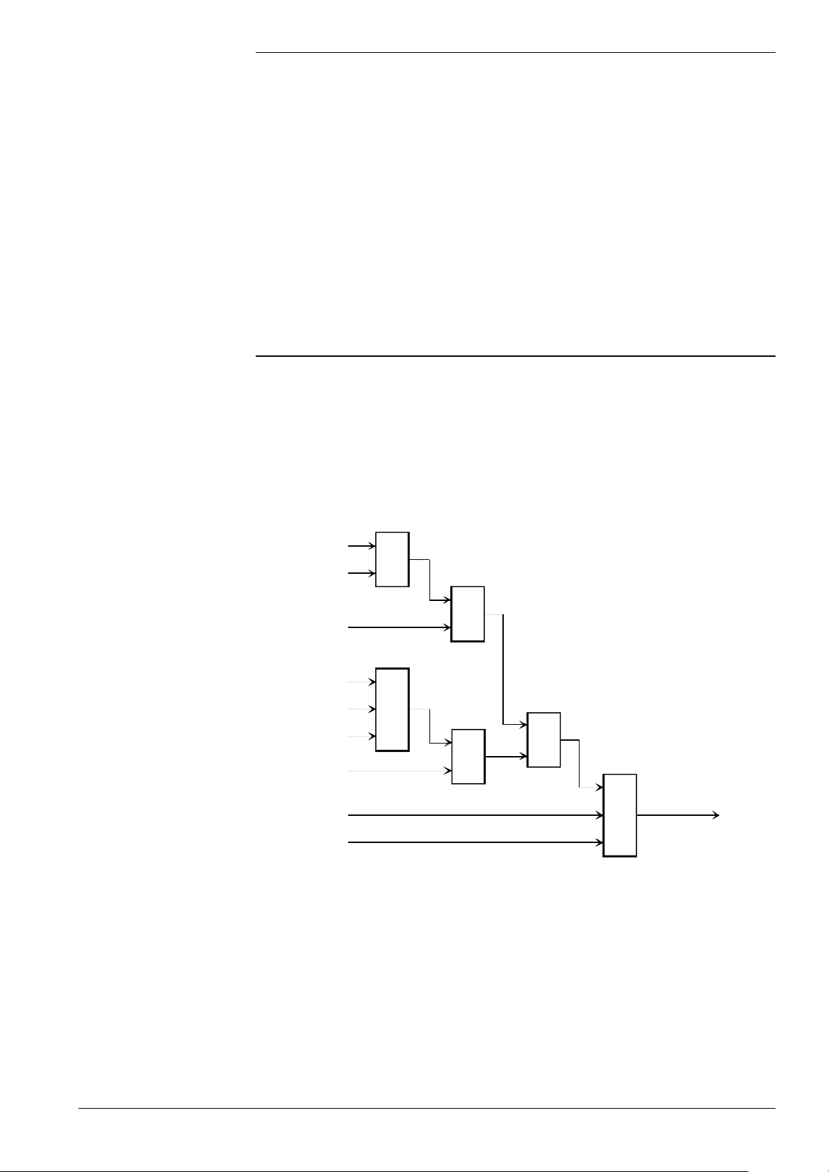
Calculation of the heating curve is based on a maximum pump flow rate, which means
With QAA73...
that the pump’s degree of modulation is 100 %.
When using a variable speed pump, a certain extra temperature is added.
RU QAA73... calculates weather compensation completely (referred to a degree of
pump modulation of 100 %). Input data from the RU’s perspective are the following:
Toutside: Actual outside temperature
As the results of weather compensation, the LMU... receives from the RU:
TSet: Boiler temperature setpoint of HC1 of the RU
TSet2: Boiler temperature setp oint of HC2 of the RU
CH1 enable: Heat demand HC1 of the RU
CH1 enable: Heat demand HC2 of the RU
To maintain the room temperature level with pump modulation, the LMU… calculates an
extra temperature, which is added to the value of the RU.
Generating the
demands for heat
If there are several sources that call for heat, the following priorities apply:
1. Demand for heat via the RU.
2. Room thermostat or time switch with / without weather compensation.
For the different plant components that act on the demand for heat, refer to the table in
chapter «Combinations of RU and room thermostat / time switch».
The → ECO functions also have an impact on the demand for heat.
In general, the heating circuits’ demand for heat is that shown by the following diagram:
S / W auto
S / W switch =
Auto
S / W switch =
winter (1)
RT / SU
Sab
HgS
RU
&
≥
1
&
7494b09E/0602
≥
1
&
≥
1
Heat demand
Legend
Heat demand
per Parameter
Only Rh1:
Warm air curtain
Generation of heat demand by heating circuits 1 and 2
RT / SU Room thermostat / time switch
HgS Heating limit switch
RU Room unit
S / W auto S / W changeover by LMU…
S / W switch S / W changeover on HMI
Sab Quick setback
If certain plant components are not present (e.g. no S / W changeover), the input will
enable the demand for heat.
73/171
Siemens Building Technologies Basic Documentation LMU54... / LMU64... CC1P7494en
HVAC Products 3 Functions 07.11.2002
Page 74
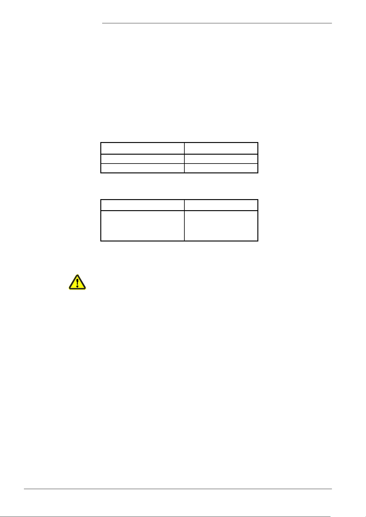
Time switch
In the case of systems using a time switch (external clock connected to the room
thermostat or QAA73... input), there are 2 choices to determine the demand for heat.
Changeover takes place via setting parameter «dTrAbsenk»:
dTrAbsenk = 0: Time switch acts directly on the demand for heat
dTrAbsenk ≠ 0: Time switch acts on the room temperature setpoint
Time switch acting directly
on heat demand
In this case, the switching state of the time switch contact is directly passed on. The
time switch can be connected either to the room thermostat or to the QAA73... input.
The following assignment applies:
Time switch contact open: SU = 0
Time switch contact closed: SU = 1
If no time switch is connected, the demand for heat will stay locked (SU = 0)
The assignment to the heating circuits is as follows:
Time switch connected to … Impact on …
RT input Heating circuit 1, SU1 = RT
QAA73 input Heating circuit 2, SU2 = OT
If a RU is connected to the QAA73... input, the following assignment applies:
Time switch connected to … Impact on …
RT input Heating circuit 1, SU1 = RT,
if not controlled by the RU
Heating circuit 2, SU2 = RT,
if not controlled by the RU
Time switch acting on the
room temperature setpoint
If SU2 is derived from the QAA73... input (no RU connected), SU2 will act on heating
circuit 2 only when parameter «KonfigRg1.Schaltuhr2Bw » = 0 and
«KonfigRg1.Schaltuhr2» = 1, that is, if a change to heating circuit 2 was made.
Otherwise, SU2 acts on the DHW circuit.
If, by contrast, SU2 is derived from the RT input (RU connected), the RU always acts on
heating circuit 2.
When AGU2.310... is connected, following applies: Time switch is inactive. It will be
replaced by the time switch program of the AGU2.310... ( → CC1B7494).
In this operating mode, the time switch produces a reduction of the room temperature
setpoint when the time switch contact is open. The room temperature setpoint changed
in this way is included in the calculation made by the heating limit switch. Hence, in this
case, the time switch only acts indirectly on the demand for heat.
If weather compensation is used, reduction of the room temperature setpoint also leads
to a reduction of the boiler temperature setpoint.
TsRaumAkt: Current room temperature setpoint
TsRaum: Room temperature setpoint from HMI or RU
dTrAbsenk: Temperature by which the room temperature setpoint shall be
lowered in reduced mode (setting parameter)
The room temperature setpoint «TsRaumAkt» changed in this way is included in the
calculation of the boiler temperature setpoint if weather compensation is used. The time
switch can be connected either to the room thermostat’s input or to the QAA73... inputs.
With regard to the time switch signal, the following applies, independent of the contact
position:
SU = 1
With this variant, the demand for heat is generated based on S / W changeover, heating
limit switch and quick setback .
74/171
Siemens Building Technologies Basic Documentation LMU54... / LMU64... CC1P7494en
HVAC Products 3 Functions 07.11.2002
Page 75
Room thermostat
In the case of systems that use a room thermostat, the switching state of that contact
decides on the demand for heat that shall be generated:
Input of room thermostat open: RT = 0
Input of room thermostat closed: RT = 1
If no room thermostat is connected, the demand for heat will stay locked (RT1 = 0).
The assignment to the heating circuits is the same as with the time switch:
Time switch connected to … Impact on …
RT input Heating circuit 1, RT1 = RT
QAA73 input Heating circuit 2, RT2 = OT
If a RU is connected to the QAA73... input, the following assignment applies:
Time switch connected to … Impact on …
RT input Heating circuit 1, RT1 = RT,
if not controlled by the RU
Heating circuit 2, RTR2 = RT,
if not controlled by the RU
RU
If a RU is connected, that unit decides on locking and releasing the heat demands from
the heating circuits controlled by it.
It is only S / W changeover that can override this demand.
The heating circuits not controlled by the RU can be operated by a room thermostat or
time switch. Both heating circuits of the LMU relate to the RT input since the QAA73...
input is used by the RU.
For the assignment to the evaluation logic, following applies:
Heating circuit 1
RU1 = 0: Demand for heat locked
RU1 = 1: Demand for heat released
Heating circuit 2
RU2 = 0: Demand for heat locked
RU2 = 1: Demand for heat released
75/171
Siemens Building Technologies Basic Documentation LMU54... / LMU64... CC1P7494en
HVAC Products 3 Functions 07.11.2002
Page 76
Combinations of RU and
room thermostat / time
switch
If, with regard to the switching program and the feedback signal from the room, different
plant components are connected, the following table applies for the assignment to the
heating circuits and the demands for heat.
When a RU is used, a room thermostat or time switch cannot be connected to that input.
For this reason, the table does not include these combinations.
Heating circuits of the RU are interpreted as nonexisting if, via the → configuration of
the heating circuits, they have not been parameterized as controlling heating circuits, or
if the heating curve slope has been deactivated.
Legend
RT1 or
SU1
Not present Not present – Not present Not present – –
Present Not present – Not present Not present RT1 / SU1
Not present Present Not present Not present Not present – RT2 / SU2
Present Present Not present Not present Not present RT1 / SU1
Present Not present Present Not present Not present RT1 / SU1
Not present Not present Present Present Not present RU1 –
Present Not present Present Present Not present RU1 RT1 / SU1
Not present Not present Present Not present Present – RU2
Present Not present Present Not present Present RT1 / SU1
Not present Not present Present Present Present RU1 RU2
Present Not present Present Present Present RU1 RU2
RT2 or
SU2
RU RU1 RU2
Heat demand
HC1
1) 2)
1) 2)
1) 2)
1) 2)
Heat demand
HC2
–
RT2 / SU2
RT1 / SU1
RU2
RT1 Room thermostat connected to RT input
SU1 Time switch connected to RT input
RT2 Room thermostat connected to OpenTherm input
SU2 Time switch connected to OpenTherm input and activated
(«KonfigRg1.Schaltuhr2Bw» = 0 and «KonfigRg1.Schaltuhr» = 1)
RU RU connected to OT input
RU1 Heating circuit of the RU, which controls heating circuit 1 of the LMU...
RU2 Heating circuit of the RU, which controls heating circuit 2 of the LMU...
– Present or not present
1)
1)
1)
1)
1)
Depending on parameter «KonfigRg1», time switch 1 / 2, following applies:
If this parameter = 1, time switch 1 / 2 is used
If this parameter = 0, room thermostat 1 / 2 is used
2)
If, with the AGU2.310, time switch operation is parameterized, the contact will not
be evaluated and replaced by the switching program of the operating section
76/171
Siemens Building Technologies Basic Documentation LMU54... / LMU64... CC1P7494en
HVAC Products 3 Functions 07.11.2002
Page 77
14:00
06:00
22:00
ECO functions
S / W changeover
Automatic 24-hour
heating limit
Benefits
Description
Introduction
Process
Since S / W changeover applies to all connected heating circuits, refer to «S / W
changeover».
• Automatic shutdown of heating
• Saving energy without sacrificing comfort
This is a fast-acting savings function since the heating will be switched off as soon as no
more heat is required. This ensures efficient operation throughout the year as there is
no need to switch off the heating manually – a special benefit during intermediate
seasons.
Without room influence
If no RU is connected, the room temperature setpoint will not be readjusted by the room
influence.
In that case, changeover of the automatic 24-hour heating limit takes place in
accordance with the adjusted setpoints.
The basic values used for the process are those of the composite outside temperature
and those of the current room temperature setpoint.
Switching off
Switching on
If the composite outside temperature exceeds the current room temperature setpoint,
the heating will be shut down.
Switch-off point of heating: TaGem = TRw
If the composite outside temperature drops by more than 2 °C below the current room
temperature setpoint, the heating will be switched on.
Switch-on point of heating: TaGem = TRw - 2 °C
T
°C
25 TaGem
TRw
TRw -2 °C
t
t
7494d26/0201
H
ON
OFF
20
15
10
5
0
06:0022:00
14:00
H Automatic 24-hour heating limit
TaGem Composite outside temperature
TRw Room temperature setpoint
Effect
During the time the automatic 24-hour heating limit is active, the heating will
automatically be off.
77/171
Siemens Building Technologies Basic Documentation LMU54... / LMU64... CC1P7494en
HVAC Products 3 Functions 07.11.2002
Page 78

Quick setback
constant (KON)
Benefit
Impact
Example
• Making use of the building’s ability to store heat
The duration of quick setback will be changed.
Entry:
Increase: Longer setback time;
for well insulated buildings that cool down rather slowly
Decrease: Shorter setback time;
for poorly insulated buildings that cool down quickly
Without room influence
Quick setback is started as soon as changeover to a lower room temperature setpoint
takes place.
The heating circuit pump will be deactivated until the quick setback time has elapsed.
That quick setback time is generated based on the setting of the composite outside
temperature and the room temperature setpoint step.
The quick setback time is limited to a maximum of 15 hours.
The example applies to a setpoint step of 4 K (e.g. from TRw 20 °C to 16 °C):
KON
TaGem 0 4 8 12 15 20
- 20 0 0 0 0 0 0
- 10 0 0.5 1 1.5 2 2.5
0 0 3 6 9 11 15
+ 10 0 5 11 15 (16.5) 15 (21) 15 (27)
Values are given in hours
Generating the
temperature demands
With fixed value control or
emergency operation
With weather compensation
Heating circuits 1 and 2 generate heat demands Hz1 and Hz2.
The heat demands are generated in different ways, depending on the configuration.
Also, the temperature demands are determined. They result from the user settings and
environmental conditions.
Fixed value control
The temperature demands result from the potentiometer position of the HMI.
Emergency operation
The temperature demands result from the calculation of the heating curve based on an
assumed outside temperature of 0 °C. This means that parameter «Slope» can be used
to exert an influence on the temperature demand.
There are different sources of weather compensation:
• LMU...-internal weather compensation:
LMU...-internal weather compensation will be activated when the outside sensor is
present, but no RU is connected. The heating curve parameters of the LMU… will be
used (STH1, STH2, DTR1, DTR2)!
• Weather compensation with the QAA73...:
The weather compensation of the QAA73... follows from the plant configuration.
In the case of weather compensation via the QAA73 ., the heating curve parameters
of the latter will be used which means those of the LMU… are not relevant!
For detailed information on the assignment of setpoints, refer to «Compensation
variants heating circuits».
78/171
Siemens Building Technologies Basic Documentation LMU54... / LMU64... CC1P7494en
HVAC Products 3 Functions 07.11.2002
Page 79

Functions
General
4 Clip-in AGU2.500... for additional
heating circuit
The description below covers the full functionality of the AGU2.500... system.
For the concrete scope of functions, refer to the relevant version / configuration.
• Additional pump or mixing circuit for single-user applications
• Independent heating circuit with own
− time switch program
− heating curve
− minimum / maximum limitation of the flow temperature
• Central operation of the 2 heating circuits via the QAA73...
• Straightforward attachment of clip-in module AGU2.500... to the housing of the
LMU6...
• RAST5 connectors for all inputs and outputs
Note
Hydraulic diagrams
Note
Sensor inputs
(analog inputs)
Maximum one clip-in module AGU2.500... can be connected to the LMU5... / LMU6... .
A maximum of 2 clip-in modules (OCI420 / AGU2.500... / AGU2.51x) can be connected.
On the LMU..., the respective hydraulic diagrams must be activated via parameter
«HydrSystem»:
• Pump circuit extensions: Diagrams 32 ... 47
• Mixing circuit extensions: Diagrams 48 ... 63
• Zone extensions: Diagrams 64 ... 79
With certain hydraulic diagrams using the AGU2.500... applications, an additional
actuating device Y1 (programmable output K2 of the LMU...) in the LMU… pump circuit
is used to ensure overtemperature protection.
• Flow sensor
The sensor used has a sensing element NTC 10 kΩ. Its characteristic is the same as
that of the NTC sensor read in by the LMU… basic unit.
Temperature Measuring range Read-in range Tolerance Resolution
Flow temperature 0...100 °C -5...125 °C ± 3 K 0.3 K
Note
Inputs / outputs
Siemens Building Technologies Basic Documentation LMU54... / LMU64... CC1P7494en
HVAC Products 4 Clip-in AGU2.500... for additional heating circuit 07.11.2002
The read-in tolerance is the worst-case device accuracy excluding the sensor tolerance.
Refer to «Connection diagrams».
79/171
Page 80

Interfaces for the LMU...
• Connect X50 of the LMU... and AGU2.500... via cable AGU2.104
• Connect AGU - X52 - 01 to X1 - 02 of the LMU... (mains supply)
Sensor
Frost protection
Overtemperature
protection
Mixing circuits
Determining the flow
temperature setpoint
If the sensor becomes faulty (open-circuit or short-circuit), it must be noted that the flow
temperature will no longer be controlled. The mixing valve will be driven to the fully
closed position (from V1.01).
The mixing valve clip-in module has its own frost protection function. This frost
protection of the heating circuit only covers the mixing circuit.
The frost protection for the heating circuit can only become active when a flow sensor is
connected to the mixing valve clip-in module.
If such a flow sensor is not present, or if it does not function correctly, the function
cannot be performed.
In mixing circuits, the maximum flow temperature that can occur will be limited:
- 55 °C up to V1.01
TvSmax V1.02 and higher
In the case of underfloor heating systems, a separate external limit thermostat must be
fitted to ensure protection against overtemperatures!
When there is an active demand for heat, the flow temperature setpoint is generated
from the temperature demand plus a boost when there is an active forced signal, or
minus a reduction when there is an active locking signal.
The forced signal has priority over the locking signal.
When frost protection for the heating circuit is active, the flow temperature setpoint is
generated from the switch-off threshold for frost protection.
If the heat demand for heating circuit 2 is not set, but a forced signal is present, the flow
temperature setpoint will be placed in the middle between «TvSmin» and «TvSmax».
Handling the locking signal
Handling the forced signal
Flow temperature
control
The basic unit generates locking signals when the current heat consumption is limited
by the consumers.
The purpose of these locking signals is to shut down or throttle individual load circuits to
enable the boiler temperature to rise more quickly.
If the locking signal exceeds a threshold value (5 %), the heat demand of all pump
heating circuits will be reset, thereby deactivating the pump of heating circuit 2.
If the second heating circuit is a mixing circuit (and is parameterized as such), any
locking signal causes the flow temperature setpoint to drop.
The basic unit generates a forced signal if there is a need for the boiler to carry surplus
heat away.
With the help of the forced signal, the heat shall reach the consumers as quickly as
possible.
When the forced signal is active, the basic unit sets the heat demand for all heating
circuits (including that for heating circuit 2).
The control used is 3-position control with delayed checkback. In connection with the
actuator, the control loop provides PI mode.
The flow temperature is controlled to the setpoint of the determined flow temperature
plus the boost.
80/171
Siemens Building Technologies Basic Documentation LMU54... / LMU64... CC1P7494en
HVAC Products 4 Clip-in AGU2.500... for additional heating circuit 07.11.2002
Page 81

Pump control
Pump control with
pump circuits
The pump is controlled via the mixing valve clip-in module. This also applies to pump
overrun and the pump kick.
Pump control with
mixing circuits
Pump overrun
Pump kick
Mixing valve control
In the case of a mixing circuit, the pump can also be activated by the mixing valve clip-in
module, independent of the LMU… (e.g. during frost protection for the heating circuit).
During pump overrun, the controller is also active. It maintains the flow temperature
setpoint that was valid prior to pump overrun. On completion of the pump overrun in the
case of mixing circuits, the mixing valve will be driven to the fully closed position.
After the pump kick in the case of mixing circuits, a kick is given to the mixing valve
actuator (pump is deactivated). The mixing valve will then be driven toward the fully
open and then toward the fully closed position.
The time of control toward the fully open position corresponds to the parameterized
actuator running time, and an additional 10 seconds toward the fully closed position.
The mixing valve clip-in module is suited for mixing valves equipped with a 3-position
actuator. This necessitates 3 states for the control of the mixing valve:
• Toward fully open
• Toward fully closed
• Unchanged
The running time of the mixing valve is to be parameterized on the LMU...
This actuator running time will be used for both the opening and the closing command
(symmetric actuator).
Position of mixing valve
in the idle state
Functional test
If, in the case of a system with mixing circuit, the controller of the mixing valve clip-in
module is not active - which means no pump control by the LMU… either (with the
exception of the pump kick) - the mixing valve will be driven to the fully closed position.
The duration of control depends on the paramererized actuator running tiem and is as
follows: 2 x actuator running time
After each reset, the mixing valve clip-in module automatically makes a functional test.
In the test, the mixing valve is first driven toward the fully open position (8 seconds) and
then toward the fully closed position (10 seconds).
Then, the output is used for the control of the pump (10 seconds).
81/171
Siemens Building Technologies Basic Documentation LMU54... / LMU64... CC1P7494en
HVAC Products 4 Clip-in AGU2.500... for additional heating circuit 07.11.2002
Page 82

Functions
General
5 Clip-in module OCI420... for
communication via LPB
• Communication clip-in module for connecting LMU5... / LMU6... to the ALBATROS
range of controllers via a LPB interface
• Connection of the LMU... to
− RVA46... zone controllers
− RVA47... cascade controllers
− RVA63... boiler and heating circuit controllers
− RVA65... energy managers for solar, wood, etc.
− RVA66... boiler and heating circuit controllers
− OCI6... communication interface for remote supervision (in connection with
suitable ACS... software)
1)
Planned; on request
1)
Note
Inputs / outputs
Interfaces to LMU...
Maximum one clip-in module OCI420... can be connected to the LMU5... / LMU6... .
A maximum of 2 clip-in modules (OCI420 / AGU2.500... / AGU2.51x) can be connected.
Refer to «Connection diagrams».
• Connect X40 of the LMU... and OCI420... via cable AGU2.104
5.1 Connection of LMU... to ALBATROS via OCI420
(LPB clip-in)
The connection of the LMU... to the ALBATROS system represents a functional
extension which, in principle, comprises 3 applications:
1. Additional heating circuits that are controlled by an RVA46..., RVA63... or RVA66...
2. Support of external DHW heating, provided the types of RVA... controllers used offer
this facility (e.g. RVA63... or RVA66...).
3. Use of the LMU... in a multiboiler plant (cascade) that is controlled by a superposed
cascade controller .
5.1.1 Additional heating circuit extensions via ALBATROS
controllers
ALBATROS heating circuit controllers, such as the RVA46…, make it possible to
connect additional heating circuits to the LMU...
In that case, the BMU acts as the heat supplier to one or several external consumers
that are controlled by the RVA…
All sensors, pumps and valves required for operating the external heating circuit will be
connected to the relevant ALBATROS controller that evaluates and controls them.
It is practical to also use that controller for making all settings required in connection
with the extension of the zone (setpoints, time switch programs, etc.).
For the operation of external heating circuits, an appropriate hydraulic diagram must be
selected on the LMU… Suitable choices are diagram 64 through 76.
82/171
Siemens Building Technologies Basic Documentation LMU54... / LMU64... CC1P7494en
HVAC Products 5 Clip-in module OCI420... for communication via LPB 07.11.2002
Page 83

Automatic changeover
of operating mode
Integration of the LMU... into the ALBATROS system includes automatic changeover of
the operating mode on the RVA... . .
It is activated when operating mode «Standb y» or «Manually summer» was selected on
the BMU or was triggered via modem.
In that case, the heating circuit operating mode on the RVA… changes automatically
and is indicated by a flashing «Standby» button.
Giving consideration to
heat demand from the
RVA…
Locking and forced
signals when connecting
to the LPB
The LMU… always takes into account the external heat demand from an RVA ... as long
as internal automatic summer / winter changeover does not call for summer operation
due to high outside temperatures.
This means that protective functions on the RVA..., such as frost protection for the room,
can become active also when, on the LMU…, the «Standb y» mode (manual summer
operation) was selected .
Although the operating mode of RVA… controllers normally is autonomous, the LMU…
can make use of locking and forced signals to influence the heat consumption of the
external user.
Locking signals that reduce heat consumption of the external heating circuits are
generated by the LMU... when DHW heating with absolute priority is active in the system
(on the LMU… or on one of the RVA...).
In that case, the RVA... will shut down their heating circuit pumps and drive their mixing
valves to the fully closed position.
If, however, the boiler temperature reaches a crucial level (e.g. temperature limiter cuts
out), the LMU… will generate forced signals that force the consumers to draw more
heat.
In response, ALBATROS controllers will activate the heating circuit pumps and open
their mixing valves .
In addition, the LMU… uses forced signals to trigger pump overrun in external heating
circuits. The duration of pump overrun is determined by LMU... parameter 130 -(ZqNach).
5.1.2 External DHW heating by ALBATROS controllers
In principle, application «External DHW heating» by an ALBATROS controller is not
much different from «Heating circuit extension». Nevertheless, a number of important
points need to be considered with this application.
In an interconnected system consisting of LMU…and RVA… controllers, several plant
components can manage DHW heating. At first, it does not matter whether one or
several units are involved in DHW heating.
Normally, a selection is to be made when the type of DHW heating is used as a
criterion. For example, ALBATROS controllers do not support instantaneous DHW
heating applications, but only storage systems.
DHW sensors, pumps and valves will be connected to the device that has been selected
for that function. This means that all settings required for DHW heating are to be made
there (setpoints, time switch programs, etc .).
Provision of external DHW heating by ALBATROS controllers means that an adequate
hydraulic diagram must have been selected on the LMU... .
Suitable choices are diagram 64 through 76.
83/171
Siemens Building Technologies Basic Documentation LMU54... / LMU64... CC1P7494en
HVAC Products 5 Clip-in module OCI420... for communication via LPB 07.11.2002
Page 84

Type of priority of
DHW heating
In general, the type of priority of DHW heating is selected on the relevant unit and has
an impact on all heating circuits in the system.
However, the LMU… only supports the types of priority «Absolute» and «None», which
results in restrictions.
The types of priority «Shifting» and «Mixed», which can be selected on the RVA…, are
treated by the LMU… like absolute priority and are passed to all heating circuits in the
system.
Also, local DHW heating with absolute priority always prevails over external DHW
heating that is active at the same time!
5.1.3 Multiboiler plants with LMU (cascade applications)
If the capacity of a single boiler is not sufficient to cover the demand of a heating plant,
several boilers can be cascaded.
This type of application can be straightforwardly implemented with the ALBATROS
cascade controller RVA47... and several LMU... .
The RVA47... is a cascade controller that enables a central RVA47... to control up to 15
LPB-compatible LMUs.
In that case, the BMUs are operated as pure boiler controllers without having their own
consumers. This means that the only pieces of equipment to be connected are the flow
and return sensors (B2 and B7) and the boiler pump (Q1).
The cascade controller evaluates the heat demand from the consumers and controls the
boilers assigned to it according to a selectable strategy.
For this application, all connected LMUs must be used with hydraulic diagram no. 80.
In general, all boiler-specific configurations are to be made on the respective BMU while
cascade-related values are to be set on the RVA… .
In addition to LPB-compatible BMUs, the RVA47... is capable of controlling BMUs
connected via the PPS interface.
The cascade controller can easily cope with this kind of mixed operation, but there are a
number of differences between the 2 types of devices in terms of operating and display
values on the RVA.... .
84/171
With the LMU…, the following operating lines are not available or are deactivated:
Ø Enduser parameter:
− BMU error code display (line 49)
Ø Heating engineer parameters:
− Actual value of the boiler temperature BMU (line 55)
− Boiler temperature setpoint BMU ( line 65)
− Burner hours run (lines 80 through 83)
− Rated output BMU 1...4 (lines 91 through 94). This value is to be set directly on the
respective unit (parameter 145, « PmaxHuKw»)
Ø OEM parameter s:
− Calibration of actual output of BMU 1...4 (lines 25 through 28). This value is to be
set directly on the respective unit (parameter 440, calibration factor)
Siemens Building Technologies Basic Documentation LMU54... / LMU64... CC1P7494en
HVAC Products 5 Clip-in module OCI420... for communication via LPB 07.11.2002
Page 85

Separate DHW circuit in
cascade applications
In a cascade application, a BMU can provide temporary DHW heating, in spite of an
overriding controller.
In that case, the respective LMU... «disengages» itself from the cascade for the period
of time DHW is heated and is then not available as a heat source.
This special case is extremely unfavorable for the RVA47… since its cascade control
will be disturbed by the sudden switching actions of a boiler. But there are certain types
of heating plant where this feature is required (e.g. plants with instantaneous DHW
heaters).
Also, this special case can only be covered by the cascade user having device address
2.
In addition to the address, the correct hydraulic diagram must be parameterized on the
LMU… that provides DHW heating. Depending on the type of DHW heating, diagrams
81 through 85 are available here.
The other cascade boilers remain set to 80. In addition, sensors, pumps and valves and
an optional flow switch that are used in conjunction with DHW heating are to be
connected to this special LMU... .
Although all relevant sensors and actuating devices are to be connected to a special
unit from which they are also operated, the DHW setpoint is predefined by the overriding
cascade controller .
In general, all settings in connection with DHW heating are to be made on the RVA47…
(DHW operating mode, nominal and reduced setpoint, etc .).
Operation with the
RVA65...
When using an LMU... together with an RVA65..., the same preconditions apply as with
the RVA47... .
Although the LMUs are not cascaded in this case, here too, the RVA65... controls several
heat sources (e.g. oil-, gas- or wood-fired boilers).
For this reason, there is no difference to cascade applications as far as the BMU is
concerned. A separate DHW circuit is also supported with this type of application,
provided the LMU… has been configured to device address 2!
85/171
Siemens Building Technologies Basic Documentation LMU54... / LMU64... CC1P7494en
HVAC Products 5 Clip-in module OCI420... for communication via LPB 07.11.2002
Page 86

5.1.4 System functions
In addition to the aforementioned applications, the interconnected system with
ALBATROS controllers offers a number of other system-specific functions.
Uniform system time
Autonomous (value 0)
Slave without remote
readjustment (value 1)
System time master
(value 2)
Through appropriate configuration of each system user, a central clock time source can
be selected from the interconnected system of units, which is then used for
synchronization by the other units.
Special ALBATROS components, such as the AUF77 radio clock, deliver very accurate
time information and can be straightforwardly integrated into an LPB system .
Clock time handling on the LPB can be defined on the LMU… with parameter
«LPBKonfig0» and bitfield «ZeitSynchro».
The following settings can be made:
The clock time of the LMU... will not be synchronized with the system time on the LPB .
This is the standard setting.
The clock time of the LMU... will be synchronized with the system time, which means
that a clock time available on the LPB will be adopted.
Remote readjustment of the system time by an operating unit of the LMU... is not
possible with this setting, nor is it possible otherwise!
The clock time of the LMU... will be made available on the LPB as the system time and
can be used by the other ALBATROS devices .
Remote readjustment via other RVA... controllers is not possible with this setting either.
When making the clock time configuration on the LMU... , the following rules must be
observed:
Ø Use of the system time by the LMU… makes sense only if it can be displayed by a
RU (QAA73...) or an operating unit (AGU2.310...)
For that purpose, on the QAA73..., parameter «Uhrzeitmaster» on line 96 must be
set to 1 = BMU.
The AGU2.310... will adopt the clock time automatically.
Operation of a QAA53... is not possible with this setting since this unit cannot handle
clock time information.
Error / diagnostic
messages from the LMU...
86/171
Ø If no clock time source is connected to the LMU... (QAA73..., QAA53... or
AGU2.310...), it cannot deliver any valid clock time to the system. In that case, an
error message («Ungültige Uhrzeit» = 95) will be delivered
Ø Configuration of 2 units from the system as clock time master is not permitted and
generates error message «Zwei Uhrzeitmaster» = 100.
If there are several clock time sources in the system, the source to be selected for the
system time should be the one that delivers complete time and date information.
Excluded from this rule are interconnected systems using the QAA53... because that RU
cannot make use of the clock time.
Error and diagnostic messages from the LMU… are delivered via the LPB and appear
on the display of the RVA... controllers.
Each message consits of an error code, which is clearly defined throughout the system,
and a priority, which is used to select the highest priority should several errors occur at
the same time .
In connection with the communication interface OCI6... and high-priority error
messages, alarms can be sent to remote operating stations, ensuring remote
supervision of heating plant.
Siemens Building Technologies Basic Documentation LMU54... / LMU64... CC1P7494en
HVAC Products 5 Clip-in module OCI420... for communication via LPB 07.11.2002
Page 87
In addition to transmitting error codes, the OCI420... features status indication by means
7%
7%
5%
20%
of an LED. That LED indicates the state of the LPB and interface.
Priority Status
OCI bus
power supply
1 OCI not configured Optional ON
2 OCI and LMU incompatible Optional
3
OCI configured
LPB short-circuit or no power
Optional OFF
4 LPB address inadmissible Optional
5
OCI configured
LPB ok
Off
On
LED status indication
93%
Frequency: 1 Hz
93%
Frequency: 1 Hz
95%
Frequency: 1 Hz
5%
5%
70%
Frequency: 1 Hz
In addition, the interface generates the following error messages of its own:
Error code
(display on the RVA or
on operating section of
the LMU)
81
82
100
140
Cause of error Troubleshooting
Ø Physical defect of bus line
(short-circuit / open-circuit)
Ø Bus power supply switched off
at several units
Ø 2 or more bus users have the
same segment and device
address
Ø 2 or more units in the system
are configured as time master
Ø The set segment and device
address does not match the
configured plant diagram
Ø Replace bus line or search for disruptions
and short-circuits
Ø Activate automatic bus power supply at all
units (LMU parameter «LPBKo nfig0», no.
17)
Ø Check the set segment and device address
at all units and, if necessary, make
changes according to «Setting the LPB
device and segment address»
Note: After rectification, the error can still be
present for up to 11 minutes
Ø Check the selected behavior or the clock
time. Configure one single unit in the
system as the clock time master. Also refer
to «Uniform system time»
Ø For cascade applications, diagrams 80
through 85 apply. Segment address = 0;
device address 2...16
Ø For zone extensions, diagrams 64 through
76 apply. Segment address = 0; device
address = 1
1)
1)
A faster response of the entire system can be obtained by cutting the power supply
for a short moment
87/171
Siemens Building Technologies Basic Documentation LMU54... / LMU64... CC1P7494en
HVAC Products 5 Clip-in module OCI420... for communication via LPB 07.11.2002
Page 88

Outside sensor, outside
temperature sensor
In an interconnected system consisting of LMU… and ALBATROS controllers, only one
common outside temperature sensor is required. This sensor can be connected to any
of the units and then passes its signal to all bus users .
It is also possible to connect outside sensors to several units (buildings using several
outside sensors ).
In that case, units that do not have their own outside sensor do not handle all sensor
values they receive but only adopt the outside temperature signal delivered by the unit
with the next lower address.
Assignment of address
numbers
Setting the LPB device
and segment address
Device address
This means that the address numbers must be assigned such that the unit with no
sensor follows with its number the unit whose signal it has to adopt .
If a unit cannot adopt the value of a unit with a lower address number, it will adopt the
measured value of the unit with a sensor that has the highest address number.
Units with a local outside sensor are excluded from this rule. They do not give
consideration to external outside temperature signals.
When interconnecting several LPB-compatible units, address assignment to every
component is mandatory.
The address of a user is like a postal address and may occur in the system only once to
ensure troublefree communication.
A basic distinction is made between device address and segment address.
The device address shall be assigned from 1 to 16 in consecutive order in accordance
with the connected units. The user with device address 1 is the master which should
exist in every segment.
For heating circuit extensions with or without external DHW heating, the device address
of the LMU... is to be set to 1 (master)!
In the case of cascade applications, the value of the device address must be greater
than 1!
Segment address
The segment address enables the system to be subdivided into several segments.
Units located at the same place of application can be combined in one segment.
The segment address has a setting range from 0 to 14 and must be set to 0 for the
LMU..., independent of the type of application!
88/171
Siemens Building Technologies Basic Documentation LMU54... / LMU64... CC1P7494en
HVAC Products 5 Clip-in module OCI420... for communication via LPB 07.11.2002
Page 89

Functions
General
6 Clip-in function module AGU2.51x
The clip-in function module represents an extension of the LMU... basis in terms of
inputs and outputs. It has 1 input and up to 3 outputs .
All outputs are AC 230 V outputs.
The input of the clip-in function module is a digital or analog input, depending on the
type of module. The analog input can be one of the following:
− Sensor input (NTC, 10 kΩ)
− Voltage input (DC 0...10 V)
− Current input (4...20 mA, 0...20 mA)
Note
Outputs
Number of available
outputs
Maximum one clip-in module AGU2.51x... can be connected to the LMU5... / LMU6... .
A maximum of 2 clip-in modules (OCI420 / AGU2.500... / AGU2.51x) can be connected.
The outputs of the clip-in function module are used by the LMU... as programmable
outputs. For each of the maximum of 3 outputs on the clip-in module, a function can be
selected via a specific parameter.
The functions are described in chapter «Programmable output of the LMU...».
Assignment of the required functions to the individual outputs of the clip-in function
module is made via parameters «KonfigAusgang1R», « KonfigAusgang2R» and
«KonfigAusgang3R».
The clip-in function module may not be able to handle all 3 available outputs, the reason
being limited power supply.
If, in addition to the clip-in function module, no other clip-in or the mixing valve clip-in
module is connected, all 3 outputs can be handled. If, in addition to the clip-in function
module, an LPB clip-in module is used, only outputs 1 and 2 of the clip-in function
module can be handled.
89/171
Siemens Building Technologies Basic Documentation LMU54... / LMU64... CC1P7494en
HVAC Products 6 Clip-in function module AGU2.51x 07.11.2002
Page 90
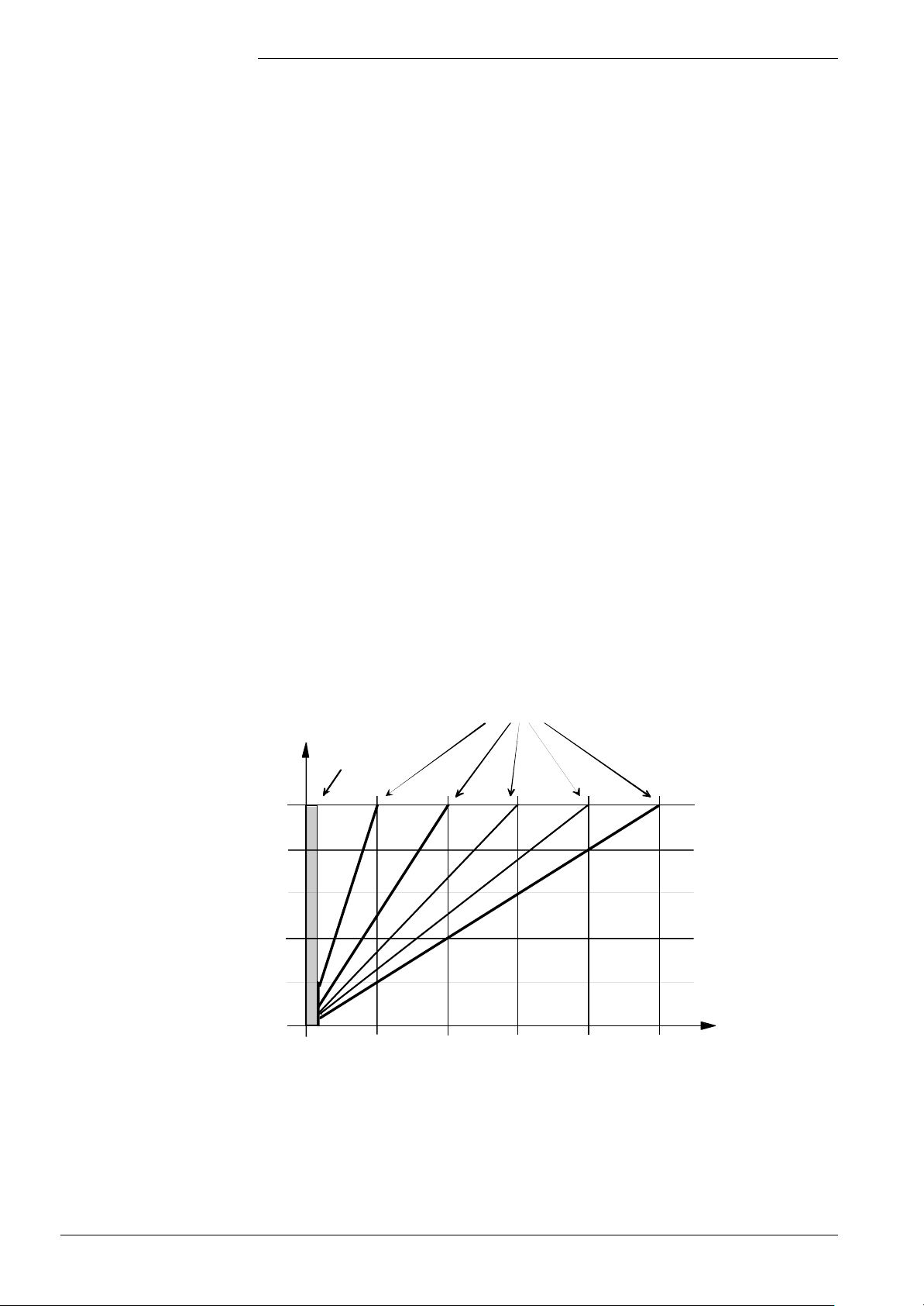
Inputs
The function of the input on the clip-in function module is defined via parameter
«KonfigEingangR».
Since the function of the input depends on the version of the clip-in function module, it is
checked first whether the parameterized function can be performed by the connected
module version.
If that is not the case, an error message will be delivered.
Digital input
Note
Analog input
Predefined setpoint
(temperature demand)
The input of the clip-in function module is used by the LMU… as another programmable
input ( → Programmable input of the LMU...).
The LP contact can never be read in via the input of the clip-in function module!
The following functions can be selected via parameter «KonfigEingangR»:
• 4 Predefined setpoint
• 5 Predefined output
• 6 Sensor input “Pressureless header”
In that case, the heat demand (temperature demand) is predefined via an analog signal.
This can take place via a current signal (4...20 mA) or voltage signal (DC 0...10 V).
The maximum value is defined via parameter «TanfoExtMax» on the LMU... The setting
range of this parameter is from 5 to 130 °C, the resolution being 1 °C.
The heat demand is derived from the the temperature demand.
For that, the threshold value is 5 °C. If the temperature demand is > (5+1) °C, the heat
demand will be set. If the temperature demand is < (5-1) °C, the heat demand will be
reset.
Both temperature and heat demand are assigned to heating circuit 1 of the LMU.. . .
Any additional heat demand that might exist at the same time will be accepted. The
temperature demand is determined via the maximum value.
U (V)
S = 5 °C!
10
8
6
4
2
0
5
0
Predefined setpoint
Parameter «TAnfoExtMax»
7494d42/0702
I (mA)
20
16
12
8
4
130 Temp. (°C)
90/171
Siemens Building Technologies Basic Documentation LMU54... / LMU64... CC1P7494en
HVAC Products 6 Clip-in function module AGU2.51x 07.11.2002
Page 91
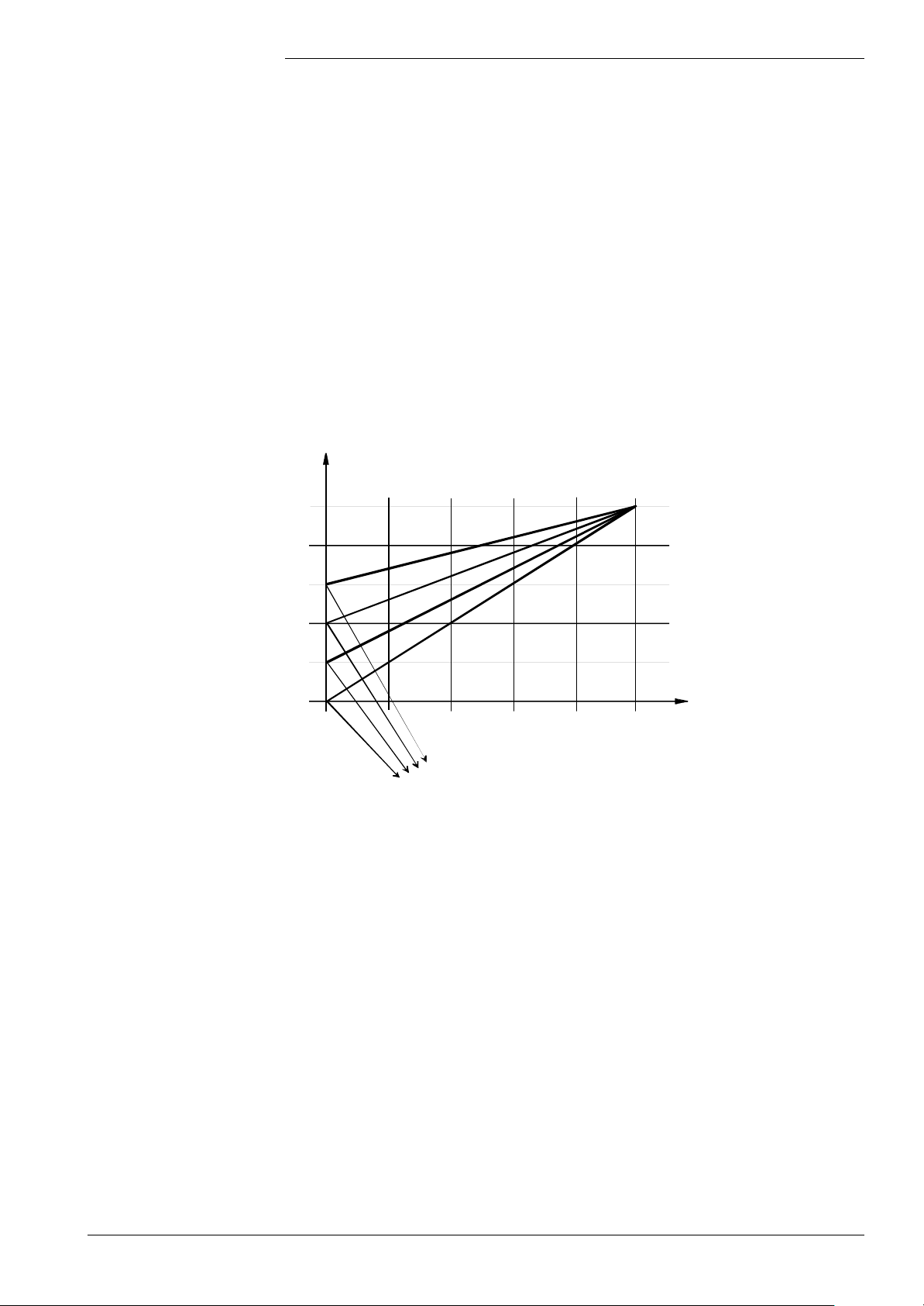
Parameter «PAnfoExtSchwelle» (%)
Predefined output
In this case, the relative boiler output is predefined via an analog signal.
This analog signal can be a current signal (0...20 mA, 4...20 mA) or a voltage signal (DC
0...10 V).
The analog signal is transmitted to the LMU… and applied to the possible output range
as a percentage value.
The threshold from which the analog signal shall activate the predefined load is defined
with the help of parameter «PanfoExtSchwelle». This parameter also defines the
minimum value of the analog signal.
The range of the analog signal between threshold and maximum value is converted into
an output signal in the range 0...100 %.
If the analog signal is near the parameterized threshold, the boiler will be operated at
the minimum relative output. In the case of maximum value of the analog signal, control
takes place with the maximum relative boiler output.
If the analog signal lies below the parameterized threshold, the predefined output will not
be active .
U (V)
I (mA)
Sensor input
“Pressureless header”
10
8
6
4
2
0
0
Predefined output
7494d43E/0702
100 (% rel. Boiler output)
20
16
12
8
4
0
This function facilitates control of the boiler to the flow temperature after the
pressureless header. For that purpose, a sensor located in the flow after the
pressureless header must be connected to the input of the clip-in function module.
The function is based on the following conditions:
− In addition to heating circuit 1, the hydraulic diagram contains no other heating circuits
− An operational boiler return sensor
Siemens Building Technologies Basic Documentation LMU54... / LMU64... CC1P7494en
HVAC Products 6 Clip-in function module AGU2.51x 07.11.2002
In pure heating mode (that is, when DHW heating is not active), the boiler temperature
is controlled to the value of this sensor. This means that the boiler is heated up until the
flow temperature after the pressureless header has reached the required level.
If no boiler return sensor is connected, an error code will be delivered.
If the state of the boiler return sensor changes from “Present” to “Faulty”, the actual
boiler temperature will be maintained again and an error code delivered. ...
91/171
Page 92

Control to the flow sensor after the pressureless header can work only if there is flow on
the consumer side. If the flow rate approaches zero, that sensor may no longer be used
for control.
For the detection of flow, the boiler return sensor is used.
As long as the consumer draws heat, the boiler return flow rate is always lower than the
flow after the pressureless header.
The boiler return temperature exceeds the level acquired by the sensor at the
pressureless header only when, on the consumer side, the flow rate approaches zero.
In that case, the sensor after the pressureless header is no longer used for control, but
the boiler return sensor. This state is maintained until the boiler return temperature
returns below the temperature level after the pressureless header.
In other words, the boiler is always controlled to the higher of the 2 temperatures.
92/171
Siemens Building Technologies Basic Documentation LMU54... / LMU64... CC1P7494en
HVAC Products 6 Clip-in function module AGU2.51x 07.11.2002
Page 93
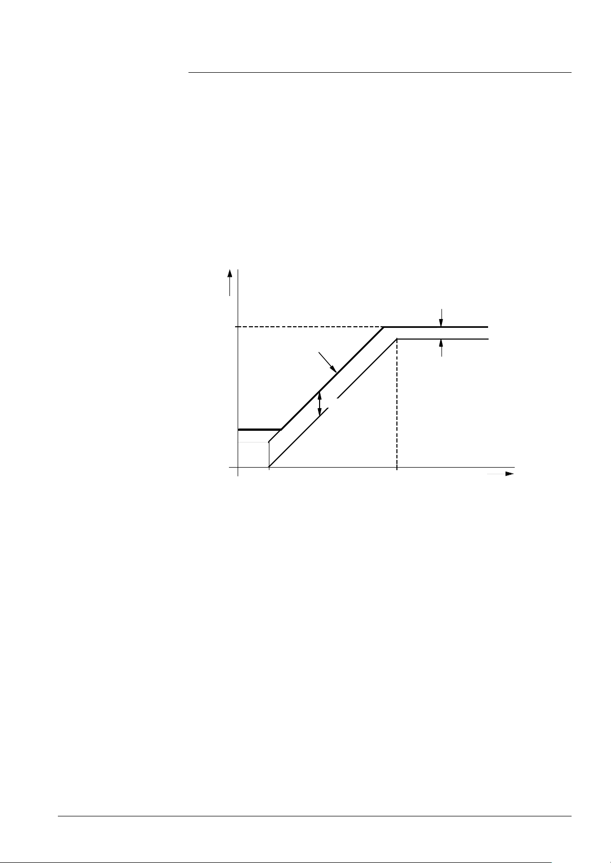
7 DHW control (BWR)
Boiler temperature
setpoint during DHW
heating with storage tank
systems
With storage tank systems, a boost is added to the DHW setpoint. This boost can be
parameterized and has an impact on the charging time of the storage tank.
During DHW heating, the boiler temperature setpoint is thus as follows:
Boiler temperature setpoint = DHW temperature setpoint + «TuebBw»
Boiler temperature setpoint: Boiler temperature setpoint during storage tank charging
DHW temperature setpoint: Current DHW temperature setpoint
TuebBw: Setting parameter for boiler temperature boost
As a result of the boost, the boiler temperature setpoint can reach inadmissibly high
levels. When limiting the boiler temperature setpoint, it may drop below «Bw-Soll»,
however.
For this reason, the boost can be limited to a minimum. In that case, the DHW setpoint
will be limited:
Boiler
setpoint
TkSmax
DHW setpoint + TuebBw
Min. boost
TuebBw
TkSmin
TbwSmin Max. DHW setpoint
Boiler temperature setpoint during storage tank charging
7494d16e/0102
DHW
setpoint
TbwSmin: Minimum DHW temperature setpoint
TkSmin: Minimum boiler temperature setpoint
TkSmax: Maximum boiler temperature setpoint
Max. Bw-Sollwert: Maximum DHW temperature setpoint
(TkSmax – minimum boost)
Minimum boost: 5 K
Hence, when reaching the boiler temperature limitations, the following effects will be
produced:
Boiler temperature setpoint < TkSmin
Limitation to «TkSmin». The storage tank’s charging time becomes shorter.
Boiler temperature setpoint > TkSmax
Limitation to «TkSmax» and reduction of boost. Limitation of the DHW temperature
setpoint. This means that the storage tank’s charging time becomes longer.
It is possible that only a lower DHW temperature setpoint will be reached.
93/171
Siemens Building Technologies Basic Documentation LMU54... / LMU64... CC1P7494en
HVAC Products 7 DHW control (BWR) 07.11.2002
Page 94
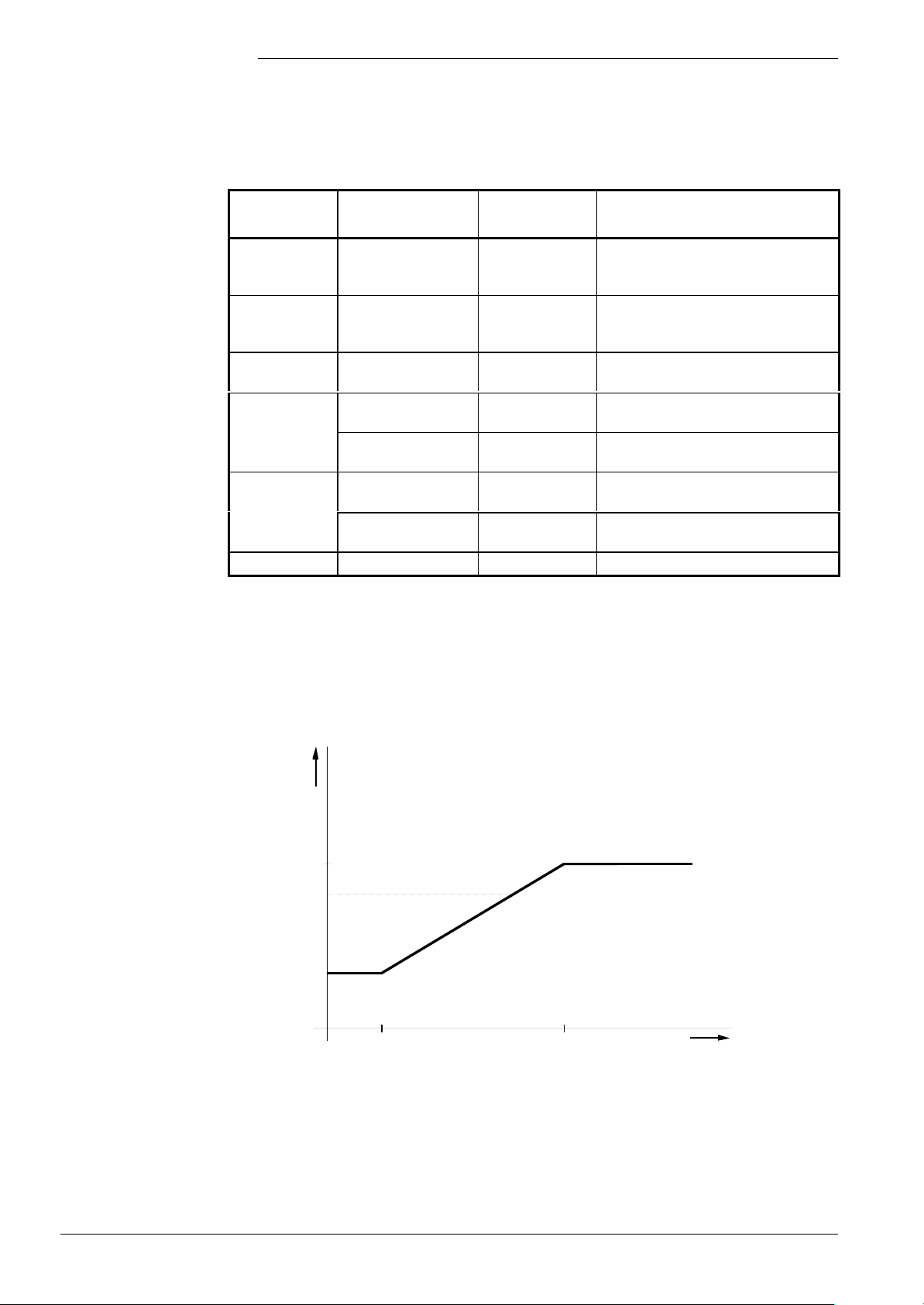
DHW temperature control
temperature setpoint with
Compensation variants
The compensation mode of DHW heating depends on the plant components connected
to the LMU… . By evaluating the components, «Compensation variant Bw» will be
generated (refer to chapter «Compensation variant Bw»).
The setpoint used depends on the compensation variant:
Compensation
DHW release DHW setpoint Description
variant DHW
DHW heating is locked, the DHW setpoint
Locked 0 (always locked) TbwSmin
Emergency
operation
Fixed value
control
AGU2.310...dependent
RU-dependent
RVA-dependent released TbwSollRva DHW setpoint of RVA will be adopted
1 (always released)
1 (always released) TbwSollMmi DHW setpoint of HMI will be adopted
DHW off Bw_Soll_Frost
DHW on
Follows from RU
locked
Follows from RU
released
(TbwSmin+
TbwSmax)/2
TbwSollMmiRed
TBwSollMmi
TbwSmin
TdhwSet DHW setpoint of RU will be adopted
is initialized with the minimum setpoint,
no frost protection possible
Since there is no facility to set the DHW
temperature setpoint, the mean value of
the setpoint setting range is used
DHW heating is locked
Frost protection for DHW is active
According to the switching program of the
AGU2.310...
Adoption of frost protection setpoint from
the LMU...
The resulting DHW temperature setpoint will be limited to the permissible setting range.
The important criterion here is the type of system used - storage tank or instantaneous
heating system.
Limitation of the DHW
storage tank systems
The setpoint setting range with storage tank systems follows from the parameterization
of the boiler and the DHW heating circuit:
DHW
setpoint
limited
TbwSmax
50 °C
TbwSmin
TbwSmin TbwSmax
Boiler temperature setpoint during storage tank charging
7494d17E/0201
TbwSoll
TbwSmin: Minimum DHW temperature setpoint
TbwSmax: Maximum DHW temperature setpoint
94/171
Siemens Building Technologies Basic Documentation LMU54... / LMU64... CC1P7494en
HVAC Products 7 DHW control (BWR) 07.11.2002
Page 95

The maximum DHW temperature setpoint «Max.Bw-Sollwert» follows from the limitation
to the maximum permissible boiler temperature setpoint.
Maximum DHW temperature setpoint = Min [TbwSmax, (TkSmax – 5K)]
This ensures that the resulting DHW temperature setpoint can be handled.
In the special case «Stratification storage tank», the minimum DHW temperature
setpoint is 50 °C.
If «TkSmax» was parameterized to < 50 °C, DHW charging will be locked and a status
code delivered.
Position of diverting
valve
Pump / diverting valve
overrun
Storage tank systems
Storage tank control via
sensors
When there is no more demand for heat, the diverting valve will maintain the operating
position it had assumed last.
• Relevant outputs are activated in the DHW circuit
- If «B2 > TqNach»: As long as «B2 < TqNach»
or
- If «B2 < TqNach»: For the fixed time of one minute
In the case of DHW heating with a storage tank system, only the sensor for «TbwIst1» is
required.
The sensor for «TbwIst2» can be used as an option.
If connected, the sensor for «TbwIst2» with the storage tank can only generate but not
stop a demand for DHW.
The switch-on conditions for DHW demand are the following:
• If the sensor for «TbwIst1» is connected:
TbwIst1 < DHW setpoint – SdBwEin1
• If the sensor for «TbwIst1» and the sensor for «TbwIst2» are connected, following
also applies:
TbwIst2 < DHW setpoint – SdBwEin2
and
DHW setpoint – SdBwEin1 < TbwIst1 < DHW setpoint + (SdBwAus1Max – SdBwMin)
The minimum switching differential «SdBwMin» (value: 2 K) ensures that there is a
minimum interval between the switch-on and the switch-off point of the sensor for
«TbwIst1».
The demand for DHW will be generated when the switch-on condition is satisfied:
The demand for DHW causes activation of the relevant pump. In the case of a
modulating speed pump, DHW charging takes place with the maximum volumetric flow
(minimum degree of modulation):
Degree of modulation of pump = QmodMin
The demand for DHW is stopped when at the sensor for TbwIst1:
• TbwIst1 > DHW setpoint + SdBwAus1Max
When the demand for DHW is stopped, pump overrun starts. In the case of a
modulating speed pump, pump overrun is executed with the maximum volumetric flow
(minimum degree of modulation):
Degree of modulation of pump = QmodMin
The burner is switched on when «TkIst < (TkSoll – SdHzEin1)». (TkSoll = DHW
setpoint + TuebBw).
The output demand on the burner is controlled between «LmodTL» and «LmodVL»
or, in the case of an active speed limitation, between «N_TL» and «N_VL».
95/171
Siemens Building Technologies Basic Documentation LMU54... / LMU64... CC1P7494en
HVAC Products 7 DHW control (BWR) 07.11.2002
Page 96
Storage tank control
via thermostat
Storage tank systems can also be operated with an external thermostat.
Storage tank control by a thermostat is released when a storage tank system has been
parameterized (systems 2, 3, 8, 34, 35, 40, 44, 50, 51, 56, 60, 66, 67, 72, 76, and 81).
The thermostat is to be connected to the DHW flow switch or, in place of the DHW
sensor 1 to the LMU… The input to be used must be selected via parameterization:
KonfigRg42 = 0: DHW thermostat to be connected to the input of the DHW flow switch
KonfigRg42 = 1: DHW thermostat to be connected to input «DHW sensor 1»
Connecting to the DHW sensor input
When connecting the thermostat to the DHW sensor input, high-quality contact material
is mandatory (e.g. gold-plated contacts) since the signal voltage at that input is DC 5 V.
The second DHW sensor must not be present.
If a short-circuit is detected at the input, no status code will be delivered. The signal is
interpreted directly as a DHW demand signal.
Read-in value ≤ open-circuit threshold Stopping the demand for DHW
Read-in value ≥ short-circuit threshold Triggering the demand for DHW
Connecting to the DHW flow switch input:
When using this connection, no DHW sensor may be connected to the LMU... (neither
«Bw1» nor «Bw2» sensor). Otherwise, the demand for DHW will be suppressed.
Stratification storage tank
The demand for DHW follows from the state of the «Bw-Flow-Switch» input:
0: Stopping the demand for DHW
1: Triggering the demand for DHW
With both types of connection, the maximum DHW setpoint is used for calculating the
boiler temperature setpoint (during storage tank charging) when there is an active
demand for DHW:
DHW setpoint = TbwSmax
In that case, the DHW settings made on the HMI, RU or RVA… are of no importance.
The setting value on the QAA73... will be locked.
Control of the pump is the same as with «Storage tank control by sensor».
Stratification storage tank systems require a modulating pump in the DHW charging
circuit. That pump is controlled in accordance with the criteria described below.
The following table shows when modulating control of heating circuit 1 without the clip-in
module is possible with the LMU... basic unit.
Plant diagram Heating circuit 1
9, 41, 43, 57, 59, 73, 75 Multispeed
10, 42, 58, 74, 83 Multispeed or modulating
96/171
Siemens Building Technologies Basic Documentation LMU54... / LMU64... CC1P7494en
HVAC Products 7 DHW control (BWR) 07.11.2002
Page 97
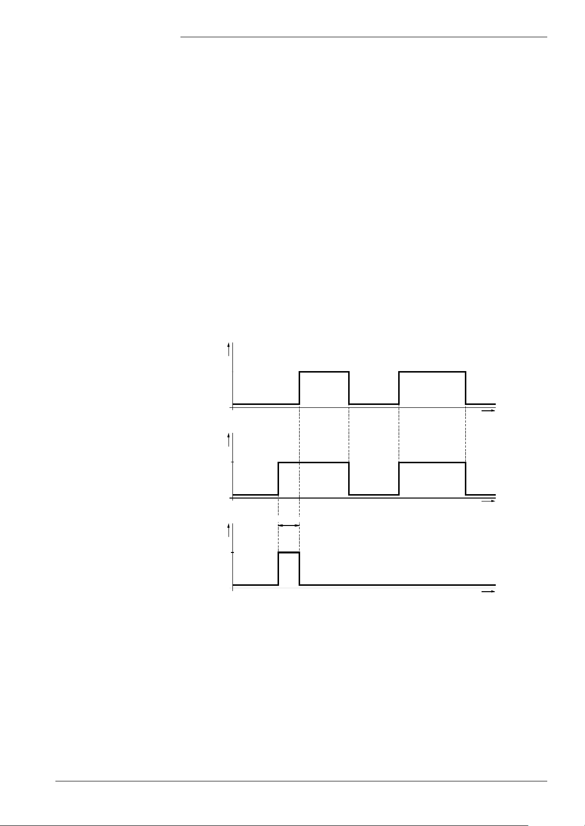
In the case of the stratification storage tank, a differentiation is made between 2 types of
DHW charging modes:
1. Full charging.
2. Recharging.
The criteria for these 2 operating modes are dependent on the compensation variant of
DHW.
• With compensation variant Bw = «RU-dependent»
Full charging is released only when the switching program is in the first DHW forward
shift period of the respective day.
This is transmitted from the QAA73... via bus interface.
Note: Other types of OpenTherm RU do not support this function; this means that
when using an RU of other manufacture, only recharging will be activated.
Release of full charging:
0: Full charging of stratification storage tank locked
1: Full charging of stratification storage tank released
Depending on the DHW mode on the RU (heating program with forward shift of DHW or
own DHW program), full charging is released in 1 of 2 different ways.
1. Full charging during the DHW forward shift against the heating program:
Heating program
Nom.
Red. / frost.
DHW program
Nom.
Red. / frost.
Forward shift
Charging mode
Full charging
Recharging
7494f04E/0102
Charging of stratification storage tank with DHW forward shift
t
t
t
During the DHW forward shift time, the QAA73... sends:
FreigabeDurchladung = 1
This gives rise to the release of the stratification storage tank’s full charging. If there are
further changes from «Reduced» to «Nominal level» on the same day, there will be no
more forward shifts. After the first forward shift:
FreigabeDurchladung = 0
This gives rise to the release of the stratification storage tank’s recharging.
97/171
Siemens Building Technologies Basic Documentation LMU54... / LMU64... CC1P7494en
HVAC Products 7 DHW control (BWR) 07.11.2002
Page 98
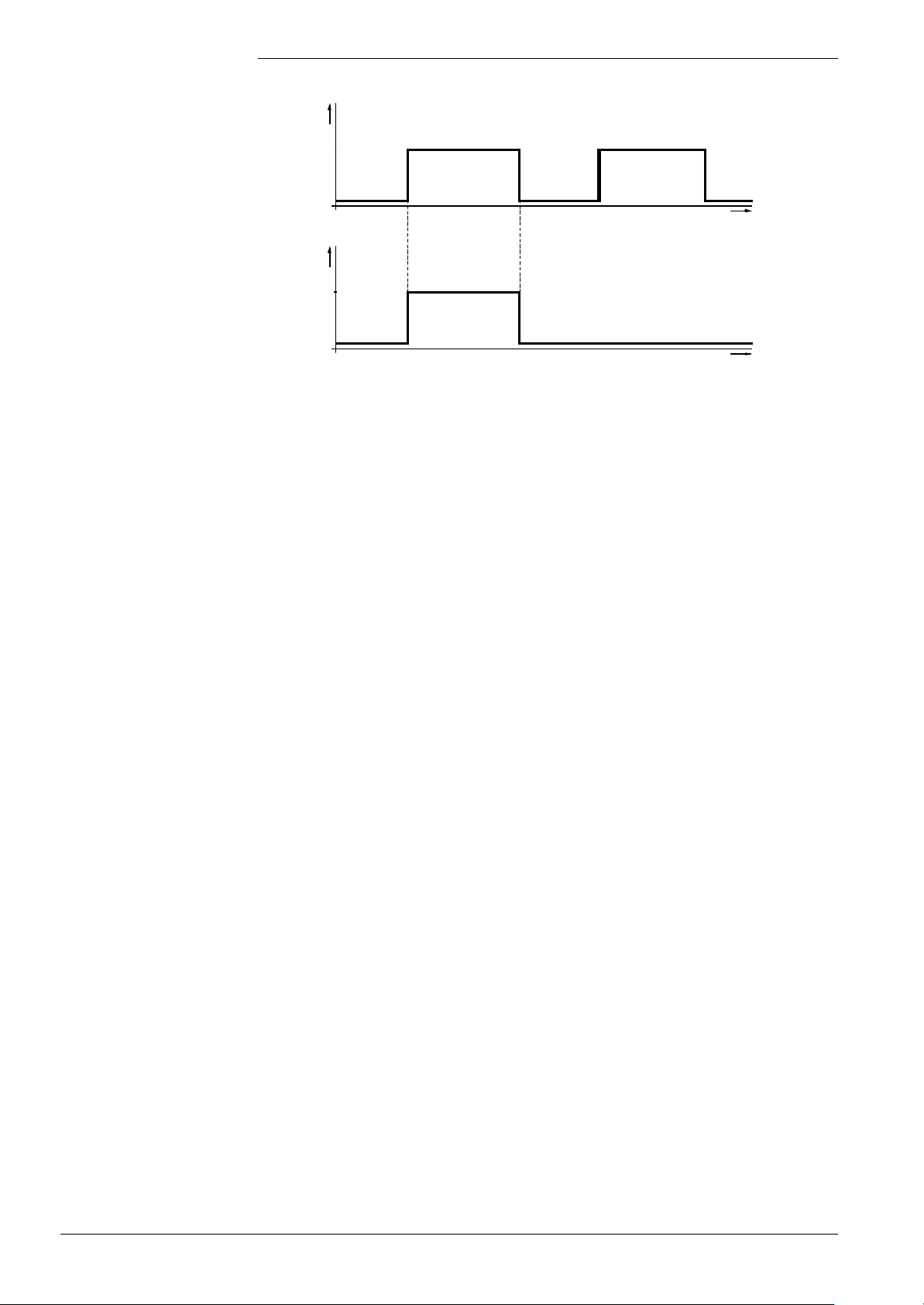
2. Full charging during the first DHW phase of the day:
DHW program
Nom.
Red. / frost.
Charging mode
Full charging
Recharging
7494f05E/0102
Charging of stratification storage tank with own DHW program
t
t
Full charging will be released during the first nominal phase of the DHW program:
Release of full charging = 1
If additional charging is required on the same day, only recharging takes place.
Release of full charging = 0
If no DHW program is selected on the QAA73... (continuously frost protection, reduced
or nominal level), following applies:
Release of full charging = 0
This means that recharging is continuously used.
• With compensation variant Bw = «RVA-dependent, fixed value control or
emergency operation»
Full charging is possible only if, for heating circuit 1, an external time switch is
connected to the LMU...
This will be predefined via parameterization.
KonfigRg1.Schaltuhr1:
0: No time switch present, it is always recharging that is released
1: A time switch for heating circuit 1 is connected to the room thermostat
If a time switch is used, full charging during the setback phases is released.
State of room thermostat input:
0: Full charging released
1: Recharging released
• With compensation variant Bw = «Locked»
Charging of the stratification storage tank is locked.
With the stratification storage tank, both sensors (for «TbwIst1» and «TbwIst2») must be
connected. If the sensor for «TbwIst1» has a short-circuit or open-circuit, the demands
for recharging and full charging of the stratification storage tank will be locked and the
relevant status code delivered.
If the sensor for «TbwIst2» has a short-circuit or open-circuit, full charging of the
stratification storage tank will no longer be possible. To have DHW available also if the
sensor for «TbwIst2» is faulty, only recharging with the help of the sensor for «TbwIst1»
is provided.
The boiler temperature setpoint is determined by boiler temperature setpoint =
BwSollwert + boost, whereby the minimum limitation is
boiler temperature setpoint = 50 °C + TuebBw.
98/171
Siemens Building Technologies Basic Documentation LMU54... / LMU64... CC1P7494en
HVAC Products 7 DHW control (BWR) 07.11.2002
Page 99

Full charging of the
stratification storage tank
With full charging, the temperature of the entire storage tank is raised to the setpoint
temperature while the pump is running at low speed. When the temperature at the upper
sensor for «TbwIst1» is too high (> TbwSmax), the demand for heat will be stopped.
Demand for DHW is stopped when, at the sensors for «TbwIst2» and «TbwIst1»:
TbwIst2 < DHW setpoint – SdBwEin2
and
TbwIst1 < TbwSmax – SdBwEin1
Demand for DHW is stopped when, at the sensor for «TbwIst2» or «TbwIst1»:
TbwIst2 > DHW setpoint + SdBwAus2Max
or
TbwIst1 > TbwSmax + SdBwAus1Max
During full charging, the charging pump runs at low speed.
This speed can be adjusted independently of heating operation, which means that it has
its own parameter «NqmodMinBw».
The burner is put into operation when TkIst < (TkSoll – SdHzEin1) (TkSoll =
TbwSoll + TuebBw).
The output demand on the burner will be adjusted between «LmodTL» and «LmodVL»
or, with active speed limitation, between «N_TL» and «N_VL».
Recharging of the
stratification storage tank
If, during active full charging, the release criterion for full charging becomes obsolete,
the demand for DHW will be stopped based on the criteria of recharging.
With recharging, it is only the upper part of the storage tank that is brought to the
setpoint temperature while the pump runs at full speed.
Function «Recharging of the stratification storage tank» will be activated when the
conditions for full charging are not satisfied or when, in full charging mode, the sensor
for «TbwIst2» is faulty.
The evaluation for DHW demand is made only based on the sensor for «TbwIst1».
Demand for DHW is stopped when, at the sensor for «TbwIst1»:
TbwIst1 < BwSoll – SdBwEin1
Demand for DHW is stopped when, at the sensor for «TbwIst1»:
TbwIst1 > BwSoll + SdBwAus1Max
In the case of DHW demand or pump overrun, the modulating pump runs at maximum
speed or with the minimum degree of modulation.
QmodMin: Minimum degree of modulation, that is, maximum pump speed
The burner is put into operation when «TkIst < (TkSoll – SdHzEin1)» (TkSoll =
TbwSoll + TuebBw).
The output demand on the burner will be adjusted between «LmodTL» and «LmodVL»
or, with active speed limitation, between «N_TL» and «N_VL».
If, during active recharging, the release criterion for recharging becomes obsolete, the
demand for DHW will be stopped based on the criteria of full charging.
99/171
Siemens Building Technologies Basic Documentation LMU54... / LMU64... CC1P7494en
HVAC Products 7 DHW control (BWR) 07.11.2002
Page 100

Instantaneous DHW system
Notes
− If, due to the flow switch, startup is aborted before the fuel valve opens (DHW flow
switch open again), no overrun will be triggered
− If DHW heating is switched off by the QAA73... or AGU2.310, no DHW heat demand
will be generated, even if a flow switch signal is active
− If, in standby or reduced DHW mode, the frost protection setpoint is entered as a
temperature demand, this temperature will no longer be additionally limited to
«TbwSmin»
− If the DHW temperature falls below 5 °C, the frost protection function for the
instantaneous DHW heater will be activated. When the DHW temperature exceeds
7 °C, the frost protection function will be deactivated.
During the time the frost protection function for the instantaneous DHW heater is
active, the heat exchanger for DHW is heated up at the minimum rate. When the flow
temperature exceeds parameter «TkFrostAus», the 2-position controller will be
switched off. When the flow temperature returns to a level which lies 2 °C below that
value, the 2-position controller will switch the burner on again.
The frost protection function has a higher priority than heat demand from the heating
circuits, but the priority of DHW outlet temperature control is even higher
− In systems with primary heat exchangers, there is neither frost protection for DHW nor
DHW comfort
Hydraulic diagram
Operating mode
Outlet temperature control
(FS-DHW is closed)
DHW demand
Control
End of demand
• Instantaneous DHW heating system with plate heat exchanger for sanitary water
(systems 5 / 6 and extended systems)
• DHW sensor B3 must be located at the DHW outlet. It is placed such that it can
acquire both
− the DHW outlet temperature in instantaneous DHW mode, and
− the temperature of the plate heat exchanger in comfort mode (if comfort mode with
sensor B3 was selected)
• By closing FS-DHW (external contact)
• Control sensor: Directly via B3, PID control
• Boiler output: Modulating between minimum and maximum boiler output
• Setpoint: T_set_DHW - according to the DHW compensation variant
(for ext. potentiometer HMI, QAA73..., etc.)
• Differentials: SdBwEin1, SdBwAus1Min, SdBwAus1Max
• By opening FS-DHW
Pump / diverting valve
• Q1 / diverting valve are always in operation ( → DHW circuit)
overrun
Comfort control
(after FS-DHW opening)
DHW demand
• After outlet temperature control, comfort control will be activated for a certain period of
time:
- Without additional heat demand: 1)Time «Z_BwComfort1»
- With additional heat demand:
100/171
Siemens Building Technologies Basic Documentation LMU54... / LMU64... CC1P7494en
HVAC Products 7 DHW control (BWR) 07.11.2002
1)
Time «Z_BwComfort2»
 Loading...